
Study of the Interaction of Cement-Based Materials for 3D Printing with Fly Ash and Superabsorbent Polymers


Abstract
1. Introduction
2. Materials
2.1. Binder
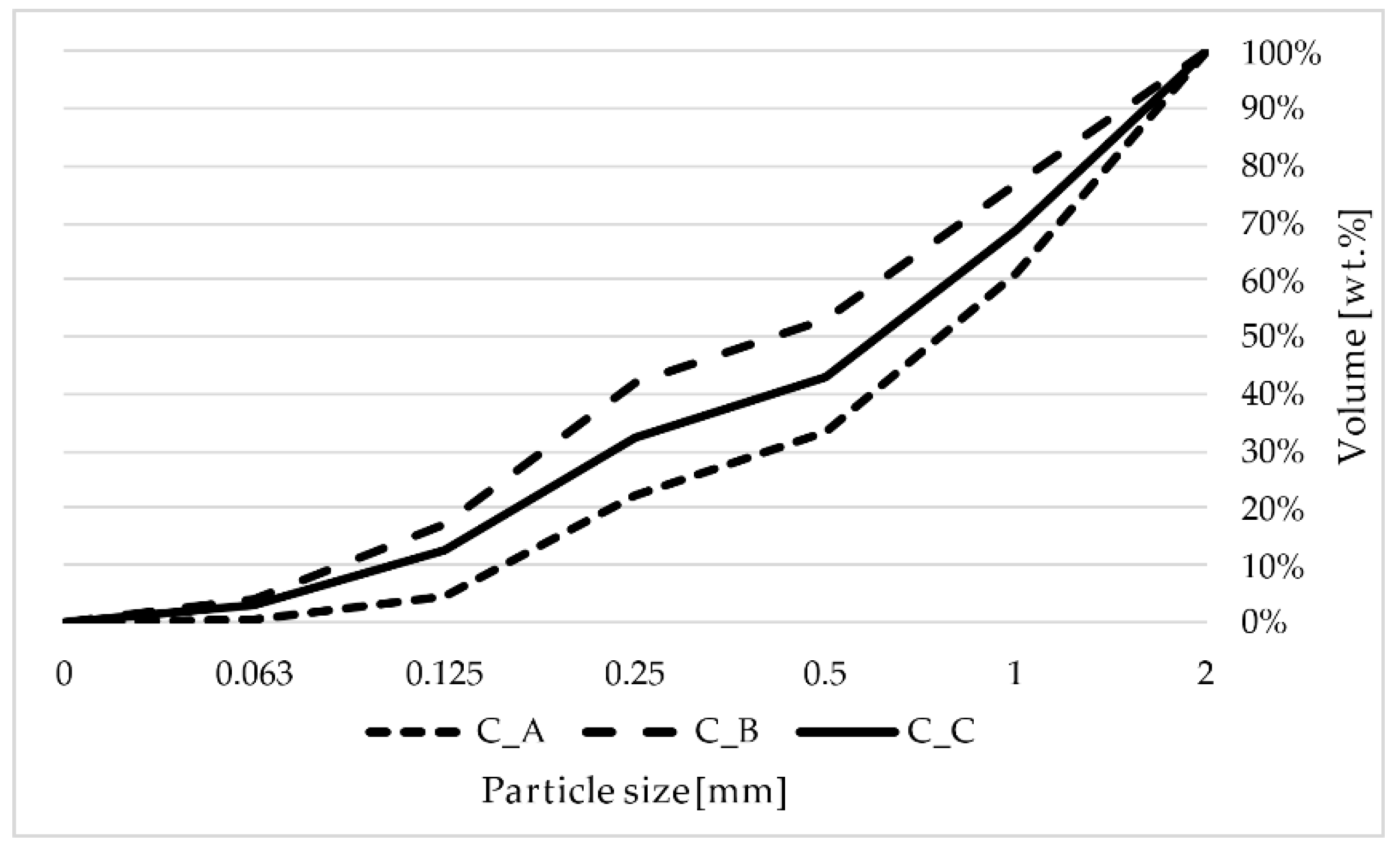
2.2. Aggregate
2.3. Admixtures
2.4. High Temperature Fly Ash
2.5. SAP–Creabloc SIS
3. Methods
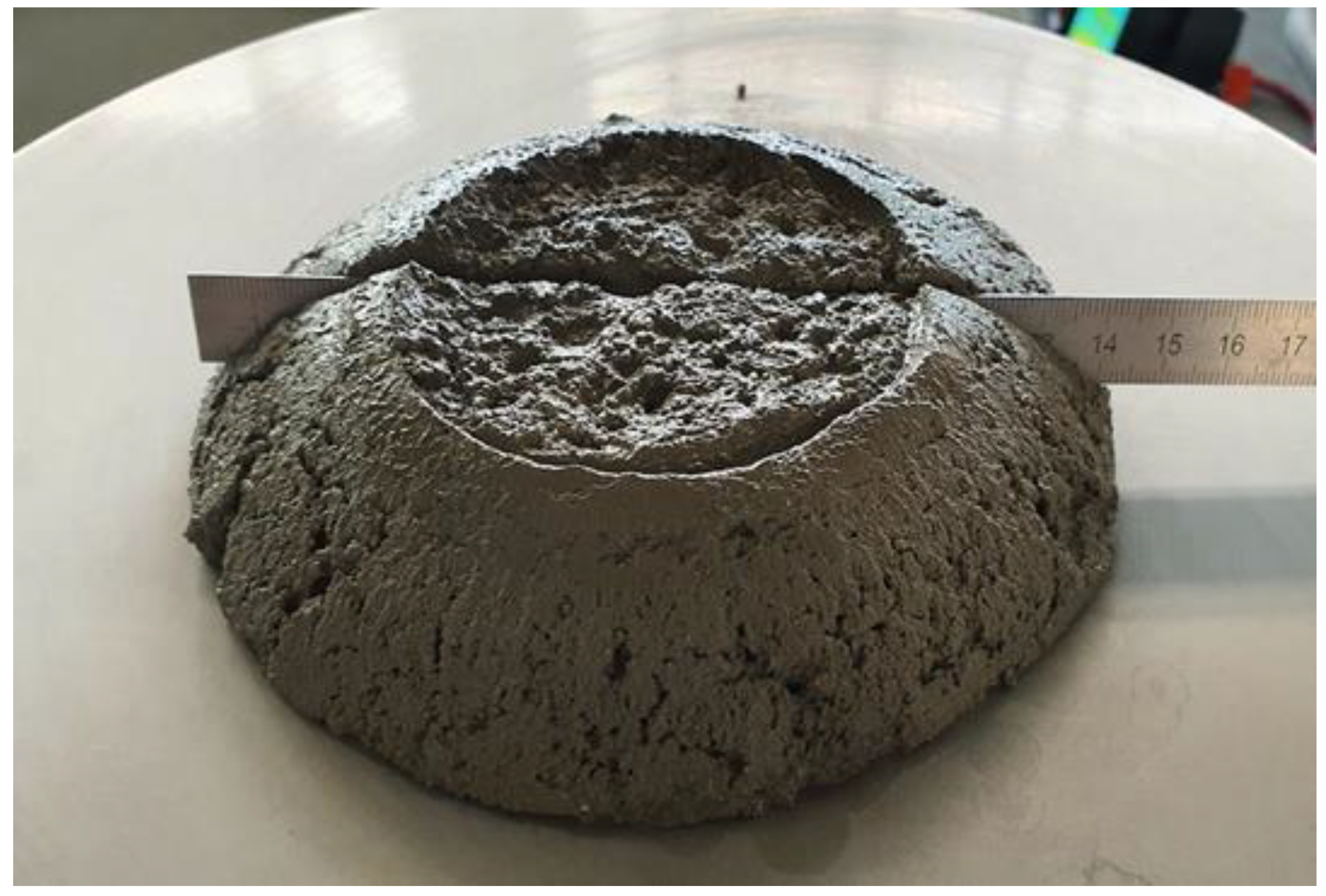
3.1. Consistency
3.2. Volumetric Weight
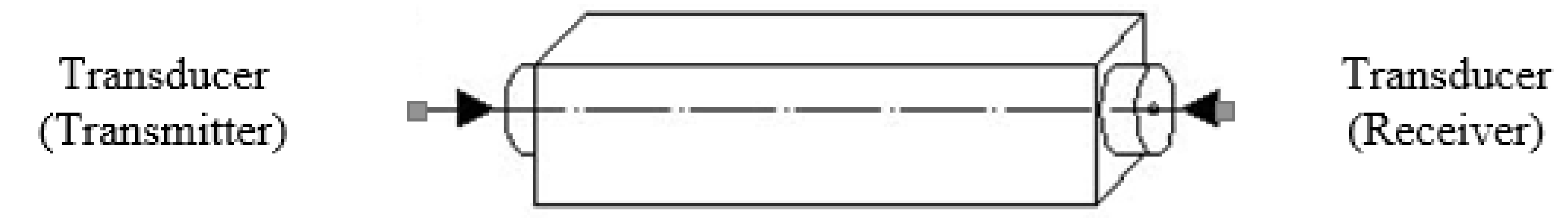
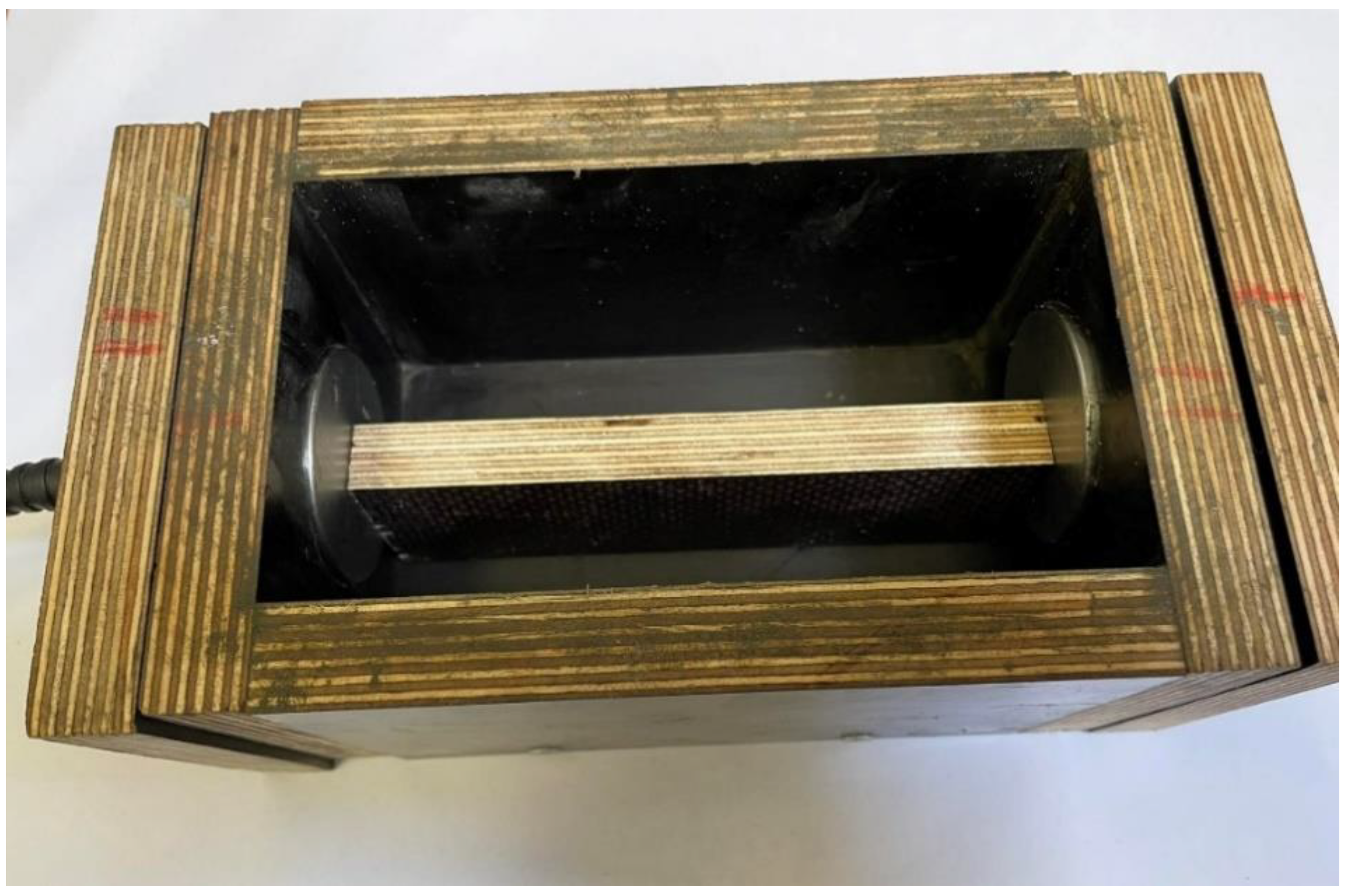
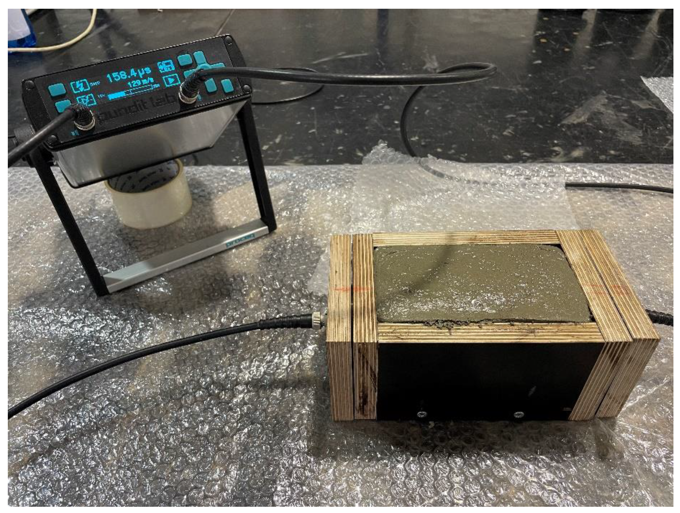
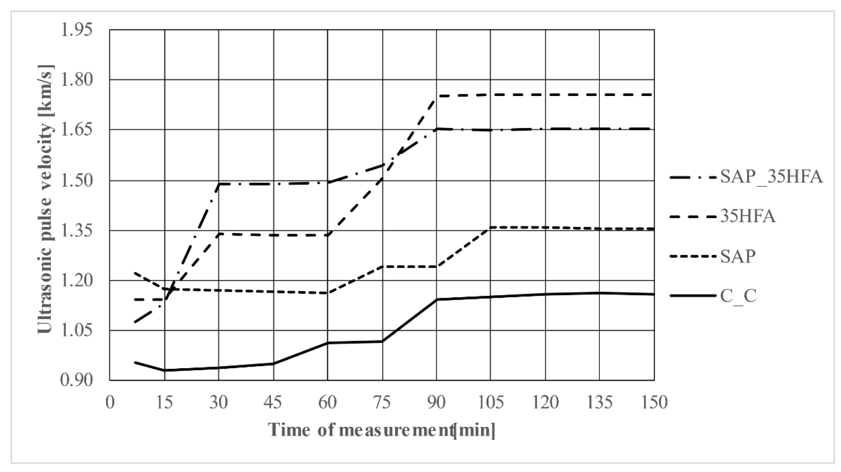
3.3. Ultrasonic Analysis
- The first measurement was realized 7 min after the contact of the cement with the water in the mixture
- The following measurements were realized after 15 min intervals (referred to the contact of cement with water in the mixture)
- The measurement was terminated when at least 3 values of the passage time of the ultrasonic pulse differed by a maximum of 1%.
- V—ultrasonic pulse velocity [km/s]; L—length of measuring base [mm]; T—transit time [μs].
- EU—dynamic Young’s modulus of elasticity [Gpa]; D—density of fresh mortar [kg/m3].
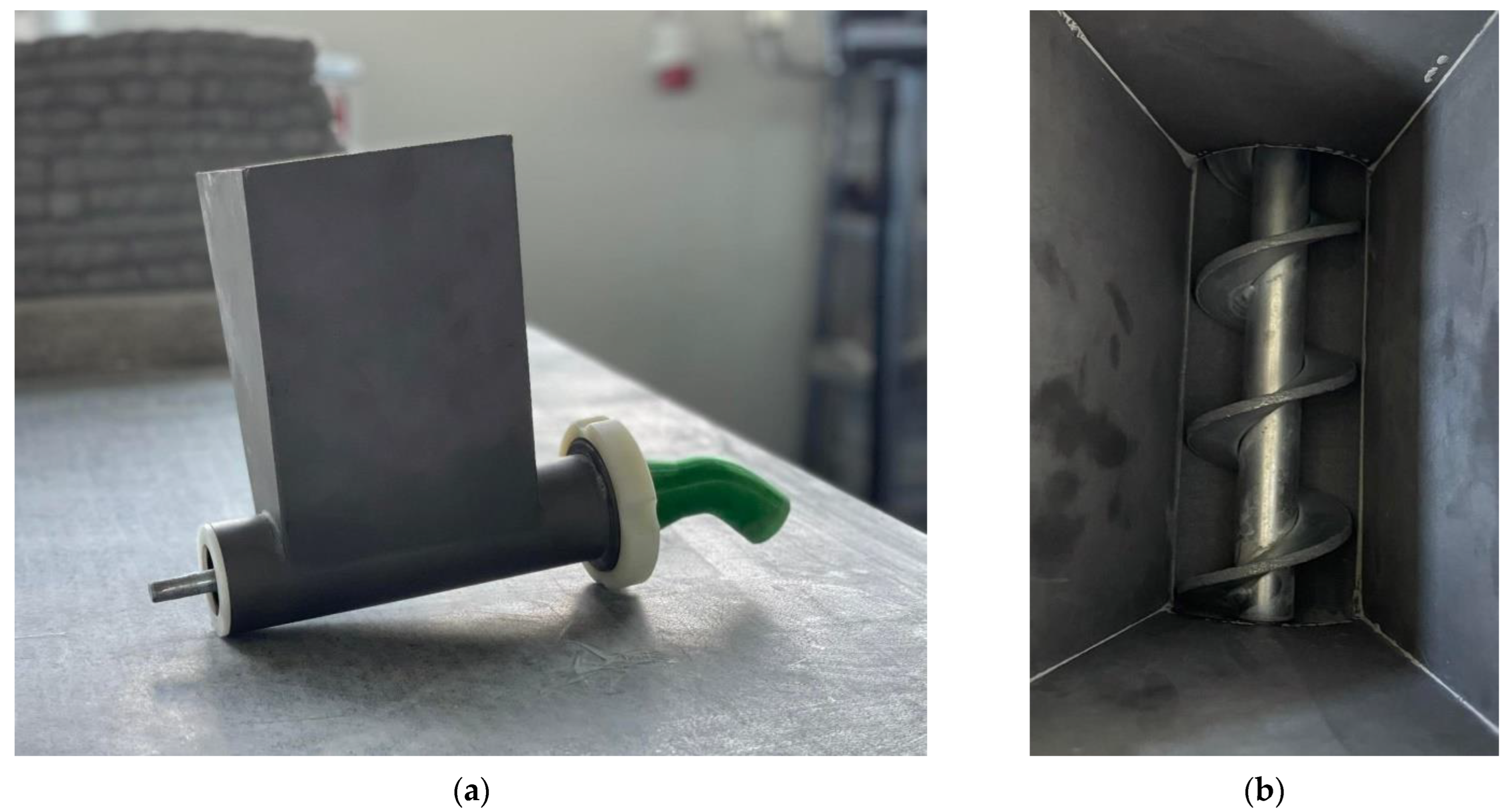
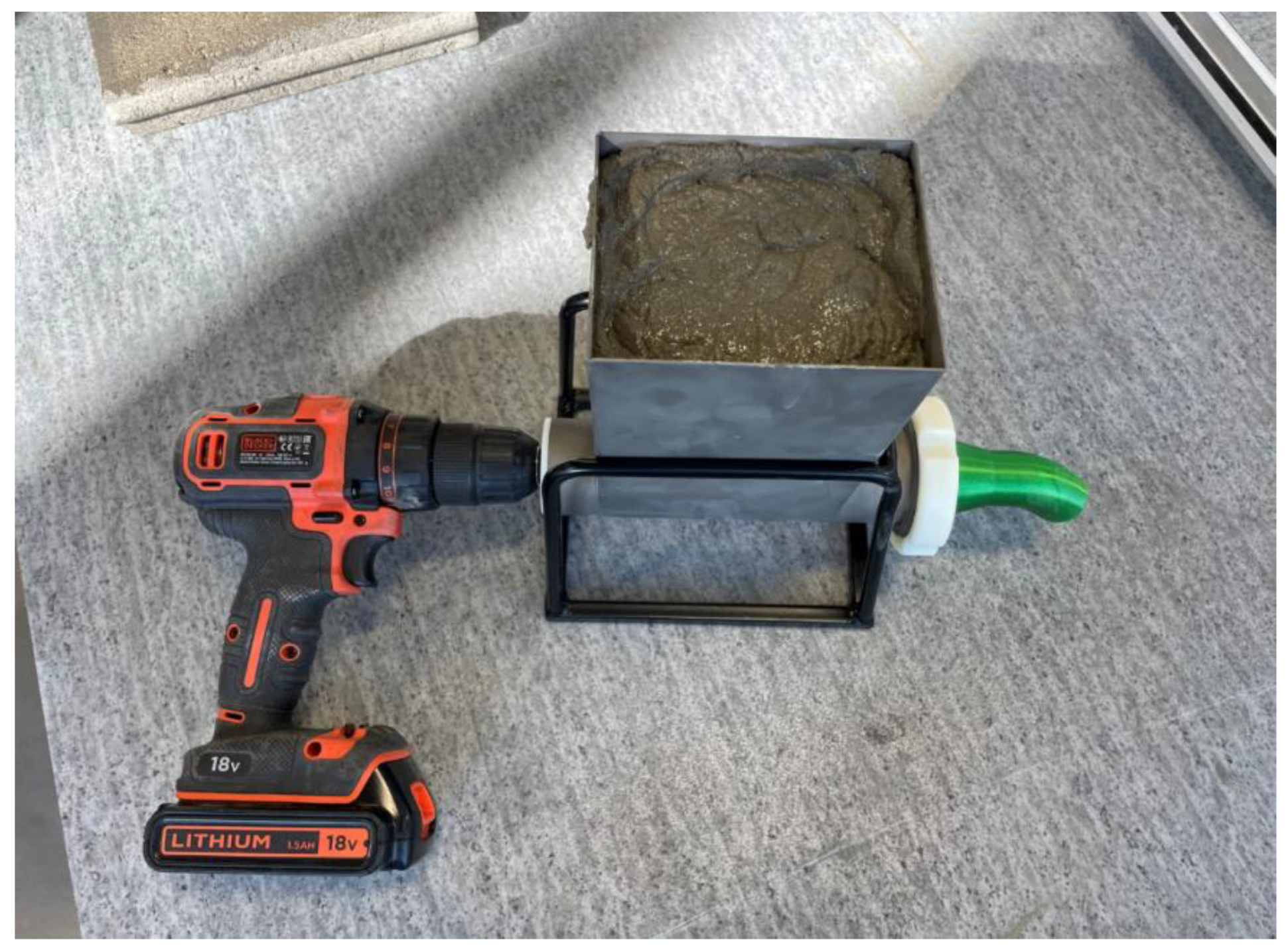
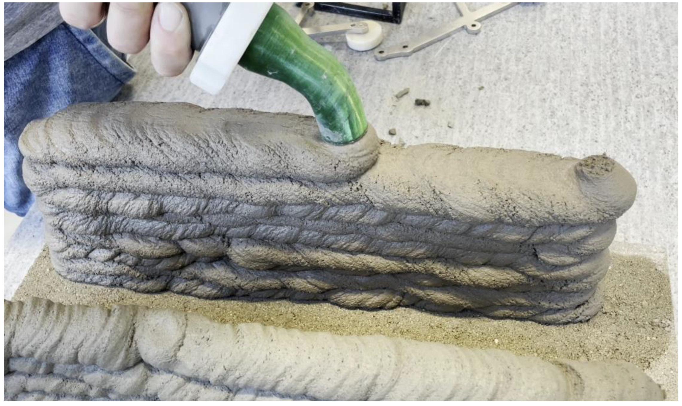
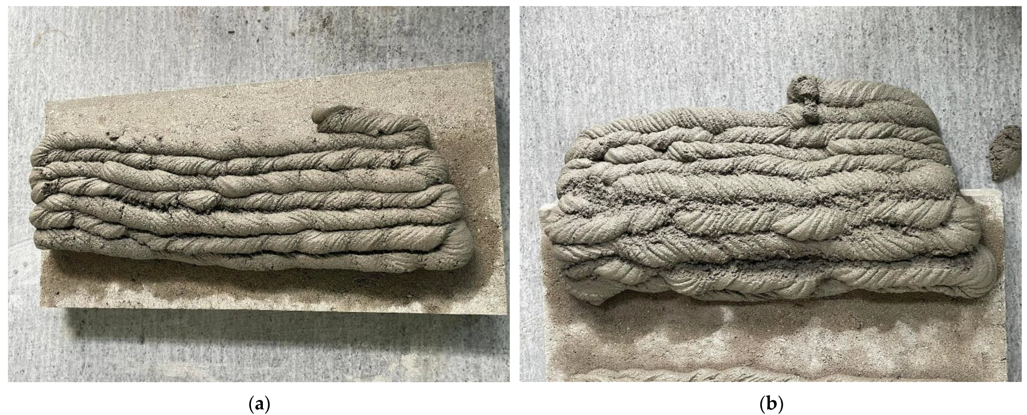
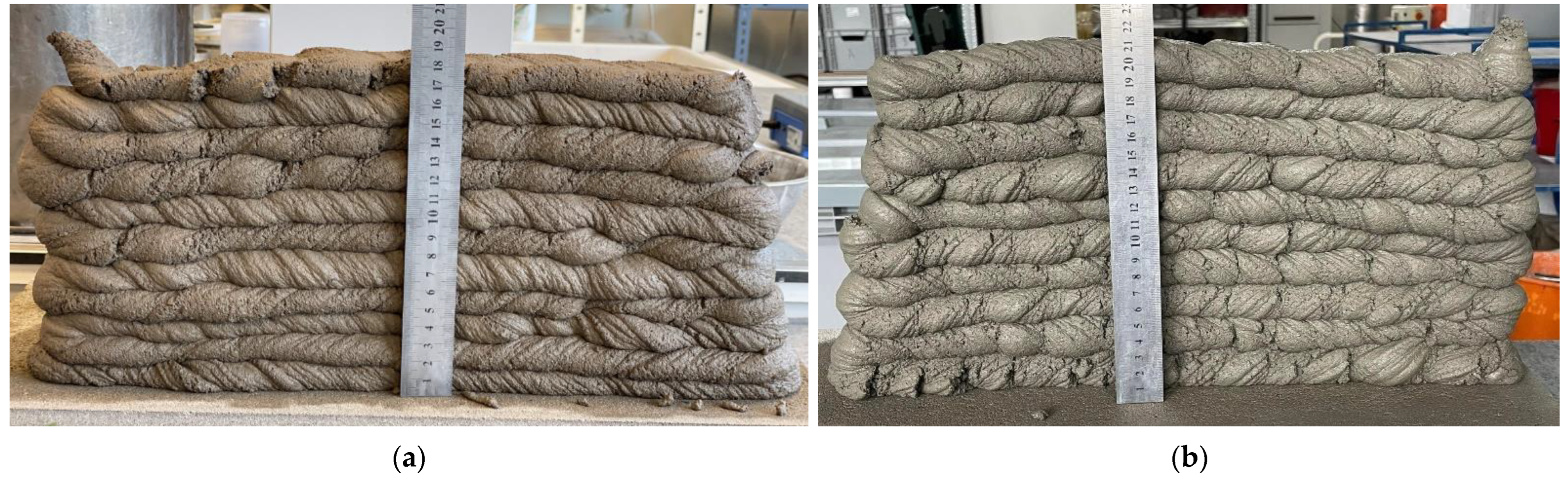
3.4. Buildability
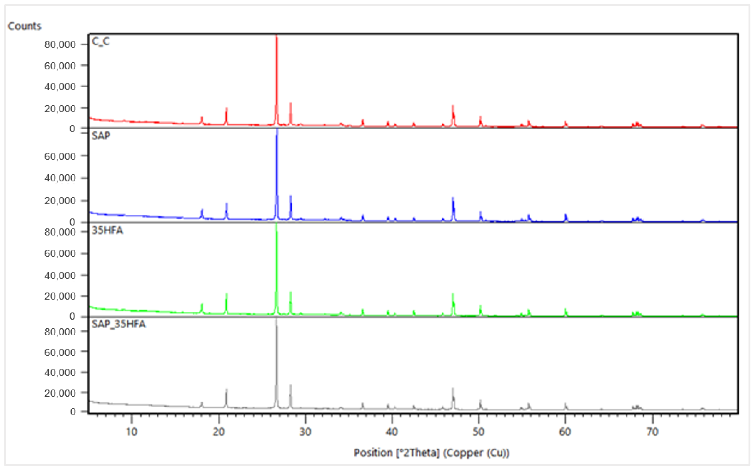
3.5. X-ray Diffraction Analysis
3.6. Compressive Strength
3.7. Flexural Strength
4. Mixture Proportions
5. Results and Discussion
5.1. Consistency
5.2. Volumetric Weight
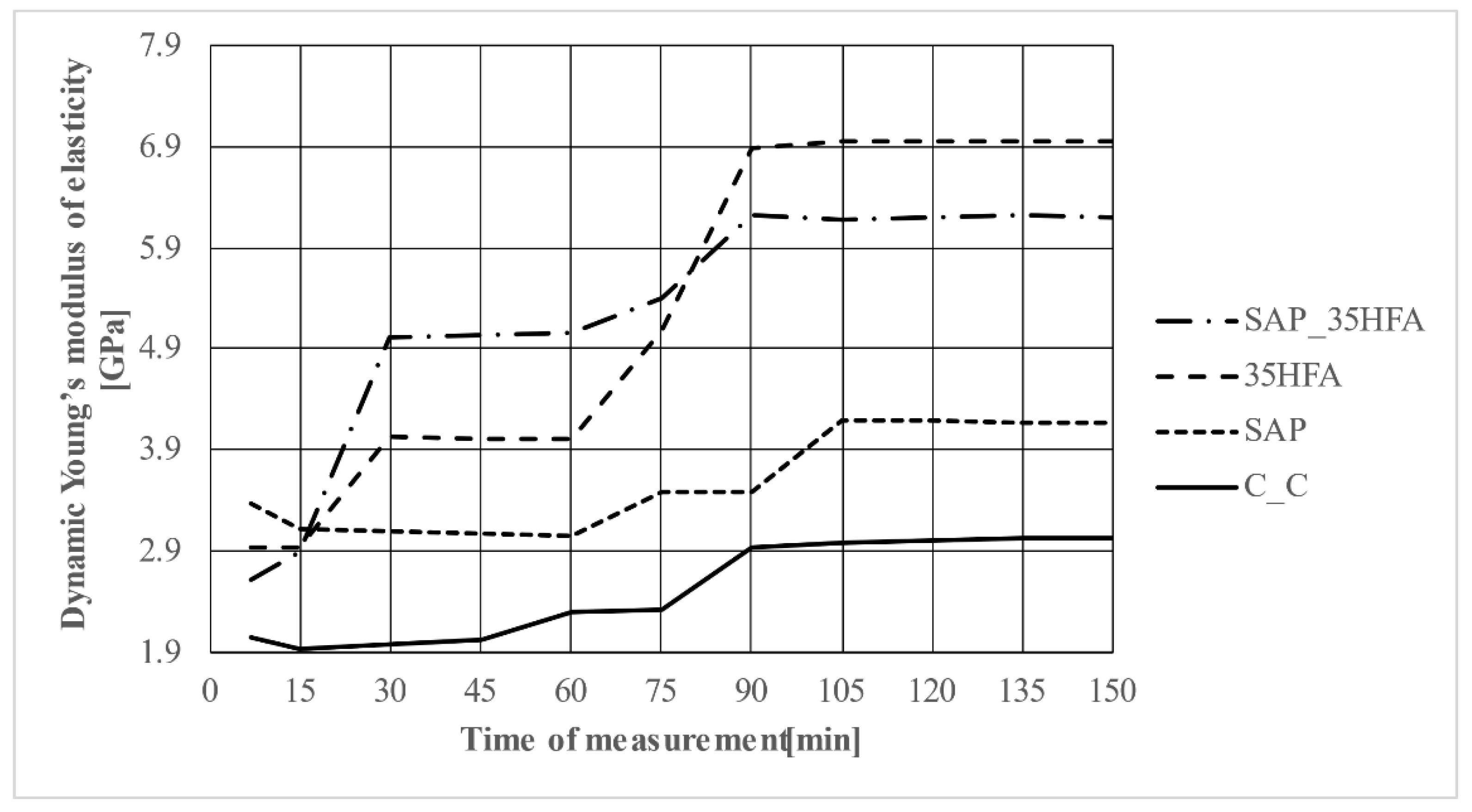
5.3. Ultrasonic Analysis
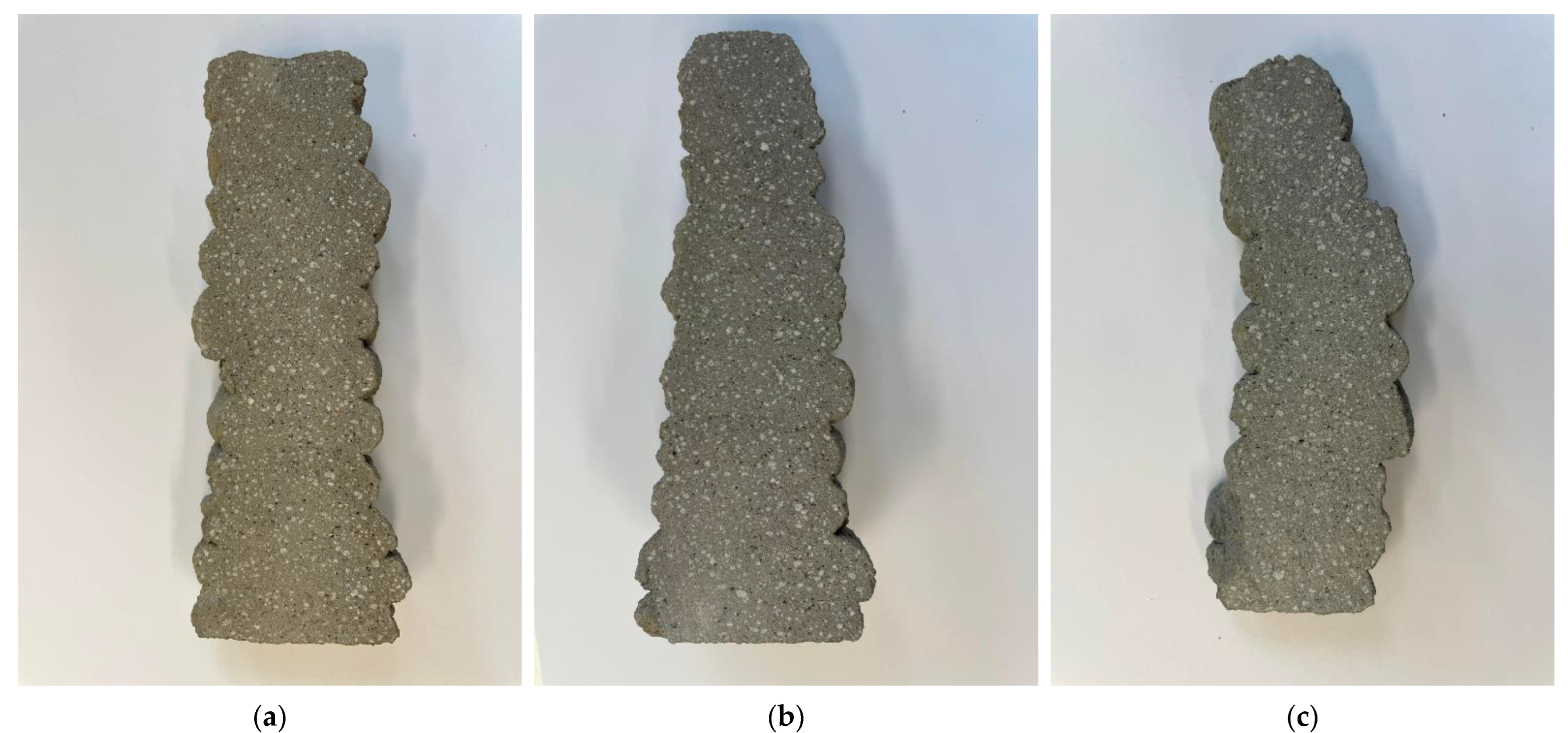
5.4. Buildability
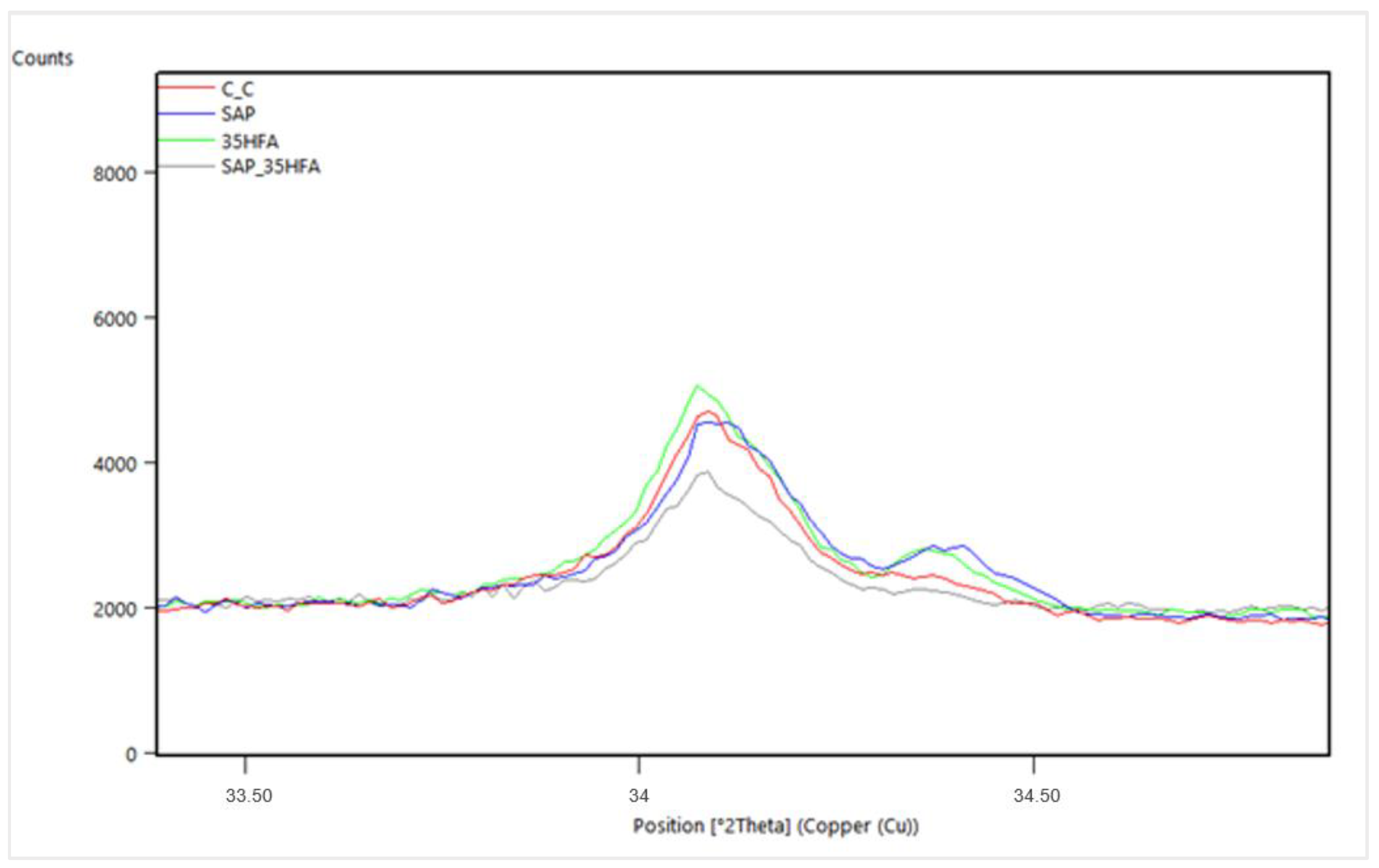
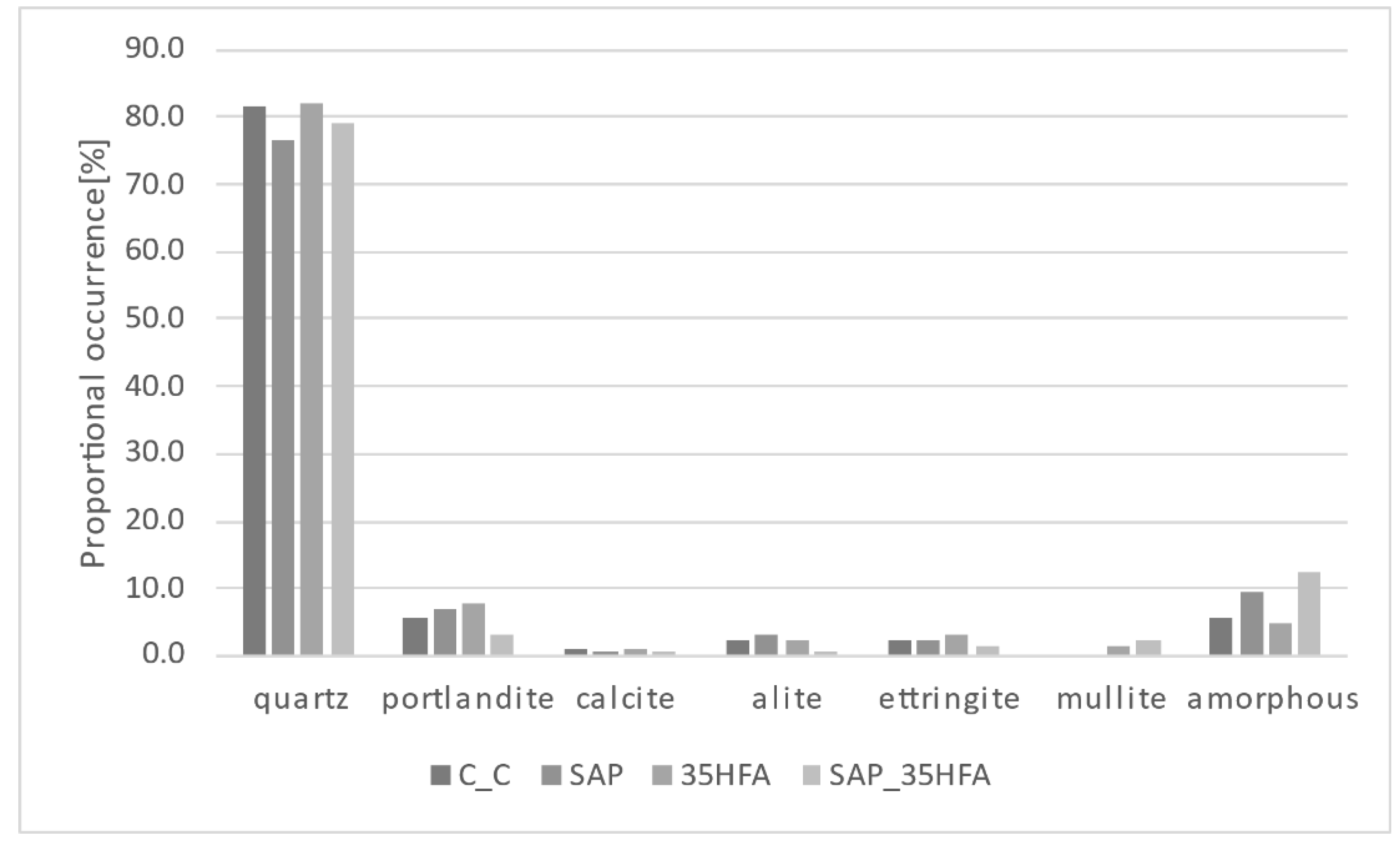
5.5. X-ray Diffraction Analysis
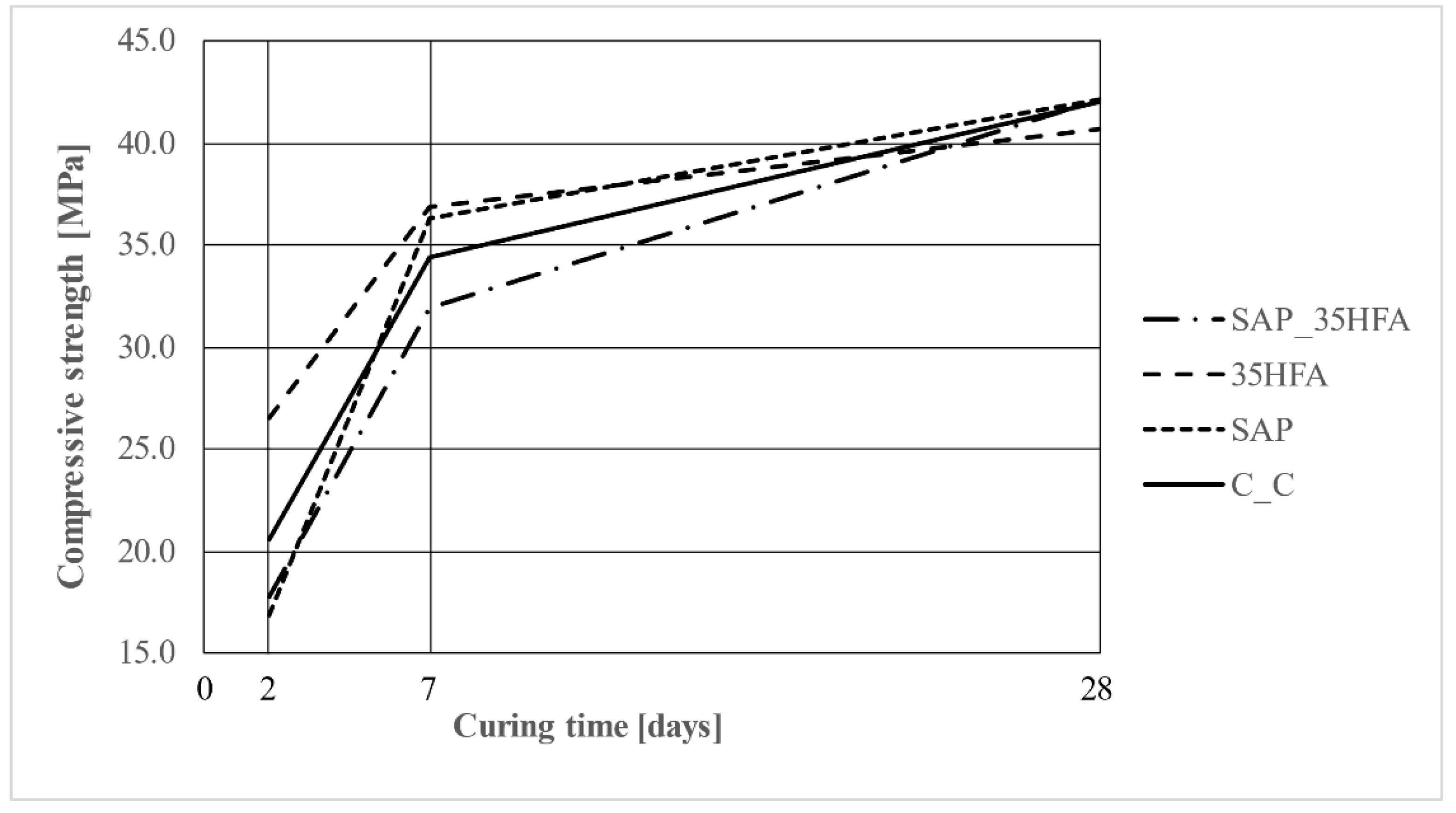
5.6. Compressive Strength
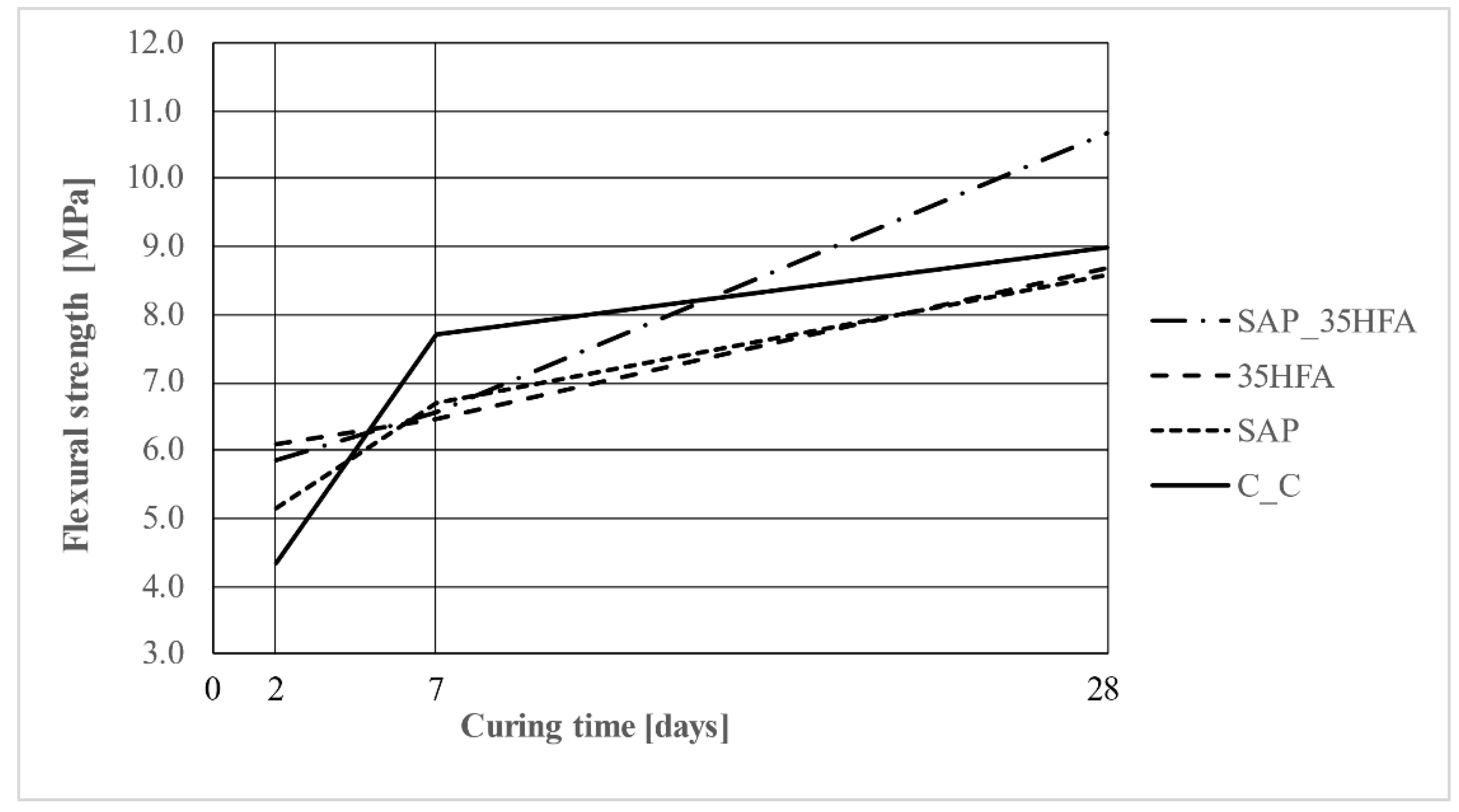
5.7. Flexural Strength
6. Conclusions
- The CEM II binder in combination with SAP and 35 wt.% substitution of cement by HFA can lead to a decrease in the needed amount of Portland clinker by up to 50% (CEM II B-M contains 65–79 w.t% of Portland clinker) while achieving suitable physical–mechanical properties and producing good quality prints. This can be used to produce more environmentally and economically friendly materials.
- The SAP can be used to increase the long-term flexural strength after less than 28 days of curing (which supports the findings of C.J. Adams et al. [39]) and to improve the overall parameters due to the self-curing ability of SAP admixture.
- The addition of SAP can lead to a decrease in early-age physical–mechanical parameters due to the excess of mixing water in the mixture successfully delaying the hydration (the difference between reference mixture and mixtures containing SAP became less marginal after 7 to 28 days of curing).
- Both the SAP and HFA can be used to print 3D structures with smoother surface and less cracks and defects in mortar while preserving the physical–mechanical parameters of 3D printed elements.
- Ultrasonic analysis can be used to sufficiently measure dynamic Young’s modulus of elasticity in a fresh state to visualize the beginning of the hardening process of concrete.
Author Contributions
Funding
Data Availability Statement
Acknowledgments
Conflicts of Interest
References
- Vespalec, A.; Novák, J.; Kohoutková, A.; Vosynek, P.; Podroužek, J.; Škaroupka, D.; Zikmund, T.; Kaiser, J.; Paloušek, D. Interface Behavior and Interface Tensile Strength of a Hardened Concrete Mixture with a Coarse Aggregate for Additive Manufacturing. Materials 2020, 13, 5147. [Google Scholar] [CrossRef] [PubMed]
- Zhang, J.; Wang, J.; Dong, S.; Yu, X.; Han, B. A review of the current progress and application of 3D printed concrete. Compos. Part A Appl. Sci. Manuf. 2019, 125, 105533. [Google Scholar] [CrossRef]
- Nodehi, M.; Aguayo, F.; Nodehi, S.E.; Gholampour, A.; Ozbakkaloglu, T.; Gencel, O. Durability properties of 3D printed concrete (3DPC). Autom. Constr. 2022, 142, 104479. [Google Scholar] [CrossRef]
- Lu, B.; Weng, Y.; Li, M.; Qian, Y.; Leong, K.F.; Tan, M.J.; Qian, S. A systematical review of 3D printable cementitious materials. Constr. Build. Mater. 2019, 207, 477–490. [Google Scholar] [CrossRef]
- De Schutter, G.; Lesage, K.; Mechtcherine, V.; Nerella, V.N.; Habert, G.; Agusti-Juan, I. Vision of 3D printing with concrete—Technical, economic and environmental potentials. Cem. Concr. Res. 2019, 112, 25–36. [Google Scholar] [CrossRef]
- Wolfs, R.J.M.; Bos, F.P.; Salet, T.A.M. Hardened properties of 3D printed concrete: The influence of process parameters on interlayer adhesion. Cem. Concr. Res. 2019, 119, 132–140. [Google Scholar] [CrossRef]
- Nodehi, M.; Ozbakkaloglu, T.; Gholampour, A. Effect of supplementary cementitious materials on properties of 3D printed conventional and alkali-activated concrete: A review. Autom. Constr. 2022, 138, 104215. [Google Scholar] [CrossRef]
- Boscaro, F.; Quadranti, E.; Wangler, T.; Mantellato, S.; Reiter, L.; Flatt, R.J. Eco-Friendly, Set-on-Demand Digital Concrete. 3D Print. Addit. Manuf. 2022, 9, 3–11. [Google Scholar] [CrossRef]
- Chen, Y.; Chang, Z.; He, S.; Çopuroğlu, O.; Šavija, B.; Schlangen, E. Effect of curing methods during a long time gap between two printing sessions on the interlayer bonding of 3D printed cementitious materials. Constr. Build. Mater. 2022, 332, 127394. [Google Scholar] [CrossRef]
- Liu, H.; Liu, C.; Wu, Y.; Bai, G.; He, C.; Zhang, R.; Wang, Y. Hardened properties of 3D printed concrete with recycled coarse aggregate. Cem. Concr. Res. 2022, 159, 106868. [Google Scholar] [CrossRef]
- Zhang, H.; Xiao, J. Plastic shrinkage and cracking of 3D printed mortar with recycled sand. Constr. Build. Mater. 2021, 302, 124405. [Google Scholar] [CrossRef]
- Christen, H.; van Zijl, G.; de Villiers, W. The incorporation of recycled brick aggregate in 3D printed concrete. Clean. Mater. 2022, 4, 100090. [Google Scholar] [CrossRef]
- Skibicki, S.; Pułtorak, M.; Kaszyńska, M.; Hoffmann, M.; Ekiert, E.; Sibera, D. The effect of using recycled PET aggregates on mechanical and durability properties of 3D printed mortar. Constr. Build. Mater. 2022, 335, 127443. [Google Scholar] [CrossRef]
- Ting, G.H.A.; Tay, Y.W.D.; Qian, Y.; Tan, M.J. Utilization of recycled glass for 3D concrete printing: Rheological and mechanical properties. J. Mater. Cycles Waste Manag. 2019, 21, 994–1003. [Google Scholar] [CrossRef]
- Sambucci, M.; Valente, M. Influence of Waste Tire Rubber Particles Size on the Microstructural, Mechanical, and Acoustic Insulation Properties of 3D-Printable Cement Mortars. Civ. Eng. J. 2021, 7, 937–952. [Google Scholar] [CrossRef]
- Ivanova, I.; Ivaniuk, E.; Bisetti, S.; Nerella, V.N.; Mechtcherine, V. Comparison between methods for indirect assessment of buildability in fresh 3D printed mortar and concrete. Cem. Concr. Res. 2022, 1556, 106764. [Google Scholar] [CrossRef]
- Asprone, D.; Menna, C.; Bos, F.P.; Salet, T.A.; Mata-Falcón, J.; Kaufmann, W. Rethinking reinforcement for digital fabrication with concrete. Cem. Concr. Res. 2018, 112, 111–121. [Google Scholar] [CrossRef]
- Yu, K.; McGee, W.; Ng, T.Y.; Zhu, H.; Li, V.C. 3D-printable engineered cementitious composites (3DP-ECC): Fresh and hardened properties. Cem. Concr. Res. 2021, 143, 106388. [Google Scholar] [CrossRef]
- Paul, S.C.; Tay, Y.W.D.; Panda, B.; Tan, M.J. Fresh and hardened properties of 3D printable cementitious materials for building and construction. Arch. Civ. Mech. Eng. 2018, 18, 311–319. [Google Scholar] [CrossRef]
- Nicolas, R.; Richard, B.; Nicolas, D.; Irina, I.; Temitope, K.J.; Dirk, L.; Viktor, M.; Romain, M.; Arnaud, P.; Ursula, P.; et al. Assessing the fresh properties of printable cement-based materials: High potential tests for quality control. Cem. Concr. Res. 2022, 158, 132–140. [Google Scholar] [CrossRef]
- Napolitano, R.; Forni, D.; Menna, C.; Asprone, D.; Cadoni, E. Dynamic characterization of the layer-interface properties of 3D-printed concrete elements. Case Stud. Constr. Mater. 2021, 15, e00780. [Google Scholar] [CrossRef]
- Mechtcherine, V.; Secrieru, E.; Schröfl, C. Effect of superabsorbent polymers (SAPs) on rheological properties of fresh cement-based mortars — Development of yield stress and plastic viscosity over time. Cem. Concr. Res. 2015, 67, 52–65. [Google Scholar] [CrossRef]
- Danish, A.; Mosaberpanah, M.A.; Salim, M.U. Robust evaluation of superabsorbent polymers as an internal curing agent in cementitious composites. J. Mater. Sci. 2021, 56, 136–172. [Google Scholar] [CrossRef]
- Mechtcherine, V. Use of superabsorbent polymers (SAP) as concrete additive. RILEM Tech. Lett. 2016, 1, 81–87. [Google Scholar] [CrossRef]
- Rostami, R.; Klemm, A.J.; Almeida, F.C. Reduction of shrinkage by Superabsorbent polymers (SAP) in fibre reinforced mortars. Constr. Build. Mater. 2021, 288, 123109. [Google Scholar] [CrossRef]
- EN 1015-3; Methods of Test for Mortar for Masonry—Part 3: Determination of Consistence of Fresh Mortar. European Committee for Standardization: Brussels, Belgium, 1999.
- EN 1015-6:1998/A1:2006; Methods of Test for Mortar for Masonry—Part 6: Determination of Bulk Density of Fresh Mortar. European Committee for Standardization: Brussels, Belgium, 2006.
- EN 1015-10:2001; Methods of Test for Mortar for Masonry—Part 10: Determination of Dry Bulk Density of Hardened Mortar. European Committee for Standardization: Brussels, Belgium, 2001.
- EN 12504-4; Testing Concrete—Part 4: Determination of Ultrasonic Pulse Velocity. European Committee for Standardization: Brussels, Belgium, 2021.
- ČSN 73 1371; Non-Destructive Testing of Concrete—Method of Ultrasonic Pulse Testing of Concrete. European Committee for Standardization: Brussels, Belgium, 2011.
- Montanari, L.; Suraneni, P.; Weiss, W.J. Accounting for Water Stored in Superabsorbent Polymers in Increasing the Degree of Hydration and Reducing the Shrinkage of Internally Cured Cementitious Mixtures. Adv. Civ. Eng. Mater. 2017, 6, 583–599. [Google Scholar] [CrossRef]
- He, Z.; Shen, A.; Guo, Y.; Lyu, Z.; Li, D.; Qin, X.; Zhao, M.; Wang, Z. Cement-based materials modified with superabsorbent polymers: A review. Constr. Build. Mater. 2019, 225, 569–590. [Google Scholar] [CrossRef]
- Long, W.-J.; Tao, J.-L.; Lin, C.; Gu, Y.-C.; Mei, L.; Duan, H.-B.; Xing, F. Rheology and buildability of sustainable cement-based composites containing micro-crystalline cellulose for 3D-printing. J. Clean. Prod. 2019, 239, 118054. [Google Scholar] [CrossRef]
- Fitzka, M.; Karr, U.; Granzner, M.; Melichar, T.; Rödhammer, M.; Strauss, A.; Mayer, H. Ultrasonic fatigue testing of concrete. Ultrasonics 2021, 116, 106521. [Google Scholar] [CrossRef]
- Liu, J.; Setunge, S.; Tran, P. 3D concrete printing with cement-coated recycled crumb rubber: Compressive and microstructural properties. Constr. Build. Mater. 2022, 347, 128507. [Google Scholar] [CrossRef]
- Ramezani, M.; Kim, Y.H.; Sun, Z. Mechanical properties of carbon-nanotube-reinforced cementitious materials: Database and statistical analysis. Mag. Concr. Res. 2020, 72, 1047–1071. [Google Scholar] [CrossRef]
- Ramezani, M.; Kim, Y.H.; Sun, Z. Modeling the mechanical properties of cementitious materials containing CNTs. Cem. Concr. Compos. 2019, 104, 103347. [Google Scholar] [CrossRef]
- Xu, Z.; Zhang, D.; Li, H.; Sun, X.; Zhao, K.; Wang, Y. Effect of FA and GGBFS on compressive strength, rheology, and printing properties of cement-based 3D printing material. Constr. Build. Mater. 2022, 339, 127685. [Google Scholar] [CrossRef]
- Adams, C.J.; Bose, B.; Mann, E.; Erk, K.A.; Behnood, A.; Castillo, A.; Rodriguez, F.B.; Wang, Y.; Olek, J. Superabsorbent Polymers for Internally Cured Concrete (Joint Transportation Research Program Publication No. FHWA/IN/JTRP-2022/04); Purdue University: West Lafayette, IN, USA, 2022. [Google Scholar] [CrossRef]


| Specific Surface Area [m2/kg] | Setting Initiation [min] | Final Setting Time [min] | Volume Stability [mm] | Compressive Strength [N/mm2] | Flexural Strength [N/mm2] | ||||
|---|---|---|---|---|---|---|---|---|---|
| 2 Days | 28 Days | 2 Days | 28 Days | ||||||
| 524 | 247 | 328 | 0.7 | 20.4 | 47.4 | 4.7 | 8.1 | ||
| Chemical Composition | |||||||||
| SiO2 [%] | Al2O3 [%] | Fe2O3 [%] | CaO [%] | MgO [%] | K2O [%] | Na2O [%] | SO3 [%] | Na2O eq. [%] | Cl [%] |
| 20.26 | 4.82 | 2.72 | 58.28 | 2.25 | 0.77 | 0.1 | 2.6 | 0.61 | 0.054 |
| Particle Size [µm] | C_A [wt.%] | C_B [wt.%] | C_C [wt.%] |
|---|---|---|---|
| 1000–2000 | 61.24 | 76.86 | 68.59 |
| 500–1000 | 33.53 | 53.02 | 43.02 |
| 250–500 | 22.03 | 42.03 | 32.45 |
| 125–250 | 4.66 | 17.06 | 12.65 |
| 63–125 | 0.75 | 3.90 | 2.88 |
| 0–63 | 0.00 | 0.00 | 0.00 |
| SiO2 [%] | Al2O3 [%] | Fe2O3 [%] | CaO [%] | MgO [%] | K2O [%] | Na2O [%] | SO3 [%] |
|---|---|---|---|---|---|---|---|
| 50.0 | 26.4 | 5.9 | 0.4 | 1.5 | 1.1 | 0.2 | 0.1 |
| Component | C_A | C_B | C_C | SAP | 35HFA | SAP_35HFA |
|---|---|---|---|---|---|---|
| Cement | 300.00 | 300.00 | 300.00 | 300.00 | 195.00 | 195.00 |
| Silica sand 0.1–0.35 mm | 173.00 | 171.00 | 148.00 | 148.00 | 148.00 | 148.00 |
| Silica sand 0.3–1.0 mm | 204.00 | 194.00 | 174.00 | 174.00 | 174.00 | 174.00 |
| Silica sand 1.0–2.0 mm | 320.70 | 190.10 | 270.90 | 270.90 | 270.90 | 270.90 |
| Quartz dust | - | 142.60 | 104.80 | 104.47 | 104.80 | 104.57 |
| PCE water reducer | 0.30 | 0.30 | 0.30 | 0.30 | 0.30 | 0.30 |
| Defoaming agent | 2.00 | 2.00 | 2.00 | 2.00 | 2.00 | 2.00 |
| SAP | - | - | - | 0.33 | - | 0.23 |
| HFA | - | - | - | - | 105.00 | 105.00 |
| Water | 129.00 | 140.00 | 134.00 | 156.10 | 127.80 | 142.00 |
| Sample | cf [kg/m3] | cs [mL/g] | αmax [-] | φSAP,30 [g/g] | MSAP [kg/m3] |
|---|---|---|---|---|---|
| C_C | 660 | 0.19 | 0.56 | - | 0 |
| SAP | 660 | 0.19 | 0.56 | 65 | 1.1 |
| 35HFA | 430 | 0.15 | 0.64 | - | 0 |
| SAP_35HFA | 430 | 0.15 | 0.64 | 65 | 0.6 |
| Sample | Fresh State [kg/m3] | 2 Days of Curing [kg/m3] | 7 Days of Curing [kg/m3] | 28 Days of Curing [kg/m3] |
|---|---|---|---|---|
| C_C | 2200 | 2210 | 2230 | 2230 |
| SAP | 2140 | 2140 | 2170 | 2170 |
| 35HFA | 2160 | 2160 | 2180 | 2180 |
| SAP_35HFA | 2110 | 2110 | 2170 | 2170 |
Publisher’s Note: MDPI stays neutral with regard to jurisdictional claims in published maps and institutional affiliations. |
© 2022 by the authors. Licensee MDPI, Basel, Switzerland. This article is an open access article distributed under the terms and conditions of the Creative Commons Attribution (CC BY) license (https://creativecommons.org/licenses/by/4.0/).
Share and Cite
Melichar, J.; Žižková, N.; Brožovský, J.; Mészárosová, L.; Hermann, R. Study of the Interaction of Cement-Based Materials for 3D Printing with Fly Ash and Superabsorbent Polymers. Buildings 2022, 12, 2008. https://doi.org/10.3390/buildings12112008
Melichar J, Žižková N, Brožovský J, Mészárosová L, Hermann R. Study of the Interaction of Cement-Based Materials for 3D Printing with Fly Ash and Superabsorbent Polymers. Buildings. 2022; 12(11):2008. https://doi.org/10.3390/buildings12112008
Chicago/Turabian StyleMelichar, Jindřich, Nikol Žižková, Jiří Brožovský, Lenka Mészárosová, and Radek Hermann. 2022. "Study of the Interaction of Cement-Based Materials for 3D Printing with Fly Ash and Superabsorbent Polymers" Buildings 12, no. 11: 2008. https://doi.org/10.3390/buildings12112008
APA StyleMelichar, J., Žižková, N., Brožovský, J., Mészárosová, L., & Hermann, R. (2022). Study of the Interaction of Cement-Based Materials for 3D Printing with Fly Ash and Superabsorbent Polymers. Buildings, 12(11), 2008. https://doi.org/10.3390/buildings12112008