

Modelling of Strengthened Steel Connections under Static and Cyclic Loading


Abstract
:1. Introduction
2. Mechanical Characterisation and Material Properties
2.1. Constitutive Equations
2.2. Identification Procedure
- (a)
- Elastic properties
- (b)
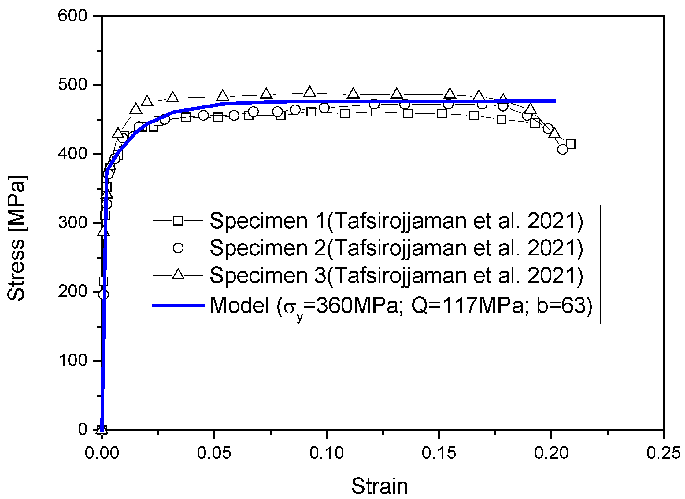
- Plastic properties
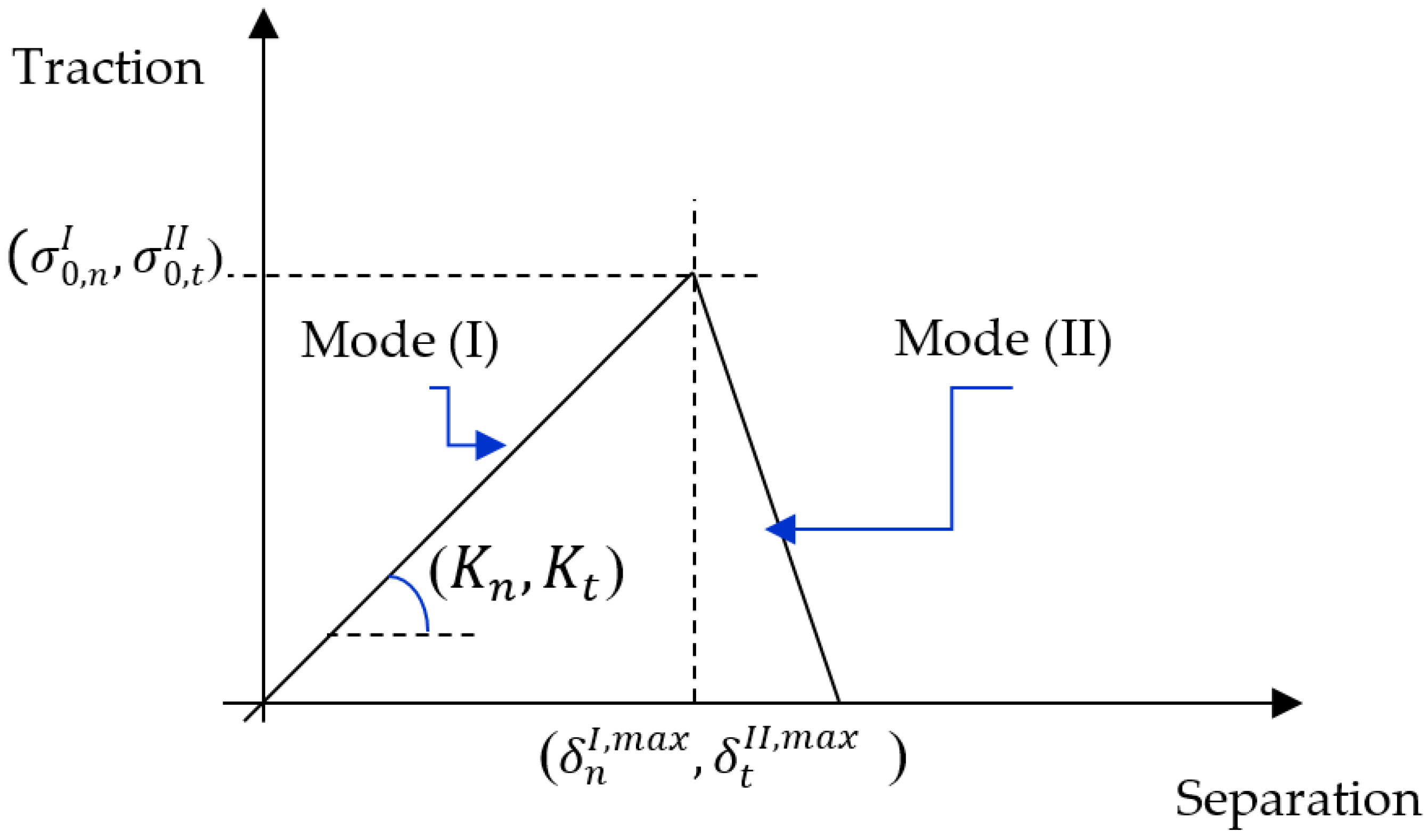
2.3. Cohesive Zone Model CZM
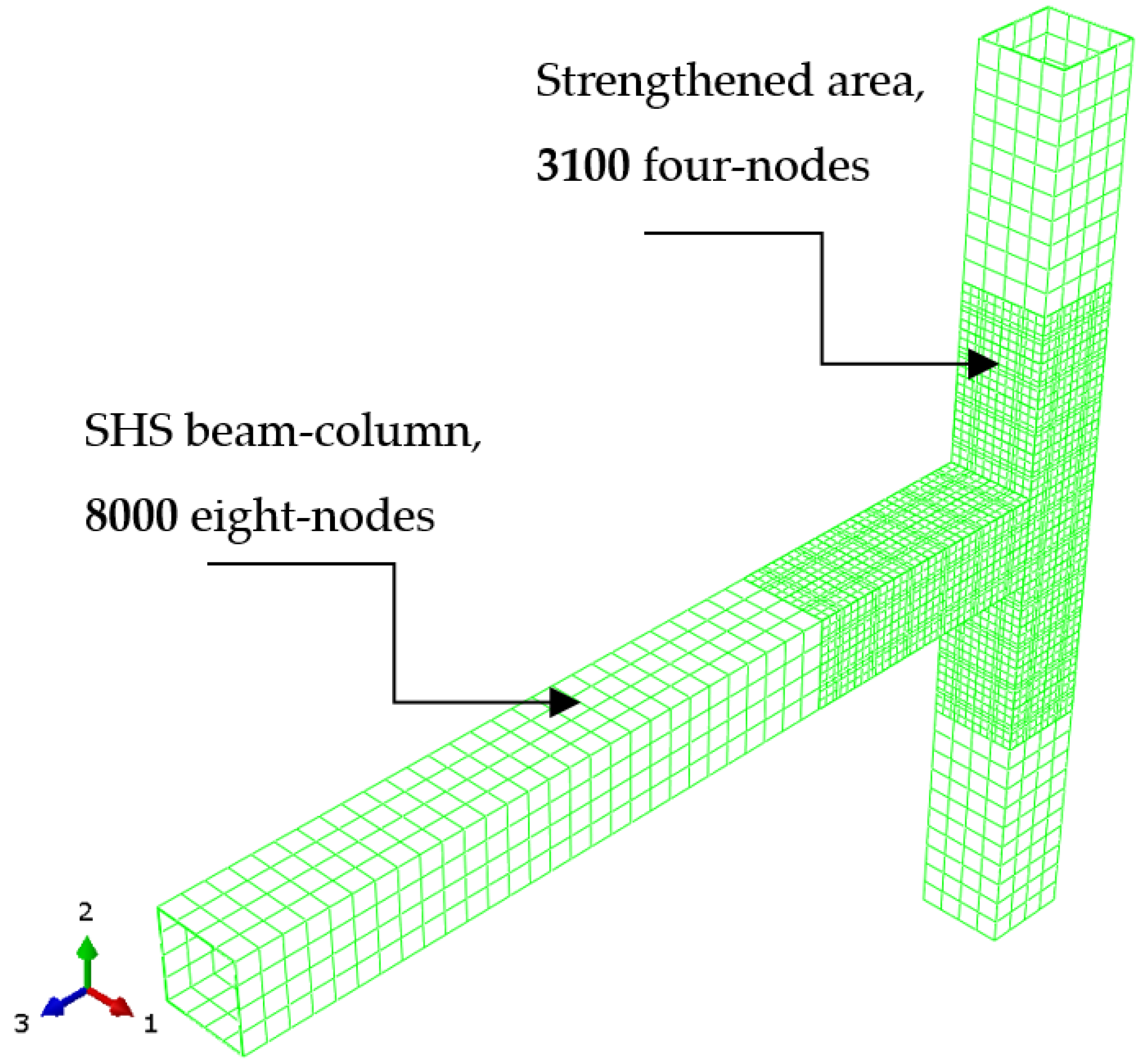
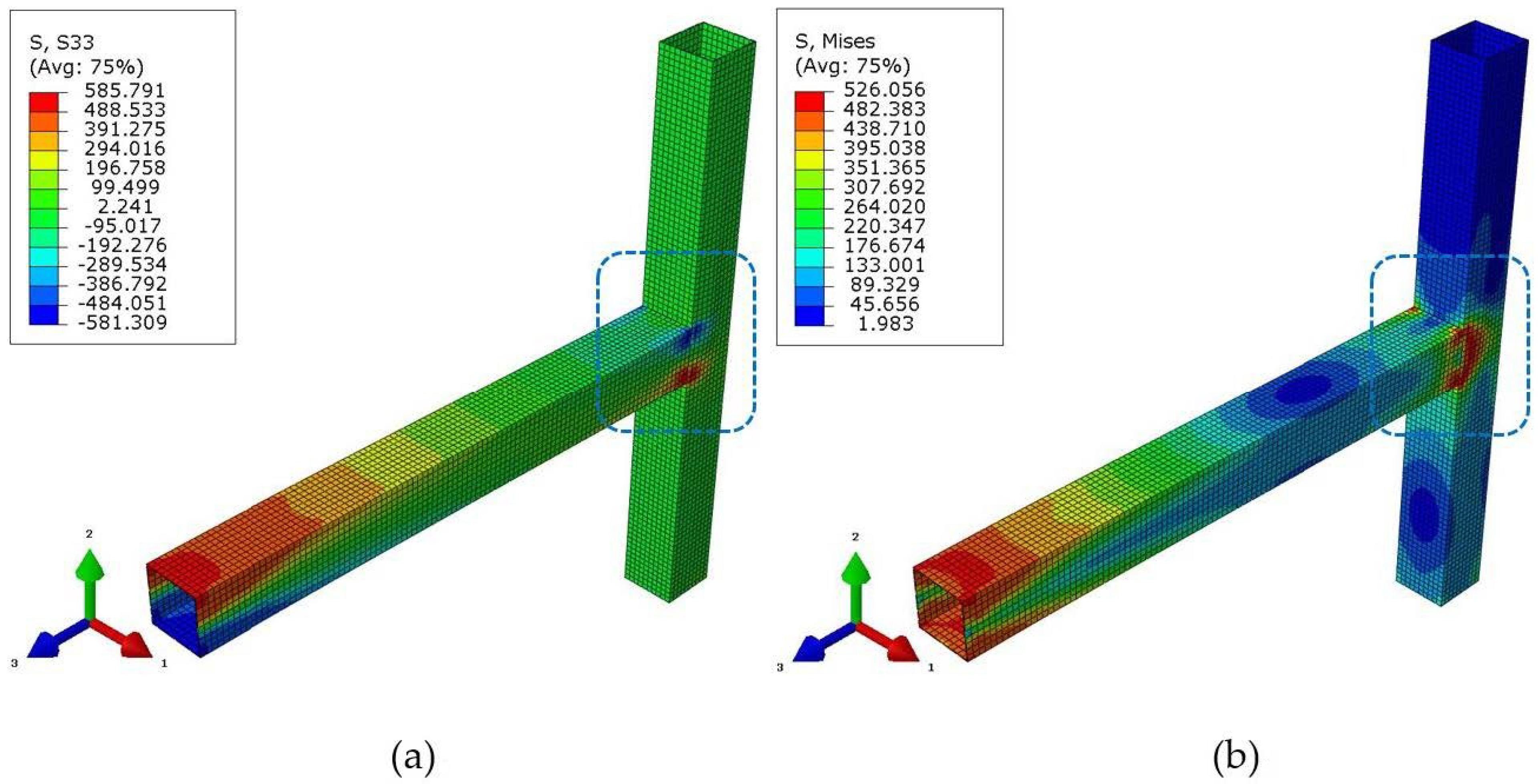
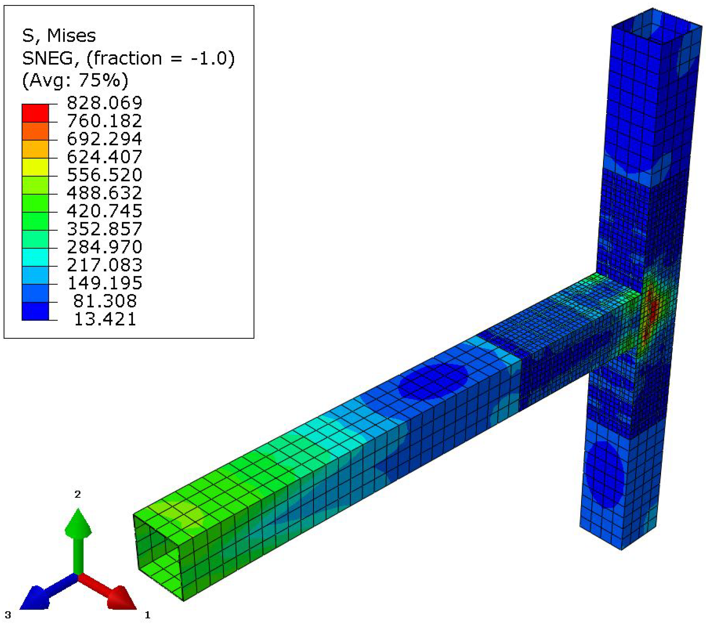
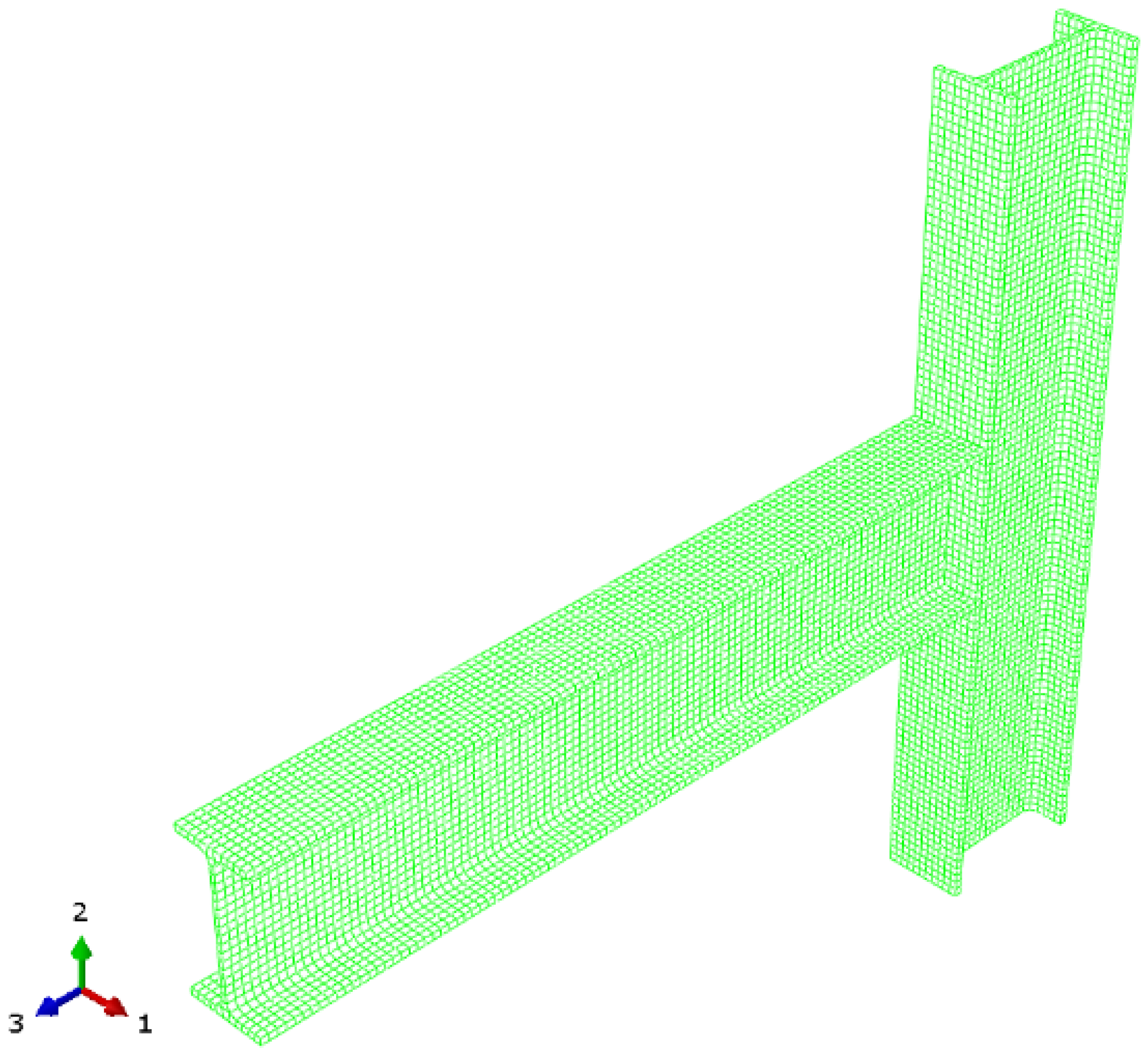
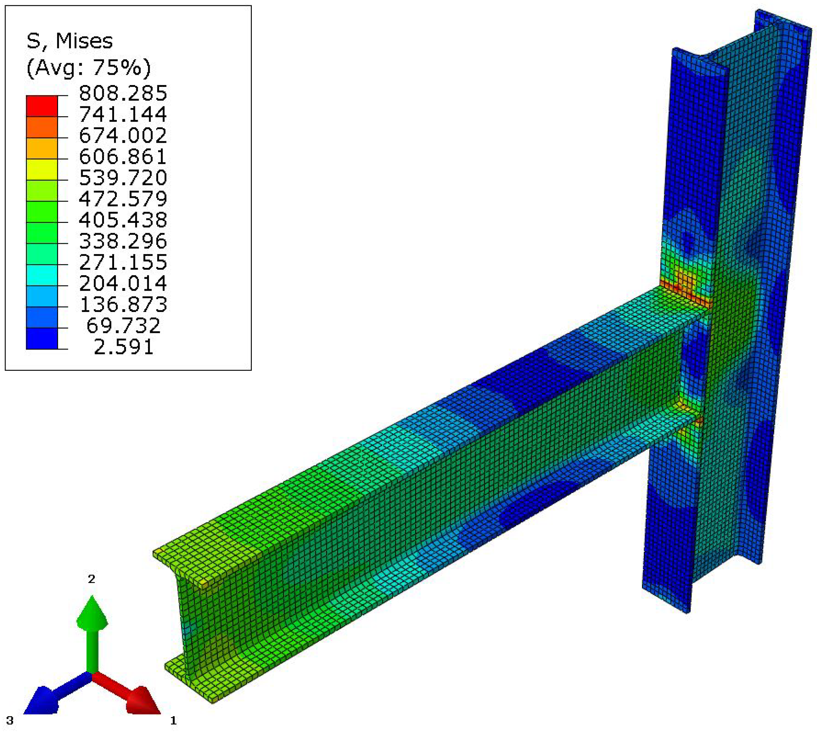
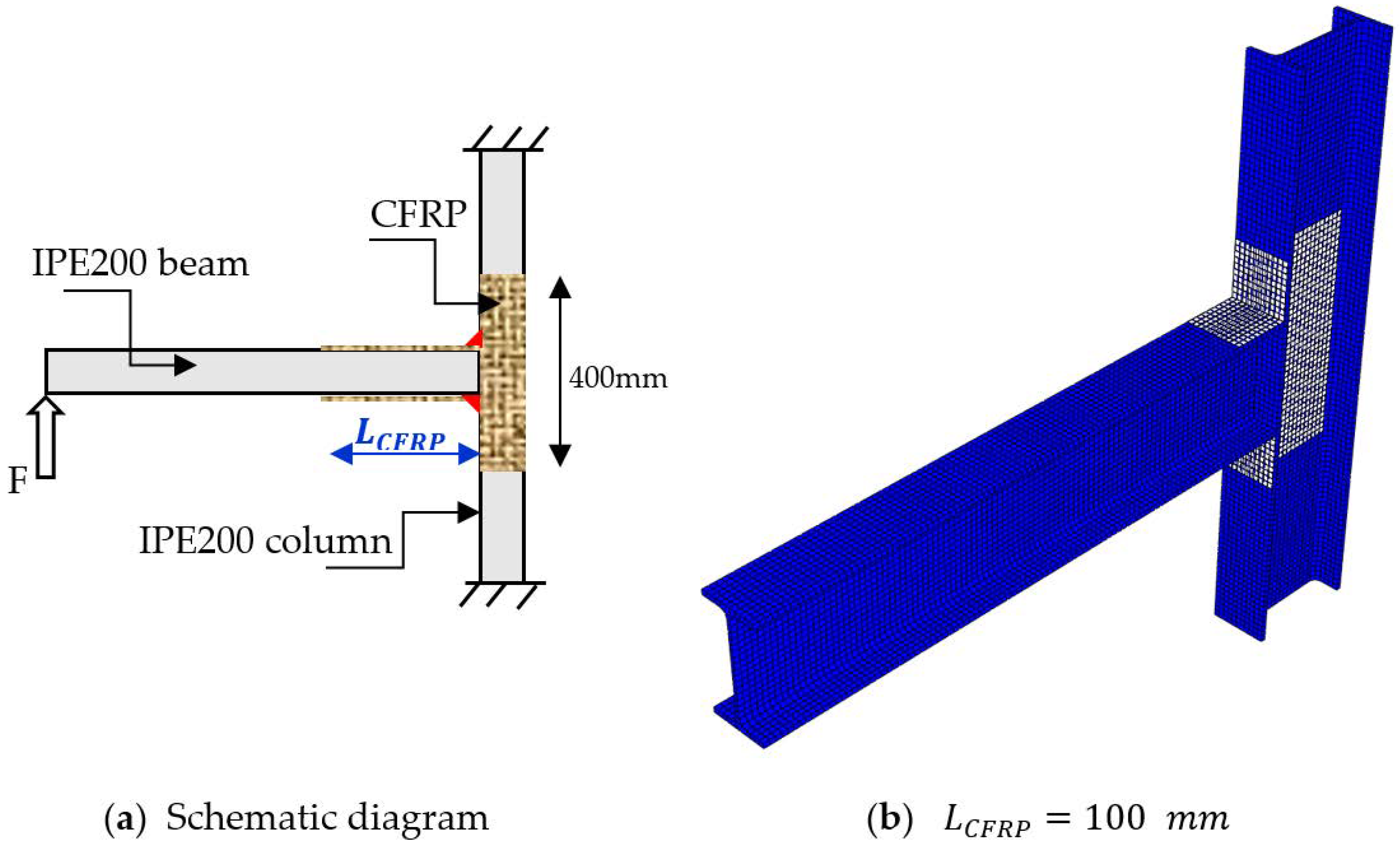
3. Finite Element Modelling
4. Validation
4.1. Under Monotonic Loading
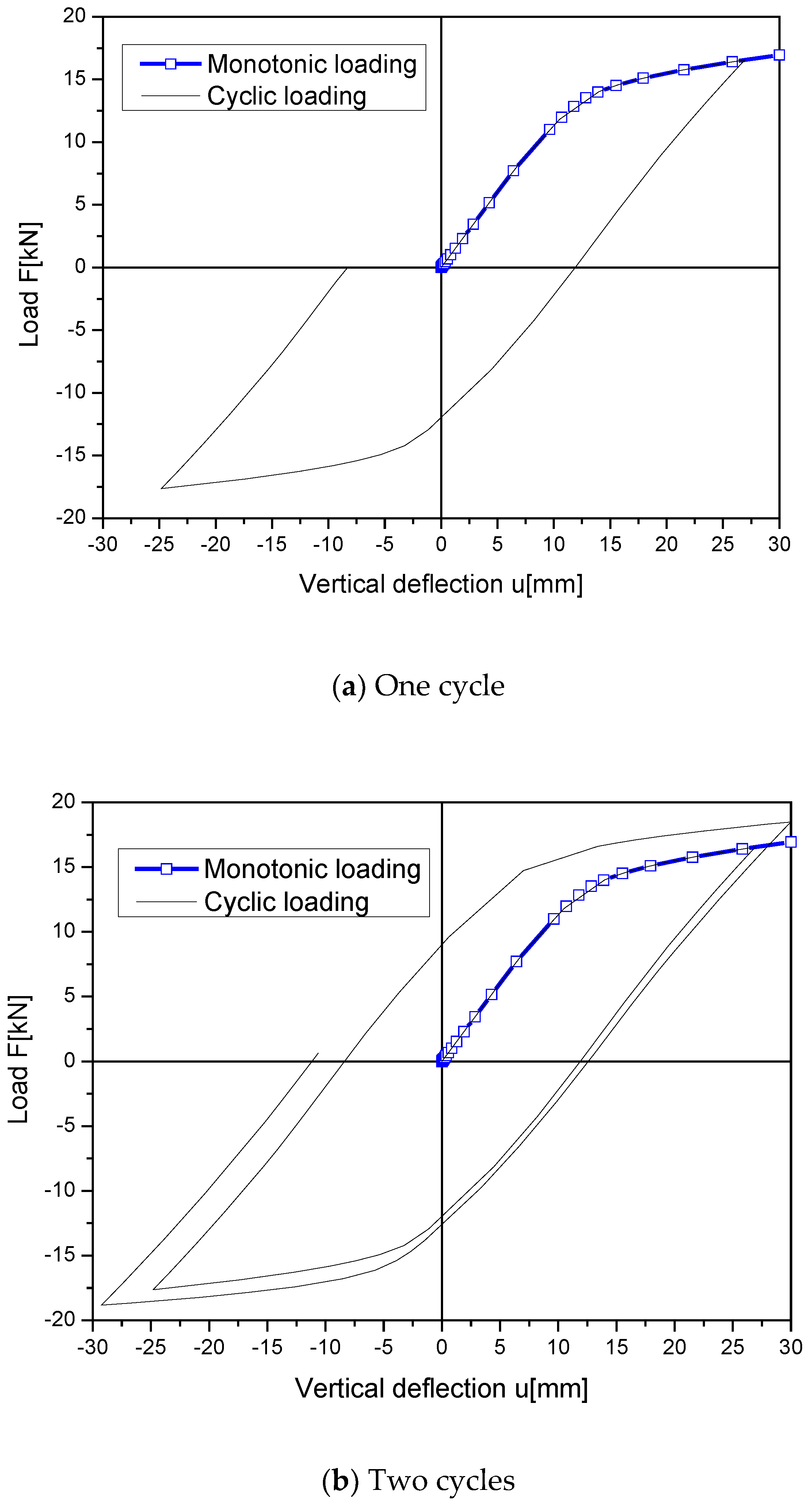
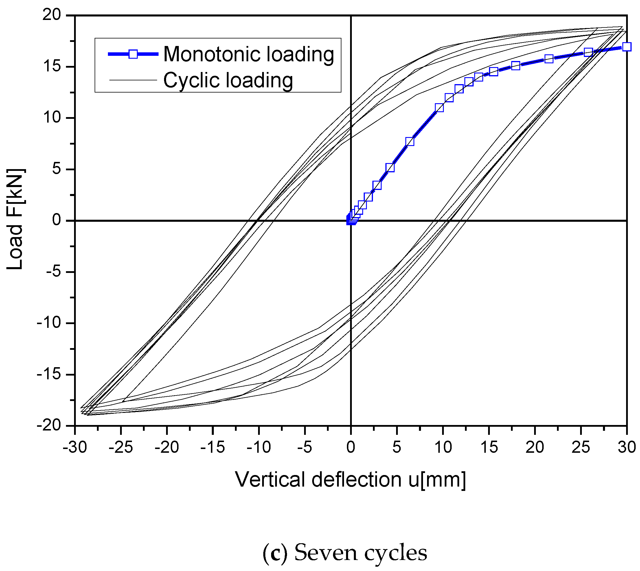
4.2. Under Cyclic Loading
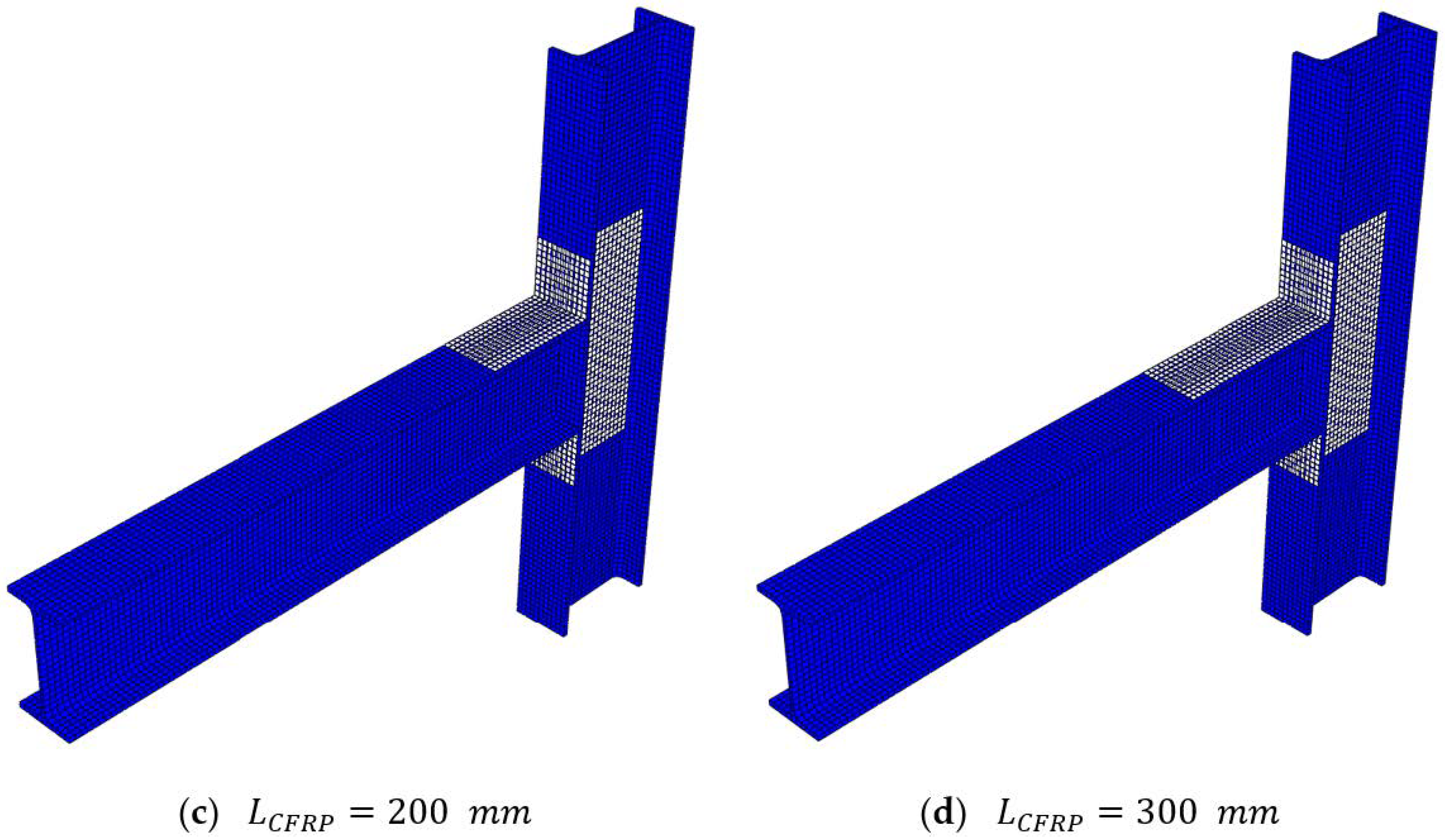
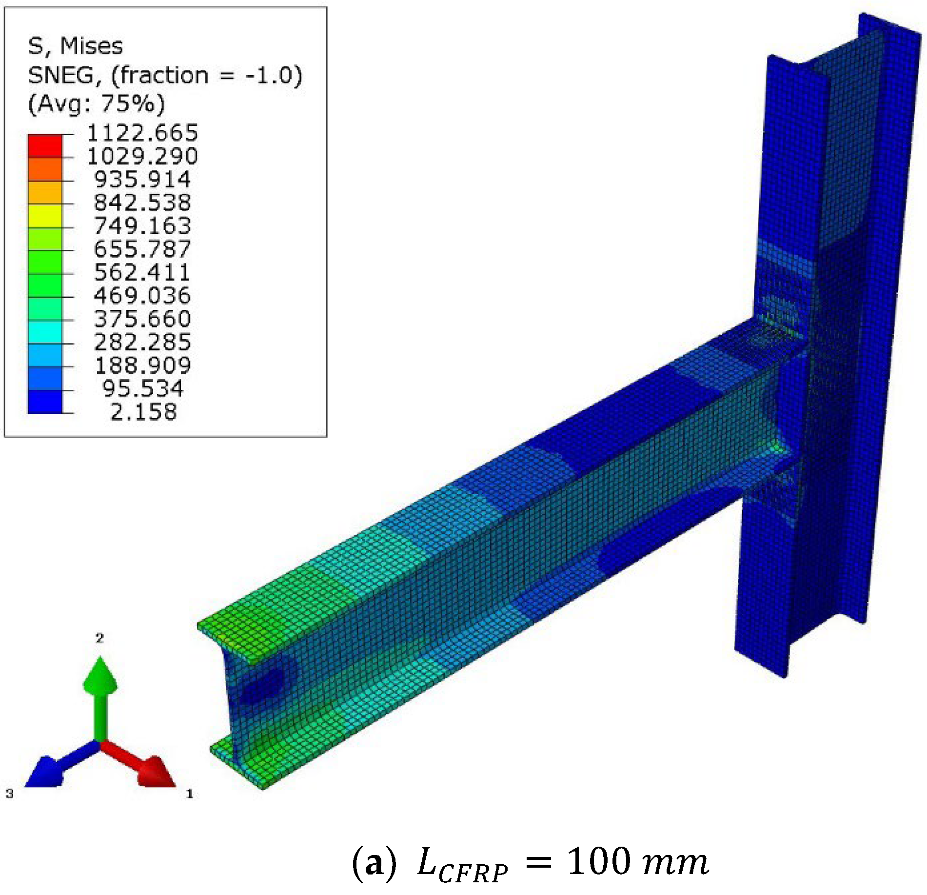
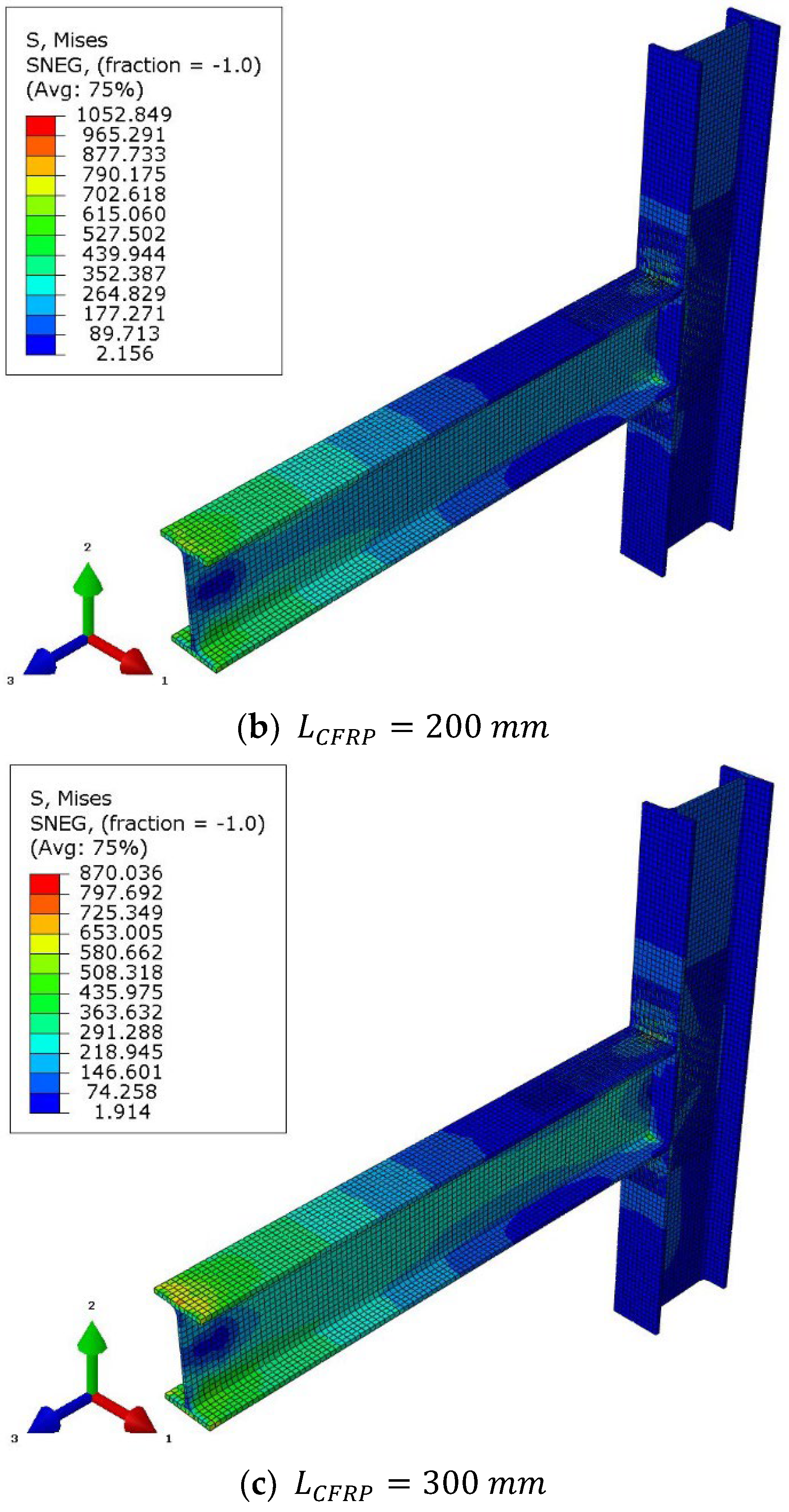
5. Parametric Study
6. Conclusions
- Numerical modelling of the cyclic behaviour of FRP strengthened steel connections is rarely presented in the literature compared to other civil engineering structures such as reinforced concrete and timber structures.
- The developed numerical procedure complements the experimental work of Tafsirojjaman et al. [1];
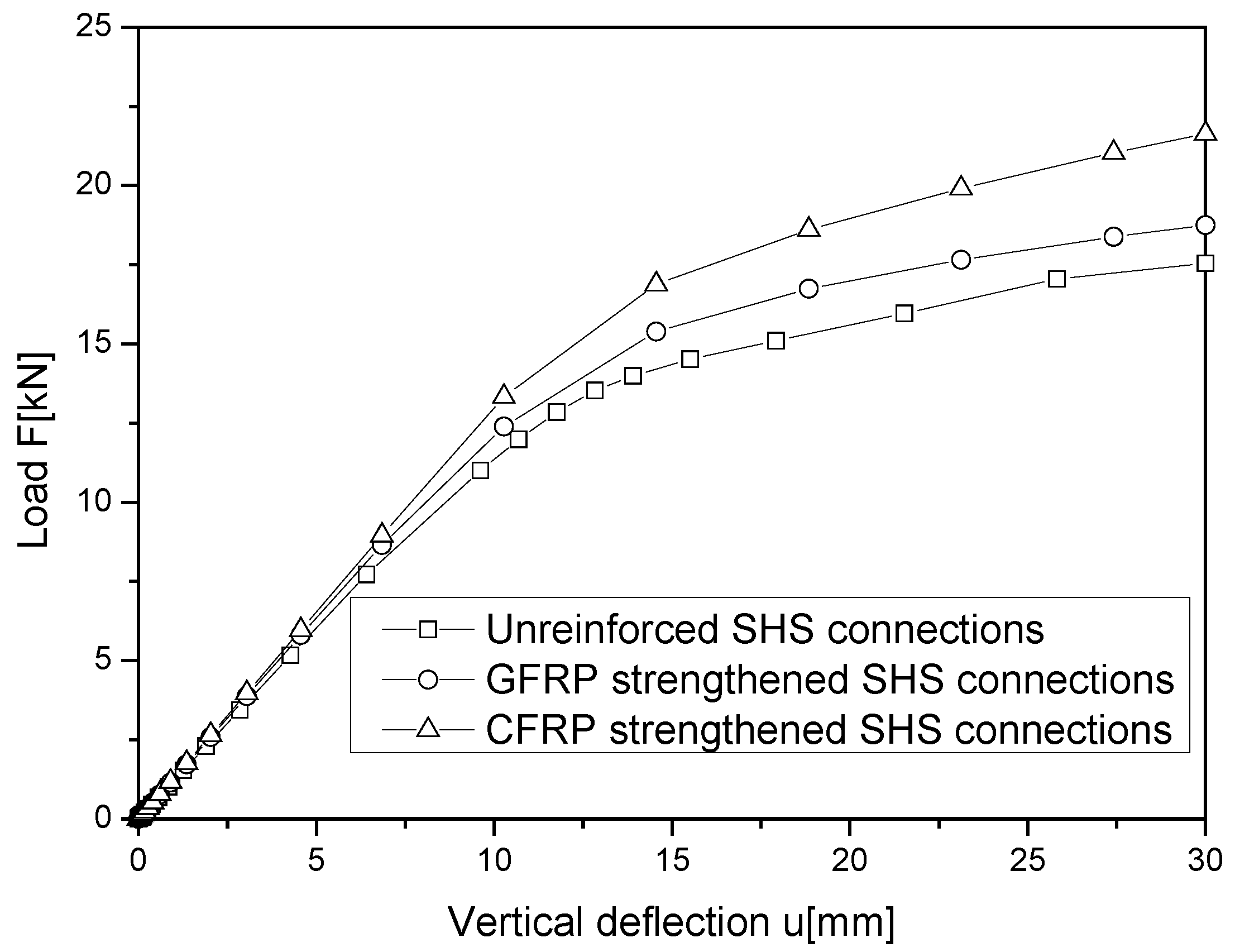
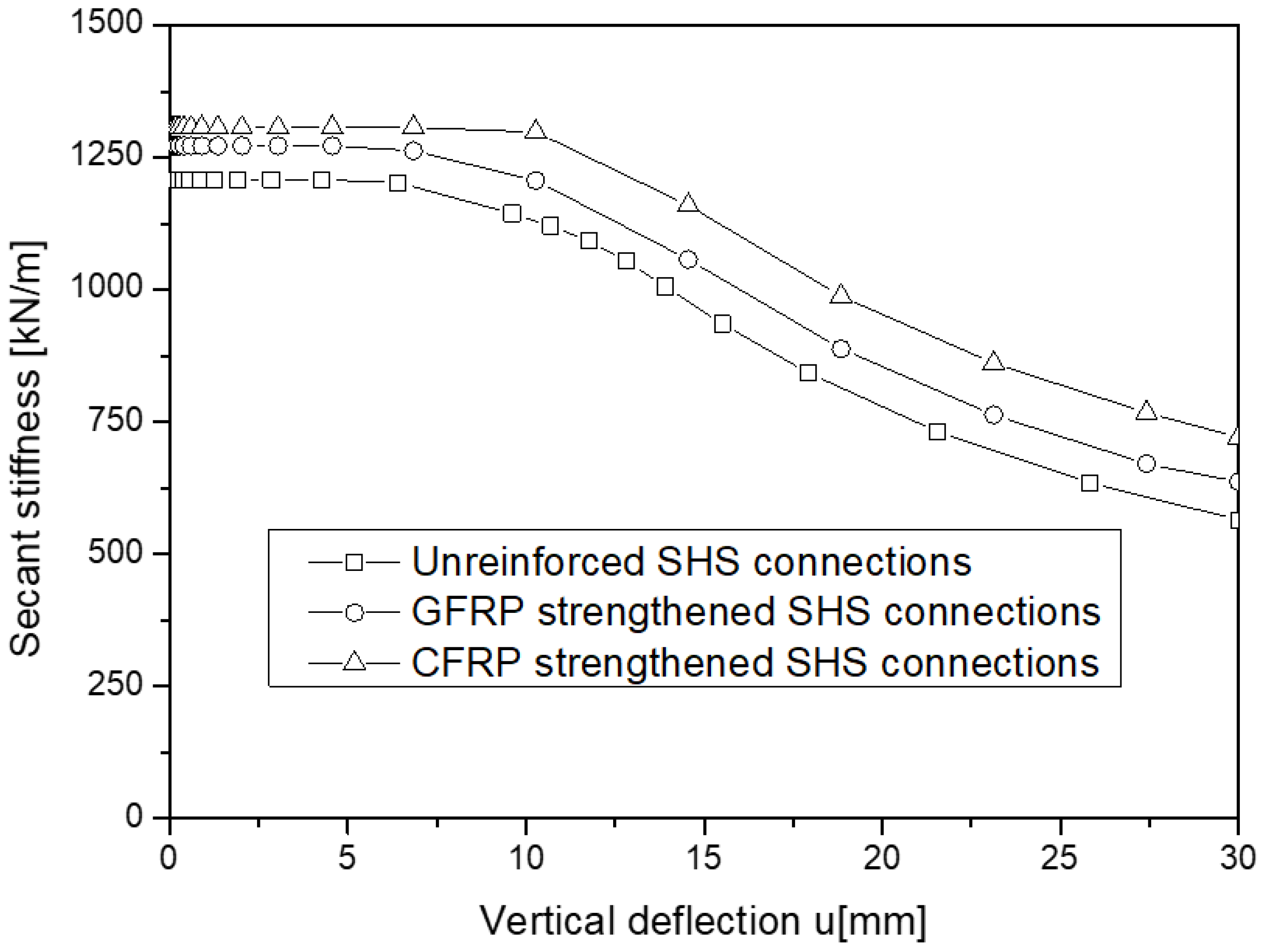
- The parametric analysis revealed that strengthening a connection with I-sections is not as effective as strengthening a connection with square hollow sections (SHS). In the latter, a simple bonding of a 0.6 mm thick CFRP laminate resulted in a considerable increase in the capacity of the connection; that is: an improvement of 14.85% in mechanical resistance using GFRP and 27% using CFRP.
Author Contributions
Funding
Institutional Review Board Statement
Informed Consent Statement
Data Availability Statement
Conflicts of Interest
References
- Tafsirojjaman, T.; Fawzia, S.; Thambiratnam, D.; Zhao, X.-L. Behaviour of CFRP strengthened CHS members under monotonic and cyclic loading. Compos. Struct. 2019, 220, 592–601. [Google Scholar] [CrossRef]
- Tafsirojjaman, T.; Fawzia, S.; Thambiratnam, D.P.; Zhao, X.-L. FRP strengthened SHS beam-column connection under monotonic and large-deformation cyclic loading. Thin-Walled Struct. 2021, 161, 107–518. [Google Scholar] [CrossRef]
- Khelifa, M.; Celzard, A.; Oudjene, M.; Ruelle, J. Experimental and numerical analysis of CFRP-strengthened finger-jointed timber beams. Int. J. Adhes. Adhes. 2016, 68, 283–297. [Google Scholar] [CrossRef]
- Alhamdan, Y.; Dirikgil, T. Experimental Investigation of the Flexural Strengthening of Fixed-Supported RC. Int. J. Civ. Eng. 2020, 18, 1229–1246. [Google Scholar] [CrossRef]
- Hu, L.; Feng, P.; Zhao, X.L. Fatigue design of CFRP strengthened steel members. Thin-Walled Struct. 2017, 119, 482–498. [Google Scholar] [CrossRef]
- Siddique, M.A.A.; El Damatty, A.A.; El Ansary, A.M. A numerical investigation of over strength and ductility factors of moment resisting steel frames retrofitted with GFRP plates. Can. J. Civ. Eng. 2014, 41, 17–31. [Google Scholar] [CrossRef]
- Feng, P.; Hu, L.; Zhao, X.-L.; Cheng, L.; Xu, S. Study on thermal effects on fatigue behavior of cracked steel plates strengthened by CFRP sheets. Thin-Walled Struct. 2014, 82, 311–320. [Google Scholar] [CrossRef]
- Bambach, M.R.; Elchalakani, M. Plastic mechanism analysis of steel SHS strengthened with CFRP under large axial deformation. Thin-Walled Struct. 2007, 45, 159–170. [Google Scholar] [CrossRef]
- Wang, M.; Shi, Y.; Wang, Y.; Shi, G. Numerical study on seismic behaviors of steel frame end-plate connections. J. Constr. Steel Res. 2013, 90, 140–152. [Google Scholar] [CrossRef]
- Fryba, L.; Urushadze, S. Improvement of fatigue properties or orthotropic decks. Eng. Struct. 2011, 33, 1166–1169. [Google Scholar] [CrossRef]
- Si Larbi, A.; Ferrier, E.; Jurkiewiez, B.; Hamelin, P. Static behaviour of steel concrete beam connected by bonding. Eng. Struct. 2007, 29, 1034–1042. [Google Scholar] [CrossRef]
- Teng, J.G.; Yu, T.; Fernando, D. Strengthening of steel structures with fiber-reinforced polymer composites. J. Constr. Steel Res. 2012, 78, 131–143. [Google Scholar] [CrossRef]
- Bui, T.Q.; Hu, X. A review of phase-field models, fundamentals and their applications to composite laminates. Eng. Fract. Mech. 2021, 248, 107705. [Google Scholar] [CrossRef]
- Cao, Y.; Cao, Z.; Zhao, Y.; Zuo, D.; Tay, T.E. Damage progression and failure of single-lap thin-ply laminated composite bolted joints under quasi-static loading. Int. J. Mech. Sci. 2020, 170, 105360. [Google Scholar] [CrossRef]
- Zhang, P.; Yao, W.; Hu, X.; Bui, T.Q. 3D micromechanical progressive failure simulation for fiber-reinforced composites. Compos. Struct. 2020, 249, 112534. [Google Scholar] [CrossRef]
- Yin, B.B.; Zhang, L.W. Phase field method for simulating the brittle fracture of fiber reinforced composites. Eng. Fract. Mech. 2019, 211, 321–340. [Google Scholar] [CrossRef]
- Ülger, T.; Sharifi, A.S. Numerical Performance Analysis of Concrete-Filled Hollow GFRP Beams including Inner Surface Bearing Stresses at the Interface. Buildings 2022, 12, 1340. [Google Scholar] [CrossRef]
- Abaqus Dassault Systèmes Simulia Corp: Providence, RI, USA. 2020. Available online: https://www.3ds.com/products-services/simulia/products/abaqus/ (accessed on 16 August 2022).
- Khelifa, M.; Vila Loperena, N.; Bleron, L.; Khennane, A. Analysis of CFRP strengthened timber beams. J. Adhes. Sci. Technol. 2014, 28, 1–14. [Google Scholar] [CrossRef]
- Hill, R. A new method for determining the yield criterion and plastic potential of ductile metals. J. Mech. Phys. Solids. 1953, 1, 271–276. [Google Scholar] [CrossRef]


| Steel | FRP | Adhesive (*) | ||
|---|---|---|---|---|
| Elasticity | Plasticity | GFRP | CFRP | |
| ; = 0.3 | ; ; ; | ; ; ; | ||
Publisher’s Note: MDPI stays neutral with regard to jurisdictional claims in published maps and institutional affiliations. |
© 2022 by the authors. Licensee MDPI, Basel, Switzerland. This article is an open access article distributed under the terms and conditions of the Creative Commons Attribution (CC BY) license (https://creativecommons.org/licenses/by/4.0/).
Share and Cite
Khelifa, M.; Khennane, A.; Oudjene, M. Modelling of Strengthened Steel Connections under Static and Cyclic Loading. Buildings 2022, 12, 1962. https://doi.org/10.3390/buildings12111962
Khelifa M, Khennane A, Oudjene M. Modelling of Strengthened Steel Connections under Static and Cyclic Loading. Buildings. 2022; 12(11):1962. https://doi.org/10.3390/buildings12111962
Chicago/Turabian StyleKhelifa, Mourad, Amar Khennane, and Marc Oudjene. 2022. "Modelling of Strengthened Steel Connections under Static and Cyclic Loading" Buildings 12, no. 11: 1962. https://doi.org/10.3390/buildings12111962
APA StyleKhelifa, M., Khennane, A., & Oudjene, M. (2022). Modelling of Strengthened Steel Connections under Static and Cyclic Loading. Buildings, 12(11), 1962. https://doi.org/10.3390/buildings12111962