Abstract
For the mechanical analysis work in the structural design phase, data conversion and information transfer between BIM model and finite element model have become the main factors limiting its efficiency and quality, with the development of BIM (building information modeling) technology application in the whole life cycle. The combined application of BIM and ontology technology has promoted the automation of compliance checking, cost management, green building evaluation, and many other fields. Based on OpenBIM, this study combines IFC (Industry Foundation Classes) and the ontology system and proposes an automatic generation method for converting BIM to the finite element model. Firstly, the elements contained in the finite element model are generalized and the information set requirement, to be extracted or inferred from BIM for the generation of the finite element model, is obtained accordingly. Secondly, the information extraction technical route is constructed to satisfy the acquisition of the information set, including three main aspects, i.e., IFC-based material information, spatial information, and other basic information; ontology-based finite element cell selection method; and APDL statement generation methods based on JAVA, C#, etc. Finally, a complete technical route and a software architecture, designed for converting BIM to the finite element model, are derived. To assess the feasibility of the method, a simple structure is tested in this paper, and the result indicates that the automatic decision-making reasoning mechanism of constructing element type and meshing method can be explored by ontology and IFC. This study contributes to the body of knowledge by providing an efficient method for automatic generation of the BIM structure model and a reference for future applications using BIM in structural analysis.
1. Introduction
BIM (building information modeling) can be used for planning, design, construction, and operation of the facility, which characterizes the geometry, spatial relationships, quantities and properties of building elements, material inventories, etc. [1]. The application of BIM technology in the specific structural design stage is the constraint part for the whole design phase. It affects the integrated maturity of the design phase and makes this stage a predicament, lacking adequate information and data exchange with other parts of the design phase [2]. This underpinning situation induces the existing phenomenon of repeated modeling and information loss through data conversion. The finite element model is a predominant model for mechanical analysis work in the structural design phase and has been widely applied in static and dynamic analysis of structures, soil response analysis, and structural reliability analysis [3,4,5]. Consequently, data conversion and information transfer between BIM and the finite element model become critical for the elimination of this predicament [6]. Meanwhile, the international BIM standard is gradually making it feasible to express both the structural model and the mechanical analysis process [7]. Therefore, this paper develops a method for the automatic generation of the finite element model from BIM to bridge the fragmented mechanical analysis process and the pre-existing BIM provided by the related design stage. This method is expected to be of great significance to promote the application of BIM technology in the field of structural analysis.
Related studies are fundamental and of great significance for this research. Xiao et al. [8] used R-Star CAD as the intermediate translation interaction mode to link the barrier between building information model and structural analysis software PKPM. Zhou et al. [9] provided an interface program through secondary development to realize information exchange between Revit and ANSYS software and established data flow between BIM and the finite element model. Jeong et al. [10] explored the data exchange benchmark of precast concrete from architectural design software to structural design software by introducing the IFC standard and proposed that different modeling purposes could be represented by different IFC geometry. Habte et al. [11] provided a benchmark to tackle the bidirectional link between Revit and ETABS/SAFE. Liu et al. [12] developed an integrated tool to automatically exchange data information from the IFC architecture model to the PKPM structure model. In order to effectively promote the extraction of finite element information, the data conversion from the building information model to finite element model has attracted scholars’ attention. Zhao et al. [13] used the BRep entity transformation method to extract finite element information, based on IFC standards, to improve the grid division and finite element modeling of building models. Park et al. [14] developed a new analytical framework that integrates meshless analysis methods into bridge models based on IFC, verifying the possibility of seamless information exchange and interoperability between architecture and structural analysis models. Zou et al. [15] used an efficient octree generator to discretize the complex BIM, which can directly import the BIM entity to finite element mesh information. Allah et al. [16] developed an interactive platform for finite element simulation from the building information model of tunnel construction. For an integrated project delivery to overcome the fragmentation or loss of information, Khan [17] proposed an architecture and demonstrated the feasibility of the interagency implementation of Enterprise Resource Planning. The above research provides an important reference for the automatic generation of finite element models based on BIM.
Table 1 summarizes the literature on data conversion and information transmission based on BIM to the finite element model from the aspects of software platform, information interaction mode, extension/development content, and object model. It shows that the existing research has realized the automation of transformation from BIM to FEM in the limited software environment, fragmented model objects, and various interaction modes. Xiao et al. [8] and Zhou et al. [9] extracted model information with Revit secondary development, which excessively relies on specific software and is not universal. The existing research above mainly focused on the parametric design of material information and structural information, while the consideration in the automatic selection of finite element model elements is lacking. In terms of integrity and applicability, most studies have focused on the automatic generation of specific FEMs, or the construction of partial processes. Therefore, further research should be carried out to enrich the model categories and expand the process phases.

Table 1.
Summary of data conversion and information transfer from BIM to finite element model.
Accordingly, this paper presents the BIM-FEM model transformation method based on IFC and finite element analysis requirements that cover graphic element information, material information, element parameter setting, element information, etc., rather than secondary development based on special software. Ontology-based finite element knowledge and IFC-based finite element information, converted, reasoned, and extracted through programming, form the pipeline of BIM-FEM conversion. When combining BIM with ontology for feature reasoning, manual work on construction rules is still inevitable. Despite the limitations, these are valuable in light of constructing an automatic decision reasoning mechanism including element type and meshing method from BIM to the finite element model.
The remainder of the paper is structured as follows: Section 2 introduces the input information system and information acquisition method based on finite element analysis requirements. Then, a complete information extraction Express-G schema (graphic form of Express, a standardized data modeling language for expressing product data) system based on the IFC standard and the automatic decision-making reasoning mechanism based on ontology to construct element type are proposed in Section 3. A case study is also provided in this section. Section 4 presents the BIM-FEM conversion process and software architecture design. Finally, Section 5 provides the conclusion of this paper.
2. Information Analysis of Finite Element Model
FEM (the finite element model) is the numerical approximation of the physical system, which can be used to solve engineering problems including stress analysis, heat transfer, fluid, magnetic field, and so on. Its essential process is to divide the solution domain into a finite number of subdomains, or elements, and construct an approximate solution over the collection of elements [18]. Currently, ANSYS is the most widely used software in the field of finite element analysis. A complete finite element analysis process typically includes pre-processing, the general solving process, and post-processing. The pre-processing mainly creates a geometric model based on user requirements and engineering overview, which includes defining elements, defining material properties, and defining element division. The pre-processing is followed by the general solution process by applying load and boundary conditions, defining the solution type, and defining the solver and solution method. The post-processing focuses on the visualization of calculations, analysis, and results through graphics, curves, and other forms. The information input modes, structural models, and analysis results in each sub-process of the finite element command flow are shown in Table 2, using a truss structure as an example.
Table 2.
Main content and example of finite element analysis.
To comprehensively extract and summarize the information requirements in the finite element analysis process, this paper analyzes the information account to command flow analysis of the finite element model, which includes the definition of element, definition of materials, definition of primitives, definition of parameters, definition of restriction, definition of mesh, force imposing, and inputting of the problem to be resolved. The specific information to be included in the command stream found out from the mainstream commercial software, such as ANSYS, Abaqus, SAP2000, etc., is shown in Table 3.
Table 3.
Information requirements based on command flow analysis of finite element model.
It can be deduced from Table 3 that the element type, material parameters, basic graphic elements, constraint and external force information, and meshing method are the key input information in the process of finite element model construction. Material parameters, basic graphic elements, constraints, and external force information can be obtained from BIM or design description, while the selections of element type and meshing method are more dependent on experience supported by element type, graphic elements, materials, and other information. The various methods for obtaining corresponding finite element model information are shown in Table 4. Then, the automatic conversion of the BIM-FEM could be realized by combining the key technologies such as Revit secondary development, IFC expansion, and ontology.
Table 4.
The method of obtaining finite element model information.
3. Information Extraction and Reasoning Method
3.1. Information Extraction Based on OpenBIM and Intelligent Reasoning Based on Ontology
Based on the specific model level of degree required for the mechanical analysis in the structural design stage, the information extraction of BIM can be carried out by using the Revit API (Application Programming Interface) and IFC documentation [19]. The former uses API documents provided by REVIT software as a reference to obtain information in the REVIT model through programming [20]. For example, Zhou et al. [9] extracted the geometry size, coordinates, material attributions, boundary conditions, and load information of the existing structural models in Revit using C# for secondary development and conducted the structural connection with Boolean operation. The latter is based on the existing IFC standard document [21], which awarded software solutions with high interoperability by certifications such as OpenBIM [22] of buildingSMART [23] and NBIMS. It was developed to represent building information over the whole building life cycle and to facilitate data transfer between BIM software, IFC viewers, and expert software applications [7]. We can find out the data level of the required extraction data where the represented objects have a well-defined and inter-related meaning and purpose by referring to the IFC standard document and the Express (consists of language elements which allow an unambiguous data definition and specification of constraints on the data defined and by which aspects of product data can be specified) schemas of IFC [14]. On the one hand, due to the lack of information input of BIM for finite element analysis, the extended attributes of the existing BIM are needed, while the extended attribute is hard to be deployed in BIM commercial platform software. On the other hand, although the Revit API has a clear and simple division of primitive level, more BIM stored information can be extracted in IFC standard mode. The organization of information in a three-dimensional database of Revit API and IFC documentation is shown in Figure 1. Herein, this paper selects the IFC file parsing approach based on the OpenBIM concept [22].
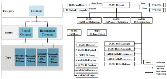
Figure 1.
The organization of information in a three-dimensional database of Revit API (left) and IFC documentation (right).
Ontology is a computer-based knowledge representation method, which allows users to define the concept structure and the relationship between concepts themselves and classify these concepts and relationships through the modeling metalanguage [24]. It not only ensures the compatibility and flexibility of the concept definition but also ensures the formal expression of the concept, making consistency check, knowledge reuse, and knowledge sharing possible [25,26]. Checking IFC from the perspective of ontology framework can make the definition of IFC more formal, consistent, and clear [22]. At present, ontology has been applied to knowledge modeling and rule checking in the field of construction engineering [27], and Protégé is one of the free, open-source ontology editors providing a suite of tools to construct domain models and knowledge-based applications with ontologies [28]. In summary, applying ontology to model transformation can support the following aspects of information interoperability: (1) knowledge sharing; (2) semantic interoperability between computer-based systems and data sources. Thus, this paper takes ontology as an effective method to construct a knowledge system of finite element analysis, such as the reasoning process of the meshing method and element types based on the software Protégé.
3.2. Analysis of IFC Standard
3.2.1. Express-G Model of Component Property and Quantity Information Extraction
After going through the whole IFC4.3 (IFC Version) entities (the classes of information defined by common attributes and constraints as defined in ISO 10303-11) [19], this paper analyzes the logical relationship between entities. The Express-G schema of component property and quantity is shown in Figure 2. The definition of each entity in the diagram can be found in the IFC4 documentation. The IfcPropertySet entity represents the definition of attribute set, and IfcQuantitySet represents the set of measure set. The property set stores all kinds of attribute information of the component, including not only the attribute represented by a single value but also the attribute value of the table and enumeration type. The quantity set stores the basic quantitative information of the component, such as size, area, volume, and so on.
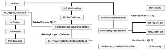
Figure 2.
Express-G expression model of component attributes based on IFC.
3.2.2. Material Information Expression Based on IFC
The Express-G schema of component materials based on IFC is shown in Figure 3. The IFC standard describes component properties and quantity values by defining entities IfcRelDefines associated with IfcObject entities. IfcMaterial represents the material, and ifcRelAssociatesMaterial is associated with the entity IfcElement to realize the expression of component material. The ifcMaterialDefinitionRepresentation entity uses different nodes, curves, and surfaces to represent materials. IfcMaterialDefinition’s HasProperties attribute is associated with IfcPropertySetDefinition to refer to IfcProperty entities that represent properties and then describe material properties.
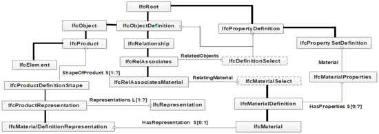
Figure 3.
Express-G expression model of component materials based on IFC.
3.2.3. Information Extraction of Spatial Model Based on IFC
Generally, the IFC standard describes space through the IfcZone entity and IfcSpace entity. The former is an artificially constructed spatial combination. For example, the space involved in a system is composed of several spaces, which can be linked with each other through IfcRelAssignsToGroup entities. The latter is mostly based on the division of construction projects, which is associated with the entities surrounding the space through the associated entity IfcRelSpaceBoundary. In fact, for a room, the predefined attribute set may have common attributes in the verification of outdoor floor height, indoor elevation, and floor net height. When there is no such predefined attribute set, it can be calculated by the coordinates of floor elevation, floor, or wall. For the floor space, the specification is represented by IfcBuilding and IfcBuildingStorey entities and associated with the floor component through the associated entity IfcRelContainedInSpatialStructure. The combination of the construction of spatial concepts can be realized by combining these three spatial concepts with the semantic model constructed based on Figure 2 and Figure 3.
Extracting the element information from IFC files is a necessary process for the automatic modeling of the FEM model. The element information mainly includes the size information of three-dimensional components, the coordinates of key points, lines, and surfaces, and the topological relationship between points, lines, and surfaces. In the IFC standard, the coordinate range of components or space is calculated by georeferencing the world coordinate system with the local coordinate system. Taking wall coordinates for example, the first step is to connect to the global coordinate system through the ObjectPlacement attribute, and the coordinate of the reference point of the example model in the world coordinate system is carried out next. Then, through the connection of the IfcExtrudeAreaSolid or other entities, the coordinates of each control point can be defined by its Depth, Xdim, Ydim, and the definition of the direction of the local coordinate system. The spatial/component coordinate extraction process characterized by the Express-G schema is shown in Figure 4.
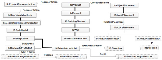
Figure 4.
Method of extracting entity information of spatial model based on IFC.
The material, spatial location, and graphic element information of components are the data basis of BIM-FEM conversion. In this paper, we add model attributes based on the object model diagram constructed above. The development engines such as Xbim [29] (allows .NET developers to read, create, and view building information models in the IFC format) and ifcjavatoolbox [30] (a Java framework for accessing and visualizing IFC-based building information models) could be used to design the association class library based on the IFC standard. Through programming, the entities and attribute relations shown in Figure 2, Figure 3 and Figure 4 can be adopted to quickly locate, extract, and edit various attributes, and the finite element command stream can be generated based on the extracted information.
3.3. Automatic Decision Making of Element Type Based on BIM and Ontology
The decision making of element type and meshing method needs to give consideration to the information of component type, size, and function, and this study focusing on element type designs a complete technical route for automatic selection.
On the one hand, the establishment of an element-type decision-making system is the basis of element automatic selection, and the selection of element type usually needs to be combined with the characteristics of components. Overall, according to the geometric characteristics, the finite elements can be divided into three categories: skeletal structure, plate/shell structure, and solid structure, as shown in Table 5. These three types of structures can be further subdivided according to their functions and geometric characteristics of components. For example, in the skeletal structure, when the member 15 > L/h ≥ 4, the beam element considering shear deformation should be adopted. The Link8 element (a bar element that can be applied to various engineering practices), which only withstands the axial tension and compression of the bar, does not withstand the bending moment, and the nodes only have translational degrees of freedom, so it can be used to model trusses, sagging cables, links, springs, etc. Therefore, the component type, parameter characteristics, material information, function, or other information can be transformed into the fields of ontology such as class, object properties, and data properties, and the ontology rule can be constructed according to the threshold set by the element judgment rule.
Table 5.
Characteristics and three types of structures.
On the other hand, the conversion from BIM to ontology data is often implemented by the IfctoRDF tool [31], which can convert BIM files in IFC format to ttl format (a format that can be imported into ontology software) and combine them with the ontology knowledge base. Specifically, taking REVIT software and Protégé software as examples, IFC files are first extracted from REVIT software and then converted into ontology format by the IfctoRDF tool, which can be displayed by ontology software such as Protégé and combined with the knowledge base. In the conversion process of BIM data, to use the classes, attributes, and rules specified in the ontology knowledge base for a compliance review, it is necessary to set the association among fields, such as setting the equivalence between the ‘column’ class and ‘IfcColumn’ class. The instance classified as IfcColumn in BIM can be used as the column class, and the element type is selected according to the component properties and usage based on the constructed ontology reasoning system.
Similarly, important model parameters such as the parameters required for meshing and the nodes and lines required for finite element modeling can also be obtained in this way. For the information such as element type obtained by reasoning, it can be extracted by programming based on documents such as Jena (i.e., a free and open-source Java framework for building semantic web and linked data applications) or OWL API (Web Ontology Language API). In summary, the whole process framework including the formation of element selection ontology construction ideas, class examples, model data conversion, reasoning, and extraction is shown in Figure 5.

Figure 5.
Framework of construction idea of the element type, data conversion, inference, and extraction based on BIM and ontology.
3.4. Geometric Modeling and Command Stream Generation
The extraction of point–line–surface entity information mentioned above may reduce the dimension of components in the process of BIM-FEM conversion. Structures such as beams, columns, and trusses are usually represented as two-dimensional elements in the finite element method. Avoiding the impact of component dimension reduction, this paper first extracts important information such as cross-section shape and moment of inertia, then judges the bar element and its neglected dimension based on BIM and ontology and records the important node coordinates of the remaining two dimensions and the connection mode between nodes. The process schematic of recording information on rod elements is shown in Figure 6.
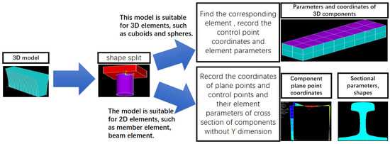
Figure 6.
The process schematic of recording information of rod elements.
The realization of automatic finite element modeling requires the combination of graphic element information, material information, element type, meshing parameters, and other information into command stream files identified by finite element software. The specific process includes finding out the command, extracting relevant information according to the meaning of the parameter, and filling the extracted information in the corresponding position of the parameter. For example, the automatic generation process of setting commands KATT, MAT, REAL, TYPE, and ESYS (using ANSYS parametric programming language) for a node unit is shown below:
- KATT commands are obtained according to the characteristics of the node.
- Material values are obtained according to the model material of the node, and the corresponding material number of the component is obtained from the definition statement of the material.
- The real constant number, the element type number, and the coordinate system number are obtained in similar ways.
- One to three are filled into the corresponding position by programming statements.
3.5. Case Study
A simple frame construction model case study was performed to validate the research route, extension methods, and technical means, as shown in Figure 7. Tools including Revit, Xbim, IfctoRDF, Protégé5.5, JAVA, Jena and ANSYS are involved in this case. Firstly, the analysis rules were extracted, and the corresponding ontology reasoning knowledge system was established according to the finite element analysis theory of ANSYS software. Secondly, IFC files were expanded according to structural analysis requirements and then combined with the ontology database in the appropriate format. The information of boundary constraints was manually added to the ontology in this case, and it can actually be set properties through the IFC extension. In future work, we will use IFC schema to automatically extract. Then, the classes and attributes specified in the ontology knowledge base were used to correlate the fields. Finally, with the help of the JAVA platform, the Jena package was imported for reasoning, and the information required by ANSYS was obtained so that the finite element analysis of the corresponding BIM structural model can be carried out in ANSYS.
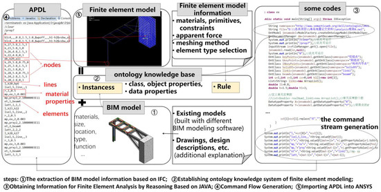
Figure 7.
Case study.
With the purpose of validating the converting results based on ontology, comparative tests of the result were created with the method of intermediate file format ACIS (can direct export from Revit, can be directly imported ANSYS), as shown in Figure 8. This comparative result shows that the method of the finite element model based on BIM and ontology is substantially better than direct file transfer.
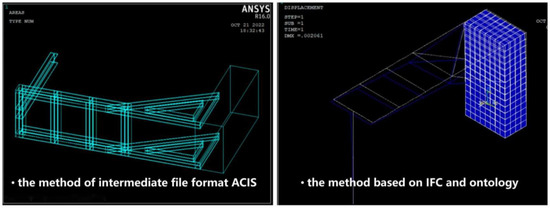
Figure 8.
Comparative result.
4. BIM-FEM Conversion Process and Software Architecture Design
For the further overall software architecture design, the BIM-FEM holistic conversion process was designed in detail, as shown in Figure 9. Firstly, the traversal graphic elements are utilized to obtain the boundary point of the current graphic element in the BIM instance. The element type is judged by the combination of element size, material parameters and other parameters. Secondly, the effective range of boundary points and material information is extracted according to the selection of component graphic element, constraint graphic element, force element type, and structural grid division mode. Thirdly, the point–line–surface entity is generated by the model connection method according to the extracted boundary points. Finally, the point–line–surface entity and integrated material information are matched to form a command stream.
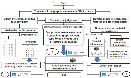
Figure 9.
BIM-FEM model transformation process and method.
BIM-FEM software architecture is designed based on BIM data such as the REVIT model. Firstly, for the data acquisition, components information is extracted through IFC analysis and BIM data format conversion to implement interoperability. Secondly, for the database design, material type, material parameters, or other conventional information management take a common database approach. Element selection, meshing, and other reasoning processes using ontology knowledge base reasoning and storage. Thirdly, for the command stream generation, the arrangement of parameters in a single command stream and the combination of multiple command streams are mainly carried out by programming. The final BIM-FEM software architecture design is shown in Figure 10.
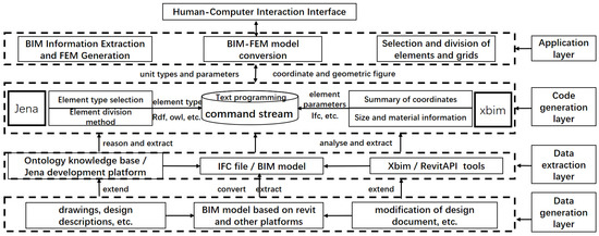
Figure 10.
Software architecture Design of BIM-FEM.
5. Conclusions
This paper discussed the finite element model generation method based on BIM and ontology. Ontology transforms the manual method of element type and meshing in finite element analysis into a knowledge reasoning mechanism, so structural designers can improve design efficiency. The extraction of geometry, spatial relationships, quantities, and properties in BIM were extracted by IFC expansion, enabling multi-source heterogeneous data to be integrated with minimum effort. In addition, this paper considered the impact of component dimension reduction in the process of extracting information and put forward the corresponding solutions. All the potential applications were implemented as a proof of concept and applied to simple frame structure models to ensure their practicality. Finally, the BIM-FEM transformation software architecture design was accomplished, which is scientific, practical, and complete, and is fundamental for further software development.
This research also has several deficiencies and limitations. Firstly, this paper discussed the automatic conversion of the BIM-FEM from the aspects of theory, method, technology, and process, and does not further implement software development. Secondly, when combining BIM with ontology for feature reasoning, manual work about construction rules is still inevitable. The NLP (Natural Language Processing) method could also be embedded to explore the automatic generation algorithm of reasoning rules and improve the conversion efficiency of BIM-FEM in the future. Finally, the current IFC standard still has limitations in the expression of finite element concepts, and the expansion mechanism of IFC will be further explored combined with the finite element semantics.
Author Contributions
Conceptualization, J.J., J.G. and W.W.; methodology, W.W., L.M. and Z.Z.; software, J.G. and W.W.; resources, J.J., L.M. and J.L.; writing—original draft preparation, J.G. and W.W.; writing—review and editing, J.J., J.G. and Z.Z.; project administration, J.J.; funding acquisition, J.J. All authors have read and agreed to the published version of the manuscript.
Funding
This research was funded by the National Natural Science Foundation of China (Grant No. 51908523) and the China Scholarship Council (File No. 201906335029).
Data Availability Statement
Not applicable.
Conflicts of Interest
The authors declare no conflict of interest.
References
- Azhar, S. Building Information Modeling (BIM): Trends, Benefits, Risks, and Challenges for the AEC Industry. Leadersh. Manag. Eng. 2011, 11, 241–252. [Google Scholar] [CrossRef]
- Lai, H.H.; Deng, X.Y. Interoperability Analysis of Ifc-Based Data Exchange between Heterogeneous Bim Software. J. Civ. Eng. Manag. 2018, 24, 537–555. [Google Scholar] [CrossRef]
- ANSYS. Available online: https://www.ansys.com (accessed on 22 October 2022).
- Abaqus. Available online: https://www.3ds.com/products-services/simulia/products/abaqus/ (accessed on 22 October 2022).
- Adina. Available online: https://www.adina.com/ (accessed on 22 October 2022).
- Klinc, R.; Gabršček, D.; Česnik, J.; Žibert, M.; Hostnik, M.; Logar, J. Development of a Semiautomatic Parametric Method for Creation of an I-BIM Model of a Tunnel for Use in FEM Software. J. Adv. Transp. 2021, 2021, 8843277. [Google Scholar] [CrossRef]
- Volk, R.; Stengel, J.; Schultmann, F. Building Information Modeling (BIM) for Existing Buildings-Literature Review and Future Needs. Autom. Constr. 2014, 38, 109–127. [Google Scholar] [CrossRef]
- Xiao, L.; Liu, Y.; Du, Z.; Yang, Z.; Xu, K. Model Analysis and Optimization of Bim Technology in High-Rise Shear Wall Residential Structure. MATEC Web Conf. 2019, 3, 1–5. [Google Scholar] [CrossRef]
- Zhou, H.; He, X.; Leng, X.L. Development and Application of a Revit-ANSYS Model Transformation Interface. In IOP Conference Series: Earth and Environmental Science, Proceedings of the 11th Conference of Asian Rock Mechanics Society, Beijing, China, 21–25 October 2021; IOPscience: Bristol, UK, 2021; Volume 861, pp. 1–8. [Google Scholar]
- Jeong, Y.-S.; Eastman, C.; Sacks, R.; Kaner, I. Benchmark Tests for Bim Data Exchanges of Precast Concrete. Automat. Constr. 2009, 18, 469–484. [Google Scholar] [CrossRef]
- Habte, B.; Guyo, E. Application of Bim for Structural Engineering: A Case Study Using Revit and Customary Structural Analysis and Design Software. J. Inf. Technol. Constr. 2021, 26, 1009–1022. [Google Scholar] [CrossRef]
- Liu, Z.Q.; Li, Y.G.; Zhang, H.Y. Ifc-Based Integration Tool for Supporting Information Exchange from Architectural Model to Structural Model. J. Central South Univ. Technol. 2010, 17, 1344–1350. [Google Scholar] [CrossRef]
- Xu, Z.; Rao, Z.; Gan, V.J.L.; Ding, Y.; Wan, C.; Liu, X. Developing an Extended Ifc Data Schema and Mesh Generation Framework for Finite Element Modeling. Adv. Civ. Eng. Mater. 2019, 2019, 1434093. [Google Scholar] [CrossRef]
- Park, S.I.; Lee, S.-H.; Almasi, A.; Song, J.-H. Extended Ifc-Based Strong Form Meshfree Collocation Analysis of a Bridge Structure. Autom. Constr. 2020, 119, 1–21. [Google Scholar] [CrossRef]
- Zou, D.; Chen, K.; Kong, X.; Yu, X. An Approach Integrating Bim, Octree and Fem-Sbfem for Highly Efficient Modeling and Seismic Damage Analysis of Building Structures. Eng. Anal. Bound. Elem. 2019, 104, 332–346. [Google Scholar] [CrossRef]
- Alsahly, D.A.; Hegemann, D.F.; König, D.M.; Meschke, T.G. Integrated Bim-to-Fem Approach in Mechanised Tunnelling. Geomech. Tunn. 2020, 13, 212–220. [Google Scholar] [CrossRef]
- Khan, M. Integrating BIM with ERP Systems Towards an Integrated Multiuser Interactive Database: Reverse-BIM Approach. In Recent Trends in Construction Technology and Management. Lecture Notes in Civil Engineering; Ranadive, M.S., Das, B.B., Mehta, Y.A., Gupta, R., Eds.; Springer: Singapore, 2022; Volume 260, pp. 209–220. ISBN 978-981-19-2145-2_17. [Google Scholar]
- Swanson, J.A.; Cameron, G.R.; Haberland, J.C. Adapting the Ansys Finite-Element Analysis Program to an Attached Processor. Computer 1983, 16, 85–91. [Google Scholar] [CrossRef]
- IFC4 Documentation. Available online: https://standards.buildingsmart.org/IFC/RELEASE/IFC4/ADD2_TC1/HTML/ (accessed on 22 October 2022).
- Oneline Documatation for the Revit API. Available online: https://www.revitapidocs.com/ (accessed on 22 October 2022).
- Venugopal, M.; Eastman, C.M.; Sacks, R.; Teizer, J. Semantics of Model Views for Information Exchanges Using the Industry Foundation Class Schema. Adv. Eng. Inform. 2012, 26, 411–428. [Google Scholar] [CrossRef]
- Jiang, S.; Jiang, L.; Han, Y.; Wu, Z.; Wang, N. OpenBIM: An Enabling Solution for Information Interoperability. Appl. Sci. 2019, 9, 5358. [Google Scholar] [CrossRef]
- buildingSMART. Available online: https://technical.buildingsmart.org/ (accessed on 22 October 2022).
- Sinha, P.K.; Gajbe, S.B.; Debnath, S.; Sahoo, S.; Chakraborty, K.; Mahato, S.S. A Review of Data Mining Ontologies. Data Technol. Appl. 2021, 56, 172–204. [Google Scholar] [CrossRef]
- Studer, R.; Benjamins, V.R.; Fensel, D. Knowledge Engineering: Principles and Methods. Data Knowl. Eng. 1998, 25, 161–197. [Google Scholar] [CrossRef]
- Rasmussen, M.H.; Lefrançois, M.; Schneider, G.F.; Pauwels, P. Bot: The Building Topology Ontology of the W3c Linked Building Data Group. Semant. Web 2021, 12, 143–161. [Google Scholar] [CrossRef]
- Mohammadi, S.; Tavakolan, M.; Zahraie, B. An Intelligent Simulation-Based Framework for Automated Planning of Concrete Construction Works. Eng. Constr. Arch. Manag. 2022, 29, 916–939. [Google Scholar] [CrossRef]
- Gennari, J.H.; Musen, M.A.; Fergerson, R.W.; Grosso, W.E.; Crubézy, M.; Eriksson, H.; Noy, N.F.; Tu, S.W. The Evolution of Protégé: An Environment for Knowledge-Based Systems Development. Int. J. Hum.-Comput. Stud. 2003, 58, 89–123. [Google Scholar] [CrossRef]
- XBIM. Available online: https://docs.xbim.net/index.html (accessed on 22 October 2022).
- apstex IFC Framework. Available online: http://www.apstex.com/info.html (accessed on 22 October 2022).
- Ifctordf. Available online: https://github.com/pipauwel/IFCtoRDF (accessed on 22 October 2022).


Publisher’s Note: MDPI stays neutral with regard to jurisdictional claims in published maps and institutional affiliations. |
© 2022 by the authors. Licensee MDPI, Basel, Switzerland. This article is an open access article distributed under the terms and conditions of the Creative Commons Attribution (CC BY) license (https://creativecommons.org/licenses/by/4.0/).