Article

Feasibility Evaluation of Novel High-Damping Rubbers as Energy-Dissipation Material under Axial Dynamic Load for Damper Devices

Department of Civil Engineering, Faculty of Engineering, Universiti Malaya, Kuala Lumpur 50603, Malaysia
*
Author to whom correspondence should be addressed.
Buildings 2022, 12(11), 1917; https://doi.org/10.3390/buildings12111917
Submission received: 25 September 2022 / Revised: 26 October 2022 / Accepted: 3 November 2022 / Published: 7 November 2022
(This article belongs to the Special Issue Improvement Technology on Building Seismic Toughness)

Abstract

:
High-damping rubber (HDR) material has been widely used in bearings for seismic-isolation devices in structures. Nevertheless, HDR has not yet been developed in dampers to reduce the response of structures to earthquake excitations by dissipating the energy applied to the structures under direct axial load. The purpose of this paper was to evaluate the feasibility of using novel hyperelastic composite material (HECM), which is an HDR material, in experimental investigations to determine its damping ratio, compressibility, and elasticity behavior under axial dynamic load for the development of novel dampers in the future. First, a series of tests on HECM was conducted using the double-shear method to determine the most suitable sample for a purely dynamic compression test. Subsequently, the HECM was used in a device working as a scaled-down damper under both direct tension and compression dynamic load conditions, and pure direct compression dynamic load conditions were tested. Various thicknesses of the HECM (6, 8, and 10 mm) used in the testing damper were examined under a constant force with various frequencies of 0.01, 0.1, 0.25, and 0.5 Hz. The results show that the 10 mm thick HECM can provide a high damping ratio of 10% to 13% under axial conditions. Hence, this study is important for evaluating HECM, which has the potential for use in developing a full-scaled rubber damper system to resist axial force in the future. The damper is a novel rubber damper with high damping capability to dissipate energy under axial load. Furthermore, the damper can serve as an alternative choice that is more durable and overcomes the current weaknesses of passive dampers.

1. Introduction

High-damping rubber (HDR) is a passive vibration-control material used in seismic-isolation or base-isolation systems. The common types of base isolators that utilize HDR are high-damping natural rubber bearing (HDRB) and lead rubber bearing (LRB) [1]. HDRB is an elastomeric bearing that consists of thin layers of high-damping rubber and steel plates with an alternate layer. The low shear modulus of the elastomer controls the horizontal stiffness of the bearings, whereas steel plates provide high vertical stiffness and prevent the bulging of the rubber [2]. HDR can also enhance the seismic resilience of structures such as school buildings and tunnel-lining structures by acting as isolators in structural frames or in the joints between structures [3,4] and will be a new approach to consider in seismic resilience. HDRB provides a horizontal damping ratio of 10–20% [5,6] and can be improved by incorporating additional fine carbon blocks, resins, oils, and proprietary fillers. Natural rubber facilitates flexibility through its ability to move and return to its normal position [2,7]. According to our literature review, HDR is mainly used in bearing or base isolation that uses the lateral behavior of HDR in shear [8] but not in the axial force behavior of HDR. The restoring force characteristics, the effect of loading frequency, and the effect of large displacement are among the important properties that need to be designed, and it was stated that the restoring force characteristics of HDR are similar to those of a linear viscous damper [9]. Restoring forces are expressed by stiffness K and linear damping coefficient C. The dynamic properties and strength of HDR show the possibility of the benefits of seismic dampers because (1) they permit energy dissipation, even for small horizontal deformations or micro-vibrations [10]; (2) there is a lower permanent deformation after seismic activities; and (3) the increase in temperature is small, which does not affect the dynamic performance. Typically, HDR can function well from −30 °C to +50 °C [11,12], and the damping ratio seems to be not correlated with temperature [13].
Dampers currently available in the industry can be utilized according to structural requirements, such as friction dampers, metallic dampers, buckling restrained braces, tuned liquid/mass dampers, and viscoelastic and viscous-fluid dampers [14,15]. Dampers work under direct axial conditions; viscous-fluid velocity-dependent devices in the form of cylinder type and viscoelastic (VE) dampers are popularly used for energy dissipation under seismic and wind-induced dynamics due to their excellent performance and reduction effect on the relative displacement of structures [16,17]. However, when the end of the damper moves with respect to the others, viscoelastic materials or fluids undergo shearing behavior. The heat produced from the shearing action dissipates energy. The mechanical or dynamic properties that require attention are the response of the storage modulus, loss modulus, damping coefficient, and loss factor to the frequency of motion, strain amplitude, and temperature [18]. As the number of cycles increases, the increase in temperature reduces the storage and loss moduli, resulting in a reduction in stiffness and energy dissipation capacity [19,20,21,22]. The performance of the viscous fluid is significantly reduced once the liquid leaks [23], which leads to frequent maintenance of the damper, thereby increasing the overall life cost in the design life period of the structure. Viscous-fluid dampers can operate at ambient temperatures ranging from −40 °C to 70 °C, but variations in temperature in the range of 0 °C to 50 °C result in variations in the damping ratio of +44% to −25% [21]. However, other dampers, such as displacement-dependent devices, do not carry vertical loads [24,25], and their behavior mainly depends on displacement rather than velocity. Both devices are well-defined in EN 15129 [26]. Viscous dampers generally provide a range of damping ratios of 10% to 30% [27], with an average of approximately 15%. In other words, if any device achieves more than a 10% damping ratio, it has a function similar to that of a viscous damper when using a direct axial under a dynamic load.
Hence, HECM will overcome all the weaknesses of the dampers above if it is successfully used. The proposed HECM was designed using displacement-dependent behavior under a vertical load similar to that of a velocity device. EN 15129 does not cover the direct testing requirements of HECM under axial force; hence, the testing procedures in this study referred to the fundamental testing requirements specified in EN 15129 under a high-damping elastomer with modification using direct axial load. Once the novel hyperelastic composite material is developed, a novel type of damper can be developed in the future to best fit it due to its advantages over other dampers, as described above. The successful development of this HECM, on the other hand, will create the opportunity for a replacement material for those currently used in passive dampers, such as friction dampers, viscoelastic dampers, and metallic dampers, and will potentially have an edge due to the HECM providing higher damping, being durable in nature, and exhibiting good performance under shearing.

2. Material Testing Method

2.1. Hyperelastic Composite Material

The damping testing of the material for the HECM was conducted before the axial dynamic loading. Dynamic tests were conducted to determine the damping ratio according to Clause 8.2.4.2.5 in EN 15129:2009. Although the actual behavior of the HECM in the product is directly under an axial load, the testing of the HECM under Clause 8.2.4.2.5 in EN 15129:2009 is the direct shear method. There is no provision under EN 15129 for material testing directly under axial load for elastomer materials. Hence, the materials were tested using the provision in EN 15129. The test method in accordance with EN 15129 is straightforward and determines which HECM composition has the highest damping ratio under shear, which has a direct correlation in the axial direction. Finally, the most suitable HECM was chosen after a number of different samples were obtained.

2.2. Test Procedures

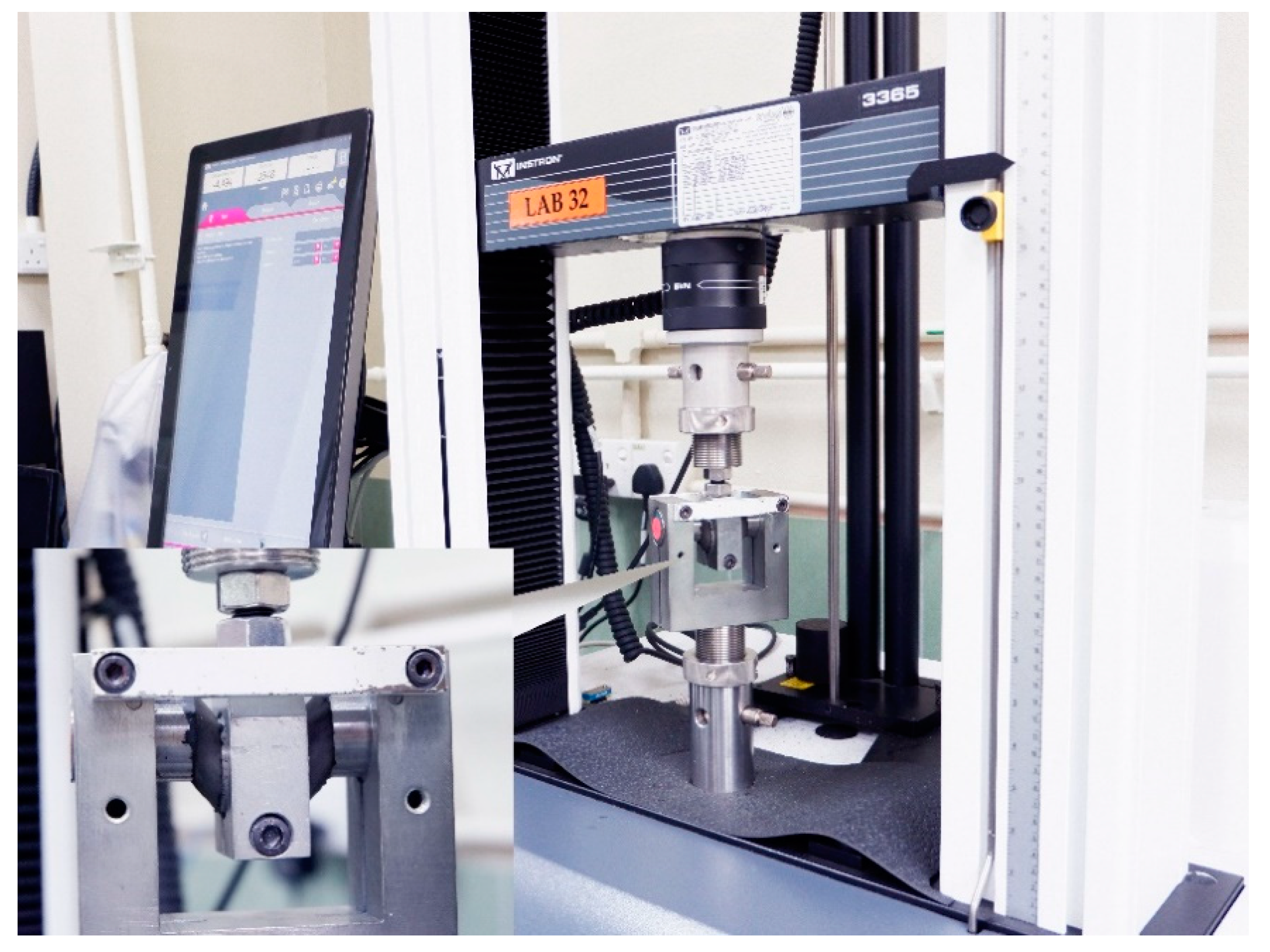
The double-shear test piece was used to characterize the HECM during material development, particularly to determine the mechanical properties of the material. Under normal circumstances, a double-shear test piece was used to determine the damping property of the elastomer. The configuration and dimensions of the double-shear test piece are illustrated in Figure 1. Dynamic tests were performed using an INSTRON servo-hydraulic testing machine, as shown in Figure 2. The load cell capacity of the testing machine was 25 kN with a stroke displacement of ±75 mm.
A wave matrix module integrated with an INSTRON servo-hydraulic testing machine was used to program the dynamic tests. All the double-shear test pieces were dynamically tested by varying the strain amplitudes from 5% to 10%, 20%, 50%, 70%, 100%, and 150% at a frequency of 0.5 Hz. These testing conditions were applied according to EN15129:2009 clause 8.2.2.1.3.2: effect of the strain amplitude. Five consecutive cycles were programmed for each strain amplitude to record the force and displacement data. The tests were performed in ascending order of the strain amplitude. The dynamic horizontal force–displacement data were analyzed cycle by cycle using Equation (1), as stated in BS EN 15129:2009 Annex G.5. The method of analysis expresses stiffness as
K b = F + F d + d
where F and d are the horizontal force and the displacement, respectively. d+ and d are the maximum and minimum displacement values in the cycle, respectively, and F+ and F are the force values at those displacements.
The dynamic test measures the damping or hysteresis energy loss within an elastomer subjected to cyclic deformation. The damping ratio ξ was calculated using Equation (2), as stated in EN15129 Annex G.5. The equivalent viscous damping ratio ξ is expressed as follows:
ξ = 2 H π K b   d + d 2
where H is the area of the hysteretic loop, and Kb is the effective stiffness.
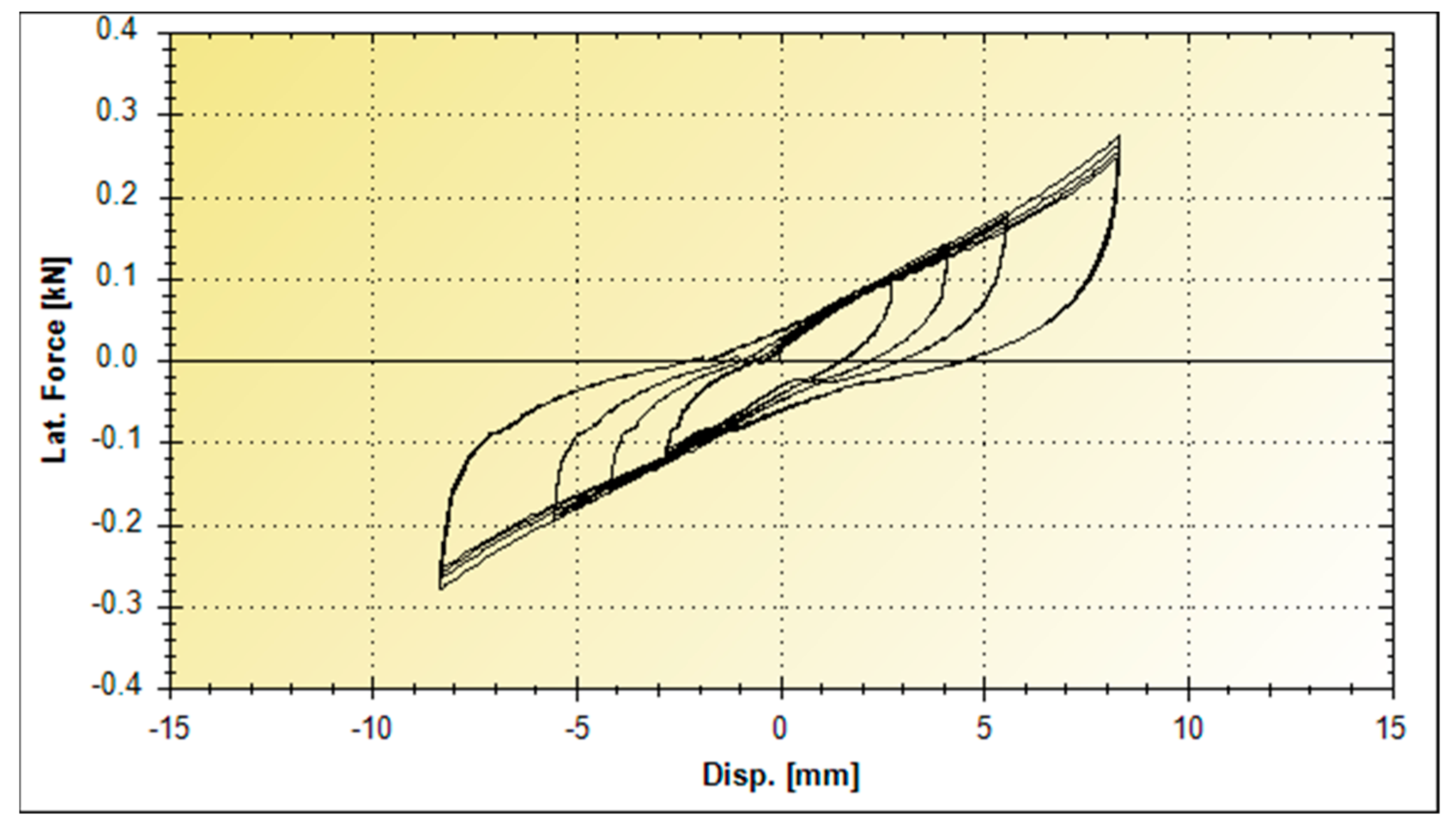
All the force and displacement data were used to calculate the damping ratio. The calculations were executed using the data generated by the INSTRON machine and plotted in the Excel graph shown in Figure 3. The results of the damping ratio according to the BS EN 15129:2009 document for rubber samples are listed in Table 1. G is the shear modulus of rubber. According to BS EN 15129:2009, the damping ratio is the third loading cycle of 15.25%. This HECM was chosen because it had the highest damping ratio among others and, therefore, was used as a sample in the dynamic axial load model.

3. Development of Hyperelastic Composite Material under Dynamic Axial Loads

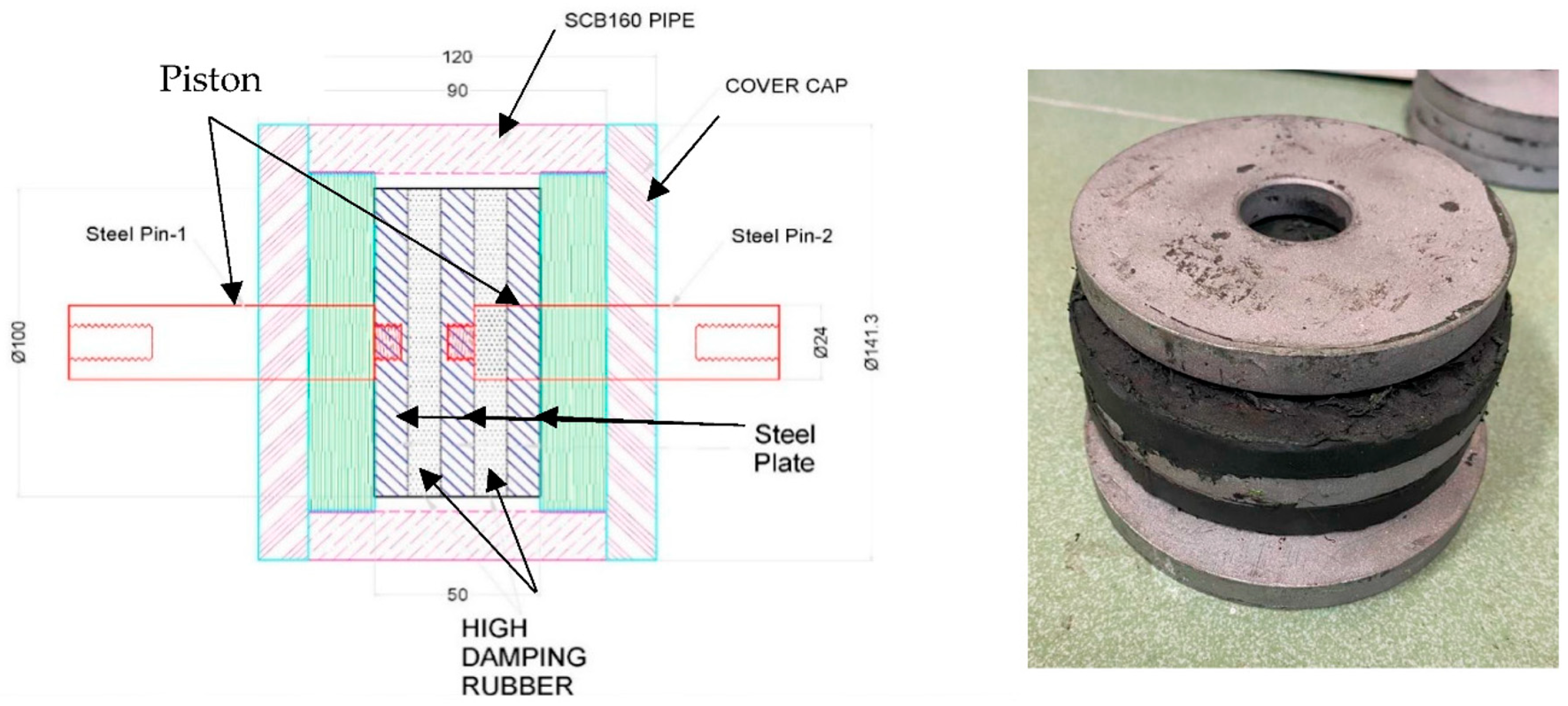
The above HECM was placed in a scaled-down damper, which was subjected to a direct axial load. Figure 4 shows the isometric view and dimensions of the proposed hyperelastic composite material used for testing. It consists of two discrete pistons mounted on a steel plate, which act in compression alternately with each high-damping rubber when axial pushing and pulling forces are exerted. The pushing and pulling movements simulate the rotation in the beam–column joint of the structural framing under dynamic loading. The HECM has energy-dissipation capability to reduce the amplitude, velocity, and acceleration of vibration with minimal reaction force. This mechanism is contained within a cylindrical steel tube casing, which confines the boundary condition of the mechanical system.
The steel parts are all corrosion-protected according to international standards, depending on the location, environmental conditions, and required degree of protection. Upon request, a special arrangement can cater to the wider needs of the environmental conditions. The rubber thickness was controlled by the allowable design pressure stated in EN 1337-3 [28]. For this sample test, a maximum thickness of 10 mm was used. There were three types of samples with thicknesses of 6 mm, 8 mm, and 10 mm. According to EN 15129 clause 8.2.4.1.5.2, the cyclic frequency should be 0.5 Hz and at least 0.01 Hz for a bearing isolator in a shear damping test since there is no provision for testing under compression conditions. Thus, these frequency values were used as a basis for testing. The interval frequencies 0.1 Hz and 0.25 Hz were used to obtain the damping behavior and correlation between 0.01 Hz and 0.5 Hz. Thus, each type of sample was tested at different frequencies of 0.01 Hz, 0.1 Hz, 0.25 Hz, and 0.5 Hz. The test plan is described in subsequent sections. The effects of the rubber thickness and loading frequency on the device’s damping ratio value were investigated.

4. HECM under Dynamic Axial Loads

4.1. Test

The testing of the proposed HECM was conducted, and the HECM was tested using the double-shear method as per the BS EN 15129 requirements described in Section 2. The actual product, however, was tested using the axial compression load method. The HECM damping behavior in the axial direction was expected to be lower than in the shear direction. During the dynamic cyclic loading test, both rubber layers alternately experienced tension and compression. Generally, high-damping rubber has a better performance in compression conditions, but the HECM performance is reduced under tension. As a result, two samples of dampers with 10 mm thick HECM were produced to test the testing mechanism. The first sample was designed to ensure that the two rubber layers experienced tension and compression alternately during the dynamic cyclic loading test. The second sample was designed to ensure that the rubbers were only subjected to pure compression for both layers. The force, F applied in Equation (1), is the axial force.

4.2. Testing on the Device Sample with Tension–Compression Behavior

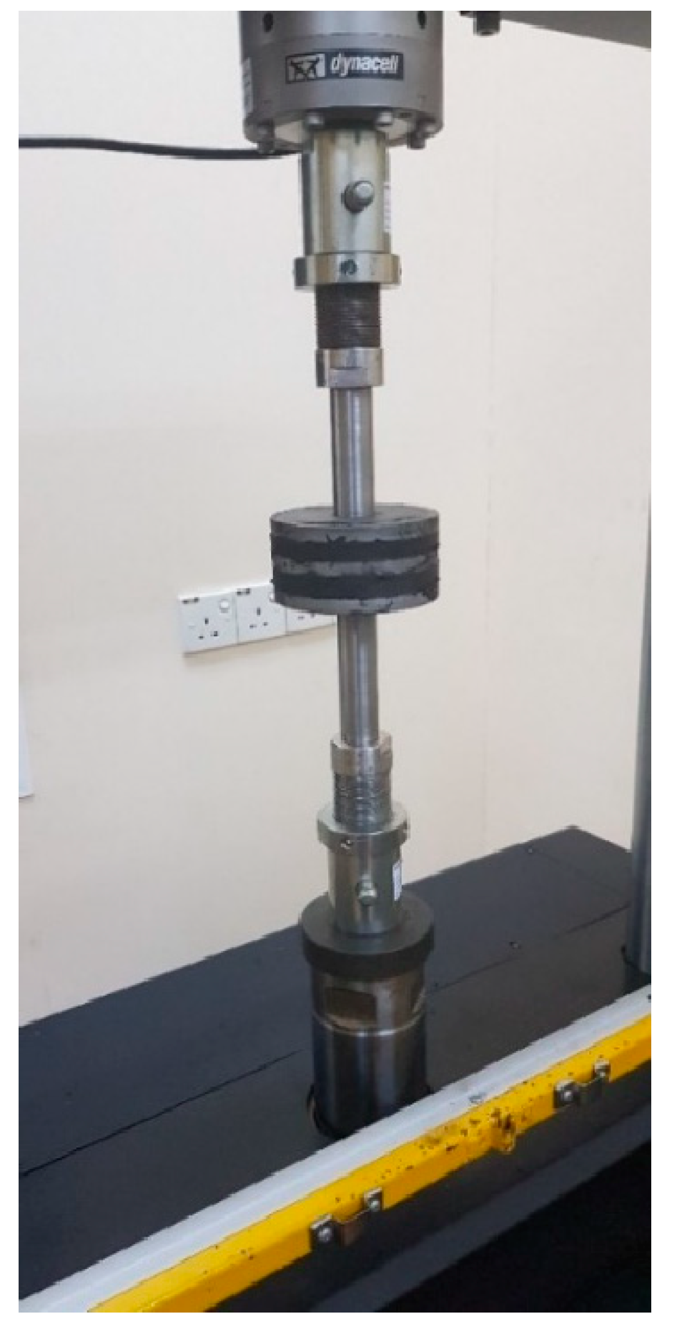
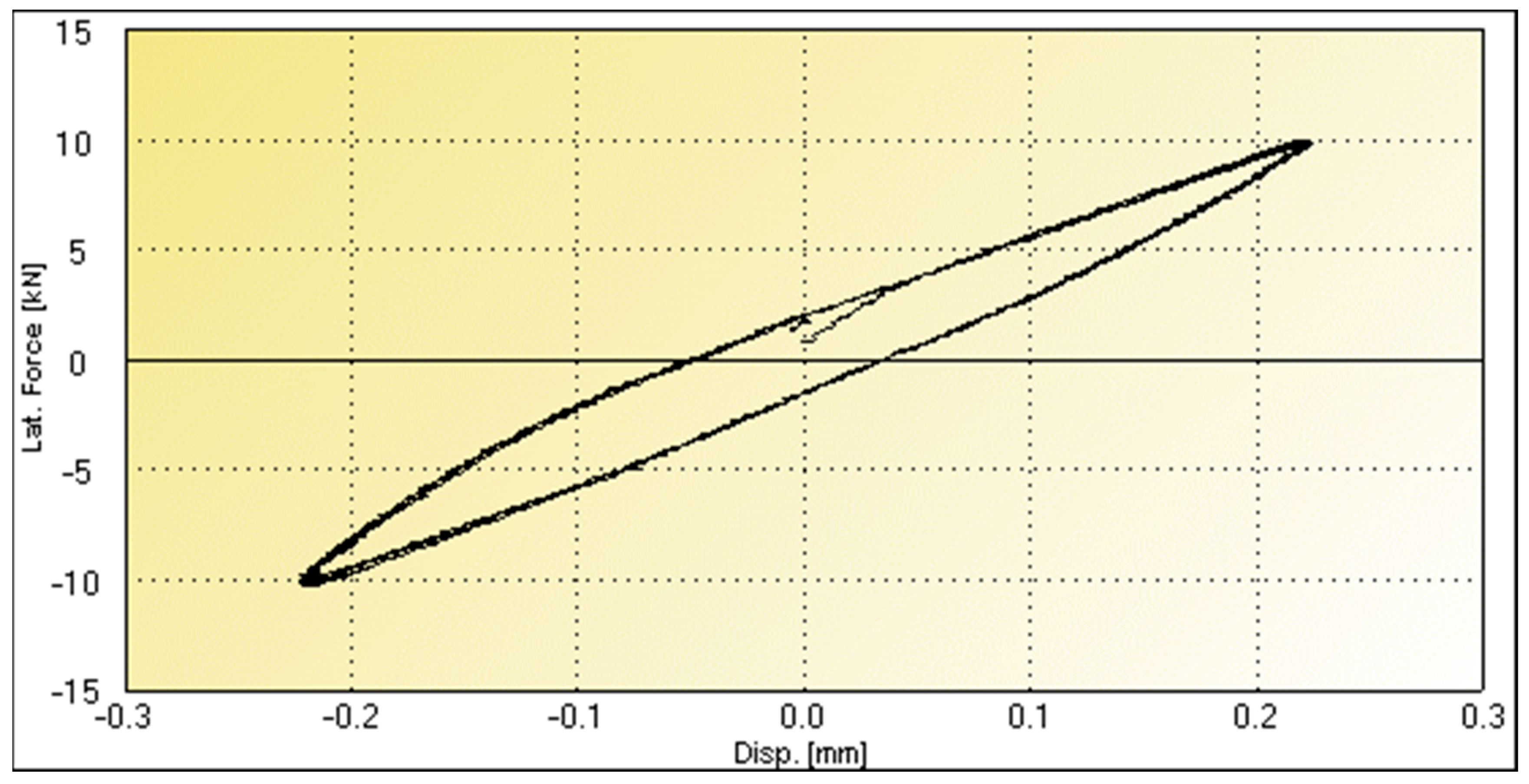
Testing was performed using a Dynacell machine, as shown in Figure 5. The sample was fixed at the soffit, and the top piston induced a 10 kN compression and tension force at a cyclic frequency of 0.01 Hz. When the tension force was applied, the steel plate at the center, which was mounted on the top piston, exerted a compression force on the top-layer rubber, while the bottom layer was in tension. Similarly, when a compression force was applied, the steel plate exerted a compression force on the bottom rubber layer, while the top layer was in tension. Table 2 and Figure 6 show the data and force–displacement graph for the first sample, respectively. The results showed that the sample produced a symmetrical hysteretic loop graph with a damping ratio of 8.48% using Equation (2), as shown in Table 2 and Figure 6. This is almost half the value obtained using the shear method. This indicates that the damping ratio of the damper may be significantly reduced by the tension behavior. The reduction factor due to the tension condition can be verified by comparing the results under purely compression conditions. Hence, it is vital to ensure that the rubber is under compression. If the tension behavior reduced the damping, then to produce maximum damping under natural behavior, the second sample purely under compression was proposed to test the subsequent performance.

4.3. Testing of the Device Sample with Pure Compression Behavior

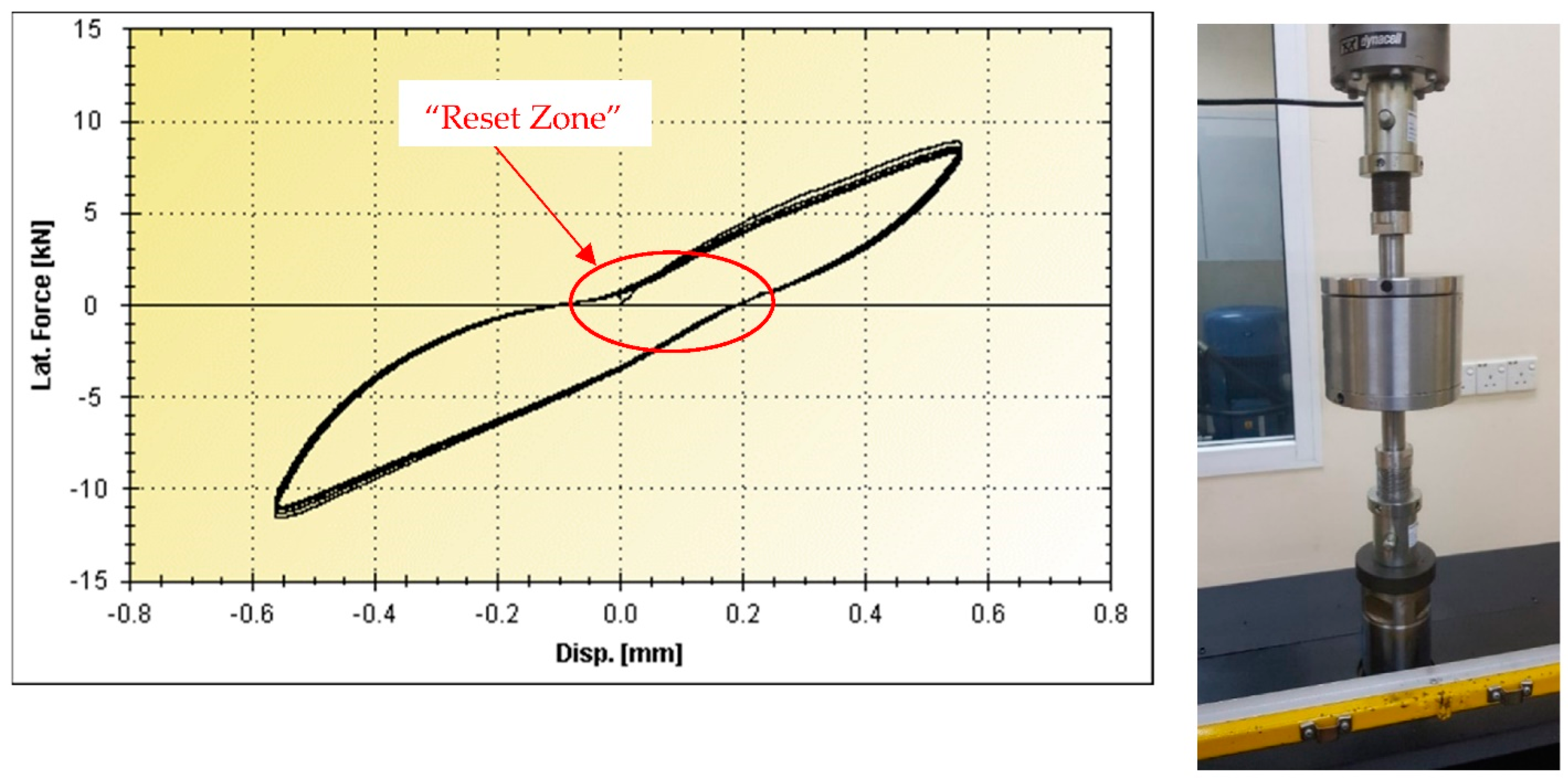
To examine the rubber behavior under pure compression, the product sample was modified with no adhesive applied at the surface of the center steel plate, as shown in Figure 4. The sample was enclosed to confine the rubber during the cyclic loading. This is similar to the smaller scale of an actual damper. According to the results presented in Table 3 and Figure 7, the profile shape of the hysteretic graph is similar to that shown in Figure 6, except for the portion where the force was close to zero. This result illustrates the actual condition of the product, where the piston was released from one side of the rubber before engaging the opposite side of the rubber. There was a very short period during which the piston was in the reset zone. This is represented in the graph by the fact that the line does not continue straight and instantly drops when near zero force before it increases in force again, as highlighted in the graph. This slightly reduced the damping of the product. Nevertheless, the sample under pure compression exhibited a 13.7% damping ratio using Equation 2 under the third cycle, as shown in Figure 7. This shows that the damping ratio increased by more than 50%, compared with the previous test. As the result under pure compression produced better results, in subsequent testing, we used a sample under compression for different thicknesses of high-damping rubber and frequencies.

4.4. The Effects of Rubber Thickness and Load Frequency under Pure Compression

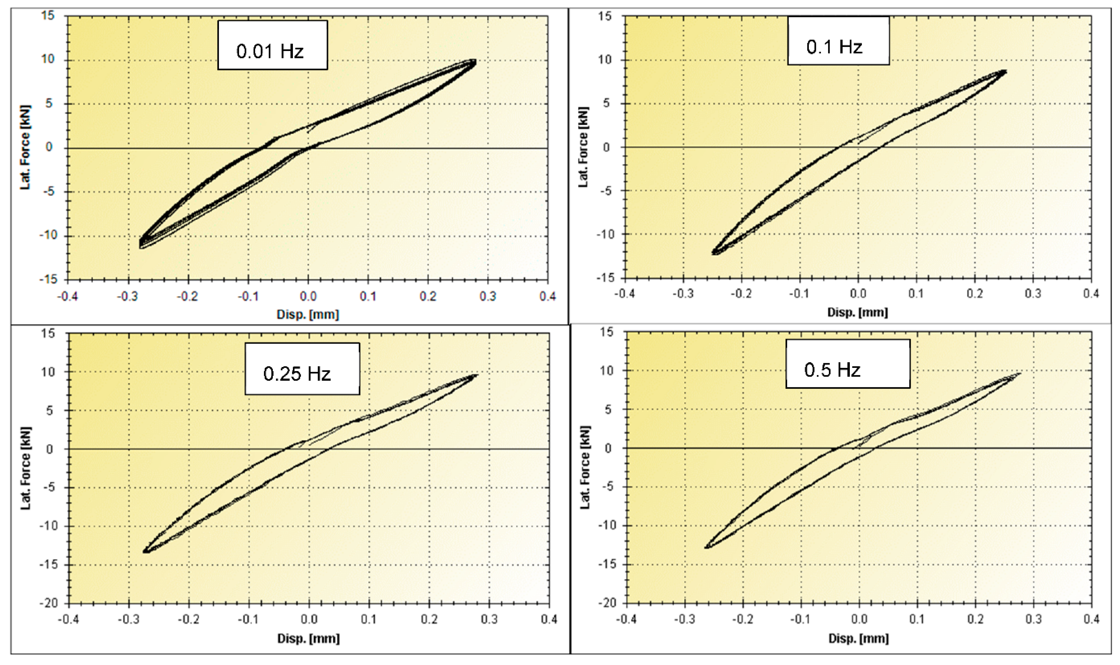
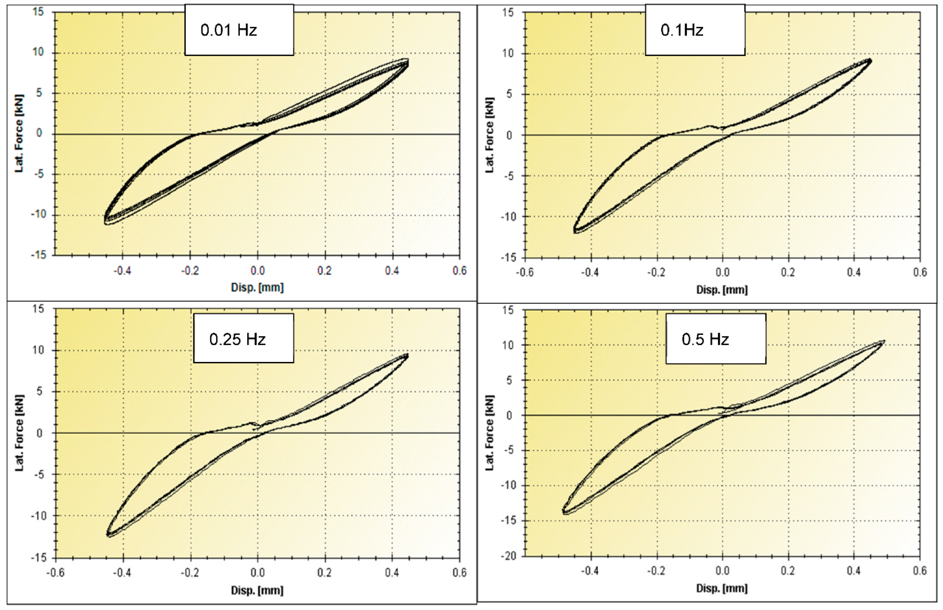
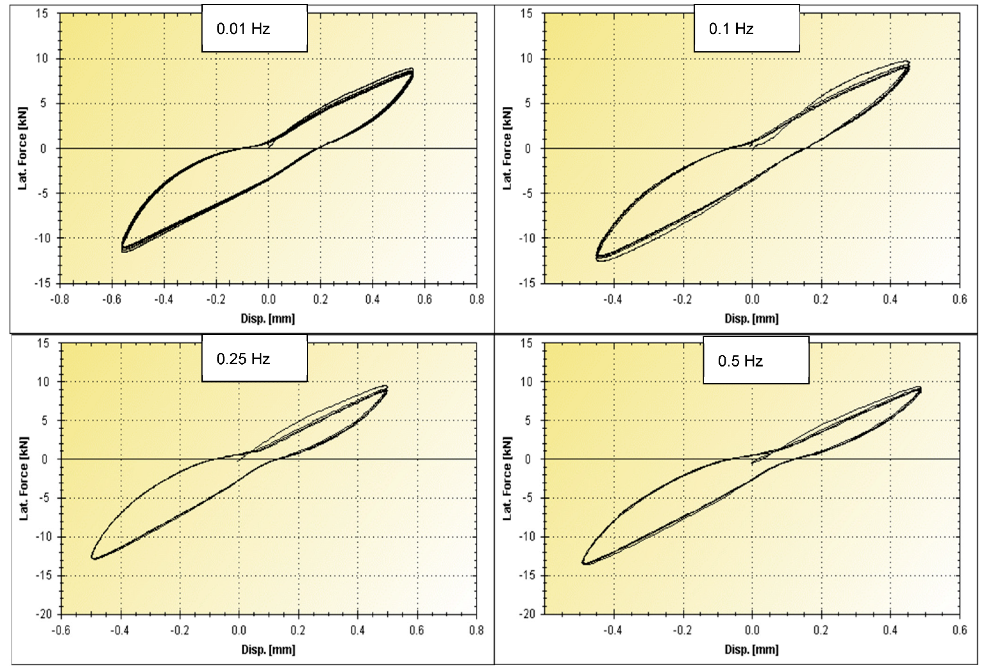
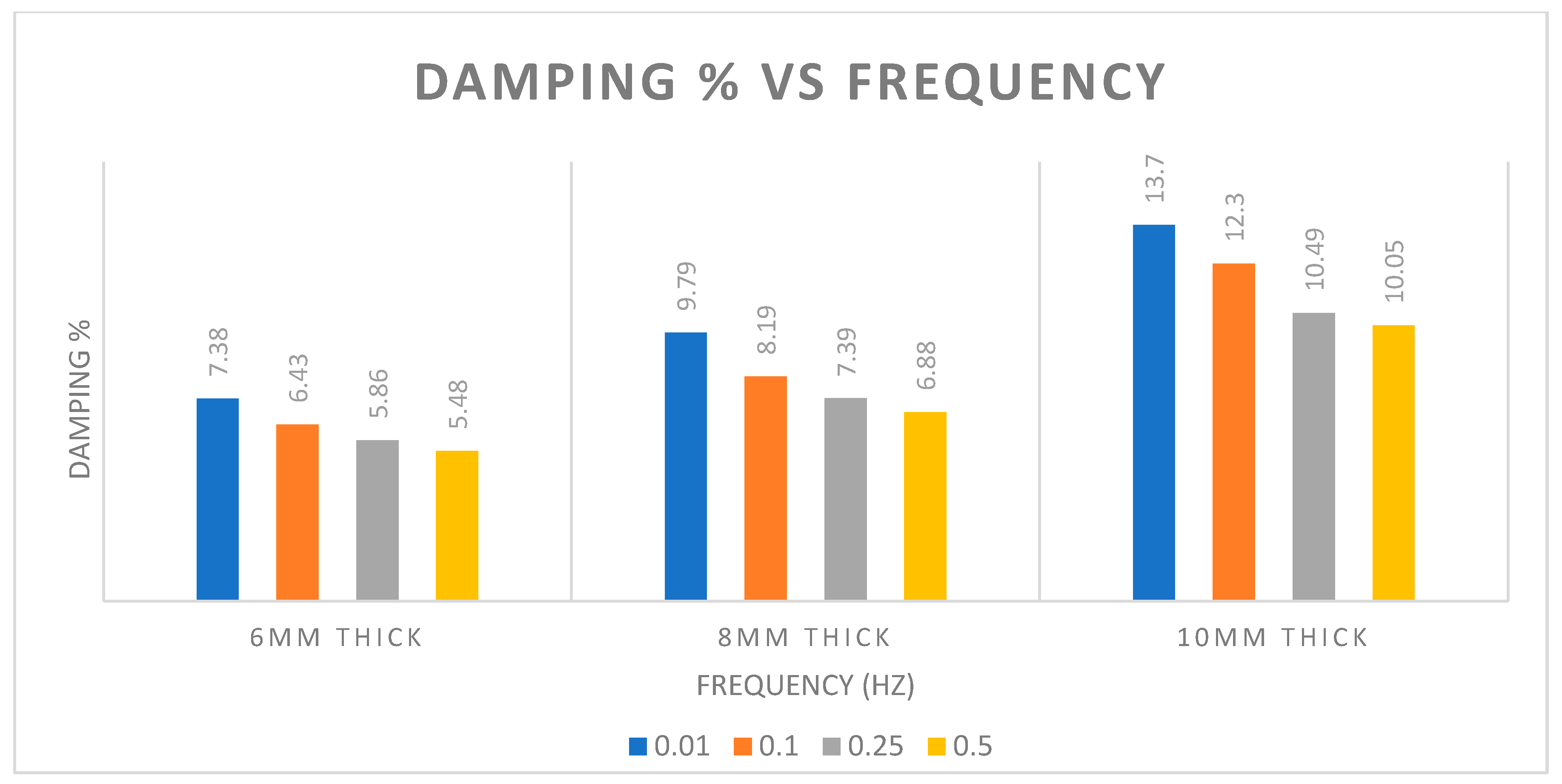
To further investigate the effects of rubber thickness and different frequencies on the damping characteristics, three more sample dampers of 6, 8, and 10 mm were tested using four frequencies of 0.01, 0.1, 0.25 Hz, and 0.5 Hz. The damping ratio result from the testing was obtained using the third cycle as per EN 15129:2009. All the data from the above tests are presented in Figure 8 and Table 4 for dampers that are 6 mm thick, Figure 9 and Table 5 for dampers 8 mm thick, and Figure 10 and Table 6 for dampers that are 10 mm thick. The results are summarized in Figure 11. According to the results, when using thinner rubber, the damping ratio percentage significantly decreased, especially from 10 mm to 8 mm. It was further reduced from 8 mm to 6 mm but at a slightly lower rate. When the rubber thickness is reduced, the allowable design pressure on rubber increases [28], and stiffness and Keff increase. However, the axial displacement under the same load was reduced. This significantly reduced the damping behavior that mitigated the force. The applied frequency affected the damping behavior of high-damping rubber. This can easily be explained by the fact that, at a higher frequency, the rubber stiffness is not fully utilized and thus does not provide more displacement. In other words, the applied force is not fully mobilized into the rubber material. This is illustrated in the above graph, according to which the damping ratio was reduced after the applied frequency was increased. Fortunately, the rate of the decrease in the damping ratio became slower when the frequency continued to increase. For instance, when using 10 mm thick rubber, the damping ratio was reduced from 13.7 Hz to 12.3 Hz when the frequency increased 10 times from 0.01 Hz to 0.1 Hz. However, the damping ratio rate was reduced from 13.7 Hz to 10.05 Hz, even though the frequency increased 50 times, from 0.01 Hz to 0.5 Hz.

5. Finite Element Analysis of Hyperelastic Composite Damper

5.1. FE Modeling

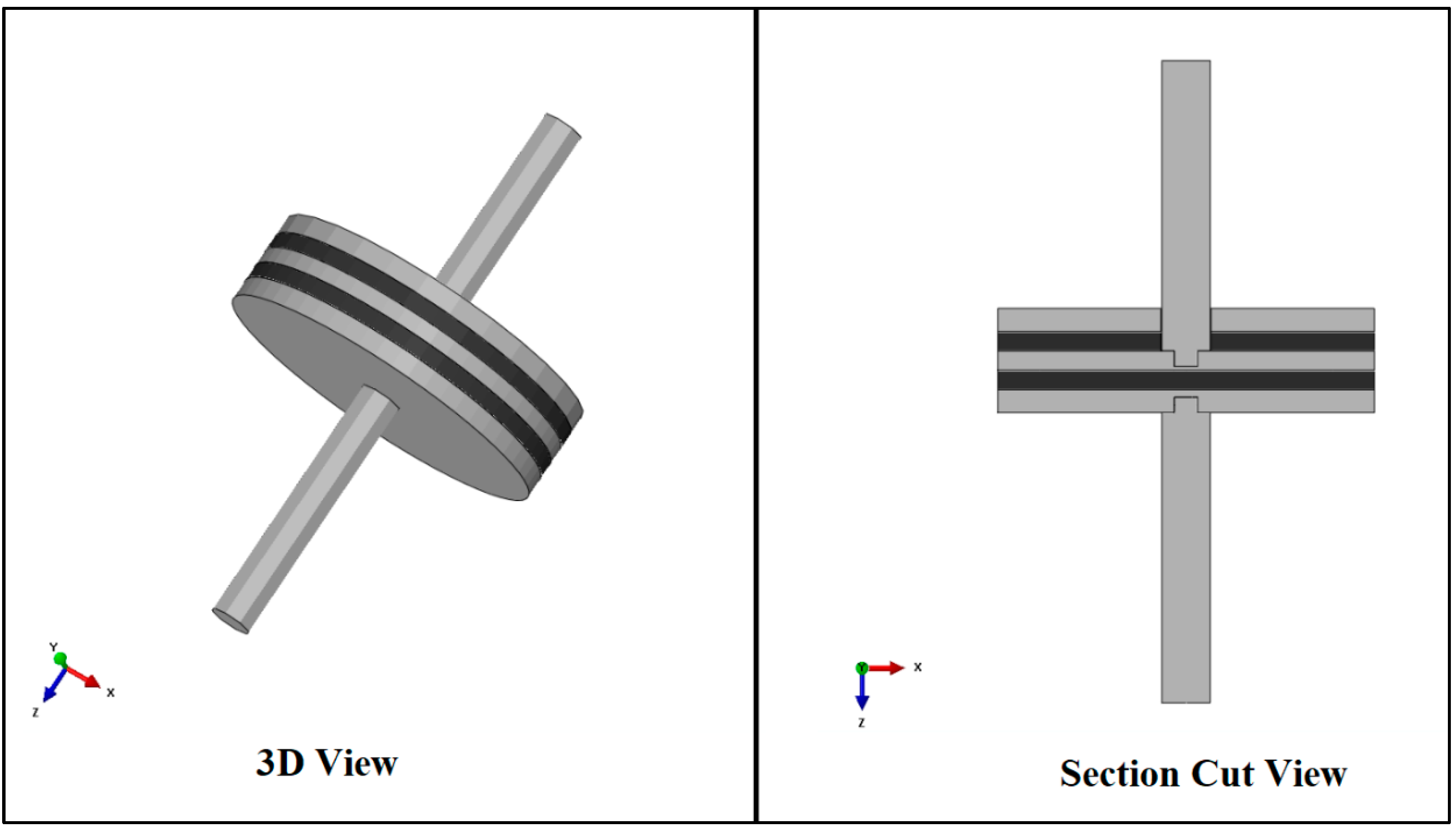
To corroborate the proposed hyperelastic composite material properties used for future studies, FE analyses were conducted. HECM properties in the modeling were simulated based on the laboratory results in Section 4 since the 10 mm thick HECM only provided more than a 10% damping ratio, as shown in Section 4. Thus, a detailed finite element analysis was performed using 10 mm thick damping at the loading frequency of 0.01 Hz and 0.5 Hz, respectively, where these two frequencies are covered in EN 15129. ABAQUS software was used at this stage due to its ability to consider the inelastic behavior of rubber elements.
Three-dimensional solid elements were used to define the steel plates and viscoelastic layers. The viscoelastic layers were fully bonded to the steel plates; therefore, tie constraints were used to simulate the interactions. Element types of C3D8R (8-node linear brick, reduced integration with hourglass control) and C3D20H (20-node quadratic brick, hybrid with linear pressure) were used for steel and viscoelastic layers, respectively. For boundary or restraint, one side of the damper was fully restrained against all translation and rotation movements, while the other side was free to move. Figure 12 shows the finite element model of the conventional viscoelastic damper in ABAQUS software.
The density of the viscoelastic material obtained was 1200 kg/m3. Both hyperelasticity and viscoelasticity properties were used to define the behavior of the composite material. ABAQUS uses the strain energy potential, rather than Young’s modulus and Poisson’s ratio, to relate stresses to strains for hyperelastic materials. The strain energy potential defines the strain energy stored in the material per unit of reference volume (volume in the initial configuration) as a function of the strain at that point in the material. Several forms of strain energy potentials are available in ABAQUS to model most commercial elastomers. Generally, for the hyperelastic material models available in ABAQUS, a strain energy potential can be defined directly by specifying material coefficients, or ABAQUS automatically determines approximate values for the coefficients through provided experimental test data. In this paper, the neo-Hookean model was used to define hyperelasticity through experimental tensile test data obtained for the composite material. The neo-Hookean model is recognized as the best method for predicting the nonlinear stress–strain behavior of materials undergoing large deformations with satisfactory approximation when the parameters are based on only one test. The meshing of the FE model is shown in Figure 13.
Viscoelasticity properties in ABAQUS are defined in four ways: the direct specification of the Prony series parameters, the inclusion of creep test data, the inclusion of relaxation test data, or the inclusion of frequency-dependent data obtained from sinusoidal oscillation experiments. To model the viscoelastic material in this research, viscoelasticity was implemented through the direct specification of the Prony series parameters. The Prony series represents the mechanical analogy of viscoelastic material behavior more rationally, where the linear elastic properties are represented by springs, and the time-dependent viscous properties are represented by the dashpots.

5.2. Validation of FE Model

For the validation of the FE model of the scaled-down hyperelastic composite damper, the performance of the FE model under dynamic loads was investigated. The aim was to check whether the dynamic responses of the simulated viscoelastic damper were in good agreement with the experimental results. For the validation of the dynamic performance of the viscoelastic damper model, displacement-controlled analysis was applied to the model under the frequency of 0.01 Hz and 0.5 Hz up to +0.43 mm. The load–displacement results obtained from the FE analysis were compared with the experimental results and are shown in Figure 14. It is obvious from the figures that the results of the experimental tests and FE model became stable after a few cycles. The shape of the hysteresis loops obtained from the FE model and experiment were in agreement.
The Prony series coefficients were derived based on the mechanical properties of the composite material used in the scaled-down damper at various frequencies and strains. Table 7 presents the Prony series coefficients used in HECM to generate the graphs in Figure 14, where g is the dimensionless shear relaxation modulus associated with relaxation times, respectively.

6. Conclusions

The results above demonstrated that the HECM, a type of HDR, is not limited to the shear behavior but also exhibits good performance in direct axial compression. The HECM can provide a damping ratio of approximately 10% to 13% under axial conditions instead of purely under shear conditions and, therefore, can be developed into a novel system for rubber dampers resisting axial forces in the near future. This damper is expected to provide similar performance and competitiveness as a viscous damper as long as the damping ratio is greater than 10% [27]. According to EN 15129:2009, the testing frequency used should be 0.5 Hz for the damping testing. The above result showed that the damping ratio was higher than 10% when using a 10 mm thick sample at 0.5 Hz. On the other hand, HECM can provide more durable and consistent behavior, which provides new advantages for the damper industry. This HECM can be used as a damper material under direct axial force conditions, such as those experienced by current viscous dampers. As a result, HECM can be used to develop a new damper for the industry in the near future.
Dampers should have larger deformation and higher axial capacity to accommodate the requirements of dynamic events on structures. Pure HECM is not sufficient to meet these requirements. Hence, a combination of HECM and layers of steel plates should be developed for further study.

Author Contributions

Conceptualization, C.G.T. and T.W.T.; methodology, C.G.T. and T.W.T.; software, T.W.T.; validation, C.G.T., and M.Z.J.; formal analysis, C.G.T. and T.W.T.; investigation, T.W.T.; data curation, T.W.T.; writing—original draft preparation, T.W.T.; writing—review and editing, C.G.T. and T.W.T.; supervision, M.Z.J.; funding acquisition, C.G.T. All authors have read and agreed to the published version of the manuscript.

Funding

Universiti Malaya Impact-Oriented Interdisciplinary Research Grant Programme (IIRG004B-2021IISS).

Data Availability Statement

The data presented in this study are available on request from the corresponding author. The data are not publicly available due to the confidentiality requirements of the lab.

Acknowledgments

This research was financially supported by the Universiti Malaya Impact-Oriented Interdisciplinary Research Grant Programme (IIRG004B-2021IISS). The testing facilities provided by Kossan Rubber Industries Bhd are gratefully acknowledged.

Conflicts of Interest

The authors declare that they have no affiliations with or involvement in any organization or entity with any financial interest in the subject matter or materials discussed in this manuscript.

List of Symbols

GShear modulus
γShear strain
ξ Viscous damping ratio
K b Effective stiffness
HArea of the hysteretic loop
d+The maximum displacement values in the cycle
dThe minimum displacement values in the cycle
F+The force values at maximum displacement
FThe force values at minimum displacement
ƒFrequency

References

  1. Gu, H.; Itoh, Y. Ageing Behaviour of Natural Rubber and High Damping Rubber Materials Used in Bridge Rubber Bearings. Adv. Struct. Eng. 2010, 13, 1105–1113. [Google Scholar] [CrossRef]
  2. Kerileng, K.; Dundu, M. Base Isolation Systems in Multi-Storey Structures. In Proceedings of the International Conference on Structural Engineering Research, Sydney, Australia, 20–22 November 2017; pp. 203–209. [Google Scholar]
  3. Samadian, D.; Ghafory-Ashtiany, M.; Naderpour, H.; Eghbali, M. Seismic resilience evaluation based on vulnerability curves for existing and retrofitted typical RC school buildings. Soil Dyn. Earthq. Eng. 2019, 127, 105844. [Google Scholar] [CrossRef]
  4. Huang, Z.; Zhang, D.; Pitilakis, K.; Tsinidis, G.; Huang, H.; Zhang, D.; Argyroudis, S. Resilience assessment of tunnels: Framework and application for tunnels in alluvial deposits exposed to seismic hazard. Soil Dyn. Earthq. Eng. 2022, 162, 107456. [Google Scholar] [CrossRef]
  5. Desai, M.; John, R. Seismic performance of base isolated multi-storey building. Int. J. Sci. Eng. Res. 2015, 6, 84–89. [Google Scholar]
  6. Park, K.H.; Fujiwara, Y.; Mazda, T.; Kajita, Y. Evaluation of mechanical properties considering hysteresis characteristic of high damping rubber bearing. J. Phys. Conf. Ser. 2020, 1687, 012019. [Google Scholar] [CrossRef]
  7. Atam, E. Friction Damper-Based Passive Vibration Control Assessment for Seismically-Excited Buildings Through Comparison With Active Control: A Case Study. IEEE Access 2018, 7, 4664–4675. [Google Scholar] [CrossRef]
  8. Yan, Y. Influence of High Damping Rubber Bearing on Seismic Performance of The Bridge. IOP Conf. Ser. Earth Environ. Sci. 2020, 510, 052058. [Google Scholar] [CrossRef]
  9. Fujita, S.; Fujita, T.; Kasahara, Y.; Suizu, Y.; Furuya, O.; Teramoto, T.; Kitamura, H. Energy Absorption Characteristics of High Damping Rubber Damper for Vibration Control of High-Rise Buildings; SMiRT-12; IASMiRT: Anaheim, CA, USA, 1993; pp. 243–248. [Google Scholar]
  10. Teramoto, T.; Kitamura, H.; Ozaki, H.; Furuya, O.; Morikawa, S.; Suzuki, S. Practical Application of high-damping rubber dampers to slender buildings. In Proceedings of the 11th World Conference on Earthquake Engineering WCEE, Acapulco, Mexico, 23–28 June 1996. [Google Scholar]
  11. Gan, Z.P.; Hayashikawa, T.; Matsumoto, T.; He, X.W. Seismic response analysis of base-isolated bridge subjected to long duration earthquake in low temperature environment. J. Struct. Eng. JSCE 2015, 61A, 335–343. [Google Scholar]
  12. Fuller, K.; Ahmadi, H.; Goodchild, I.R.; Magonette, G.; Taucer, F.; Dumoulin, C. Rubber-Based Energy Dissipators for Earthquake Protection of Structures. In Proceedings of the 12th WCEE, Auckland, New Zealand, 30 January–4 February 2000. [Google Scholar]
  13. Itoh, Y.; Gu, H.; Satoh, K.; Yamamoto, Y. Long-Term Deterioration of High Damping Rubber Bridge Bearing. Doboku Gakkai Ronbunshuu A 2006, 62, 595–607. [Google Scholar] [CrossRef] [Green Version]
  14. Castaldo, P.; Tubaldi, E.; Selvi, F.; Gioiella, L. Seismic performance of an existing RC structure retrofitted with buckling restrained braces. J. Build. Eng. 2020, 33, 101688. [Google Scholar] [CrossRef]
  15. Min, K.-W.; Kim, J.; Kim, Y.-W. Design and test of tuned liquid mass dampers for attenuation of the wind responses of a full scale building. Smart Mater. Struct. 2014, 23, 045020. [Google Scholar] [CrossRef]
  16. Zhu, R.; Guo, T.; Mwangilwa, F. Development and test of a self-centering fluidic viscous damper. Adv. Struct. Eng. 2020, 23, 2835–2849. [Google Scholar] [CrossRef]
  17. Dolati, S.S.K.; Mehrabi, A.; Dolati, S.S.K. Application of Viscous Damper and Laminated Rubber Bearing Pads for Bridges in Seismic Regions. Metals 2021, 11, 1666. [Google Scholar] [CrossRef]
  18. Sarwar, W. Viscoelastic Material as Energy Dissipater Viscoelastic Damper for Building Structures to Mitigate the Seismic Vibration. Civ. Environ. Eng. Rep. 2019, 29, 41–49. [Google Scholar] [CrossRef] [Green Version]
  19. Kanitkar, R.; Harms, M.; Crosby, P.; Lai, M.L. Seismic retrofit of a steel moment frame structure using vis-coe-lastic dampers. J. Earthq. Technol. 1998, 35, 207–219. [Google Scholar]
  20. Xu, Y.; Xu, Z.; Guo, Y.; Huang, X.; Dong, Y.; Li, Q. Dynamic Properties and Energy Dissipation Study of Sandwich Viscoelastic Damper Considering Temperature Influence. Buildings 2021, 11, 470. [Google Scholar] [CrossRef]
  21. Constantinou, M.C.; Symans, M.D. Experimental & Analytical Investigation of Seismic Response of Structures with Supplemental Fluid Viscous Dampers; NCEER-92-0032; National Center for Earthquake Engineering Research: Buffalo, NY, USA, 1992. [Google Scholar]
  22. Chang, K.C.; Tsai, M.H.; Chang, Y.H.; Lai, M.L. Temperature Rise Effect of Viscoelastically Damped Structures Under Strong Earthquake Ground Motions. J. Mech. 1998, 14, 125–135. [Google Scholar] [CrossRef]
  23. Konstantinidis, D.; Makris, N.; Kelly, J.M. In-situ condition assessment of seismic fluid dampers: Experimental studies and challenges. Meccanica 2014, 50, 323–340. [Google Scholar] [CrossRef]
  24. Alexandru, C. Variety of displacement Dependent Devices Used for Bridges and Viaducts Certified By ICECON SERT SRL. Acta Uiversitatis Cibniensis-Tech. Ser. 2017, 69, 121–129. [Google Scholar] [CrossRef]
  25. Sadek, F.; Mohraz, B.; Taylor, A.W.; Chung, R.M. Passive Energy Dissipating Devices for Sesismic Applications. In Building and Fire Research Laboratory; Report NISTIR 5923; National Institute of Standarts and Technology: Gaithersburg, MD, USA, 1996. [Google Scholar]
  26. EN 15129; Anti-Seismic Devices. Comité Européen de Normalisation (CEN): Brussels, Belgium, 2009.
  27. Reza, A.M. A study on the damping ratio of the viscous fluid dampers in the braced frames. Eur. Online J. Nat. Soc. Sci. 2014, 3, 1223–1235. [Google Scholar]
  28. EN 1337-3:2005; Structural Bearings—Part 3: Elastomeric Bearings. Technical Committee CEN/TC 167. BSI: London, UK, 2009.
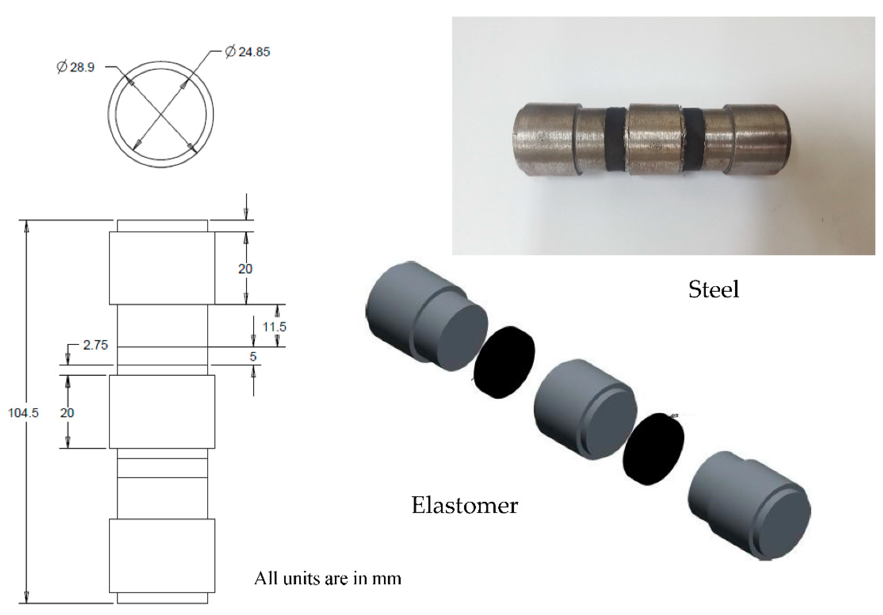
Figure 1. Configuration of double-shear test sample.
Buildings 12 01917 g001
Figure 2. Double-shear testing using INSTRON servo-hydraulic testing machine.
Buildings 12 01917 g002
Figure 3. Force–displacement test curve graph.
Buildings 12 01917 g003
Figure 4. Typical isometric view and dimension of the proposed scaled-down hyperelastic composite damper.
Buildings 12 01917 g004
Figure 5. Testing on the product sample using Dynacell machine.
Buildings 12 01917 g005
Figure 6. Force–displacement graph for sample under compression and tension.
Buildings 12 01917 g006
Figure 7. Product testing, showing force–displacement test and results for product under cyclical compression.
Buildings 12 01917 g007
Figure 8. Plot of device testing, showing force–displacement for 6 mm thick HDR material at different frequencies.
Buildings 12 01917 g008
Figure 9. Plot of device testing, showing force–displacement for 8 mm thick HDR material at different frequencies.
Buildings 12 01917 g009
Figure 10. Plot of device testing, showing force–displacement for 10 mm thick HDR material at different frequencies.
Buildings 12 01917 g010
Figure 11. Plot of damping result with different thicknesses of rubber and frequencies.
Buildings 12 01917 g011
Figure 12. The 3D model and section view of the FE model.
Buildings 12 01917 g012
Figure 13. Meshing and stress contour of the FE model.
Buildings 12 01917 g013
Figure 14. Comparison of load–displacement curves under (a) 0.01 Hz and (b) 0.5 Hz.
Buildings 12 01917 g014
Table 1. Result data for force–displacement.
CycleGγd+dF+FHKbξƒ
-(MPa)(%)(mm)(mm)(kN)(kN)(kN·mm)(kN/mm)(%)(Hz)
10.428850.62.7806−2.78130.10424−0.108630.308540.0382716.590.03
20.434350.62.7806−2.78130.10169−0.11390.29410.0387615.610.03
30.440150.62.7804−2.78120.10211−0.116350.291070.0392815.250.03
40.444150.62.7806−2.78130.10261−0.117880.289530.0396415.030.03
50.404875.84.171−4.17160.14277−0.158610.60630.0361315.350.03
Table 2. Result data for force–displacement under tension and compression.
Cycled+dF+FHKbξƒ
-(mm)(mm)(kN)(kN)(kN·mm)(kN/mm)(%)(Hz)
10.22448−0.221999.8674−10.1981.146644.9428.150.00995
20.22425−0.221829.7901−10.0441.168744.4638.410.01002
30.22486−0.222029.7799−9.86741.170043.9668.480.00999
Table 3. Result data for force–displacement under pure compression.
Cycled+dF+FHKbξƒ
-(mm)(mm)(kN)(kN)(kN·mm)(kN/mm)(%)(Hz)
10.5585−0.56298.6552−11.3074.863517.80113.830.01
20.5584−0.5638.3737−11.0554.724417.32613.80.01
30.5584−0.56298.2284−10.8834.613117.04413.70.01
Table 4. Result data for 6 mm thick HDR material at different frequencies.
6 mm Thick Rubber
Cycle
d+dF+FHKbξƒ
-(mm)(mm)(kN)(kN)(kN·mm)(kN/mm)(%)(Hz)
10.2798−0.28049.9608−11.3441.4538.0317.730.01
20.2799−0.28069.7562−11.0471.364437.1157.450.01
30.2798−0.28049.5962−10.7941.317936.3977.350.01
10.25449−0.24968.72−12.3771.07241.8526.420.099
20.25465−0.24998.5428−12.1251.060740.9646.480.1001
30.25407−0.24998.53−12.0691.048140.8736.430.0999
10.28144−0.27599.5915−13.5381.190341.55.880.2447
20.27696−0.27549.321−13.3441.156241.0335.880.2503
30.27609−0.27509.3281−13.2781.147241.0195.860.2498
10.27821−0.26429.5691−12.9541.032541.5265.380.4871
20.2656−0.26569.0762−12.8731.002541.3185.470.4995
30.26711−0.26469.0518−12.91.005141.2865.480.4995
Table 5. Result data for 8 mm thick HDR material at different frequencies.
8 mm Thick Rubber
Cycle
d+dF+FHKbξƒ
-(mm)(mm)(kN)(kN)(kN·mm)(kN/mm)(%)(Hz)
10.4484−0.45249.101−10.932.989322.23610.550.01
20.4484−0.45248.7585−10.5282.738321.41110.030.01
30.4483−0.45248.582−10.312.617120.9759.790.01
10.45331−0.45279.143−11.7122.529923.0198.520.1
20.45295−0.45209.0148−11.6122.402522.7938.190.1
30.45308−0.45248.9376−11.292.355722.3388.190.1
10.44954−0.44789.4756−12.3752.398924.357.790.248
20.44757−0.44819.2494−12.2552.240924.0097.410.2494
30.44712−0.44719.199−12.0172.202523.7267.390.25
10.49519−0.483610.535−14.1112.76125.1797.290.4924
20.48599−0.484910.171−13.8892.521224.7816.870.4995
30.48632−0.48499.9704−13.5962.47324.2646.880.5
Table 6. Result data for 10 mm thick HDR material at different frequencies.
10 mm Thick Rubber
Cycle
d+dF+FHKbξƒ
-(mm)(mm)(kN)(kN)(kN·mm)(kN/mm)(%)(Hz)
10.5585−0.56298.6552−11.3074.863517.80113.830.01
20.5584−0.5638.3737−11.0554.724417.32613.80.01
30.5584−0.56298.2284−10.8834.613117.04413.70.01
10.4556−0.45149.5276−12.2663.932224.02912.670.1002
20.4556−0.45079.0664−11.9733.740123.21612.490.1
30.4551−0.45058.9405−11.7543.621522.85312.30.1
10.5028−0.49899.2421−12.6723.920321.87811.370.2466
20.5000−0.49958.7878−12.6073.605421.40410.730.2504
30.4998−0.49838.6859−12.7393.523821.46610.490.2503
10.4893−0.49149.0509−13.3693.542122.86110.260.4916
20.4898−0.48968.9326−13.4443.349922.84610.180.5003
30.4894−0.48958.8238−13.1933.278122.49210.050.5
Table 7. Prony series coefficients of HECM.
gτ
0.012795.00 × 10−4
0.275230.005
0.280050.0159
0.204020.05
0.107780.159
0.059280.5
0.028671.59
0.015495
0.0075315.9
0.0039950
0.00195159
0.00106500
0.0004725241590
0.0003137335000
7.94 × 10−515,900
0.00012125850,000
3.59 × 10−5500,000
1.14 × 10−55,000,000
Publisher’s Note: MDPI stays neutral with regard to jurisdictional claims in published maps and institutional affiliations.