Article

Influence of User Behaviour on the Functioning and Performance of Passive Phase-Change Material Systems after More Than a Decade of Operation

1
Group Heat and Cold Storages, Fraunhofer Institute for Solar Energy Systems ISE, Heidenhofstr. 2, 79110 Freiburg, Germany
2
Karlsruhe Institute of Technology, Englerstr. 7, 76131 Karlsruhe, Germany
*
Author to whom correspondence should be addressed.
Buildings 2022, 12(11), 1797; https://doi.org/10.3390/buildings12111797
Submission received: 21 July 2022 / Revised: 14 October 2022 / Accepted: 18 October 2022 / Published: 26 October 2022
(This article belongs to the Section Building Materials, and Repair & Renovation)

Abstract

:
Phase-change materials (PCM) in buildings are considered a promising option to prevent overheating in warm seasons. Numerous studies have shown a noticeable improvement in thermal comfort through PCM, but in real applications they have often underperformed. User behaviour is often neglected as an important factor in determining PCM performance and might be a limiting factor. Another factor could be time-dependent degradation, which has also been scarcely researched so far. We used simulations within two case studies to investigate whether the PCM applications, each of which had been in operation for more than ten years, were still functioning from a technical perspective and what influence user behaviour had on their performance. We found that the PCM applications still had a positive influence on the thermal performance of the rooms, although the effect due to behavioural optimizations was significantly greater. The PCM was able to reduce the time of discomfort by 9–45% in the baseline scenario with real documented user behaviour in both rooms. Improved user practices increased the reduction in discomfort to 33–52%. For future studies evaluating PCM and its use, we recommend considering realistic user habits, as implementing optimal behaviour could lead to an overestimation of PCM performance and dissatisfaction with the technology.

1. Introduction

For several decades, the use of latent heat storage has been viewed as a promising way to improve comfort in buildings in a climate-friendly way [1,2,3,4]. Phase-change materials (PCMs)—mainly paraffins or salt hydrates—are placed in central tanks or decentrally in walls and ceilings to prevent buildings from overheating during the day. To do this, the PCMs absorb the heat by undergoing an almost isothermal phase change from solid to liquid. At night, the regeneration of the material takes place as the heat is released into the environment in the inverse process and the PCM solidifies again.
The building integration of PCM is well explored. Several studies have validated their positive effects on thermal conditions: temperature highs have been diminished, and daytime highs have been postponed to evening or nighttime hours with cooler surrounding temperatures (e.g., [5,6,7,8,9,10]). However, most of the studies on PCMs are focused on one goal, namely the optimization of the PCMs, which includes the questions of where to install the PCMs and which melting range and thickness should be chosen. Moreover, almost all these studies were laboratory, experimental or simulation studies. Analyses of real applications make up only a small part of the studies [11]. Most of the available studies are based on simulations, either completely omitting the user presence or assuming an ideal behaviour of people. At the same time, it is known that the energy demand of a building, its thermal performance and user satisfaction depend significantly on the behaviour of the occupants [12,13]. Occupant behaviour is also a key influencing factor in PCM building applications, especially in passive systems that use night ventilation to regenerate the PCM material; the fundamental functionality depends on user behaviour, which is why it strongly influences thermal comfort conditions [14].
Only a few evaluations of realized PCM applications in buildings after several years of operation can be found in the literature. However, there is evidence that performance gaps between predicted and actual benefits frequently occur [11]. An important cause for the underperformance of PCM applications relates to the actual or real behaviour of the users. They are often insufficiently informed and are not aware of the importance of consistent night ventilation. In addition, room utilization that deviates from the planning, for example if more people use a room than planned or a mechanical ventilation system is not used contrary to the planning, is considered problematic [15,16,17]. Several authors emphasize the importance of studies that investigate the performance of PCM applications in real applications with real user behaviour. In the future, these can contribute to narrowing the performance gap between planning and reality and strengthen confidence in building simulations with PCM [11,17,18].
Studies regarding PCM performance in real buildings have mostly been conducted using simulations. There are hardly any experimental studies that report the performance of PCM in a real house with occupants. To our knowledge, there are only two existing publications at present that have investigated the performance of PCM applications in real homes with real inhabitants. The effects of PCM in a newly built passive semi-detached house were investigated in one study. The researchers performed measurements and building simulations with the EnergyPlus software for this purpose [19]. They found that the PCM enhanced thermal comfort conditions and lowered the overheating time by 50% [20]. Jamil et al., in another study [15], equipped a room in a domestic building in Melbourne with macro-encapsulated PCM and recorded the rooms’ temperature curve for two summer months. Based on the experimental data, the authors set up a building model to provide a quantification of the impact of the PCM. They found that the presence of PCM led to a temperature lowering of up to 1.1 °C and a 34 % drop in the number of hours of thermal discomfort. The two studies came to the conclusion that occupant behaviour has a major influence on thermal comfort. Sage-Lauck and Sailor even drew the conclusion that “it is likely, that variations in user behaviour result in larger effects on building energy use and thermal comfort than does the latent and sensible cooling benefits of the PCM” [20].
An additional aspect so far overlooked in research is long-term functionality. Manufacturers promise that building materials modified with Micronal PCM will maintain their function for decades without having to be renewed [21]. So far, however, there have only been individual publications on how PCM materials perform after several years of real-life operation out of the lab. To the best of our knowledge, the durability of PCM systems in practice has been studied in only three studies. Cellat et al. [22] analysed the efficiency of PCM concrete in a test cabin two years after construction. They found that the PCM could lower the room temperature by up to 2 °C and that after two years no loss of performance could be noticed. The thermal and mechanical characteristics of a house-like cabin built in 2005 out of PCM concrete were analysed by Cabeza et al. [23]. They found no changes in the thermal performance of the PCM in this test arrangement after ten years and therefore suggested that no degradation had taken place. The third study in this thematic focus was published by the authors of this paper [17]. The published results indicated a slight decrease in PCM functionality.
Due to the limited number of studies in this context and the different outcomes, there is the possibility that ageing and a related reduction in the heat storage capacity of PCM applications occur more strongly in reality than has been observed in laboratory tests and experimental setups so far. Therefore, in addition to the non-optimal behaviour of the users, as a second reason for the discrepancy between real and simulated PCM performance, time-dependent degradation comes into consideration.
An evaluation of PCM building applications after ten or more years in buildings in real use with a focus on the behaviour of the users does not yet exist. Since buildings are used for several decades, this information seems to us to be very valuable for architects, builders, and craftsmen, not least to improve the acceptance of PCM products. With our study, we would like to close this research gap and provide answers to the following questions based on our analyses:
  • Do PCMs still function from a technical point of view after being in use for more than a decade?
  • How does user behaviour influence the performance of the PCM?
  • Is there potential for improvement through behavioural changes on the part of the users?

2. Approach and Methods

Using two case studies, we investigated the extent to which the behaviour of users influenced the benefits of PCM for the thermal conduct of the rooms. For this purpose, various indoor climate-related data were recorded in two buildings, each in a room equipped with PCM, over a period of several months during the summer of 2018. Models of the rooms were then created using SketchUp software and the OpenStudio Extension. Subsequently, these models were imported into EnergyPlus and thermal simulations were carried out with them. The collected measurement data were used to calibrate the simulation models and to determine the actual PCM capacity. After successful model validation, these were taken to investigate how user behaviour affected PCM performance based on three different behavioural scenarios (Figure 1).

2.1. Two Case Studies

2.1.1. The Sonnenschiff Building

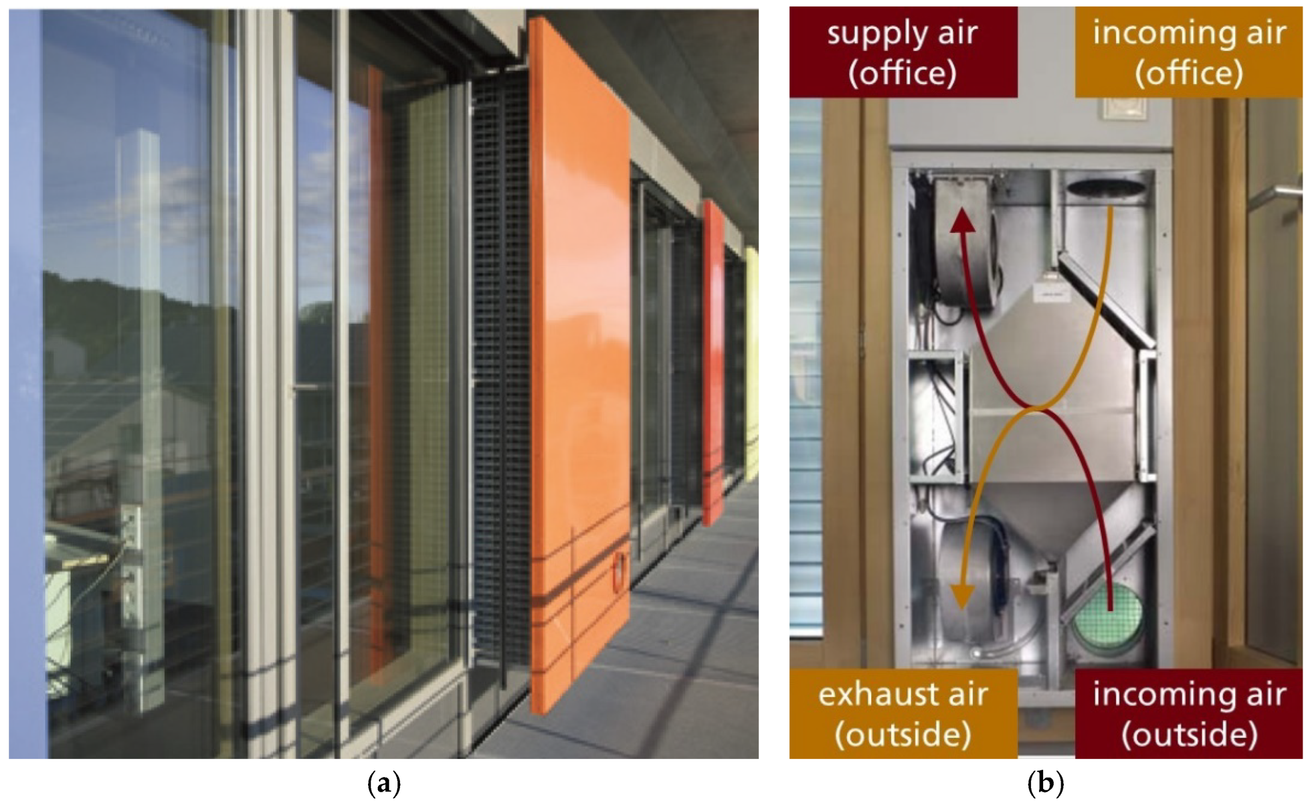
Located on the southeastern outskirts of Freiburg in southern Germany, the Sonnenschiff (Figure 2) is situated in the comparatively young district of Vauban. It was constructed in 2004 and provides nine penthouse apartments as well as space for commercial offices, shopping and medical practices. Designed as a plus-energy building, the Sun Ship consists of solid concrete ceilings and floors, while the partition walls contain little thermal mass. A lightweight post-and-beam construction forms the exterior façade. The light walls on the upper floor are covered with Smartboards, i.e., PCM-containing gypsum boards, to increase the thermal mass of the structure (Figure A2). This is to enhance the perceived thermal comfort during the warm season. The gypsum boards, called Smartboard 23, include microencapsulated paraffin wax produced by BASF [24], having a melting range of 23–26 °C [25]. To regenerate the passive PCM system, a night ventilation system composed of ventilation panels and a cross-flow heat exchanger is incorporated into the planning (Figure 3). A room on the east side of the building was analysed from 16th June through 15th September of 2018 and, during this period, it was regularly used by one person (More details about the building and the modelling as well as details about the monitored parameters can be found in our previous publication: Obergfell et al. [17]).

2.1.2. Classroom of a Secondary School

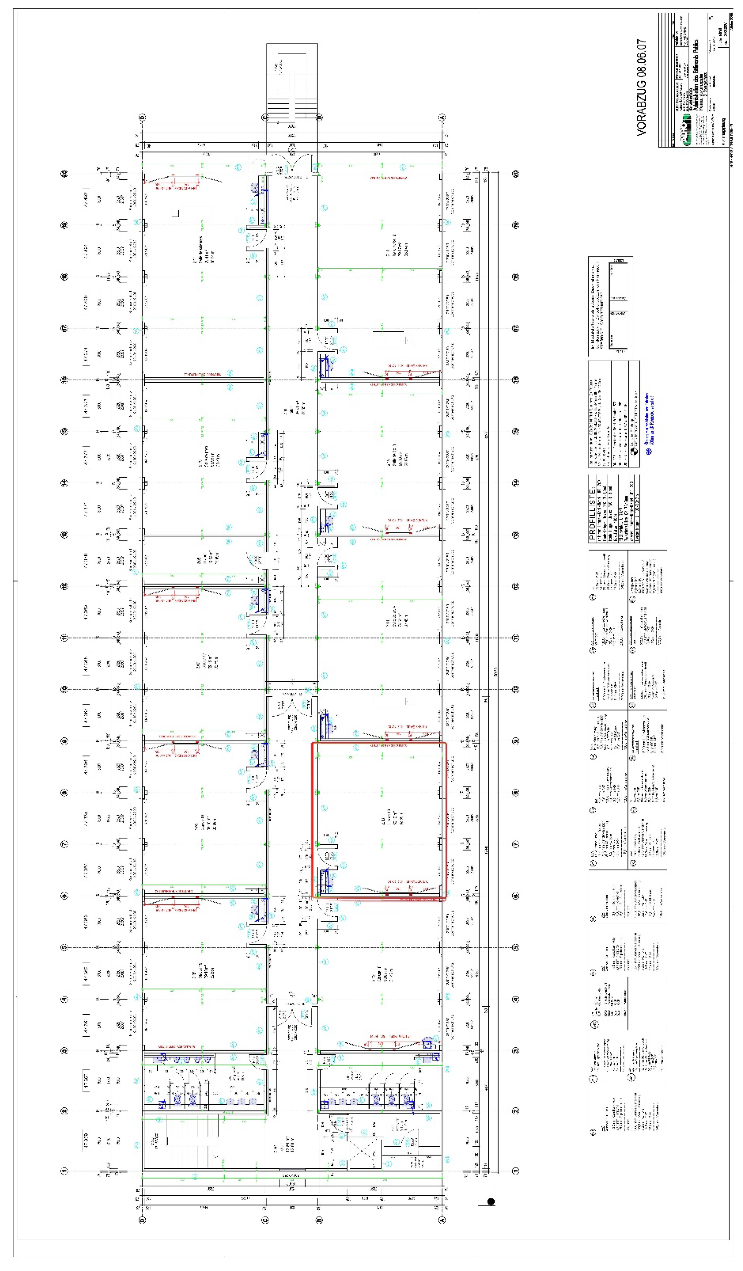
The second building investigated was the secondary school Nordstadt Lycee in Diekirch, Luxembourg. The building was built in 2007 and is also equipped with the PCM-containing plasterboards Smartboard 23. These are installed in the ceilings and some interior walls. The building was designed as a passive facility without an active cooling unit. Regeneration of the PCM products was planned to be ensured by opened windows and room doors during the night. The classroom investigated is located on the first floor and has three openable window wings with external sun protection (Figure 4). The construction of the walls, ceiling and floor was taken from internal planning documents from 2007 (a layout of the floor can be found in Figure A3). The room was normally used by a class of approximately 25 students and one teacher from Monday to Friday in the period from 7:00 to 17:00 according to the class schedule. The monitoring in this building took place from 1st June through 27th June of 2018.

2.2. Model Setup, Integration of PCM and Validation in EnergyPlus

2.2.1. Model Setup

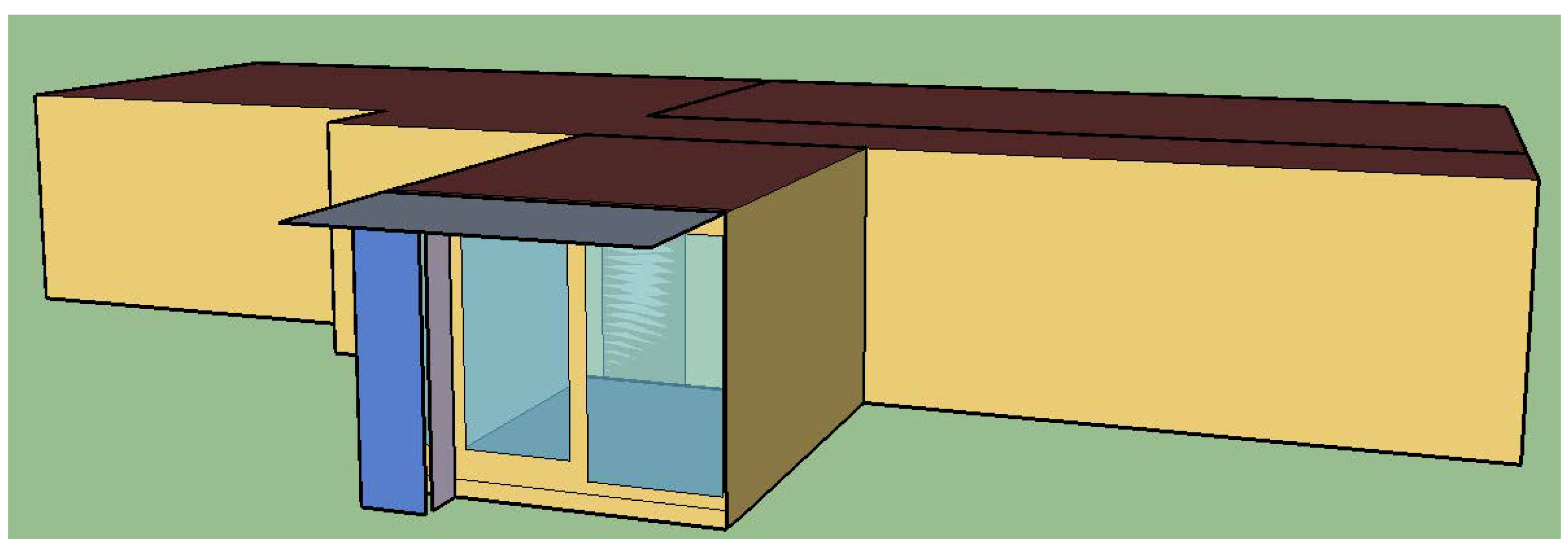
First, the respective room geometries and their surrounding environments were created in the software SketchUp using the OpenStudio extension (Figure 5 and Figure 6) and then exported as an EnergyPlus file. In the next step, all the relevant materials, boundary conditions and constructions were prepared. Finally, the corresponding properties were assigned to all the surfaces within the model (cf. Table A1 and Table A2). It is important to highlight the fact that not all materials along with their physical and thermal properties, the order of layers within the constructions and the thickness of the latter were known. Therefore, we had to make different assumptions where corresponding information was missing. The properties of standard materials used in the model were obtained from a U-value calculator available online, which contained a reliable database and followed standards applied in Germany [27].
The presence of people inside the office was detected by a motion sensor with a binary outcome of 1 (people were present) and 0 (no one present). When people were present, an internal gain of 120 W and 130 W per person for the office and classroom, respectively, were considered [19]. Internal gains through pupils are usually slightly higher than those of a working adult. Internal gains attributable to the use of devices such as computers and printers, as well as the use of ceiling lamps in the office room were neglected. The frequency of their use was unknown to us; therefore, they were not included in the model. For the classroom, in contrast, we assumed that, in addition to the internal gains from people, the light was also basically always switched on when people were present.
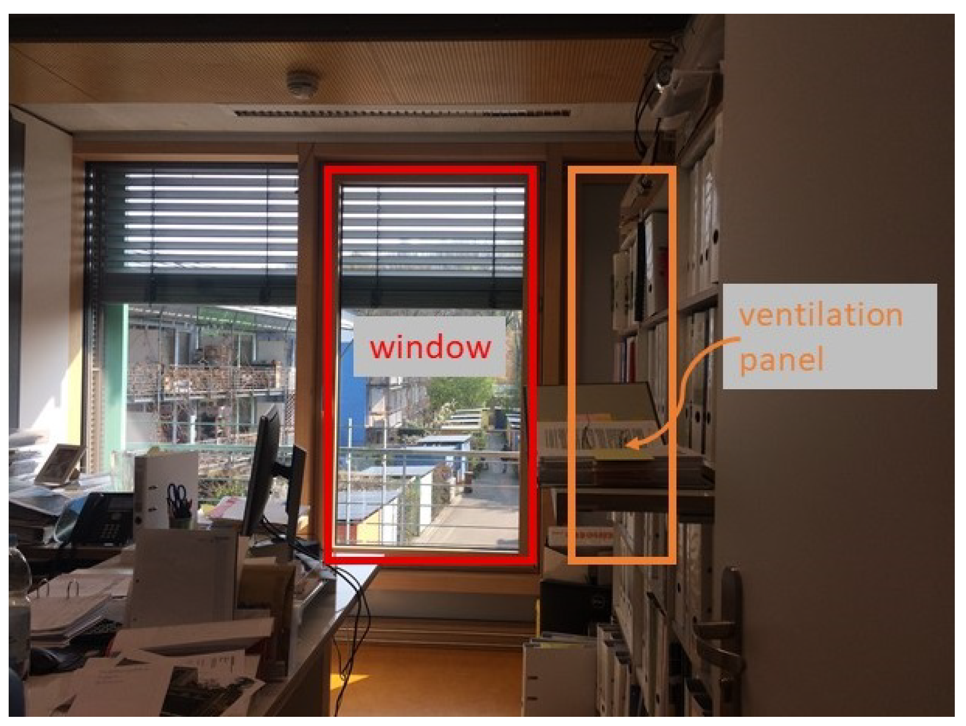
The office room in the Sonnenschiff is equipped with a large window that can be opened or closed and a ventilation panel that can also be fully opened or tilted (Figure 7). The operable windows in the classroom can only be fully opened or closed, analogous to the window in the office. For each position of the windows and ventilation panel (open, tilted and closed), we defined different infiltration values by first considering the airtightness of the building for when all windows were closed, which was defined to be equal to 0.3 air changes per hour (ACH). We selected this value based on the standard defined by the Passive House Institute, which must be met for a construction to be considered energy efficient [27]. The values used for the open and tilted positions were varied during the calibration process, to be discussed later, to adjust the simulation results to the measured data.
Using the measured data, we set up schedules to define when the rooms were occupied, when doors and windows were opened, closed or tilted, as well as the instances when the window shades were activated based on the measured illuminance. From these dates, ASCII files were generated for each building and schedule containing hourly data for the months of May through September. Simulation results were analysed for the period of 16th June through 15th September for the office room in the Sonnenschiff and June through July for the secondary school. The monitoring setup as well as the sensors and their properties are described in Obergfell et al. [17], chapter 2.4.
Likewise, we set up the shading schedules based on the measured illuminances at the center of the windows. Therefore, we compared the measured illuminance with the incident solar irradiance at the same window from the EnergyPlus simulation to determine when the window shades were being used. In the simulation, just the binary information unshaded and fully shaded was used, and partial shading was not considered.
The final step in creating the models was to calibrate them using the measured operative temperatures in periods were the PCM was inactive, meaning Top below 23 °C or above 26 °C were used. During this process, different calibration parameters were adjusted until the simulation results satisfactorily correlated with the measurement data. The objective functions to be optimized were defined as the coefficient of determination R2 and the RMSE. The coefficient of determination R2 provides a measure of how well the model fits the observed data [28]. An accepted R2 value varies greatly depending on the area of study and the desired accuracy of the model in question. Nevertheless, in general, an R2 value of larger than 0.60 is considered to be acceptable [29]. Furthermore, the difference between the simulation results and the measured data during the calibration process was evaluated by calculating the root mean square error (RMSE) where a value of less than or equal to 1 K was targeted [30]. The iterations of the calibration processes were performed manually. As we had to make assumptions in some places for the model setup, we varied several construction and operating parameters during the calibration process. These included thermal properties of the façades, the windows and the thicknesses of the concrete layers in the floors and ceilings. In addition, the models showed a great sensitivity to changes in the amount of air flow coming from the outside environment (i.e., natural ventilation). As the position of the windows (open, closed or tilted) could be determined from the data of the measurement campaign, only the amount of ACH defined for each window position had to be adjusted during the model calibration, given that these values were unknown. After multiple iterations, we considered the models to be successfully calibrated after reaching R2 values of 0.91 and 0.62 and RMSE of 0.44 K and 0.97 K for office model and classroom model, respectively.

2.2.2. Integration of PCM

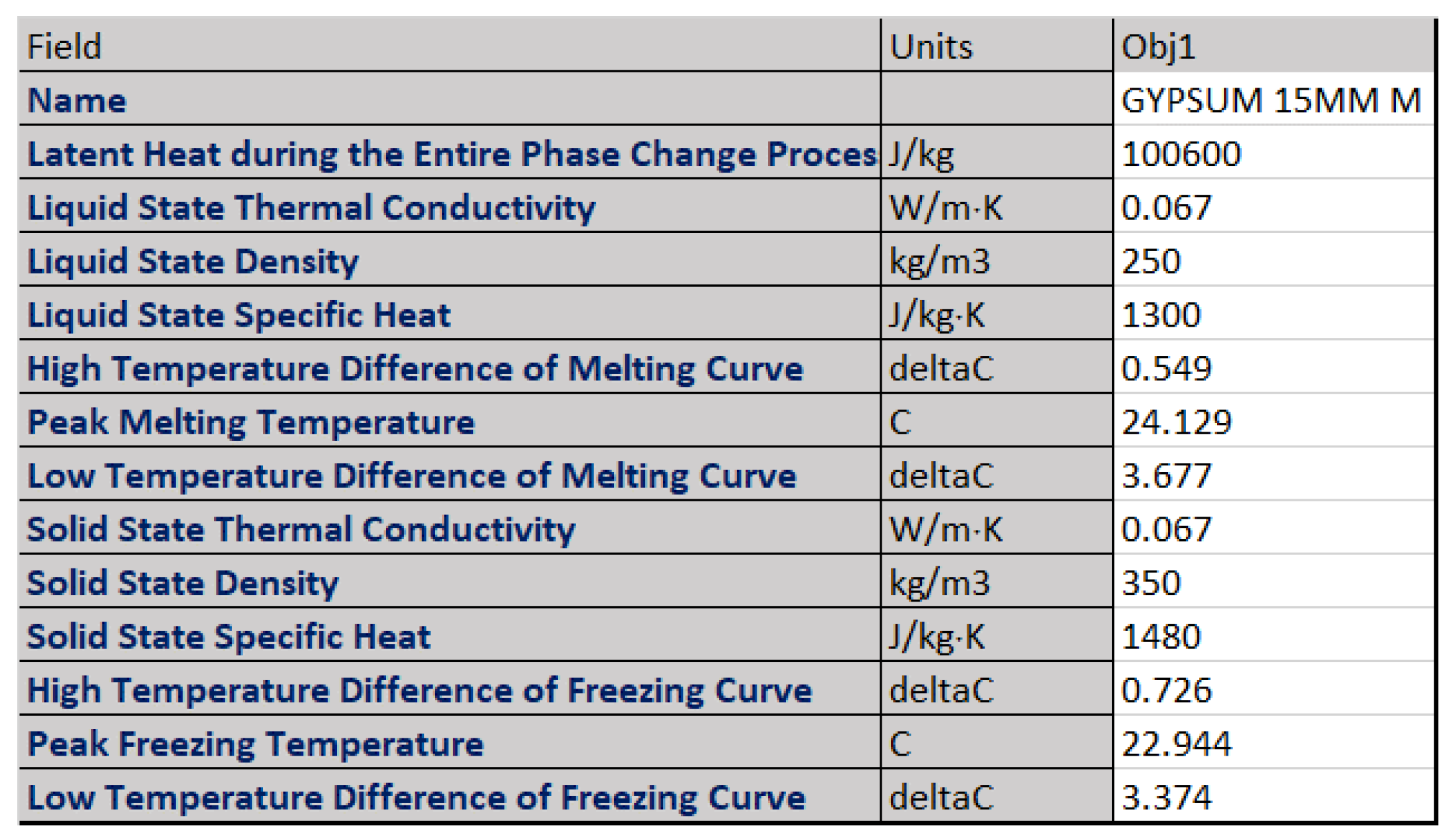
EnergyPlus enables the integration of PCMs in two different ways: the conventional enthalpy temperature method and the hysteresis method. Both methods can reproduce the influence of PCMs on the indoor climate well (A comprehensive comparative analysis of the two functions can be found in Al-Janabi & Kavgic [31]). However, the possibility of taking hysteresis into account, which is the frequently observed peculiarity that the curves of melting and crystallization differ [32], seemed more precise in our case. In doing so, the software employed a conduction finite difference algorithm when PCMs were included in the model. This supplemented the already-operating algorithm without PCMs, but allowed the inclusion of materials with more advanced thermal properties [33]. As previously stated, the temperature-dependent enthalpy data for the melting and solidification processes obtained from measurements with differential scanning calorimetry (DSC) facility were performed by Fraunhofer ISE (Figure A1). Where own measurements were not possible, values were taken from the literature. The initial latent heat storage capacity of the Smartboard 23 was equal to 100.6 kJ/kg (between 5 and 27 °C). As presented in Obergfell et al. [17], the DSC measurements of different PCM samples had shown that the storage capacity of some microencapsulated PCMs had decreased after several years of operation, which could be an indication of degradation or—more likely—diffusion of the paraffin. Based on these findings, in the next step of calibration, we varied the PCM capacity from 100 to 0% of the original capacity to obtain information about the current condition of the PCM in our two specific cases (cf. step 3 in Figure 1). The simulation results of the PCM capacity variations were compared with the measured data from a period in which the PCM was active, and the associated coefficients of goodness were determined.
It turned out that none of the models were clearly the best fit for the Solar Ship. The coefficient of determination was best for the 100% scenario with R2 = 0.66 but was only slightly lower for 75 and 50% with R2 = 0.65 (In our earlier publication [17], slightly different values were found at this point. The reason for this is that an error was discovered in the model in the meantime, which has now been corrected. The corrected simulation model led to slightly different results). The scenario with the best R2 value also had the worst RMSE value of 0.60 K, while the 50% scenario achieved the best value with 0.52 K. Therefore, it is likely that the actual PCM capacity was somewhere in the range between 50 and 100% of the original capacity. Due to the lack of clarity, further simulations were each carried out with the two PCM capacities. The corresponding results are therefore to be interpreted as describing the probability space with reality lying in the range in between. For the classroom model, the PCM scenarios showed a clearer result: the best fit was for a slightly reduced PCM capacity of 75% (cf. Table 1) (However, the differences in fits were quite small for the latter, therefore this result should not be overinterpreted and long-term functionality should be further analysed).

2.2.3. Validation

Subsequently, the validation process followed, which was carried out to verify the robustness of the model. This was conducted by comparing the results from the simulation with a set of measured data not used during the calibration process. This led to an R2 coefficient of 0.74 and an RMSE of 0.79 K for the office room, and for the classroom case the values reached R2 = 0.87 and RMSE = 0.93 K (Figure 8). Considering the predefined objectives of an R2 of at least 0.60, and an RMSE of less than or equal to 1 K, the models were considered to be successfully validated and to be reliable for further evaluations.

2.3. Implementation of Different Behavioural Scenarios

After validating the model, we analysed the user behaviour in both the rooms and identified potential for improvement through behaviour adjustment. More specifically, we evaluated the opening and closing of windows and ventilation panels and operating the blinds. Furthermore, we included the existing mechanical ventilation system in the model of the office room, which had not been in use by the occupants in the past, to examine whether an additional benefit for the indoor climate could be created and the PCM performance improved. Based on our findings, we created two hypothetical scenarios for each case with improved user behaviour to study the changes in the temperature curve.

Office Room

(a)
Use of mechanical ventilation during the night
The Sonnenschiff building was equipped with a ventilation system including a crossflow heat exchanger with three switching stages for different air flow rates, which was used to exchange the indoor air with fresh air from outside (Figure 3) [25]. However, no precise information was available on the air exchange rate corresponding to the individual levels. It could be used for a constant exchange of air with the outside air, but, at least for the nightly exchange, it should be used to allow regeneration of the PCM and to activate the building masses as cold storage. Nevertheless, from the information acquired during the measurement campaign, it was known that the ventilation system was not being employed, not even at night. To represent this within the model, three different scenarios were created in which a ventilation system was defined by using the object under the name of “ZoneVentilation: DesignFlowRate” in EnergyPlus. The type of ventilation was defined to be balanced, which means that the system contains an intake and an exhaust fan operating with the same efficiency and flow rate [19]. In addition, the system was defined to operate every day during the evening between 9 p.m. and 7 a.m. with an ACH from 1 to 3.
(b)
Opening/closing/tilting of windows
From the measured data we observed that a person inside the office was mainly employing the ventilation panel (cf. Figure 7) instead of the middle window to adjust the indoor climate based on her perception of thermal comfort and air quality. For the natural night ventilation to work as required, the person in the office was expected to leave the ventilation panel either open or tilted the evening before leaving the office and then closed early in the morning on arrival the next day before the outside environment warmed up. The ventilation panel was protected from rain and burglary by a screen—which also had a sound-absorbing effect—so that the ventilation panel could remain open overnight and at weekends (Figure 3). In general, we observed that the person left the panel either tilted or opened in the evening. However, it was rarely closed during the day. This transferred the heat from the outside to the inside of the office, which probably had a negative effect on perceived thermal comfort. We created an improved scenario with the following conditions:
  • The ventilation panel was open from 5 p.m.–8 a.m.
  • The window was open from 8–9 a.m.
  • If Top > 26 °C, the window and panel could only be opened if Tamb > Top; else it was closed (We are aware that ventilation for improving the air quality is also useful and practised at higher outdoor temperatures. In the present study, however, the aspect of air quality was completely neglected, as the focus was on thermal conditions and the influence of the PCM. Therefore, this simplification was adopted to reduce the complexity in the ventilation behaviour pattern)
(c)
Shading control
When checking the measured illuminance, we found that the shading control was operated almost daily, even on the days when the office was not occupied on weekends (The blinds were equipped with an automated control system in which the users could intervene manually at any time). However, a total of nine days within the observed three months were found on which the shading covered the window either only for one hour per day or not at all. Therefore, the improved scenario was to also operate the blinds from 8 a.m.–2 p.m. during these indicated days. Due to the orientation of the window front towards the east, there was no more direct radiation after 1 p.m.

2.4. Evaluation of the Simulation Results

There is no standardised approach to evaluating PCM applications in the literature. Many studies have compared peak temperatures or the expression of daily temperature amplitudes with and without PCM [15,22,23,34,35,36]. Many of these have not considered the operative room temperatures, which are more relevant for thermal room comfort, but the room air temperatures. In addition, numerous studies can be found that have quantified energy or cost savings through PCM [37,38,39,40]. A few studies have evaluated the time periods of discomfort with and without PCM. As a measure of discomfort, some have evaluated the number of hours above a defined static comfort threshold [20,41,42], while Jamil et al. [15] used an adaptive threshold. In addition, two studies analysed not only the time but also the degree of discomfort as so-called cooling degree hours (CDH) [43,44]. Already, ten years ago, Evola et al. [45] noticed this inconsistency in the analysis of PCM building applications and made suggestions for harmonisation, but from more recent publications, still no common consensus for the evaluation of PCM efficiency is apparent.
For the present paper, we decided to use CDH in addition to mean and maximum temperature reductions as the evaluation measures of the different scenarios. To calculate the CDH, Equation (1) was used, where N is the number of hours considered, Top,i is the operative room temperature obtained from the simulation at each hour, Tlim,i is the limit of comfort in times of overheating (+) and the time period δ = 1 h [43,44].
C D H = i = 1 N ( T o p , i T l i m ,   i ) + δ
As base temperatures above which persons in the room would no longer feel comfortable, we chose static comfort limits of 27 °C for the office room and 26 °C for the classroom (Strictly taken, the mentioned standard only contained specifications for Germany. However, the location of the school building is only in short distance from the German border, so it seemed legitimate to extrapolate the comfort limits, which are based on large-scale climatic conditions, to the location of Diekirch) according to the German standard DIN 4108-2 [46]. This standard defines maximum room temperatures depending on climatic conditions. Germany was divided into three different zones for this purpose and the limit values were set at 25, 26 and 27 °C depending on the prevailing climate.
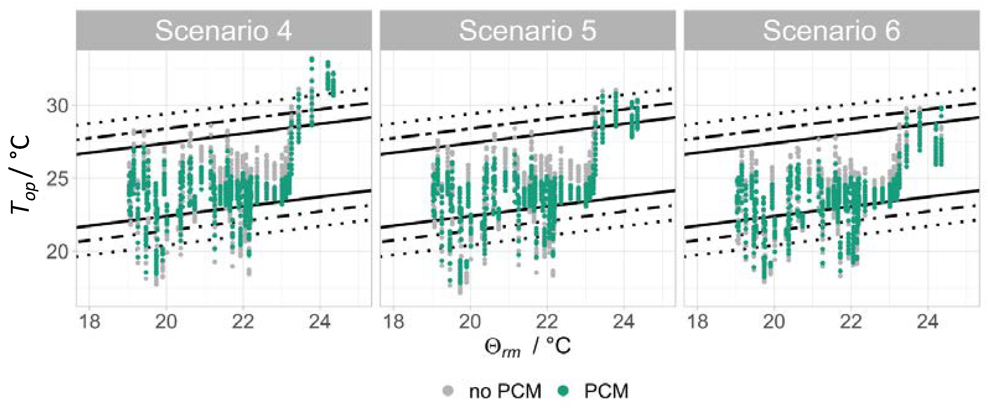
In respect of evaluating the overall comfort level of both rooms, comfort diagrams according to DIN EN 16798-1 were prepared. Comfort diagrams using adaptive temperature limits visualise the indoor temperature Top as a function of the running mean of the daily ambient temperature Tamb and show whether and how often Top exceeds or falls below defined comfort limits.
The running mean of ambient temperature Θrm was calculated according to Equation (2) [27]:
Θ r m = ( Θ e d 1 + 0.8 × Θ e d 2 + 0.6 × Θ e d 3 + 0.5 × Θ e d 4 + 0.4 × Θ e d 5 + 0.3 × Θ e d 6 + 0.2 × Θ e d 7 ) × 1 3.8
Here, Θed−i represents the daily mean of the measured ambient temperature on the i-th preceding day. For buildings without mechanical cooling, which the two case studies were, the standard applied three different adaptive comfort limits corresponding to high, medium and moderate thermal comfort demands.

3. Results

3.1. Office Room

Effect of mechanical night ventilation: Based on the results shown in Table 2, we considered an ACH value of 2 with temperature reductions of maximum 4.0 K and of 2.3 K on average to be the best mechanical night ventilation intensity, since the maximum temperature reduction was not increased, and the average temperature reduction was only slightly greater when the ACH was set to level 3. This is because a lower ACH value goes hand in hand with a lower energy demand, which is why we considered this level to be the optimum between the cooling effect and energy demand.
Improvement of thermal conditions through PCM: In all scenarios, the PCM was able to reduce the room temperature. Assuming a 100% capacity, the maximum and average temperature reductions due to the PCM in S1 were 1.22 K and 0.38 K, respectively, (cf., Table 3) during office hours (Monday–Friday, 9 a.m.–6 p.m.).
At 50% capacity, the temperature reductions were significantly lower at 0.69 K and 0.21 K. With increasingly better behaviour (S2 and S3), slightly different trends emerged for the different PCM capacities. While the PCM effect increased at 50% to 1.00 K and 0.35 K, respectively, they reached their maximum at 100% capacity in S1 and were below that in S2 and S3. Interestingly, there was no significant difference between the two PCM capacities in S3. One possible interpretation of these two opposing effects would be that by improving the behaviour of the users, the existing PCM was able to work better and improve the thermal conditions to some degree in the case of 50% capacity. Improved ventilation and shading management thus made it possible to further increase the temperature reduction achieved by PCMs and hence exert a positive influence on the thermal conditions in the room. For the 100% capacity on the other hand, one could get the impression that the better the user behaviour, the smaller the PCM’s effect. However, as mentioned above, we did not consider temperature reductions alone to be an appropriate measure of the effectiveness of a PCM application. A more precise assessment was made possible by the additional analysis of CDH, as the prevailing temperature level was also taken into account. This is because it made a difference to the users’ thermal comfort whether the temperature peaks above or below the comfort limit were reduced. Considering the CDH of different behavioural scenarios (Figure 9), it became obvious that, firstly, the PCM could reduce discomfort hours by 9–16% within the scenario of real behaviour. Moreover, improved user behaviour was also able to make an important additional contribution: improved shading and use of window reduced the CDH significantly by 71% and the PCM had an additional effect of a 22 to 28% reduction. These results suggest for both PCM capacities that the better the user behaviour, the greater the relative contribution of the PCM. However, when looking at the absolute number of CDH reduced by the PCM, it is evident that this was greatest in S1 and steadily decreased in S2 and S3. In addition, compared to S2, where improved shading and natural ventilation significantly reduced the discomfort time, the additional mechanical night ventilation caused a further reduction from 46 to 8 CDH.
The positive effect of improved user behaviour on thermal conditions is also apparent in the comfort diagrams (Figure 10). They show that the temperature level could be lowered through improved behaviour; while the mean Top during working hours in S1 was 25.7 °C, it dropped to 24.5 and 23.3 °C in S2 and S3, respectively. However, there were also quite low temperatures that were below the comfort boundaries. These were mainly morning hours after cold nights. Especially in S3, temperatures frequently fell below the comfort limits due to the implemented mechanical night ventilation. This strong cooling of the room could easily be prevented if it was perceived as uncomfortable by the users. The scenarios set 19 °C as the lower limit for the opening of the ventilation panel, and there was no cut-off temperature for the electric night ventilation. Consequently, in real use, severe cooling can be easily prevented by switching off the electric ventilation when the room temperatures are correspondingly low, and a cold night is coming. The comfort diagrams also confirm the comparatively low influence of the PCM in the office room. Temperatures without PCM were only slightly higher than those with PCM. Likewise, in S1, the somewhat more pronounced temperature-reducing effect of the 100% capacity PCM could be seen. In S2, however, this effect became very small and in S3 the difference in capacity no longer played a role. In S2, another effect of the PCM became apparent: the PCM not only served to prevent overheating, but also to reduce the excessive cooling of the room air through the stored and subsequent time-delayed release of heat. This could be clearly seen in S2 on days when the 50% variant achieved lower values than the than 100% variant.

3.2. Classroom

Improvement of thermal conditions through PCM: The maximum and average temperature drops due to PCM under the assumption of real user behaviour were 2.35 K and 0.94 K, respectively (Table 4), during the teaching period (Monday–Friday, 7 a.m.–5 p.m.). Looking at the other two scenarios, it became clear that by improving the behaviour of the users, the effect of the PCM on temperature reduction decreased until a 2.04 K maximum and 0.61 K mean temperature drop. However, the analysis of the CDH showed that, as in the other case study, improved behaviour could mitigate the conditions of thermal discomfort significantly. In addition, the relative contribution of the PCM increased slightly from 45% in S4 up to 52% in S6 (Figure 11). It became clear that window ventilation was of great importance. Slight improvements in comfort could also be achieved through improved shading, but ventilation had a considerably greater influence (cf. S5 and S6 in Figure 11).
The comfort diagrams of the different behaviour scenarios confirmed this finding (Figure 12): The temperatures outside the comfort limits of category III could be significantly reduced through better behaviour. The mean Top could also be reduced from 24.4 °C in scenario S4 to 24.1 and 23.5 °C (scenarios S5 and S6, respectively).
Even more frequently than in the other case study, the comfort limits were clearly and frequently undershot in the classroom, and ventilation intensified this effect. In contrast to the office, our measurement data also showed that the room occasionally cooled down considerably during real use, especially in the morning hours after cool nights. So, it is quite possible that the cooling in the morning in summer was deliberate and did not affect the subjective feeling of comfort of at least the teachers. This was because, as mentioned in the other case study, excessive night-time cooling can easily be prevented by leaving fewer windows open on cold nights. The comfort diagrams also visualize once again the stronger influence of the PCM in this room, recognizable by the smaller vertical spread of the PCM data points compared to those without PCM.

4. Discussion

4.1. Impact of PCM

Our simulation results revealed that the PCM still worked after more than a decade in operation and still had a positive impact on the thermal behaviour of the rooms. The analyses indicated that in both cases there was a decrease in the PCM capacity in the meantime in the range of up to 50%. Moreover, all the behavioural scenarios showed a temperature-reducing effect through the PCM during working hours. In the office room it was on average 0.2–0.4 K, and in the classroom, it reached 0.6–0.9 K, which was somewhat higher. Temperature peaks could also be significantly mitigated by the PCM. In the office, maximum temperature reductions of between 0.7–1.2 K and in the classroom of 2.0–2.4 K could be achieved, depending on the scenario. When measuring the discomfort time, it became clear that the PCM was able to reduce the uncomfortably warm time in the office room by 9 to 34%, whereas its effect in the classroom was considerably higher at a 45 to 52% reduction. However, in both buildings, the PCM was able to contribute to an improvement in thermal comfort in all scenarios.
The greater influence of the PCM in the classroom can be attributed to two factors: the construction of the buildings and the prevailing temperature level. While the office in the Sonnenschiff has a massive construction with thermally heavy ceilings and floors, the school building is a thermally lighter construction. The better buffering of temperature fluctuations by the thermal mass was also evident in the lower temperature amplitudes in the office compared to the classroom and in the fact that the temperatures rarely moved outside the limits of the comfort categories. This result was in line with the fact that PCMs can especially show their potential in light buildings and their influence is greater there than in thermally heavy buildings [9,47]. In addition, our results showed that this did not change substantially after more than a decade in operation. Another aspect for the different effects of the PCMs in the two buildings was probably the prevailing temperature level, which obviously favored the PCM operation in the classroom. In the office, temperatures were more often above the melting range of the PCM and therefore could not influence the thermal performance of the room, whereas in the classroom the PCM could be activated more often.

4.2. Influence of User Behaviour

The different behavioural scenarios showed that in addition to the PCM, the behavioural factor also had a major influence on comfort. It not only influenced thermal performance—which is sufficiently well known—but also the extent to which the PCM could unfold its temperature-balancing effect. Comparing the PCM effect of the different behavioural scenarios in relation to the mean and maximum temperature reductions, one could get the impression that better behaviour tended to mitigate the PCM effect (especially for the classroom, Table 4). However, these values gave no information about the level at which the temperature reduction took place. For instance, a temperature reduction from 28 to 26 °C is much more relevant and valuable to users than from 26 to 24 °C. Therefore, the CDH, which are a measure of time and extent of discomfort, more accurately quantify the PCM’s effect in our opinion. In addition, these showed that the relative proportion of the PCM’s effect grew due to improved behaviour, but not the absolute number of CDH.
Interestingly, however, it also turned out that the influence of the user’s behaviour on the average room temperature was different: In the office, better shading and window ventilation achieved a reduction of 1.2 °C, and electric night ventilation doubled this value to 2.4 °C. In the classroom, on the other hand, the reduction was only 0.9 °C overall. The reason for this is probably, on the one hand, the design of the behavioural scenarios and how "good" the behaviour already was in the basic scenarios. This would mean that the real behaviour in the classroom was already much closer to what we defined as good behaviour. On the other hand, in the office, the user’s behaviour was even further away compared to what we defined as better behaviour. Another cause is the electric night ventilation, as it is always more effective in terms of night-time regeneration than natural ventilation can be.
However, from our results, two aspects became visible, that (a) there was an interaction between the two factors of behaviour and PCM and (b) behaviour variations had a larger effect on thermal performance than the PCM had—which has already been mentioned in literature before [15,17,20]. Improved behaviour always led to an increase in the PCM effect measured in CDH in our simulations. Our results particularly confirmed the importance of night ventilation, which was in accordance with common operating instructions and scientific articles [18,48,49].
The effectiveness of the PCM under different behavioural scenarios, however, depended strongly on the prevailing temperature regime. If the room temperatures were often above the melting point of the PCM, which was then virtually switched it off, then improved behaviour in the form of ventilation, shading, etc., could reduce the temperatures to such an extent that the PCM could work again. If, on the other hand, the room temperatures were already within the working range of the PCM, the PCM’s effect did not increase as much with improved behaviour.
Due to the found interaction of behaviour and PCM effect, it is extremely important for future projects to implement realistic user behaviour in ex ante simulations, as already noted by Lamrani et al. [11]. Otherwise, the use of optimal behaviour can lead to an overestimation of the benefits and the already identified performance gap [16,18], which in practice leads to disappointment later. We also recommend for future simulation studies to use not only the mean and maximum temperature reductions as the evaluation variables, but also the time of discomfort (CDH), as this is a much more meaningful measure.

5. Conclusions

The aim of this study was to gain insights into the importance of user behaviour to the functioning of PCMs. We wanted to know to what extent there was room for optimization of PCM performance in real documented user behaviour.
To investigate this, we chose two buildings, namely a school and an office building, in which we monitored the indoor climate and behavioural parameters for several months during summer 2018. We then created a model for each of the spaces and used the measured data to calibrate and validate the models. The analysis of the behavioural data showed that there was room for improvement in terms of thermal conditions in both rooms. Thus, for both spaces, in addition to the baseline scenario, in which we had implemented the real documented behaviour, we created two scenarios, in each of which the behaviour of the users in terms of the application of the blinds, window ventilation and, for the office case, the usage of the existing electrical ventilation was improved.
Our main findings were:
  • The occupants did not behave optimally from a technical perspective. Windows were opened when it was too warm outside, blinds were not always closed when there was high irradiation and night ventilation by means of windows or electrical ventilation systems was not used consistently.
  • Simulations with different behavioural scenarios showed that the PCM still worked after more than a decade in operation and could positively influence the indoor climate in all the scenarios. However, our results suggested that there was a decrease in the capacity of the PCM in the meantime. The amount of degradation could only be roughly determined and was in the range of 0–50%. Despite the decrease in capacity, it was able to reduce the time of discomfort in the baseline scenarios by 9–45% and improved behaviour led to an increase in the PCM’s effect of 34–52%.
  • The improved behaviour itself also provided an improvement in thermal conditions. The effect of behaviour was also visibly greater than the effect attributable to the PCM; the average room temperatures could be reduced by 2.4 K (office) and 0.9 K (classroom) through better blind operation, more consistent window ventilation and, above all, the use of night ventilation (in the office). The same pattern was seen in the CDH.
  • The general temperature level also influenced the extent to which behaviour and PCM could have an impact. If the room temperatures were frequently above the melting range, the PCM could not work. If, on the other hand, the temperatures were more frequently within the melting range of the PCM, it was able to unfold its effect.
  • Our results confirmed that PCMs can show their strength better in light buildings than in thermally heavy ones.
Recommendations: Based on the study results, we were able to verify our hypothesis that user behaviour had a strong influence on the functionality of the PCM. We found that the better the behaviour from a technical perspective, the greater the relative contribution of the PCM. Therefore, we recommend that in future studies on the evaluation of PCMs and the planning of their use, realistic user behaviour should be integrated. Studies that only assume optimal user behaviour inevitably overestimate the realizable potential and raise user expectations of the PCM that can hardly be fulfilled later in operation and thus contribute to the aforementioned performance gap. Furthermore, it is of great importance to point out to the users the great influence they have on the functionality of the PCM system through their behaviour and to give them some advice on how to operate it in the best possible way. The supply of systematic information could help improve users’ awareness of behavioural choices and thus promote the proper functioning of PCM applications. This includes consistent shading when the facade is exposed to direct sunlight, window ventilation should only take place when the room temperatures are above the outside temperatures, and—probably the most important aspect—the implementation of consistent night ventilation. Especially with passive PCM applications, this is of elementary importance to ensure the regeneration of the PCM by releasing the absorbed heat and allowing the paraffin wax to return to its solid state.
Another aspect that we would like to emphasize in conclusion is that it was also possible to deduce from our investigations how important the choice of the respective analysed period is. If only individual days or a few weeks are used for evaluation, the results can easily be biased. We therefore recommend always including the entire warm season in the analysis, if possible.

Author Contributions

T.O.: conceptualization, methodology, investigation, data curation, software, formal analysis, writing—original draft, visualization, project administration; S.G. (Sebastian Gölz): conceptualization, funding acquisition, supervision, writing—review & editing; T.H.: conceptualization, data curation, funding acquisition, investigation, writing—review & editing, project administration; S.G. (Stefan Gschwander): funding acquisition, supervision, writing—review & editing; A.W.: supervision, writing—review & editing. All authors have read and agreed to the published version of the manuscript.

Funding

The authors are grateful to the Federal Ministry for Economic Affairs and Energy (funding code 03ET1443A) for supporting this research financially. Apart from the financing, the donor had no further influence on the present study, its implementation and design.

Data Availability Statement

Data available upon request from the corresponding author.

Acknowledgments

We would like to thank Juanita Solano Guzmán who actively supported us in creating one of the simulation models.

Conflicts of Interest

The authors declare no conflict of interest.

Nomenclature

PCMPhase change material
DSCDifferential scanning calorimeter
DINDeutsches Institut für Normung (German Institute for Standardization)
ENEuropean standard
CDHCooling degree hours
RMSERoot mean square error
Coefficient of determination
U-ValueThermal transmittance
ACHAir change per hours
TopOperative room temperature
TambAmbient air temperature
TlimLimit of comfort
NNumber of points
ΘrmRunning mean of ambient temperature
Θer_iDaily running mean of ambient temperature

Appendix A

Figure A1. Data input for PCM material in EP following the hysteresis model [19]. Sources: density values [50], specific heat values and thermal conductivities [51]. All other values were obtained from own measurements.
Buildings 12 01797 g0a1
Table A1. Thermal properties of construction elements: office room [17]. Values obtained from Ubakus online calculator [52].
ConstructionMaterialThicknessConductivitySpecific HeatDensity
[mm][W/(m·K)][J/(kg·K)][kg/m3]
Ceiling & floorBeton external252.0009502400
[U = 0.19 W/(m2·K)]Cement screed601.40010002000
Styrofoam2000.040150020
Beton internal252.0009502400
Internal wallSmartboard150.250960680
[U = 0.75 W/(m2·K)]Blown-in insulation450.0432200105
Beton102.0009502400
Smartboard150.250960680
WindowsGlass60.7608402500
[U = 0.71 W/(m2·K)]Air160.00010001.2
Glass60.7608402500
Air160.00010001.2
Glass60.7608402500
Post and beam constructionSolid wood3400.1101700480
[U = 0.31 W/(m2·K)]
External wallVacuum insulation500.007800200
[U = 0.14 W/(m2·K)]Beton 1002.0009502400
DoorWooden door250.1902390700
[U = 2.70 W/(m2·K)]
Table A2. Thermal properties of construction elements: classroom. Values obtained from Ubakus online calculator [52].
ConstructionMaterialThicknessConductivitySpecific HeatDensity
[mm][W/(m·K)][J/(kg·K)][kg/m3]
CeilingElastomer sealing sheet1.50.17010001400
[U = 0.28 W/(m2·K)]Insulation board500.0451300110
OSB board190.1301700650
Mineral wool1000.0351700650
Steel girder100 50.0001000285
Sealing foil0.250.17010001100
Knauf fire protection GKF180.2301100800
Knauf GKF12.50.2301100800
Air layer1721.07510001.2
Smartboard150.250960680
FloorLinoleum50.17014001200
[U = 0.20 W/(m2·K)]OSB board190.1301700650
Gypsum plasterboard150.35011001150
OSB board220.1301700650
Sealing foil0.250.17010001100
Mineral wool1400.0351700650
Steel girder15050.0001000285
Trapezoidal sheet110.0001000100
OSB board100.1301700650
Mineral wool1000.0351700650
Steel girder10050.0001000285
Vapour barrier0.250.17010001100
Knauf fire protection GKF180.2301100800
Knauf fire protection GKF150.2301100800
Air layer1721.07510001.2
Smartboard150.250960680
Facade wallSynthetic resin plaster30.70010001200
[U = 0.24 W/(m2·K)]Styrofoam600.04150020
Gypsum plasterboard150.35011001150
Seal foil0.250.17010001100
Mineral wool1000.03583020
Steel girder10050.0001000285
Sealing foil0.250.17010001100
Air layer1350.75010001.2
Steel girder7550.0001000285
Air layer750.75010001.2
Knauf GKF12.50.2301100800
Smartboard150.250960680
Knauf GKF12.50.2301100800
Chalkboard and rear wallKnauf GKF12.50.2301100800
[U = 0.34 W/(m2·K)]Smartboard150.250960680
Knauf GKF12.50.2301100800
Seal foil0.250.17010001100
Air layer7.50.01010001.2
Steel girder7550.0001000285
Mineral wool600.03583020
Air layer7.50.01010001.2
Steel girder7550.0001000285
Mineral wool600.03583020
Air layer750.75010001.2
Seal foil0.250.17010001100
Knauf GKF12.50.2301100800
Corridor wallKnauf GKF12.50.2301100800
[U = 0.53 W/(m2·K)]Smartboard150.250960680
Knauf GKF12.50.2301100800
Air layer7.50.01010001.2
Mineral wool600.03583020
Steel girder7550.0001000285
Air layer7.50.01010001.2
Knauf GKF12.50.2301100800
Sink wallKnauf GKF12.50.2301100800
[U = 0.46 W/(m2·K)]Smartboard150.250960680
Knauf GKF12.50.2301100800
Steel girder7550.0001000285
Air layer2751.52810001.2
Seal foil0.250.17010001100
Air layer750.75010001.2
Mineral wool600.03583020
Steel girder7550.0001000285
Air layer7.50.01010001.2
Seal foil0.250.17010001100
Knauf GKF12.50.2301100800
Smartboard150.250960680
Knauf GKF12.50.2301100800
WindowsGlass60.7608402500
[U = 0.71 W/(m2·K)]Air160.00010001.2
Glas60.7608402500
Air160.00010001.2
Glass60.7608402500
DoorWooden door500.131700750
[U = 1.55 W/(m2·K)]
Figure A2. Drawing of the office floor in the Sonnenschiff. Red numbers in the red circles designate the partitions equipped with PCM plasterboard. The red box indicates the analysed room [17].
Buildings 12 01797 g0a2
Figure A3. Drawing of the second floor of Nordstadt Lycee. The red box indicates the analysed room.
Buildings 12 01797 g0a3

References

  1. Mavrigiannaki, A.; Ampatzi, E. Latent heat storage in building elements: A systematic review on properties and contextual performance factors. Renew. Sustain. Energy Rev. 2016, 60, 852–866. [Google Scholar] [CrossRef] [Green Version]
  2. AL-Saadi, S.N.; Zhai, Z. Modeling phase change materials embedded in building enclosure: A review. Renew. Sustain. Energy Rev. 2013, 21, 659–673. [Google Scholar]
  3. Khudhair, A.M.; Farid, M.M. A review on energy conservation in building applications with thermal storage by latent heat using phase change materials. Energy Convers. Manag. 2004, 45, 263–275. [Google Scholar] [CrossRef]
  4. James, B.; Delaney, P. Phase Change Materials: Are They Part of Our Energy Efficient Future? In Proceedings of the 2012 ACEEE Summer Study on Energy Efficiency in Build, Pacific Grove, CA, USA, 12–17 August 2012; pp. 160–172. [Google Scholar]
  5. Ascione, F.; Bianco, N.; de Masi, R.F.; de’ Rossi, F.; Vanoli, G.P. Energy refurbishment of existing buildings through the use of phase change materials: Energy savings and indoor comfort in the cooling season. Appl. Energy 2014, 113, 990–1007. [Google Scholar] [CrossRef]
  6. Barreneche, C.; Navarro, L.; de Gracia, A.; Fernández, A.I.; Cabeza, L.F. In situ thermal and acoustic performance and environmental impact of the introduction of a shape-stabilized PCM layer for building applications. Renew. Energy 2016, 85, 281–286. [Google Scholar] [CrossRef] [Green Version]
  7. Li, D.; Zheng, Y.; Liu, C.; Wu, G. Numerical analysis on thermal performance of roof contained PCM of a single residential building. Energy Convers. Manag. 2015, 100, 147–156. [Google Scholar] [CrossRef]
  8. Jaworski, M.; Łapka, P.; Furmański, P. Numerical modelling and experimental studies of thermal behaviour of building integrated thermal energy storage unit in a form of a ceiling panel. Appl. Energy 2014, 113, 548–557. [Google Scholar] [CrossRef]
  9. Karim, L.; Barbeon, F.; Gegout, P.; Bontemps, A.; Royon, L. New phase-change material components for thermal management of the light weight envelope of buildings. Energy Build. 2014, 68, 703–706. [Google Scholar] [CrossRef]
  10. Royon, L.; Karim, L.; Bontemps, A. Optimization of PCM embedded in a floor panel developed for thermal management of the lightweight envelope of buildings. Energy Build. 2014, 82, 385–390. [Google Scholar] [CrossRef]
  11. Lamrani, B.; Johannes, K.; Kuznik, F. Phase change materials integrated into building walls: An updated review. Renew. Sustain. Energy Rev. 2021, 140, 110751. [Google Scholar] [CrossRef]
  12. Schakib-Ekbatan, K.; Çakıcı, F.Z.; Schweiker, M.; Wagner, A. Does the occupant behavior match the energy concept of the building?—Analysis of a German naturally ventilated office building. Build. Environ. 2015, 84, 142–150. [Google Scholar] [CrossRef]
  13. Fabi, V.; Andersen, R.V.; Corgnati, S.; Olesen, B.W. Occupants’ window opening behaviour: A literature review of factors influencing occupant behaviour and models. Build. Environ. 2012, 58, 188–198. [Google Scholar] [CrossRef]
  14. Alam, M.; Jamil, H.; Sanjayan, J.; Wilson, J. Energy saving potential of phase change materials in major Australian cities. Energy Build. 2014, 78, 192–201. [Google Scholar] [CrossRef]
  15. Jamil, H.; Alam, M.; Sanjayan, J.; Wilson, J. Investigation of PCM as retrofitting option to enhance occupant thermal comfort in a modern residential building. Energy Build. 2016, 133, 217–229. [Google Scholar] [CrossRef]
  16. Alam, M.; Zou, P.X.; Sanjayan, J.; Ramakrishnan, S. Energy saving performance assessment and lessons learned from the operation of an active phase change materials system in a multi-storey building in Melbourne. Appl. Energy 2019, 238, 1582–1595. [Google Scholar] [CrossRef]
  17. Obergfell, T.; Solano Guzmán, J.; Haussmann, T.; Gschwander, S.; Wagner, A. Long-term functionality of a passive phase-change materials building application after more than a decade of operation. Energy Build. 2021, 249, 111213. [Google Scholar] [CrossRef]
  18. Wan Mohd Nazi, W.I.; Wang, Y.; Chen, H.; Zhang, X.; Roskilly, T. Passive Cooling Using Phase Change Material and Insulation for High-rise Office Building in Tropical Climate. Energy Procedia 2017, 142, 2295–2302. [Google Scholar] [CrossRef]
  19. US Department of Energy. EnergyPlus™ Version 9.2.0 Documentation: Input Output Reference. 2019. Available online: https://energyplus.net/documentation (accessed on 20 June 2020).
  20. Sage-Lauck, J.S.; Sailor, D.J. Evaluation of phase change materials for improving thermal comfort in a super-insulated residential building. Energy Build. 2014, 79, 32–40. [Google Scholar] [CrossRef]
  21. Oebbeke, A. Latentwärmespeicher Micronal PCM der BASF Auch in Gipsbauplatten. 2005. Available online: https://www.baulinks.de/webplugin/2005/1324.php4 (accessed on 25 June 2022).
  22. Cellat, K.; Beyhan, B.; Konuklu, Y.; Dündar, C.; Karahan, O.; Güngör, C.; Paksoy, H. 2 years of monitoring results from passive solar energy storage in test cabins with phase change materials. Sol. Energy 2020, 200, 29–36. [Google Scholar] [CrossRef]
  23. Cabeza, L.F.; Navarro, L.; Pisello, A.L.; Olivieri, L.; Bartolomé, C.; Sánchez, J.; Álvarez, S.; Tenorio, J.A. Behaviour of a concrete wall containing micro-encapsulated PCM after a decade of its construction. Sol. Energy 2020, 200, 108–113. [Google Scholar] [CrossRef]
  24. BASF SE. Company Website. 2020. Available online: https://www.basf.com/global/de.html (accessed on 20 June 2022).
  25. Disch, R.; Schüle, R.; Tebel-Haas, S. Innovative Energiefassade für das Sonnenschiff der Solarsiedlung Freiburg: Final Report DBU Research Project. 2009. Available online: https://docplayer.org/64623896-Innovative-energiefassade-fuer-das-sonnenschiff-der-solarsiedlung-freiburg.html (accessed on 20 June 2022).
  26. Rolf Disch SolarArchitektur. 2022. Available online: http://www.rolfdisch.de/media-de/bildarchiv/ (accessed on 20 June 2022).
  27. DIN Deutsches Institut für Normung e.V. Teil1: Eingangsparameter für das Innenraumklima zur Auslegung und Bewertung der Energieeffizienz von Gebäuden bezüglich Raumluftqualität, Temperatur, Licht und Akustik. In DIN EN 16798-1: Energetische Bewertung von Gebäuden: Lüftung von Gebäuden; Beuth Verlag GmbH: Berlin, Germany, 2021. [Google Scholar]
  28. Ross, S.M. Chapter 12 linear regression. In Introductory Statistics, 3rd ed.; Ross, S.M., Ed.; Academic Press: Boston, MA, USA, 2010; pp. 537–604. [Google Scholar]
  29. Moore, D.; Notz, W.I.; Fligner, M.A. (Eds.) The Basic Practice of Statistics, 6th ed.; W. H. Freeman and Company: New York, NY, USA, 2013. [Google Scholar]
  30. Halimov, A.; Lauster, M.; Müller, D. Development and Validation of PCM Models Integrated Into the High-order Building Model of Modelica Library—Aixli. In Proceedings of the 16th IBPSA Conference, Rome, Italy, 2–4 September 2019; pp. 4698–4705. [Google Scholar]
  31. Al-Janabi, A.; Kavgic, M. Application and sensitivity analysis of the phase change material hysteresis method in EnergyPlus: A case study. Appl. Therm. Eng. 2019, 162, 114222. [Google Scholar] [CrossRef]
  32. DesignBuilder Software Ltd. Phase Change Material—Hysteresis. 2020. Available online: https://designbuilder.co.uk/helpv6.0/Content/PhaseChangeMaterialHysteresis.htm (accessed on 20 June 2022).
  33. Big Ladder Software. Conduction Finite Difference Solution Algorithm. 2018. Available online: https://bigladdersoftware.com/epx/docs/9-0/engineering-reference/conduction-finite-difference-solution.html (accessed on 20 June 2022).
  34. Alam, M.; Sanjayan, J.; Zou, P.X.; Ramakrishnan, S.; Wilson, J. A Comparative Study on the Effectiveness of Passive and Free Cooling Application Methods of Phase Change Materials for Energy Efficient Retrofitting in Residential Buildings. Procedia Eng. 2017, 180, 993–1002. [Google Scholar] [CrossRef]
  35. Long, X.; Zhang, W.; Li, Y.; Zheng, L. Thermal performance improvement of lightweight buildings integrated with phase change material: An experimental and simulation study. Adv. Mech. Eng. 2017, 9, 1687814017702082. [Google Scholar] [CrossRef] [Green Version]
  36. Ozdenefe, M.; Dewsbury, J. Thermal performance of a typical residential Cyprus building with phase change materials. Build. Serv. Eng. Res. Technol. 2015, 37, 85–102. [Google Scholar] [CrossRef] [Green Version]
  37. Devaux, P.; Farid, M.M. Benefits of PCM underfloor heating with PCM wallboards for space heating in winter. Appl. Energy 2017, 191, 593–602. [Google Scholar] [CrossRef]
  38. Saffari, M.; de Gracia, A.; Ushak, S.; Cabeza, L.F. Economic impact of integrating PCM as passive system in buildings using Fanger comfort model. Energy Build. 2016, 112, 159–172. [Google Scholar] [CrossRef] [Green Version]
  39. Lei, J.; Yang, J.; Yang, E.-H. Energy performance of building envelopes integrated with phase change materials for cooling load reduction in tropical Singapore. Appl. Energy 2016, 162, 207–217. [Google Scholar] [CrossRef]
  40. Soares, N.; Reinhart, C.F.; Hajiah, A. Simulation-based analysis of the use of PCM-wallboards to reduce cooling energy demand and peak-loads in low-rise residential heavyweight buildings in Kuwait. Build. Simul. 2017, 10, 481–495. [Google Scholar] [CrossRef]
  41. Auzeby, M.; Wei, S.; Underwood, C.; Tindall, J.; Chen, C.; Ling, H.; Buswell, R. Effectiveness of Using Phase Change Materials on Reducing Summer Overheating Issues in UK Residential Buildings with Identification of Influential Factors. Energies 2016, 9, 605. [Google Scholar] [CrossRef] [Green Version]
  42. Jiao, F.; Xu, P. Simulation and Feasibility Analysis of PCM Based Passive Cooling Technique in Residential House. Procedia Eng. 2015, 121, 1969–1976. [Google Scholar] [CrossRef]
  43. Medved, S.; Arkar, C. Correlation between the local climate and the free-cooling potential of latent heat storage. Energy Build. 2008, 40, 429–437. [Google Scholar] [CrossRef]
  44. Assawamartbunlue, K. An Investigation of Cooling and Heating Degree-Hours in Thailand. J. Clean Energy Technol. 2013, 1, 87–90. [Google Scholar] [CrossRef] [Green Version]
  45. Evola, G.; Marletta, L.; Sicurella, F. A methodology for investigating the effectiveness of PCM wallboards for summer thermal comfort in buildings. Build. Environ. 2013, 59, 517–527. [Google Scholar] [CrossRef]
  46. DIN Deutsches Institut für Normung e.V. DIN 4108-2. Wärmeschutz und Energie-Einsparung in Gebäuden: Teil 2: Mindestanforderungen an den Wärmeschutz; Beuth Verlag GmbH: Berlin, Germany, 2013. [Google Scholar]
  47. Akeiber, H.; Nejat, P.; Majid, M.Z.A.; Wahid, M.A.; Jomehzadeh, F.; Zeynali Famileh, I.; Calautit, J.K.; Hughes, B.R.; Zaki, S.A. A review on phase change material (PCM) for sustainable passive cooling in building envelopes. Renew. Sustain. Energy Rev. 2016, 60, 1470–1497. [Google Scholar] [CrossRef]
  48. Liu, X.; Zhou, Y.; Zhang, G. Numerical study on cooling performance of a ventilated Trombe wall with phase change materials. Build. Simul. 2018, 11, 677–694. [Google Scholar] [CrossRef]
  49. Soudian, S.; Berardi, U. Assessing the effect of night ventilation on PCM performance in high-rise residential buildings. J. Build. Phys. 2019, 43, 229–249. [Google Scholar] [CrossRef]
  50. BASF SE. Product Overview: Polymer Dispersions, Powders and Additives for Sealants, Flooring Adhesives and New Building Materials, Ludwigshafen, Germany. 2011. Available online: https://dokumen.tips/documents/polymer-dispersions-powders-and-additives-for-overview-polymer-dispersions.html?page=1 (accessed on 3 March 2021).
  51. Navarro, L.; Solé, A.; Martín, M.; Barreneche, C.; Olivieri, L.; Tenorio, J.A.; Cabeza, L.F. Benchmarking of useful phase change materials for a building application. Energy Build. 2019, 182, 45–50. [Google Scholar] [CrossRef]
  52. Ubakus—der Abakus für den U-Wert, “U-Wert-Rechner”. 2020. Available online: https://www.ubakus.de/der-abakus-fuer-den-u-wert/ (accessed on 20 June 2022).
Figure 1. Process of model creation, PCM capacity determination and model implementation.
Buildings 12 01797 g001
Figure 2. “Western façade of the Sonnenschiff building in Freiburg, Southern Germany. The yellow-coloured marking indicates the part of the building where the room in question was located” [17,26].
Buildings 12 01797 g002
Figure 3. (a) Outer cover of the ventilation panel. (b) Wall-integrated cross-flow heat exchanger next to open ventilation panel [26].
Buildings 12 01797 g003
Figure 4. Left: View of the east façade of the school building. The examined room is marked in orange. Right: Interior view of the window front. The right wings of the windows can be opened, and permanent sun and rain protection is installed in front of them [Fraunhofer ISE].
Buildings 12 01797 g004
Figure 5. Model geometry of PCMroom in the Sonnenschiff and its surroundings in SketchUp. The front and upper shading objects represent the protection panel at the façade and the upper floor balcony, respectively. Window façade oriented towards east (92°) [Fraunhofer ISE].
Buildings 12 01797 g005
Figure 6. Model geometry of the analysed classroom (right room) generated in SketchUp. Window façade oriented towards east (78°) [Fraunhofer ISE].
Buildings 12 01797 g006
Figure 7. View into the investigated office room with highlighted window and ventilation panel [Fraunhofer ISE].
Buildings 12 01797 g007
Figure 8. Validation of both models. Simulation results with and without PCM are shown for comparison reasons, respectively.
Buildings 12 01797 g008
Figure 9. Effect of PCM on periods of discomfort within office room from July through September.
Buildings 12 01797 g009
Figure 10. Comfort diagrams with simulated Top of the three different behavioural scenarios for office room. Black lines indicate different comfort categories: solid = Category I—high standard, dot-dashed = category II—middle standard, dotted = category III—moderate standard.
Buildings 12 01797 g010
Figure 11. Effect of PCM on periods of thermal discomfort from June through September.
Buildings 12 01797 g011
Figure 12. Comfort diagrams with simulated Top of the three different behavioural scenarios for classroom. Black lines indicate different comfort categories: solid = Category I—high standard, dot-dashed = category II—middle standard, dotted = category III—moderate standard.
Buildings 12 01797 g012
Table 1. Goodness-of-fit measures of the PCM capacity variations for the two case studies. Bold font marks the best-fitting variants.
PCM Capacity [%]Office RoomClassroom
R2RMSE [K]R2RMSE [K]
1000.660.600.630.88
750.650.540.640.78
500.650.520.620.81
250.640.530.630.90
00.630.560.641.08
Table 2. Influence of different intensities of night ventilation on room temperature. Temperature reductions compared to simulation without night ventilation are given.
Night Ventilation
[ACH]
Max. Temperature
Reduction [K]
Mean Temperature
Reduction [K]
13.81.8
24.02.3
34.02.6
Table 3. Simulation results of different behavioural scenarios and influence of PCM for the office room. Temperature reductions indicated are due to PCM scenario (+) compared to scenario without PCM (−).
ScenarioPCMPCM
Capacity [%]
Natural Ventilation & ShadingMechanical Night VentilationMax. Temperature
Reduction by PCM [K]
Mean Temperature Reduction by PCM [K]
S1+/−50RealReal0.690.21
1001.220.38
S2+/−50ImprovedReal0.660.26
1000.940.31
S3+/−50ImprovedImproved1.000.35
1001.010.35
Table 4. Simulation results of different behavioural scenarios and influence of PCM for the classroom from June through September. Temperature reductions indicated are due to PCM scenario (+) compared to scenario without PCM (−), respectively.
ScenarioPCMShadingVentilationMax. Temperature Reduction by PCM [K]Mean Temperature Reduction by PCM [K]
4+/−RealReal2.350.94
5+/−ImprovedReal2.240.87
6+/−ImprovedImproved2.150.61
Publisher’s Note: MDPI stays neutral with regard to jurisdictional claims in published maps and institutional affiliations.