Article

Optimization of the Curved Metal Damper to Improve Structural Energy Dissipation Capacity

by
Young-Chan Kim
1,
Seyed Javad Mortazavi
2,
Alireza Farzampour
3,
Jong-Wan Hu
1,2,*,
Iman Mansouri
4 and
Paul Oluwaseun Awoyera
5
1
Incheon Disaster Prevention Research Center, Incheon National University, Incheon 22012, Korea
2
Department of Civil and Environmental Engineering, Incheon National University, Incheon 22012, Korea
3
Department of Civil and Environmental Engineering, Virginia Tech, Blacksburg, VA 24061, USA
4
Department of Civil Engineering, Birjand University of Technology, Birjand 97175-569, Iran
5
Department of Civil Engineering, Covenant University, Ota 112233, Nigeria
*
Author to whom correspondence should be addressed.
Buildings 2022, 12(1), 67; https://doi.org/10.3390/buildings12010067
Submission received: 11 November 2021 / Revised: 25 December 2021 / Accepted: 31 December 2021 / Published: 11 January 2022
(This article belongs to the Section Building Energy, Physics, Environment, and Systems)

Abstract

:
Structural curved metal dampers are implemented in various applications to mitigate the damages at a specific area efficiently. A stable and saturated hysteretic behavior for the in-plane direction is dependent on the shape of a curved-shaped damper. However, it has been experimentally shown that the hysteretic behavior in the conventional curved-shaped damper is unstable, mainly as a result of bi-directional deformations. Therefore, it is necessary to conduct shape optimization for curved dampers to enhance their hysteretic behavior and energy dissipation capability. In this study, the finite element (FE) model built in ABAQUS, is utilized to obtain optimal shape for the curved-shaped damper. The effectiveness of the model is checked by comparisons of the FE model and experimental results. The parameters for the optimization include the curved length and shape of the damper, and the improved approach is conducted by investigating the curved sections. In addition, the design parameters are represented by B-spline curves (to ensure enhanced system performance), regression analysis is implemented to derive optimization formulations considering energy dissipation, constitutive material model, and cumulative plastic strain. Results determine that the energy dissipation capacity of the curved steel damper could be improved by 32% using shape optimization techniques compared to the conventional dampers. Ultimately, the study proposes simple optimal shapes for further implementations in practical designs.

1. Introduction

In recent decades, the enhancement of structural resistance to seismic load inducing significant damages has been achieved by using passive energy dissipation (PED), which also relatively reduced the initial non-structural damages. The PED, operating as structural fuses, concentrates the damages in a specific part of the structures, which keeps the primary structure in an elastic state [1]. The use of the structural fuse has shown several benefits. One of the major benefits of damper usage is the component’s replaceability after an event occurred; thus, the repair works are conducted effectively without affecting the structural functionality [2,3,4,5,6,7,8,9].
The flexural yielding mechanism was originally addressed by the use of metallic fuse in various applications (e.g., Added Damping and Stiffness [10]). An added damping and stiffness showed in Figure 1 consisting of X-shaped steel plates acting as bracing systems. For this configuration, yielding is only possible across the entire device length under severe loads causing double curvature inelastic deformations [11].
Metallic fuses are extensively applied to serve as working mechanisms: flexural, axial, and shear yielding [13,14,15,16,17]. The shear panel fuse is made of a steel plate shear yielding mechanism, and it is mostly used for bracing hysteretic damping devices. An example of this system is presented in Figure 1. Several previous studies related to the use of steel plate shear walls and link beams have shown that the steel shear mechanism exhibits high strength and stiffness [18,19,20,21]. This mechanism demonstrates severe out-of-plane buckling behavior, which is a result of thin plate geometry, resulting in a reduction of hysteresis pinching, low ductility, and shear force. Procedures could be ascertained by either having cut-outs into a thin plate or adding stiffeners to the boundary of plates [11].
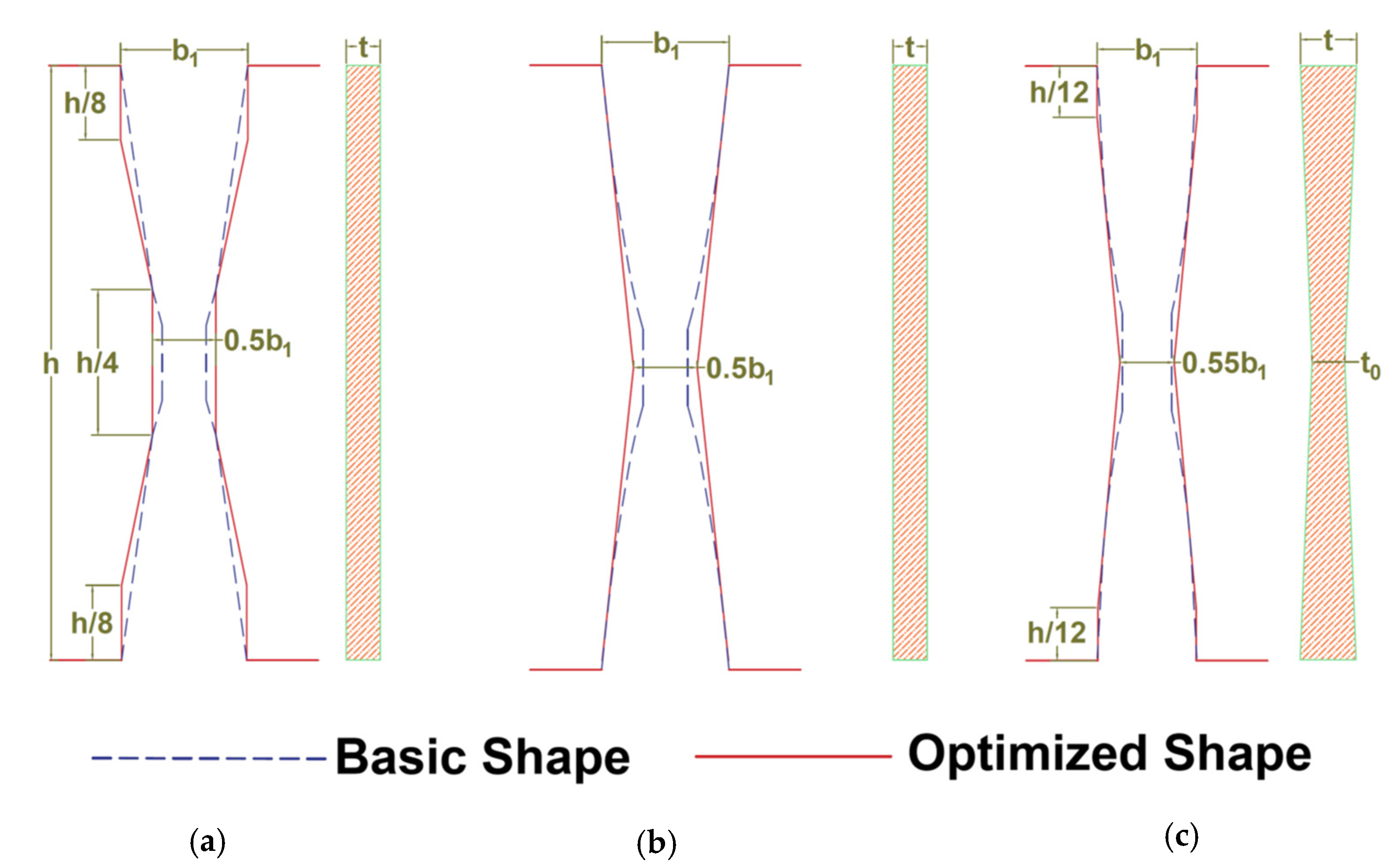
The cyclic behavior of uniform and non-uniform steel stripe dampers has been studied previously [22,23,24,25]. Figure 2 represent various damper shapes, which include (a) tapered strip, (b) dumbbell-shaped strip, and (c) hourglass-shaped strip. Test results indicate that the damage was not concentrated at the ends causing crack propagations compared to the case of the uniform sample [22]. Using appropriate design geometries for steel dampers could improve the cumulative ductility by 1.13–1.75, and energy dissipation by 1.27–2.36 [22] according to previous studies.
Iso-geometric analysis (IGA) has been identified as effective for modeling complex acoustic domain geometries and ensuring the accuracy of the model over the optimization phase [26]. For this approach, CAD geometries and the unknown variables are defined by using the spline basis functions. B-Splines and Non-Uniform Rational B-Splines (NURBs) are among the most commonly used spines [27]. It is noted that compared with the standard FE technique, the IGA method exhibits higher accuracy as a result of exact geometry evaluations, and higher basis function continuity [28,29]. In addition, computational errors could be reduced by using this approach refining the NURBs and ensuring a higher rate of solution approximations, and continuity [27,30].
Advancement in computer technology has aided numerous optimization algorithms related to structural optimization [31]. Algorithms such as the simulated annealing (SA), genetic algorithm (GA), and multi-level or multi-disciplinary optimization techniques have been developed previously for improving the low cycle fatigue behavior of the steel links [32,33,34,35,36]. In this study, the shape optimization approach using the SA method for enhancement of low cycle fatigue behavior steel shear panel dampers (SSPDs) is used for optimization purposes.
This research paper consists of two phases. The first phase is optimization analysis, and the second phase is FEM analysis. These phases were connected to each other. In the optimization phase, IGA analysis is carried out and the isoparametric formulation is applied in the FEM phase. To clarify this point, it was added to the text of the article. In this study, the finite element (FE) model developed in ABAQUS, is utilized to obtain optimal shape for the curved-shaped damper. The shape optimization techniques are implemented to improve the steel damper energy dissipation and the effectiveness of the model is compared with previous initial models.

2. B-Spline Basis Functions

By using the B-splines in parametric space, a non-uniform rational B-spline function (NURBS) was derived based on Equations (1) and (2) [27]:
N i , 0 ( ξ ) = {             1 ,           ξ i     ξ     ξ i + 1 0 ,           otherwise    
and for 1 ≤ p.
N i , p ( ξ ) = ξ   -   ξ i ξ i + p -   ξ i + 1 N i , p - 1 ( ξ ) + ξ i + p + 1 -   ξ ξ i + p + 1 -   ξ i + 1 N i + 1 , p - 1 ( ξ )
For which, the basis function for NURBS is given by Equation (3):
R i , p ( ξ ) = N i , p ( ξ ) w i i = 1 n N i , p ( ξ ) w i
where wi = ith weight.
Based on control points Bi, the NURBS curve was parameterized according to Equation (4):
C ( ξ ) = i = 1 n R i , p ( ζ ) B i
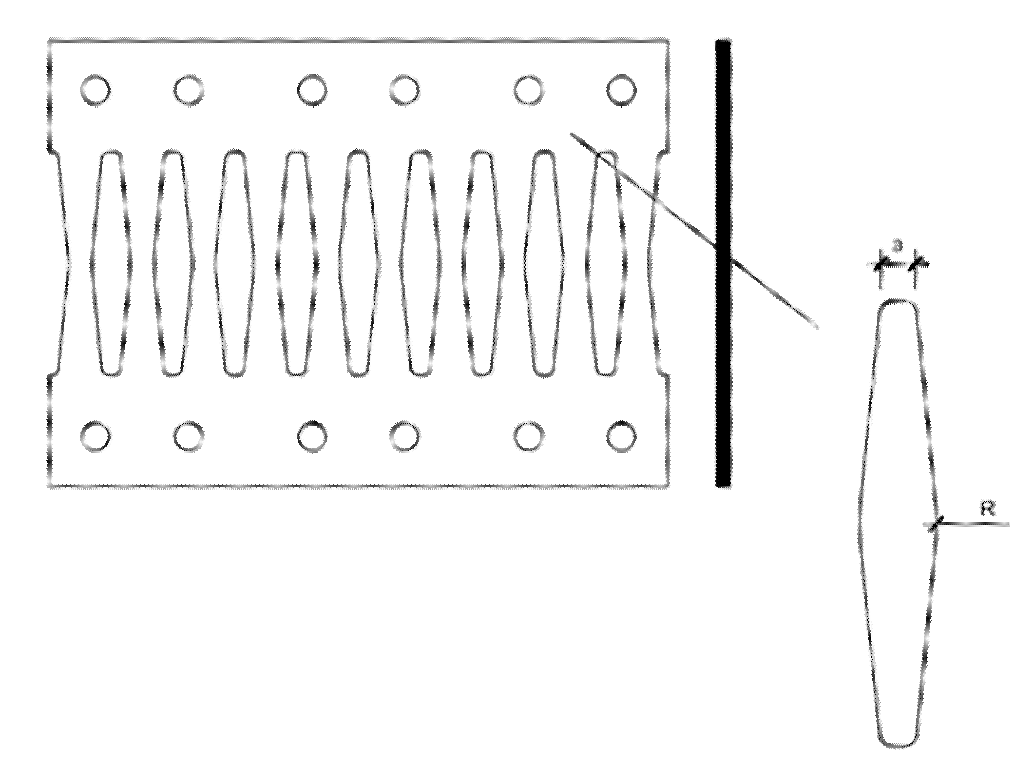
To ensure an effective steel shear panel dampers behavior, both end lengths and the middle section must be properly monitored. This implies that both end lengths and middle sections are among the most main influential dimensions for a typical steel damper. Thus, these dimensions are represented as the main design variables for the optimization process in this study (see Figure 1). To ensure effective energy dissipation and deformation ability of the steel shear panel dampers during cyclic loading, the optimization is performed based on maximizing the dissipated energy for plastic deformations (Ed) over the maximum equivalent plastic strain (PEEQmax) which is determined as the optimization objective function. The objective function for the steel shear panel damper shape optimization problem is defined as indicated in Equation (5) [3].
Find :   X = { a , b } Maximize   : F ( X ) = E d PEEQ max

3. Shape Optimization Based on Whale Optimization Algorithm

The metal curved damper is known to perform effectively based on two factors: the middle section (R) and the length of the damper end section (a) which were previously shown that as major parameters affecting the effective performance (see Figure 3).
In this approach, humpback whales’ social behavior was used for the whale optimization algorithm (WOA) development [37]. The algorithm is proposed by [38], after adopting the bubble-net hunting procedures. The WOA algorithm has been mainly used for continuous function optimization problems since it was proposed because it is easy in principle, operation, and implementation, and it is superior to other optimization algorithms in terms of solution accuracy and algorithm stability. In detail, it is mainly applied to optimization techniques in applied mathematics and civil engineering and skeletal structure design in construction engineering [39]. The principle of WOA is based on the preference of humpback whales to hunt a krill school or small fish around the water surface. This is achieved by causing a series of bubbles along a circle. It is noted that a whale in this algorithm corresponds to one feasible solution and the prey refers to the optimal solution. The targeted prey is encircled by the humpback whales simultaneously within a shrinking mechanism and through a spiral-shaped route. Therefore, each whale is assumed to select either the shrinking mechanism or the spiral-shaped approach to main its position by the probability of 50% [37] which is summarized in Equation (6).
X ( t + 1 ) = { X * ( t ) - A · D              if  p < 0.5 D · e b l · cos ( 2 π l ) + X * ( t )                if  p 0.5
where X(t+1) denotes updated next iteration (t + 1) position and p is a random number in [0, 1], 𝑋(𝑡) is the best solution obtained so far, 𝐴 is a random value greater than 1 or less than −1 to force each search agent (whale) to move, respectively, toward or far away from a reference whale, D′ is the distance of the current position to the best one so far, t stands for the current iteration, b = a constant for defining the shape of the logarithmic spiral, l is a random number in [−1, 1].
A set of random feasible solutions is made at the start of the WOA algorithm as an initial position of the whales from the population. At each iteration, WOA makes selections between a spiral or shrinking movements, based on the specific p-value. In the shrinking mechanism, the whales update their positions based on random selection (exploration phase) or the best position obtained so far (exploitation phase). Upon a satisfactory performance, in terms of fulfilling the completion criterion (based on maximum iteration numbers), the WOA algorithm is then terminated accordingly [40].

4. Finite Element Modeling Methodology

In this study, both geometric and material nonlinear analyses were carried out for the optimization in ABAQUS. For this purpose, FEM updating processes utilize only a single strip (SSD). The buckling response of the plate was mobilized by the inclusion of the initial geometric imperfections in numerical models. Thus, the most conservative initial geometric imperfection is the first buckling mode shape [41]. Based on the previous study [42], eigenvalue buckling analysis of the SSD model and the first Eigen shape under a shear force was performed using a maximum amplitude of h/100 and validated in a verification study, and subsequently incorporated in the FEM analysis. It should be noted that the described material properties during the verification study were included in the FEM analysis.
The accumulated damages are assessed based on the cyclic loading with incremental amplitudes according to FEMA-461 provisions. Based on a conservative selection, the lowest shear deformation damage state (Δ0 = 0.1%) was taken as 0.001 radians, a value that is much lower than the SSD model buckling or yielding. For each of the increments, there are two identical cycles, and displacement amplitudes were increased by 1.4 for every loading iteration as is shown in Figure 4. Other studies [23,43] have also utilized a similar scheme of loading conditions for assessing slit dampers.

Verification Study

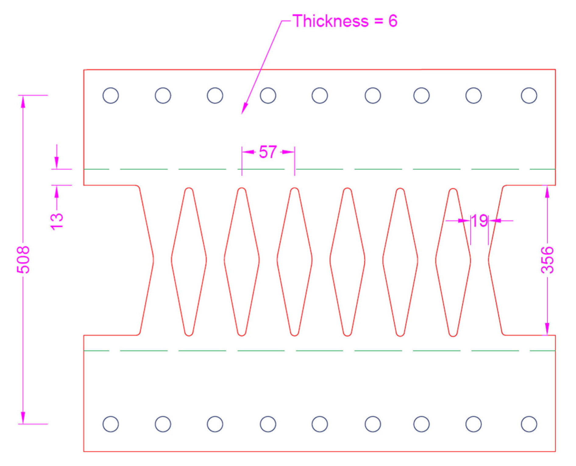
Validation of FEM methodology is performed by using the experimental data [44]. In Figure 5, the B09-56 specimen geometrical dimensions are illustrated. In addition, for the FEM analysis, the true stress and logarithmic strain material curves obtained from the coupon test are considered (Plate C [44]). The engineering yielding stress is 347 MPa, while the ultimate stress of the material is considered to be 435 MPa. At rupture displacement of 25 mm. Along with the same lines, a shell element with three nodes and the reduced integration mode (S3R) shell element was utilized in the FEM, with a maximum size of 3 mm. Also, the FEM comprised of a global geometrical imperfection (linked to the SSD model’s first local buckling Eigen shape and seven strips), and a one percent strip height amplitude strip (3.5 mm) [41].
A comparison between the results of the experimental test and the FEM model after loading indicated more than 91% agreement for predicting experimental results. [41]. It is shown that the FEM captures the mode of behavior, the ultimate buckled shape, and the buckling mode shape.

5. Optimization Process

The maximum stiffness and the full stress state could be used as the optimization objective function for the general topology optimization analysis [45]. Alternately, double optimization results of specified volume reduction ratio can be obtained, and compared with the optimization results for different volume reduction rates in order to obtain the final optimization scheme. Figure 6 illustrates the specific optimization process.
In this study, a set of 500 FE models is considered to optimize limit state functions. Various geometrical shapes are considered during the investigation of nonlinear load-deformation performance, and the pushover behavior of the structural shear links.
The following geometrical parameters are considered accordingly: links length (L) of 0.5 m for all the models; slenderness ratio varying between 10–50; damper taper ratio (a/R), which describes the inelastic behavior of links varying between 0.017 and 3; The R/L ratio which is between 0.2 and 0.95 indicating a major optimization parameter for the links’ performance. It is noted that damper optimization is typically conducted to improve the energy dissipation capability with less concentrated plastic strain areas yielding to more steady stress distribution in larger drift values [46].
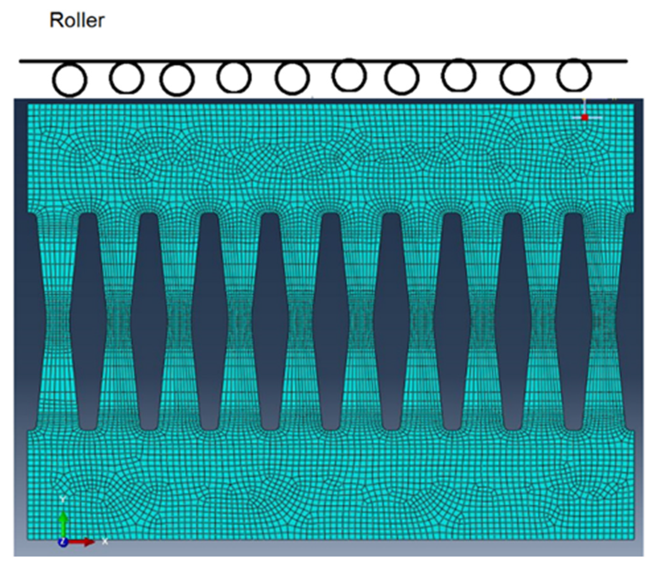
As is shown in Figure 7, the boundary condition of the steel shear panel damper at the bottom is fixed, and also restrained against the out-of-plane displacements at the top. An initial eigenvalue analysis is utilized for applying the initial imperfection displacement (L/250) based as a result of the first buckling mode. Following this process, the displacement-control load is applied on the link top edge, and cyclic results are monitored.
The yield stress for the material model is 300 MPa, and the ultimate stress is 345 MPa. A linear hardening between the ultimate point and yielding point was assumed. As previously indicated, the monotonic loading is applied at the top boundary as shown in Figure 7 for each model which is used for extraction of the pushover curve for determination of the dissipated energy and maximum plastic strains. The sensitivity of the mesh was done to achieve high precision in plastic strain and pushover results. The shear locking and hour glassing issues are monitored and prevented. Moreover, FEM accuracy was ensured by using a minimum of 8, 20, and 30 elements, at the middle section, top length, and inclined side lengths of steel shear steel dampers [3].
In this study, the synergy of system integration of both MATLAB and ABAQUS is explored for the optimization procedure. First, a python script is developed by ABAQUS and performed the analysis. The outcome of the analysis, using the optimization functions, is added to MATLAB for WOA application and variable updates resulting in a new model for the following iterations. With this process, it is observed that the more the number of iterations performed, the higher the accuracy of the optimal function. It is noted that both FE analysis and the WOA algorithm are combined based on the Python script implementation.

6. Discussion and Results

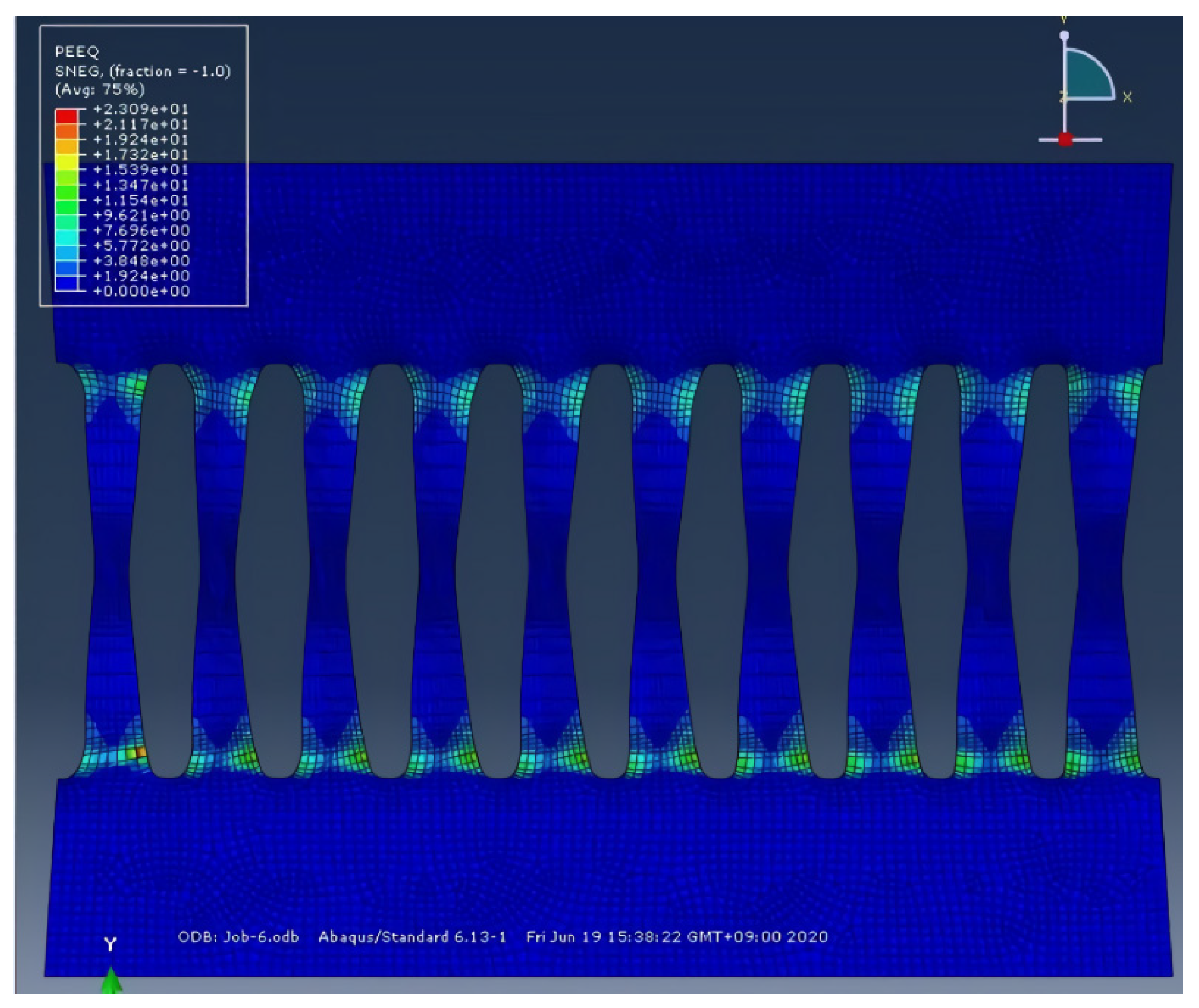
Figure 8 shows the plastic strain distribution representing the steel shear damper model at a 5% drift ratio. The FE steel shear panel damper model is compared with the optimized model based on the proposed method. The optimization functions are generated from WOA algorithms to achieve less fracture and maximize the energy dissipation capability. In addition, a previously defined loading condition was applied to the optimized models. As a result of the analysis, the distribution of the maximum plastic strain is generally uniformly distributed around 10% at the end of the damper. It is shown that WOA algorithm optimization could lead to a 51% reduction in the plastic strains at a 5% drift ratio compared to the initial models resulting in better resistance at higher drifts. Moreover, Figure 8 shows the optimal model plastic strain behavior which indicates low plastic strain values, especially around the geometrical changes. Overall, there was uniformity in the plastic strain distribution within the models in the optimal model compared to other models. This implies that the method of optimization permits more energy dissipation at a far position from the sharper angles and critical points with high strain concentration. Based on behavior investigations, this study shows four possible types of behavior. In the first group, plastic strains are concentrated at steel shear panel damper ends (the model with the highest PEEQ compared with other dampers at similar drift). The second group comprised models having plastic strains concentrated at the middle (position of shear yielding) [18,47]. In the third group, the buckling limit state occurs leading to the lesser ability for load-bearing resistance during medium to large drifts. Finally, the last group is the optimal model, where there is a simultaneous occurrence of shear and flexural yielding without attaining a brittle limit state. In this model, fracture occurrence is avoided and energy dissipation is optimum, thereby achieving the optimized limit state function.
Similarly, the stress distribution of selected models following a 5% drift ratio application is shown in Figure 9. As a result of the analysis, the maximum stress distribution was found to be uniformly distributed at about 350 Mpa at the end of the damper, similar to the distribution of maximum plastic strain. It is shown that the stress distribution of the optimal model is steadily demonstrated through the length of the link due to better materials implementation and higher energy dissipation. The study also showed that the geometrical properties of the optimal model are responsible for the mode of transition from flexure yielding to shear yielding, in accordance with the transitions equation provided by Farzampour and Eatherton [18,47]. In addition, the optimization analysis has shown that the models with thicker plates and better buckling resistance have a higher capability for dissipating. Therefore, the optimal steel shear panel damper models exhibit lesser fracture and improved energy dissipation capacity compared to other dampers.
Based on the normalized maximum PEEQ results (obtained from values associated with the optimal solution), behavioral comparisons are performed. Table 1 shows the results of the dissipated energy and optimization function. The buckling resistance models exhibit effective energy dissipation due to the occurrence of both shear and flexure yielding limit states simultaneously allowing uniform plastic strains and stresses distribution.
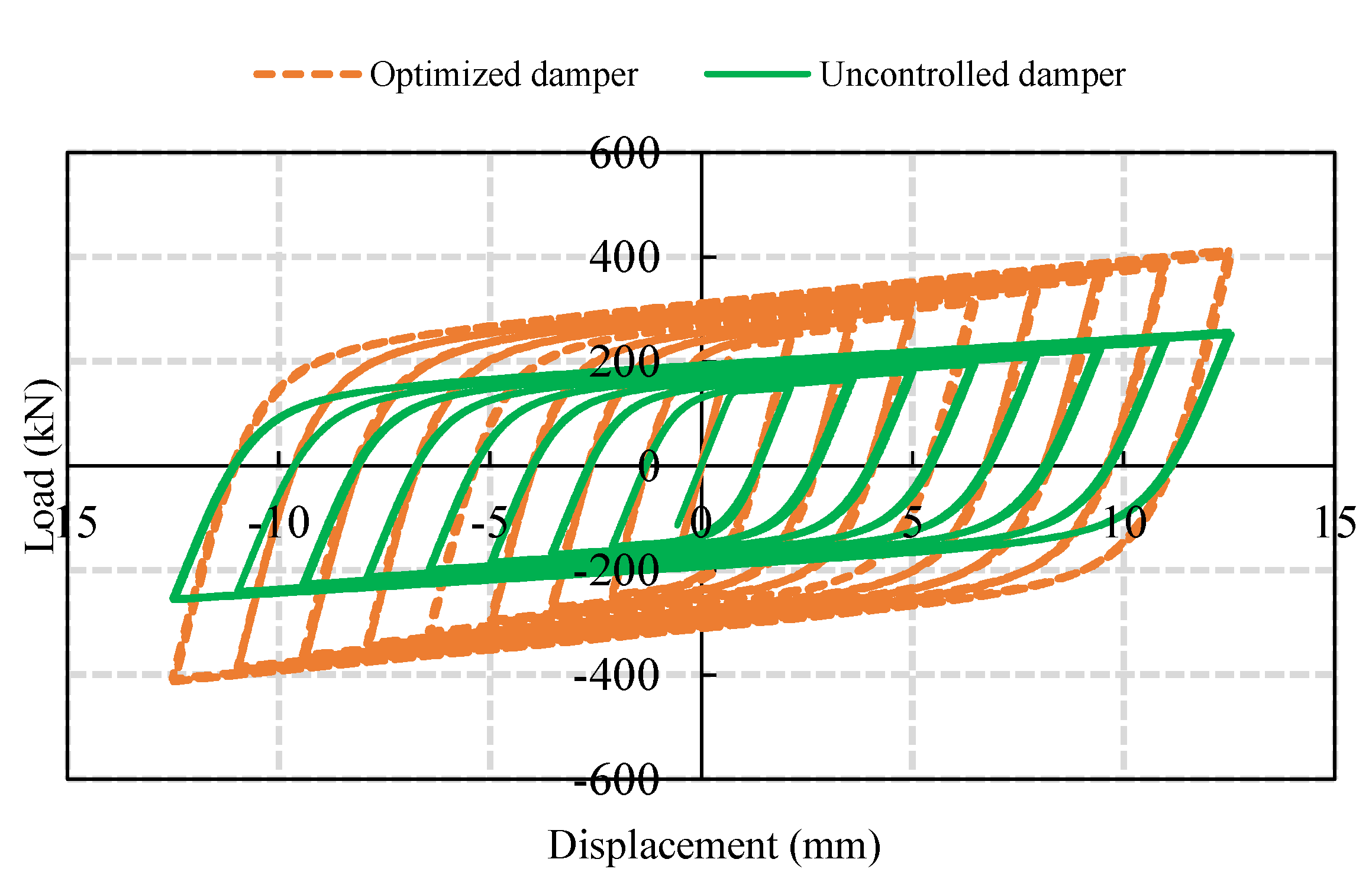
Following the determination of the damper optimal form, the initial and the optimized dampers are investigated for energy dissipation and hysteretic behavior. The overall hysteretic curves of the optimized and initial models are illustrated in Figure 10. From the simulation results and hysteresis curves, it is shown that interior damper optimization possesses a lower yield force and significantly higher stiffness.

7. Conclusions

In this study, the optimization of the curved metal dampers for improving the energy dissipation capacity was investigated. Three types of combined low yield steel plate dampers were considered for simplifying the deficiencies (high yield point, and low adjustability) of the traditional low yield point plate steel damper. The low yield point steel plates and common steel plates with proportions were proposed. The study utilized the concept of “maximum stiffness” and “full stress state,” for optimizing the dampers with interior hollows, boundary hollows, and ellipse hollows based on the alternating topology optimization technique. It is shown that the obtained three forms of combined low yield point steel plate dampers satisfied the optimization objectives.
An analysis of the FEM for various optimized combined steel plate dampers was computationally performed. The study has shown that the interior optimized damper is suitable for large deformation, and the energy dissipation capacity of the boundary optimized damper is relatively higher than conventional dampers. The study also used two types of optimization models having different material ratios for numerical simulation, and the results determine that it is possible to regulate the yield stress of the combined dampers by changing the material proportions.
In addition, over 300 butterfly-shaped links were generated following FEM validations. It should be noted that energy dissipation over concentrated PEEQ values is achieved based on the proposed optimization function. Using the WOA algorithms, it is possible to maximize energy dissipation capacity and minimize the plastic strain concentration over the links. The proposed optimization criteria show that optimal values of a geometry occur when it transforms flexural yielding to the shear yielding point. The proposed optimization procedure exhibits optimal dissipation of energy, with a minimum fracture. Finally, the optimal model demonstrates the development of the plastic strain concentration points at a far position from sharp angle geometrical sharpness resulting in desirable fracture resistance. It is noted that the proposed parametric study and optimization were developed for the specific shape of a commonly used damper; therefore, for extending and applying the work to other dampers types, further investigations are required.

Author Contributions

Conceptualization, project supervision, writing—review and editing Y.-C.K.; formal analysis, investigation, writing—original draft preparation S.J.M., A.F. and J.-W.H.; writing—review and editing Y.-C.K., S.J.M., A.F., J.-W.H., I.M. and P.O.A.; writing—review and editing J.-W.H. and I.M.; writing—review and editing, funding acquisition, J.-W.H. All authors have read and agreed to the published version of the manuscript.

Funding

This work was supported by the National Research Foundation of Korea (NRF) grant funded by the Korean government (MSIT) (NRF-2021R1A2B5B02002599).

Data Availability Statement

No new data were created or analyzed in this study. Data sharing is not applicable to this article.

Conflicts of Interest

The authors declare no conflict of interest.

References

  1. Vargas, R.E. Analytical and Experimental Investigation of the Structural Fuse Concept. Ph.D. Thesis, State University of New York, Buffalo, NY, USA, 2006. [Google Scholar]
  2. Mirzai, N.M.; Attarnejad, R.; Hu, J.W. Enhancing the seismic performance of EBFs with vertical shear link using a new self-centering damper. Int. J. 2018, 35, 57–76. [Google Scholar]
  3. Farzampour, A.; Khatibinia, M.; Mansouri, I. Shape optimization of butterfly-shaped shear links using Grey Wolf algorithm. Ing. Sismica 2019, 36, 27–41. [Google Scholar]
  4. Cetin, H.; Aydin, E. A New Tuned Mass Damper Design Method based on Transfer Functions. KSCE J. Civ. Eng. 2019, 23, 4463–4480. [Google Scholar] [CrossRef]
  5. Salari, S.; Hormozabad, S.J.; Ghorbani-Tanha, A.K.; Rahimian, M. Innovative Mobile TMD System for Semi-active Vibration Control of Inclined Sagged Cables. KSCE J. Civ. Eng. 2019, 23, 641–653. [Google Scholar] [CrossRef]
  6. Hu, X.; Lu, C.; Zhu, X.; Xie, X. A Theoretical Study of Estimating the Elastic Responses of Framed Self-Centering Wall Structures under Lateral Loading. KSCE J. Civ. Eng. 2020, 24, 3714–3725. [Google Scholar] [CrossRef]
  7. Sui, W.; Li, H.; Zhang, Q.; Wang, Z.; Jin, X. The Mechanical Properties of a New Corrugated Steel Plate Damper and Its Application in a Steel Arch Bridge. KSCE J. Civ. Eng. 2020, 24, 228–240. [Google Scholar] [CrossRef]
  8. Mirzai, N.M.; Cho, H.M.; Hu, J.W. Experimental study of new axial recentering dampers equipped with shape memory alloy plates. Struct. Control Health Monit. 2020, 28. [Google Scholar] [CrossRef]
  9. Mirzai, N.M.; Hu, J.W. Pilot study for investigating the inelastic response of a new axial smart damper combined with friction devices. Steel Compos. Struct. 2019, 32, 373–388. [Google Scholar] [CrossRef]
  10. Whittaker, A.; Bertero, V.; Alonso, J.; Thompson, C. Earthquake Simulator Testing of Steel Plate Added Damping and Stiffness Elements; Earthquake Engineering Research Center, University of California: Berkeley, CA, USA, 1989. [Google Scholar]
  11. Somarathna, H.; Raman, S.; Mohotti, D.; Mutalib, A.; Badri, K. The use of polyurethane for structural and infrastructural engineering applications: A state-of-the-art review. Constr. Build. Mater. 2018, 190, 995–1014. [Google Scholar] [CrossRef]
  12. Alehashem, S.M.S.; Keyhani, A.; Pourmohammad, H. Behavior and performance of structures equipped with ADAS & TADAS dampers. In Proceedings of the 14th World Conference on Earthquake Engineering, Beijing, China, 12–17 October 2008. [Google Scholar]
  13. Eldin, M.N.; Kim, J.; Kim, J. Optimum distribution of steel slit-friction hybrid dampers based on life cycle cost. Steel Compos. Struct. 2018, 27, 633–646. [Google Scholar] [CrossRef]
  14. Kim, J.; Kim, M.; Eldin, M.N. Optimal distribution of steel plate slit dampers for seismic retrofit of structures. Steel Compos. Struct. 2017, 25, 473–484. [Google Scholar] [CrossRef]
  15. Lor, H.A.; Izadinia, M.; Memarzadeh, P. Experimental evaluation of steel connections with horizontal slit dampers. Steel Compos. Struct. 2019, 32, 79–90. [Google Scholar] [CrossRef]
  16. Shahri, S.F.; Mousavi, S.R. Seismic behavior of beam-to-column connections with elliptic slit dampers. Steel Compos. Struct. 2018, 26, 289–301. [Google Scholar] [CrossRef]
  17. Ghamari, A.; Haeri, H.; Khaloo, A.; Zhu, Z. Improving the hysteretic behavior of Concentrically Braced Frame (CBF) by a proposed shear damper. Steel Compos. Struct. 2019, 30, 383–392. [Google Scholar] [CrossRef]
  18. Farzampour, A.; Mansouri, I.; Lee, C.-H.; Sim, H.-B.; Hu, J.W. Analysis and design recommendations for corrugated steel plate shear walls with a reduced beam section. Thin-Walled Struct. 2018, 132, 658–666. [Google Scholar] [CrossRef]
  19. Paslar, N.; Farzampour, A.; Hatami, F. Infill plate interconnection effects on the structural behavior of steel plate shear walls. Thin-Walled Struct. 2020, 149, 106621. [Google Scholar] [CrossRef]
  20. Farzampour, A.; Mansouri, I.; Hu, J.W. Seismic Behavior Investigation of the Corrugated Steel Shear Walls Considering Variations of Corrugation Geometrical Characteristics. Int. J. Steel Struct. 2018, 18, 1297–1305. [Google Scholar] [CrossRef]
  21. Farzampour, A.; Laman, J.A.; Mofid, M. Behavior prediction of corrugated steel plate shear walls with openings. J. Constr. Steel Res. 2015, 114, 258–268. [Google Scholar] [CrossRef]
  22. Lee, C.-H.; Ju, Y.K.; Min, J.-K.; Lho, S.-H.; Kim, S.-D. Non-uniform steel strip dampers subjected to cyclic loadings. Eng. Struct. 2015, 99, 192–204. [Google Scholar] [CrossRef]
  23. Lee, C.-H.; Lho, S.-H.; Kim, D.-H.; Oh, J.; Ju, Y.K. Hourglass-shaped strip damper subjected to monotonic and cyclic loadings. Eng. Struct. 2016, 119, 122–134. [Google Scholar] [CrossRef]
  24. Lee, C.-H.; Kim, J.; Kim, D.-H.; Ryu, J.; Ju, Y.K. Numerical and experimental analysis of combined behavior of shear-type friction damper and non-uniform strip damper for multi-level seismic protection. Eng. Struct. 2016, 114, 75–92. [Google Scholar] [CrossRef]
  25. Lee, C.-H.; Woo, S.-K.; Ju, Y.K.; Lee, D.-W.; Kim, S.-D. Modified Fatigue Model for Hourglass-Shaped Steel Strip Damper Subjected to Cyclic Loadings. J. Struct. Eng. 2015, 141, 04014206. [Google Scholar] [CrossRef]
  26. Hughes, T.J.R.; Cottrell, J.; Bazilevs, Y. Isogeometric analysis: CAD, finite elements, NURBS, exact geometry and mesh refinement. Comput. Methods Appl. Mech. Eng. 2005, 194, 4135–4195. [Google Scholar] [CrossRef] [Green Version]
  27. Shaaban, A.M.; Anitescu, C.; Atroshchenko, E.; Rabczuk, T. Shape optimization by conventional and extended isogeometric boundary element method with PSO for two-dimensional Helmholtz acoustic problems. Eng. Anal. Bound. Elem. 2020, 113, 156–169. [Google Scholar] [CrossRef]
  28. Auricchio, F.; DA Veiga, L.B.; Hughes, T.J.R.; Reali, A.; Sangalli, G. ISOGEOMETRIC COLLOCATION METHODS. Math. Models Methods Appl. Sci. 2010, 20, 2075–2107. [Google Scholar] [CrossRef] [Green Version]
  29. Bazilevs, Y.; Calo, V.; Cottrell, J.; Evans, J.; Hughes, T.; Lipton, S.; Scott, M.; Sederberg, T. Isogeometric analysis using T-splines. Comput. Methods Appl. Mech. Eng. 2010, 199, 229–263. [Google Scholar] [CrossRef] [Green Version]
  30. Chai, Y.; You, X.; Li, W.; Huang, Y.; Yue, Z.; Wang, M. Application of the edge-based gradient smoothing technique to acoustic radiation and acoustic scattering from rigid and elastic structures in two dimensions. Comput. Struct. 2018, 203, 43–58. [Google Scholar] [CrossRef]
  31. Deng, K.; Pan, P.; Sun, J.; Liu, J.; Xue, Y. Shape optimization design of steel shear panel dampers. J. Constr. Steel Res. 2014, 99, 187–193. [Google Scholar] [CrossRef]
  32. Pan, P.; Ohsaki, M.; Tagawa, H. Shape Optimization of H-Beam Flange for Maximum Plastic Energy Dissipation. J. Struct. Eng. 2007, 133, 1176–1179. [Google Scholar] [CrossRef] [Green Version]
  33. Farzampour, A.; Eatherton, M.R. Yielding and lateral torsional buckling limit states for butterfly-shaped shear links. Eng. Struct. 2019, 180, 442–451. [Google Scholar] [CrossRef]
  34. Farzampour, A.; Mansouri, I.; Dehghani, H. Incremental Dynamic Analysis for Estimating Seismic Performance of Multi-Story Buildings with Butterfly-Shaped Structural Dampers. Buildings 2019, 9, 78. [Google Scholar] [CrossRef] [Green Version]
  35. Farzampour, A. Structural behavior prediction of the Butterfly-shaped and straight shear fuses. Structures 2021, 33, 3964–3972. [Google Scholar] [CrossRef]
  36. Farzampour, A.; Eatherton, M.R. Parametric computational study on butterfly-shaped hysteretic dampers. Front. Struct. Civ. Eng. 2019, 13, 1214–1226. [Google Scholar] [CrossRef]
  37. Hajipour, F. Robust Radiotherapy Appointment Scheduling. Master’s Thesis, Concordia University, Montreal, QC, Canada, 2016. [Google Scholar]
  38. Mirjalili, S.; Lewis, A. The Whale Optimization Algorithm. Adv. Eng. Softw. 2016, 95, 51–67. [Google Scholar] [CrossRef]
  39. Rana, N.; Latiff, M.S.A.; Abdulhamid, S.M.; Chiroma, H. Whale optimization algorithm: A systematic review of contemporary applications, modifications and developments. Neural Comput. Appl. 2020, 32, 16245–16277. [Google Scholar] [CrossRef]
  40. Cao, Y.; Li, Y.; Zhang, G.; Jermsittiparsert, K.; Nasseri, M. An efficient terminal voltage control for PEMFC based on an improved version of whale optimization algorithm. Energy Rep. 2020, 6, 530–542. [Google Scholar] [CrossRef]
  41. Kiani, B.K.; Hashemi, B.H.; Torabian, S. Optimization of slit dampers to improve energy dissipation capacity and low-cycle-fatigue performance. Eng. Struct. 2020, 214, 110609. [Google Scholar] [CrossRef]
  42. Brando, G.; De Matteis, G. Design of low strength-high hardening metal multi-stiffened shear plates. Eng. Struct. 2014, 60, 2–10. [Google Scholar] [CrossRef]
  43. Lee, J.; Kim, J. Development of box-shaped steel slit dampers for seismic retrofit of building structures. Eng. Struct. 2017, 150, 934–946. [Google Scholar] [CrossRef]
  44. Ma, X.; Borchers, E.; Pena, A.; Krawinkler, H.; Billington, S.; Deierlein, G.G. Design and Behavior of Steel Shear Plates with Openings as Energy-Dissipating Fuses; Report No. 173; John A. Blume Earthquake Engineering Center: Stanford, CA, USA, 2010. [Google Scholar]
  45. He, H.; Wang, X.; Zhang, X. Energy-Dissipation Performance of Combined Low Yield Point Steel Plate Damper Based on Topology Optimization and Its Application in Structural Control. Adv. Mater. Sci. Eng. 2016, 2016, 5654619. [Google Scholar] [CrossRef] [Green Version]
  46. Farzampour, A. Evaluating Shear Links for Use in Seismic Structural Fuses. Ph.D. Thesis, Virginia Polytechnic Institute and State University, Blacksburg, VA, USA, 2018. [Google Scholar]
  47. Farzampour, A.; Eatherton, M.R. Parametric Study on Butterfly-shaped Shear Links with Various Geometries. In Proceedings of the 11th National Conference on Earthquake Engineering, 11NCEE, Los Angeles, CA, USA, 25–26 June 2018. [Google Scholar]
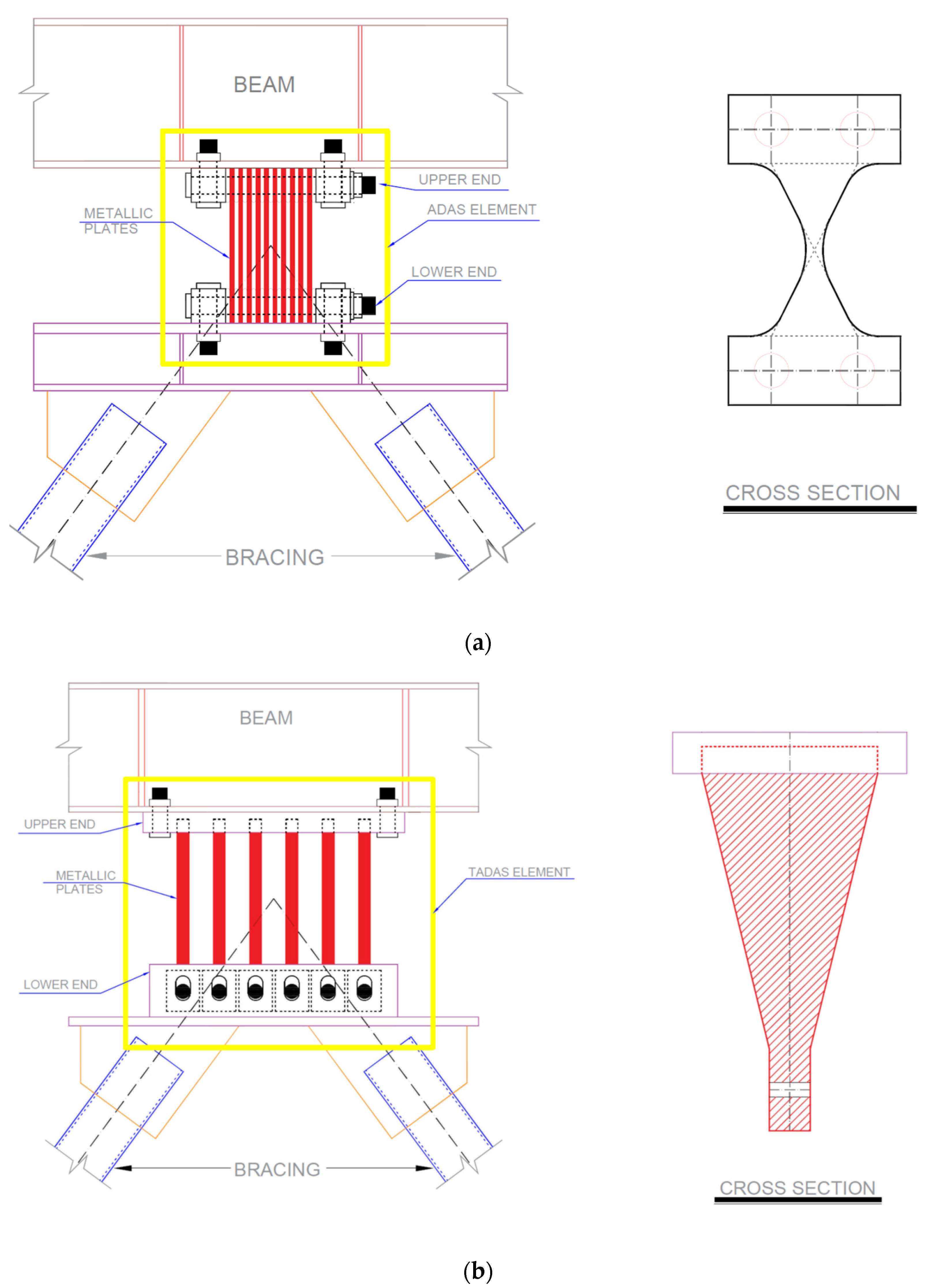
Figure 1. Configuration of (a) ADAS damper (b) TADS damper [12].
Buildings 12 00067 g001
Figure 2. Non-uniform steel dampers [22].
Buildings 12 00067 g002
Figure 3. The curved metal damper and considered parameters for optimization.
Buildings 12 00067 g003
Figure 4. Loading history adopted for the FEM analysis based on FEMA−461.
Buildings 12 00067 g004
Figure 5. B09−56 specimen geometrical dimensions (in mm) [41].
Buildings 12 00067 g005
Figure 6. Optimization process for shape optimization of steel dampers.
Buildings 12 00067 g006
Figure 7. Schematic geometrical properties of a typically curved metal damper.
Buildings 12 00067 g007
Figure 8. Plastic strain accumulation of steel shear panel damper.
Buildings 12 00067 g008
Figure 9. Von-Mises stress distribution for steel shear panel damper.
Buildings 12 00067 g009
Figure 10. Hysteretic behavior comparison of the optimized dampers and initial models.
Buildings 12 00067 g010
Table 1. Sample of the results for optimization study on the steel shear damper.
No.R (m)ta (m)Normalized PEEQ maxNormalized EdEd/[PEEQ Max]
10.010.010.0082.2770.00204454.48
20.010.010.1541.5520.0275512,942.72
30.010.010.31.3650.0329816,138.86
40.010.010.1541.80.0897632,200.82
50.010.010.32.5680.0960427,755.22
60.0050.010.0080.990.0326722,035.82
70.0050.010.1541.5040.1058441,170.14
80.0050.010.31.1990.1566117,418.1
90.0050.030.0082.4840.005051565.2
100.0050.030.1541.6960.0782634,796.81
110.00250.030.31.3260.0946455,264.65
120.00250.030.0082.0140.051318,161.97
130.00250.030.1541.5750.0558624,732.18
140.00250.030.32.1390.306984,241.59
150.00250.030.0081.010.10165,879.76
160.0010.030.1541.50.27027128,421.1
170.0010.030.30.90.618367,647.2
180.0010.050.0082.1620.0092461.76
190.0010.050.1541.6160.1468861,602.24
200.0010.050.31.2740.1712794,017.69
Publisher’s Note: MDPI stays neutral with regard to jurisdictional claims in published maps and institutional affiliations.