Article

Mitigation of Tsunami Debris Impact on Reinforced Concrete Buildings by Fender Structures

1
Department of Civil Engineering, Faculty of Engineering, Chulalongkorn University, Bangkok 10330, Thailand
2
Center of Excellence in Earthquake Engineering and Vibration, Department of Civil Engineering, Chulalongkorn University, Bangkok 10330, Thailand
*
Author to whom correspondence should be addressed.
Buildings 2022, 12(1), 66; https://doi.org/10.3390/buildings12010066
Submission received: 29 October 2021 / Revised: 21 December 2021 / Accepted: 7 January 2022 / Published: 10 January 2022

Abstract

:
Buildings located in coastal regions are prone to tsunami dangers, which often carry debris in the form of shipping containers and boats. This paper presents an approach for the design of fender structures to minimize debris impacts on buildings. The impact of shipping containers, which are categorized as large debris, is considered in the study. Since the weights of shipping containers are standardized, the impact energy can be related to other debris. For a fender structure, cone-type rubber fenders are used to resist the impact of the shipping container. Various fender reactions are considered as parameters to study the efficiency of the fenders. The displacement-controlled nonlinear static analysis is carried out to determine the building capacity. The energy approach for shipping container impact is used to evaluate the resistance of the building. Capacity curves, energy absorptions, inter-story drift ratios of the buildings with and without a fender structure, and the efficiency of the fender are presented. The buildings with a fender structure can absorb the energy from the impact of a loaded shipping container. Conversely, the building without a fender structure cannot resist the impact of a loaded shipping container. From the obtained results, a recommendation is given for buildings with a fender structure. The hydrodynamic force on the fender structure is transferred to the main building through the fender. Hence, the yield force of the fenders affects the performance of the main building that must be considered in the design.

1. Introduction

The 2004 Indian Ocean tsunami resulted in damage to structures in many countries around the Indian Ocean, including Thailand. The run-up heights of approximately 5 to 12 m were found on the western coast of southern Thailand, as the unprecedented tsunami caused over 5300 deaths and severe damage to buildings [1]. The effects of tsunami forces on buildings have been investigated in the past. Openings in buildings were found to reduce tsunami forces [2]. Lateral failure or deformation of the building and out-of-plane failure of walls were observed due to the lateral hydrodynamic and hydrostatic forces. Additionally, foundation failure due to scouring and overturning effect and uplift damage to precast slab were observed in many RC buildings [3]. Furthermore, the flooding water carries debris in the form of shipping containers, automobiles, parts of the structures, and even ships, during the occurrence of tsunamis. Debris types can be generally divided into three groups: small, moderate, and large debris, depending on the characteristic of mass, size, stiffness, and buoyancy [4]. Small size debris may not completely affect the structure. Field investigations have shown that structural failure mostly occurs from moderate and large debris strikes [4]. Therefore, buildings prone to high inundation levels in coastal areas must be sheltered from tsunami forces as well as debris impact.
The dominant forces considered for the design of tsunami-resistant buildings in tsunami-prone areas include hydrodynamic, hydrostatic, buoyant, surge, and debris impact forces. The drag coefficient is one of the important parameters for the evaluation of hydrodynamic force on the building, in which different drag coefficients are expressed depending on the objects [5,6,7,8]. Hydrostatic forces are critical for long structures, such as dikes and sea walls, while they are less relevant when water passes through buildings [8]. Surge forces were not found to exceed hydrodynamic forces in the circular element and cannot occur simultaneously with the hydrodynamic and debris impact forces [9,10,11]. The important parameter of tsunami forces is the flow velocity, which can vary with high uncertainty during a single tsunami event. Flow velocity depends on the flow depth. Several researchers have investigated the empirical coefficients of flow velocity with different experiments [1,9,12,13]. These investigations suggested that flow velocity’s empirical coefficients lie between 1.2 and 1.7.
A tsunami can cause massive wave and debris impacts, resulting in building destruction. Designing the entire building to resist these effects may be uneconomical. Therefore, the need of a mitigation method that minimizes the undesired loss or damage is essential. According to [1,2,14,15], the presence of openings in masonry infill or breakaway walls can significantly reduce the lateral tsunami forces on the building. The hydrodynamic force on the circular column was found to be lower than that on the rectangular column, resulting in a significant reduction of hydrodynamic force on the building [11]. The guideline of tsunami evacuation building indicates that the foundation, which may experience the scour and liquefaction effects, should be supported on piles with an appropriate degree of fixity at the column base [8]. Safeguarding structures through a suitable protection system was recommended for large debris cases [16,17]. A building with a protection system was studied in [17]. Two structures were connected with energy absorption devices, such as fenders, to absorb the impact of moving debris without inducing damage to the building. All tsunami loads occur on the building during a tsunami event, but only debris impact loads were considered in this literature. Fenders are energy absorption devices used as a shelter for marine structures to absorb the large berthing energies through their elastic and inelastic deformations [18].
Few studies have focused on tsunami pushover analysis for the hydrodynamic load pattern [19,20,21,22]. Constant height pushover (CHPO) and variable height pushover (VHPO) analyses were implemented to assess the response of the structure under the hydrodynamic force. CHPO and VHPO analyses are displacement- and force-controlled methods, respectively. In this literature, both pushover methods were considered on hydrodynamic load patterns using constant and variable inundation depths [21]. In previous studies, only the hydrodynamic load was used for the tsunami pushover analysis [19,20,21,22].
Thus far, the performance of the fender and the building system has not been thoroughly studied. Therefore, the efficiency of the fender and associated building should be investigated. In this study, a building coupled to a cone-type rubber fender is considered. The hydrodynamic force, buoyant force, and debris impact are considered. The impact of shipping containers, which are categorized as large debris, is considered in the study. Since the weight of a shipping container is standardized, the impact energy can be related to other debris. The debris impact is applied after the application of hydrodynamic force to simulate the actual situation. The capacity of the building under debris impact after applying the hydrodynamic force is obtained using the displacement-controlled nonlinear static analysis. This study pioneers the investigation of the performance of a building with fender structures, as illustrated in Figure 1. Finally, the formulations to select an appropriate fender and to consider the fender structure are proposed. The application is not limited to the cone-type rubber fender and the shipping container since the energy approach is used in developing the formulations.

2. Building Models and Loads

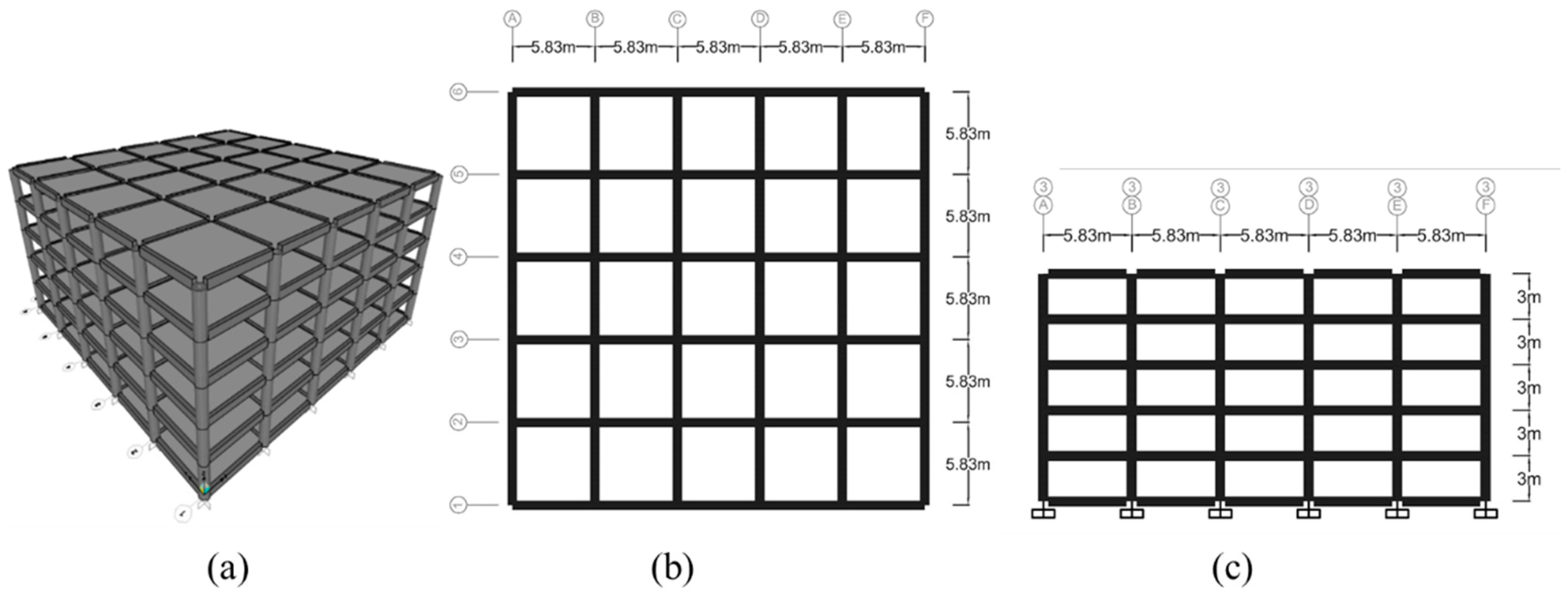
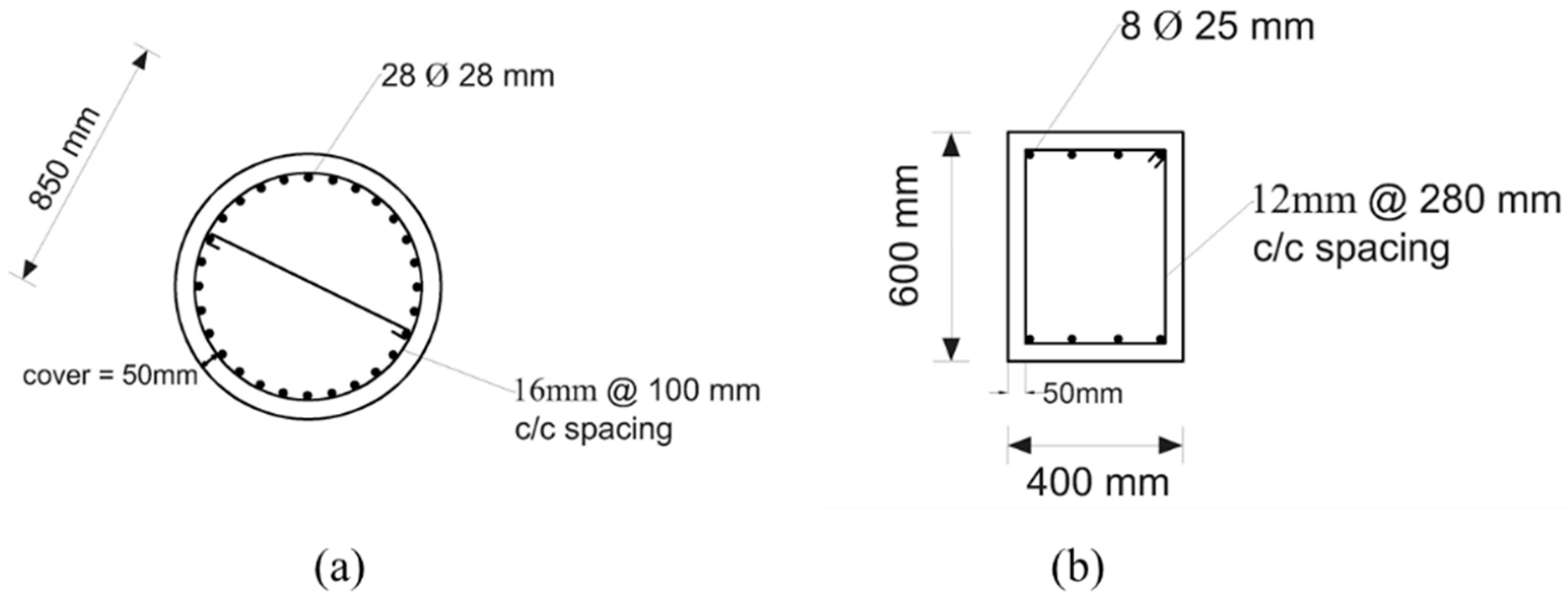
2.1. Details of Building

The target building was a five-story square-shaped RC building with a typical story height of 3 m, as shown in Figure 2. The plan size of the building and the number of stories depend on the area where a tsunami may occur and the required minimum area per evacuees [8]. The area of the structure was 850 m2 to accommodate 850 evacuees per floor. The height of the main building was 15 m. The design inundation depth considered in this study was 9 m. Circular columns, rectangular beams, and breakaway walls were considered to mitigate the tsunami effects. The pressure on the walls was not considered due to the breakaway walls. The hydrodynamic loads on the building were applied as uniformly distributed loads on columns and beams. The super-imposed dead load and live loads were taken as 1.5 kPa and 4.8 kPa, respectively.
The compressive strength of concrete was 53 MPa and the yield strength of longitudinal and transverse reinforcing steels was 500 MPa. Constant column and beam dimensions were utilized throughout the building. The building was designed in accordance with the tsunami load combinations to resist tsunami forces presented in FEMA P-646 [8]. The column and beam were designed according to ACI318 [23] to resist the tsunami. The cross-section dimension of 0.85 m in diameter was used. The flexural failure of the column was predicted according to ASCE 41-17 [24]. The beam cross-sectional dimension was 0.4 × 0.6 m. Longitudinal reinforcement ratios for beams and columns were 1.64 and 3%, respectively. For columns, the longitudinal bar size had a diameter of 28 mm, and the transverse bar size was 16 mm with 100 mm spacing. For beams, the longitudinal bar size was 25 mm in diameter, and the transverse bar size was 12 mm provided at a spacing of 280 mm. The slab thickness was kept at 200 mm. Table 1 and Figure 3 provide the structural properties of members.

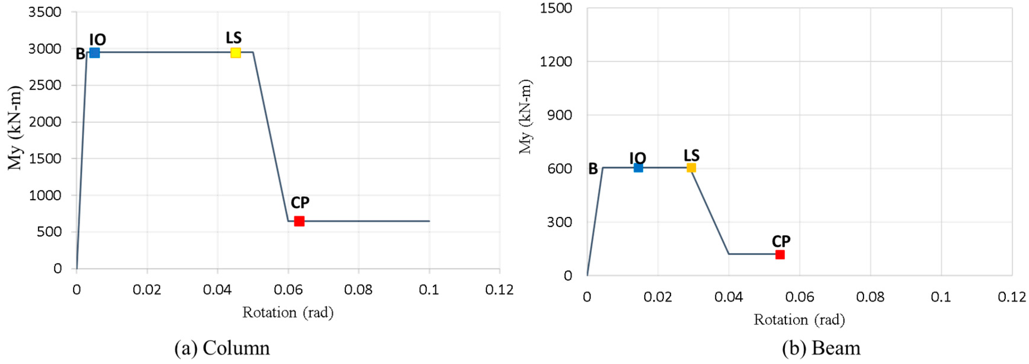
2.2. Nonlinear Properties of RC Members

To incorporate non-linear behavior of beams and columns, frame elements with lumped plasticity were used by defining plastic hinges at their both ends. User-defined hinges based on ASCE 41-17 recommendations were used in this study for the modeling of plastic hinges [24]. The confined concrete model by Mander et al. [25] and the simple steel stress-strain model with a strain hardening ratio of 0.01 were utilized for the section analysis in this study. The yield moment and corresponding curvature were obtained from the section analysis using strain compatibility of concrete and steel bars. The shear strength equation according to [26] was adopted to confirm that shear failure does not occur.
ASCE 41-17 presents the nonlinear lateral-force deformation relationship of typical plastic hinges for RC members. Figure 4 shows the moment-rotation relations of plastic hinges. The nonlinear modeling parameters and the acceptance criteria of the member, such as yielding (B), immediate occupancy (IO), life safety (LS), and collapse prevention (CP), are evaluated in accordance with [24]. Plastic hinges were considered at each member end [27]. Several plastic hinge length equations have been proposed in the literature [28,29,30,31,32,33]. Equation (1) by Berry et al. (2008) [33] was adopted in this study for the plastic hinges of beams and columns:
L p = 0.05 L + 0.1 f y d b / f c
where Lp is the plastic hinge length (m), L is the length from the critical section to the point of contra flexure, fc is the concrete compressive strength, and fy and db are the yield strength and the diameter of longitudinal reinforcement, respectively.

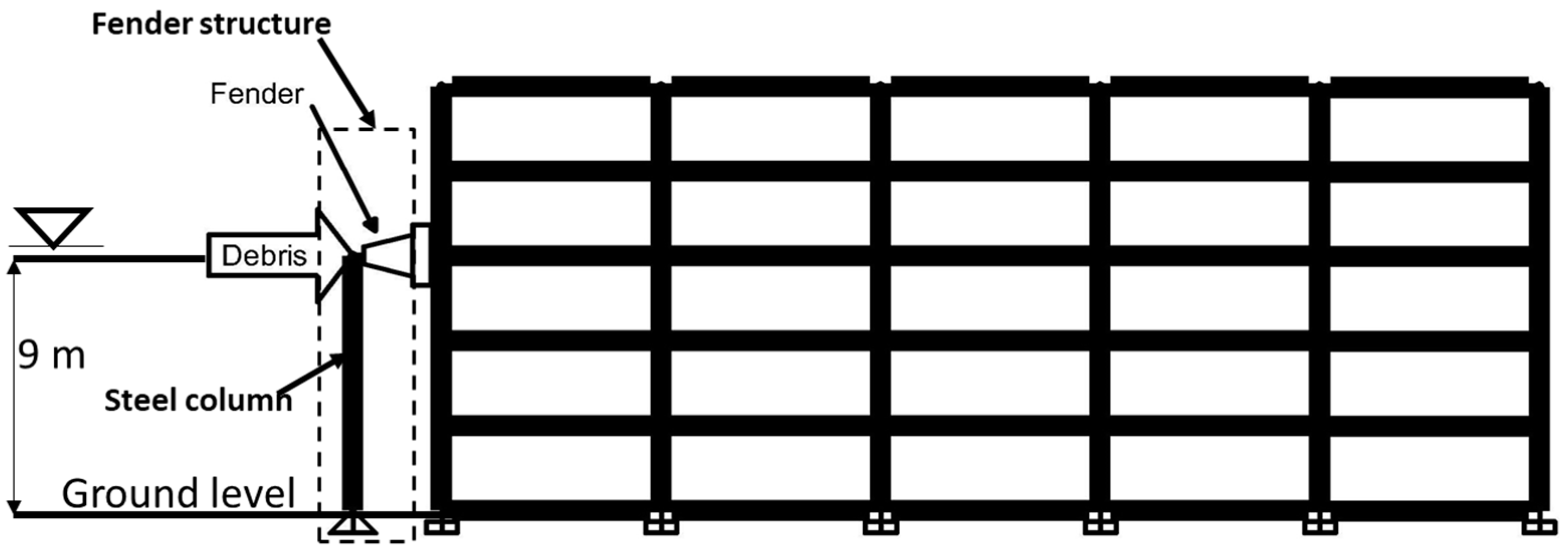
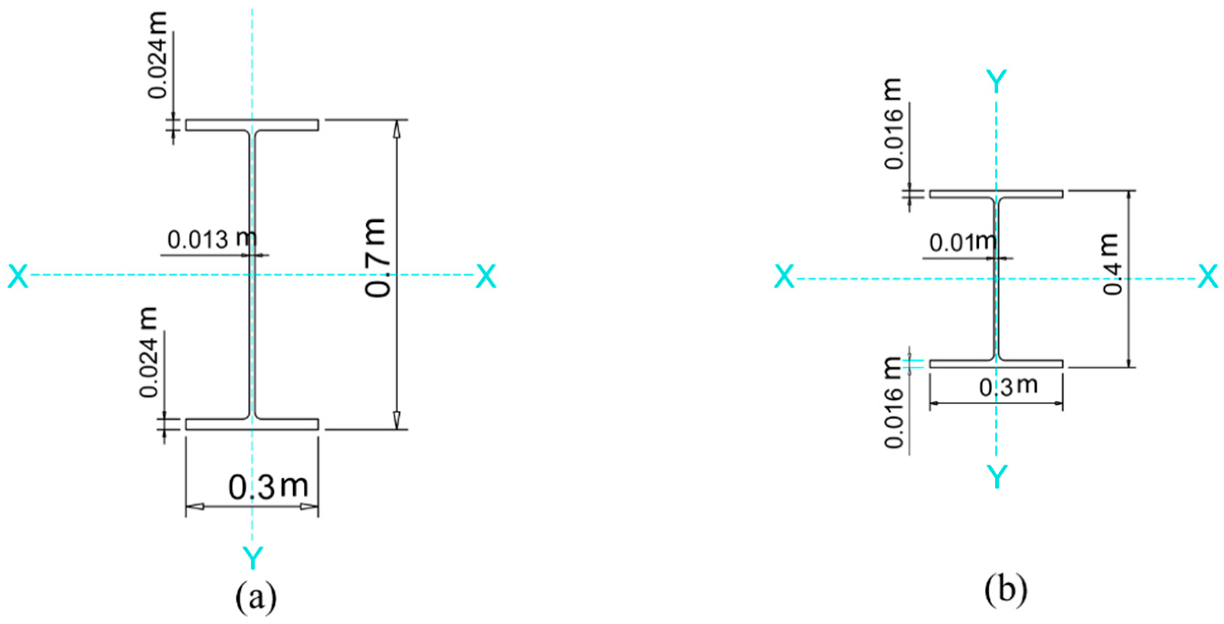
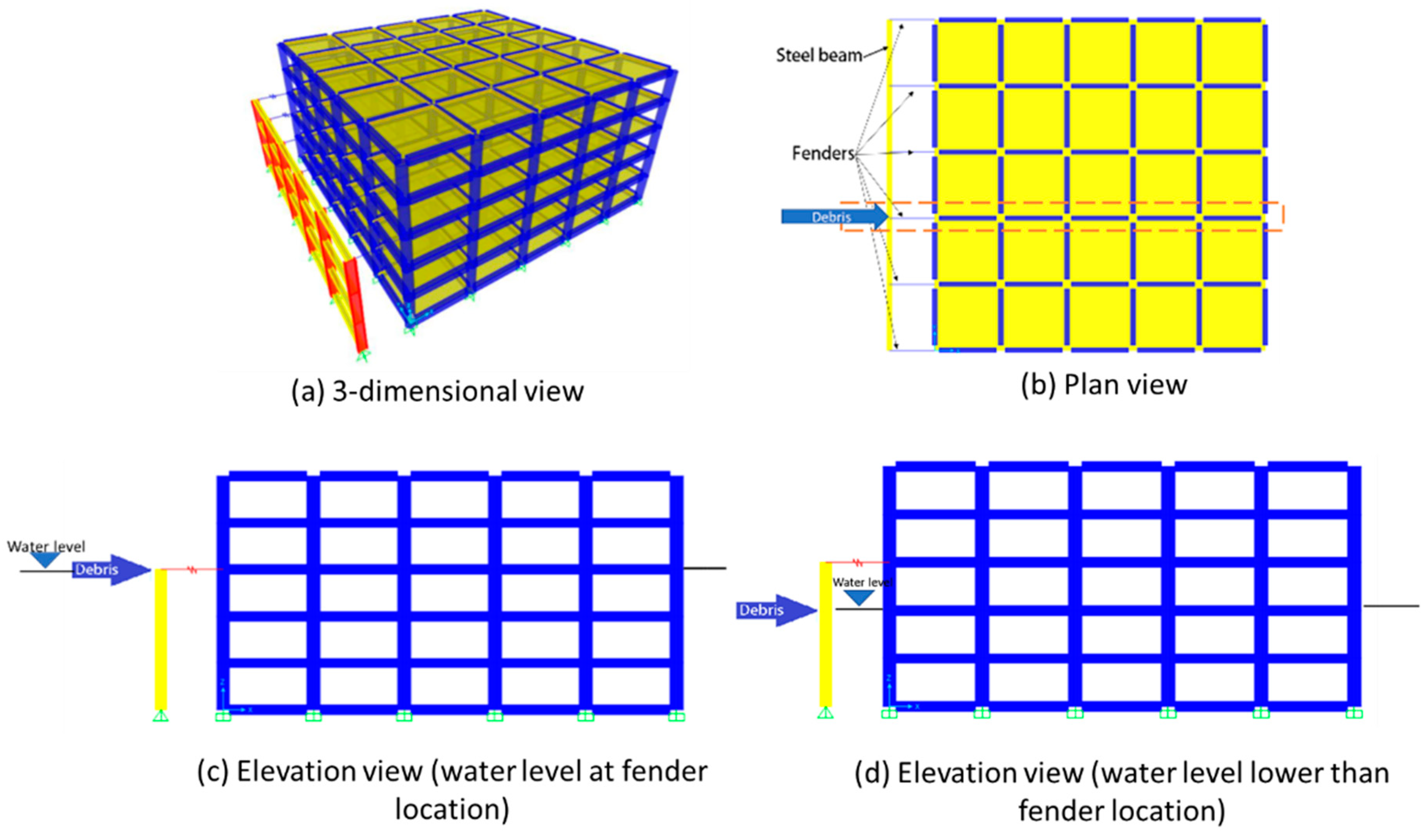
2.3. Model of Buildings with a Fender Structure

Energy absorption of a building to resist the tsunami forces and large debris impact can be increased by using the fender, which absorbs energy under large inelastic deformations. Figure 5 shows the arrangement of the fender structure in front of the building. The fender structure comprises (1) columns with supports free to rotate towards the building but restrained in the transverse direction to maximize deformation of fenders, (2) transfer beams which are pinned to the columns, and (3) cone-type rubber fenders. The debris impact may occur at a certain location in the plan. Since the top transfer beams are pinned to the columns, the impact energy is distributed to the nearest frames. It is conservative to consider that the impact occurs at the fender column, as shown in Figure 5b. Hence, a two-dimensional frame with the fender (Figure 5c) is studied in detail using SAP2000 [34]. The height of the fender structure is equal to the target water level. The impact energy due to the impact at the fender location is larger than the impact at the lower location (Figure 5d). The impact at the fender location (Figure 5c) is considered in the study. For the size of the steel structure, the steel column was 0.7 × 0.3 m, and the steel beam size was 0.4 × 0.3 m to resist the hydrodynamic force. Figure 6 shows the sections of the beam and column for the steel fender structure. The flanges of the steel members are placed towards the direction of tsunami flow so that the major axis of the section is subjected to the hydrodynamic force.
The variation of fender reactions was considered to investigate the efficiency of buildings with fender structures. Figure 7 shows the typical load-deformation relation of the cone fender as obtained from catalogs of some marine fenders. The actual behavior was idealized as an elastic-perfectly plastic model, while preserving the total dissipated energy and the yield force. Table 2 shows the parameters used for the fender structure.

2.4. Loads on Structure

Tsunami forces considered in the analysis are as follows.
(1)
Buoyant force
The buoyant force applied to the floors can be computed from [5,8] as:
F b = ρ g V
where ρ is the density of fluid taken as 1128 kg/m3 according to ASCE 7-16, g is the acceleration due to gravity, and V is the volume of water displaced by the submerged structure.
(2)
Hydrodynamic force
Using the parameters of the drag coefficient and flow velocity, the hydrodynamic force induced by quasi-steady flow can be computed from Equation (3). The hydrodynamic force acting on the structure was modeled with an equivalent uniform lateral load pattern, as suggested in the current design guidelines [5,6,8].
F d = ρ C d A u 2 2
where A is the projected area of the building normal to the flow direction, u is the flow velocity at the location of the building, and Cd is the drag coefficient [5].
(3)
Debris impact force
Impact from shipping containers can cause significant damage to the building. The impact energy of the moving container was determined in accordance with [35].
Kinetic   energy   of   moving   debris = 1 2 m u 2
where u is the flow velocity at the site and m is the mass of the debris. The general form of flow velocity can be expressed as follows:
u = α g h
where u is the flow velocity (m/s), α is the empirical velocity coefficient, and h is the inundation depth (m). According to the studies on tsunami flow velocity, the velocity coefficient values were proposed to vary between 1.2–1.7 [1,9,12,13]. A value of 1.25 was used for the velocity coefficient in the study because the value from [13] was close to the field observation in Thailand [1]. Table 3 summarizes the parameters used to evaluate the tsunami forces on the building.
(4)
Load combinations
For the strength design of the building, the tsunami forces were combined with the gravity load effect according to [8].
Load   combination   1 = 1.2 ( D L + S D L ) + 1 L L R E F + 0.25 L L + 1 ( D r a g + B u o y a n c y )
Load   combination   2 =   0.9 ( D L + S D L ) + 1 ( D r a g + B u o y a n c y )
where DL is the dead load, SDL is the super-imposed dead load, LLREF is the live load on a tsunami refuge floor level, and LL is the live load outside of the refuge area.

3. Analysis

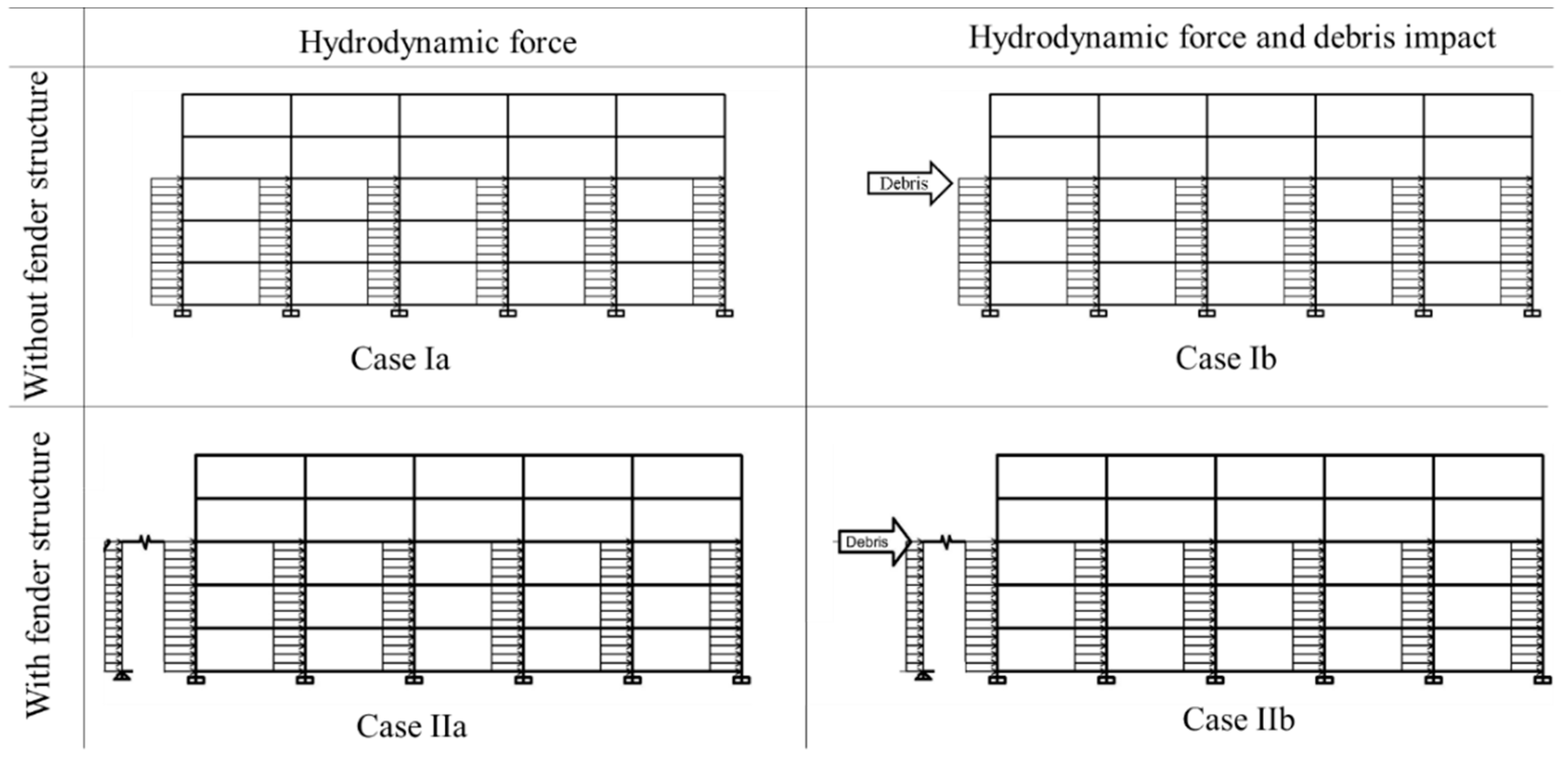
3.1. Analytical Cases

In this study, hydrodynamic force was applied first and then debris impacts were applied using the displacement-controlled nonlinear static analysis. This study examined two cases in the building analysis, namely, case I, i.e., the building without a fender structure, and case II, which referred to the building with a fender structure as shown in Figure 8. The capacity of the building under different cases was obtained using the nonlinear static analysis. The resistance of the building was evaluated using the energy method, in which the kinetic energy of the debris is absorbed by the strain energy of the building.

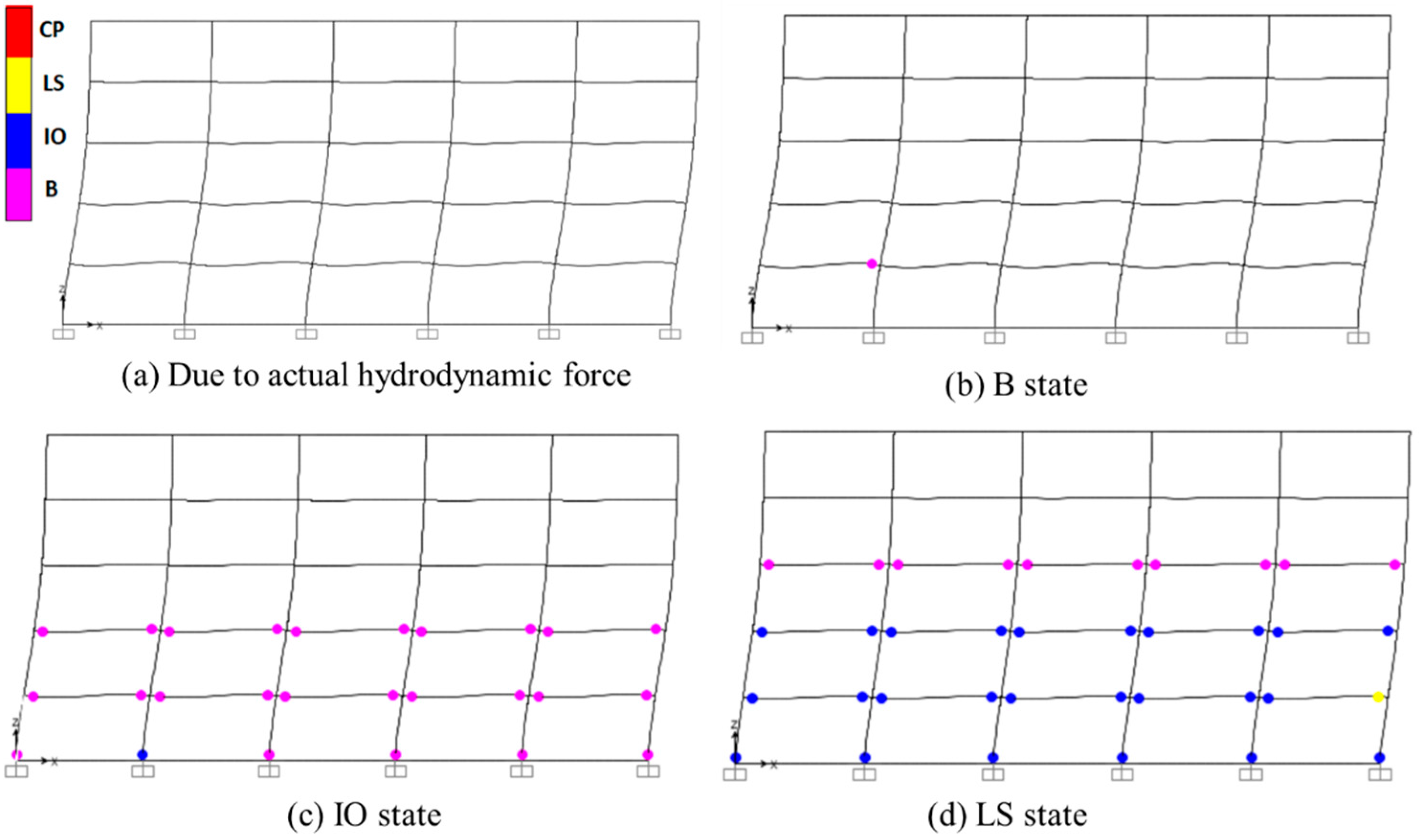
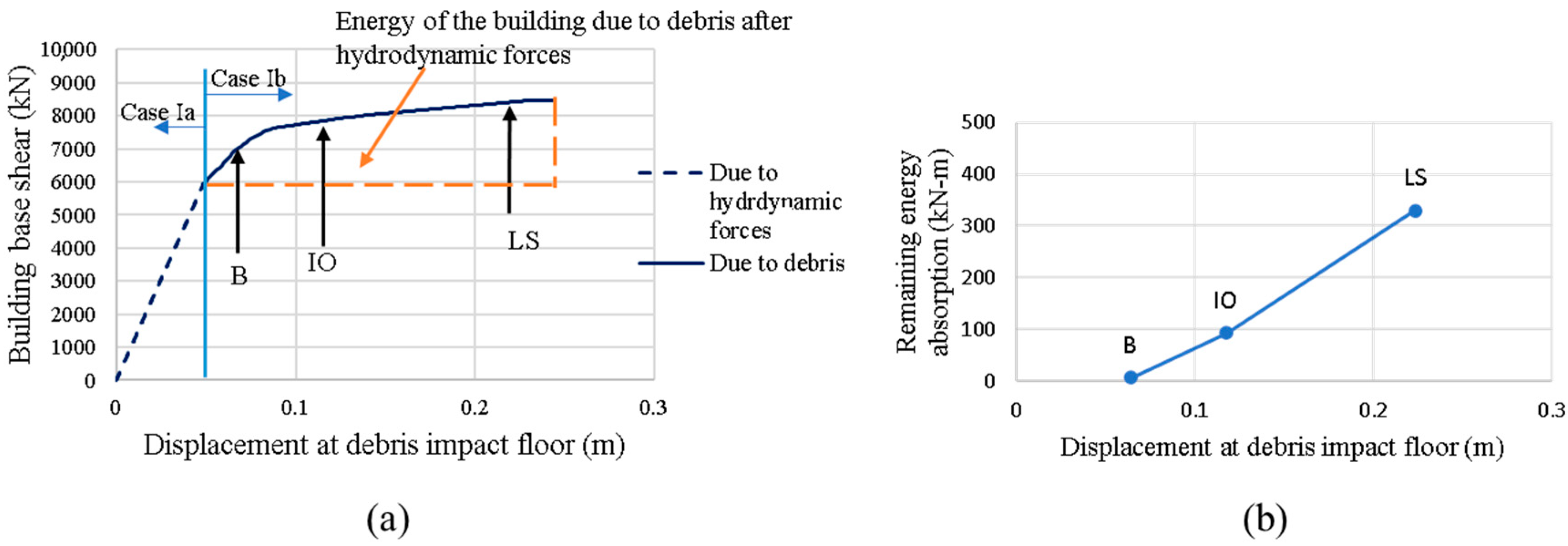
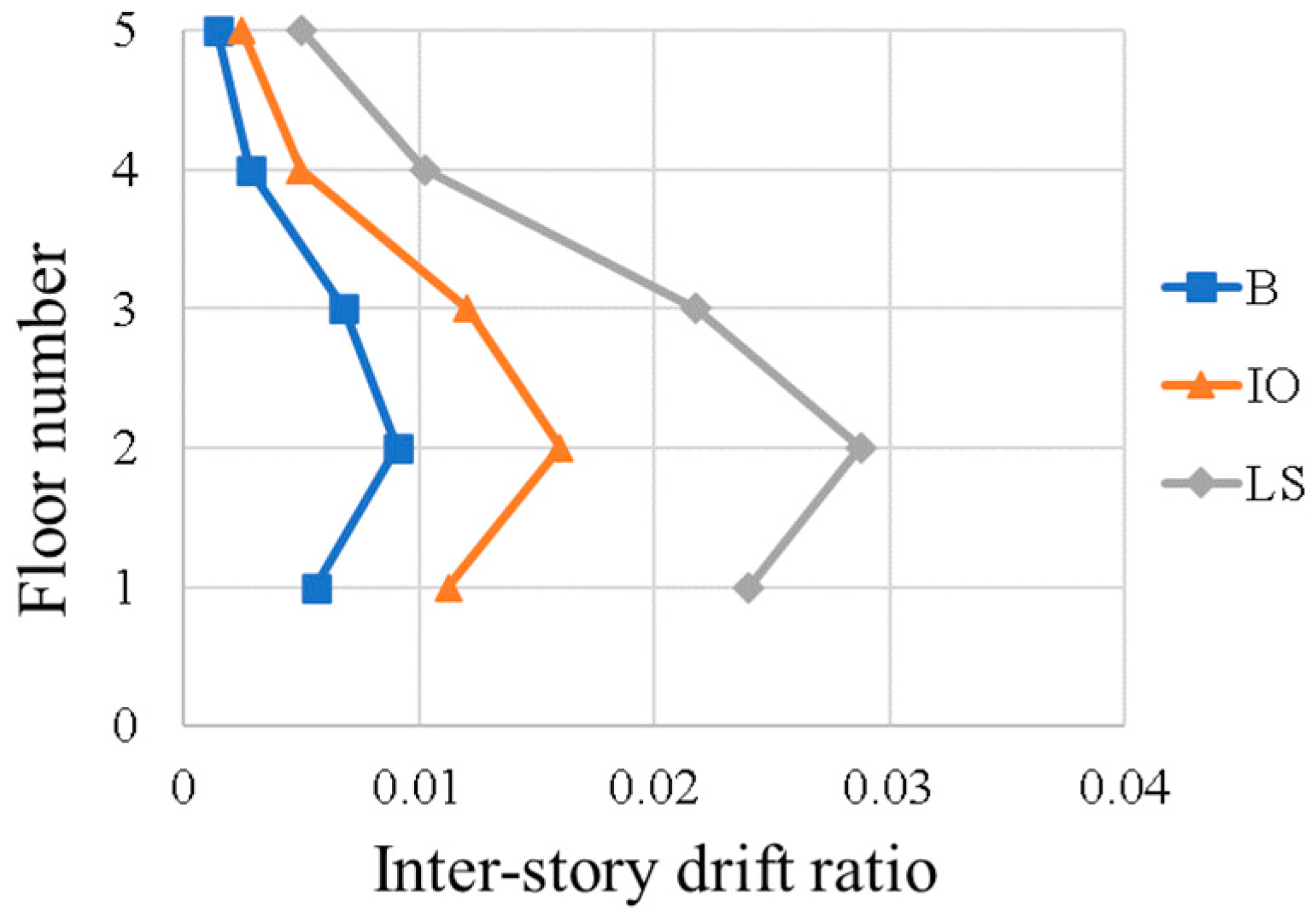
3.2. Response of the Building without a Fender Structure (Cases Ia and Ib)

Figure 9 shows the deformation of the building due to the hydrodynamic force and debris impact. No failure mechanisms were observed in the building against the hydrodynamic force (case Ia). The flexural moments of members under the hydrodynamic force did not reach the yield point because the building was designed using the load combination accounting for the hydrodynamic force. Referring to case Ib, beams developed the LS state earlier than columns. Consequently, this failure mechanism corresponds to the strong column–weak beam theory. After reaching the LS state, the building exhibited extensive damage in beams.
The force–deformation relation of the building under the hydrodynamic force is shown as a dashed line in Figure 10. The base shear was 5946 kN. No plastic hinge formation was observed. The remaining energy for the impact of debris was evaluated from Figure 10a and presented in Figure 10b. The remaining base shear capacities above the hydrodynamic force at B, IO, and LS states were 887, 1917, and 2488 kN, respectively. Figure 11 shows the inter-story drift ratio of the building due to debris impact at each performance state. As can be seen in Figure 11, the largest inter-story drift ratio was found at the second floor when the building reached its LS state.
The energy absorbed by the building was compared with the kinetic energy of different kinds of impact by shipping containers, as shown in Figure 12. It can be seen that the building could only resist the impact of the empty shipping container (shown by the threshold of vertical orange line).

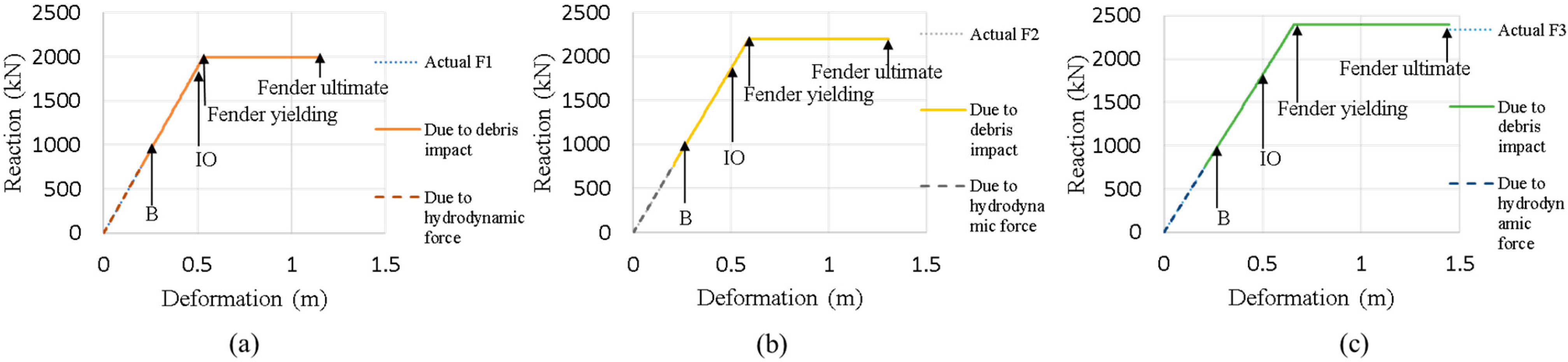
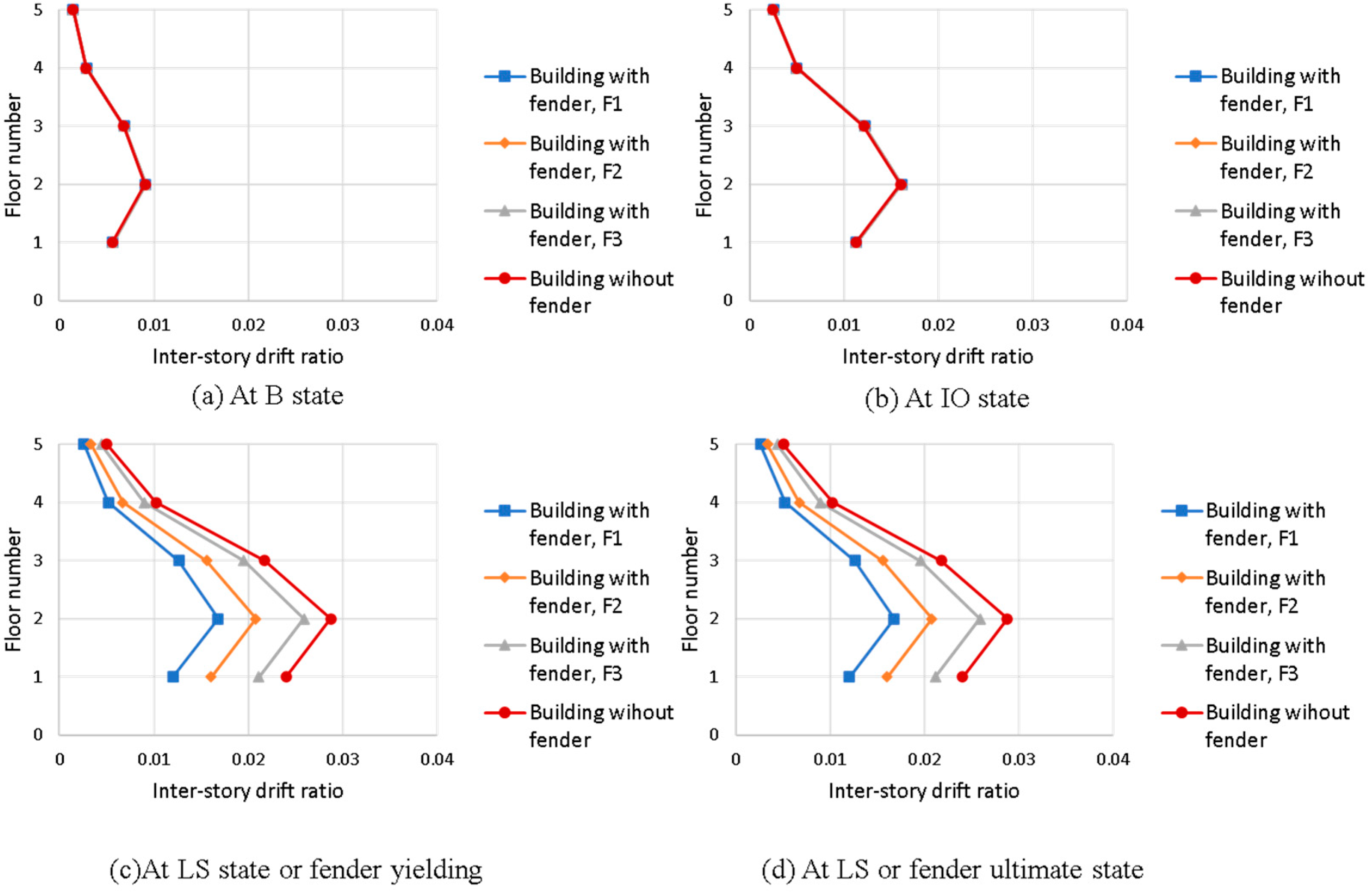
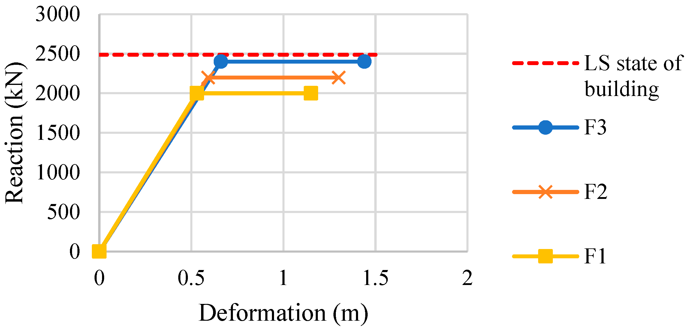
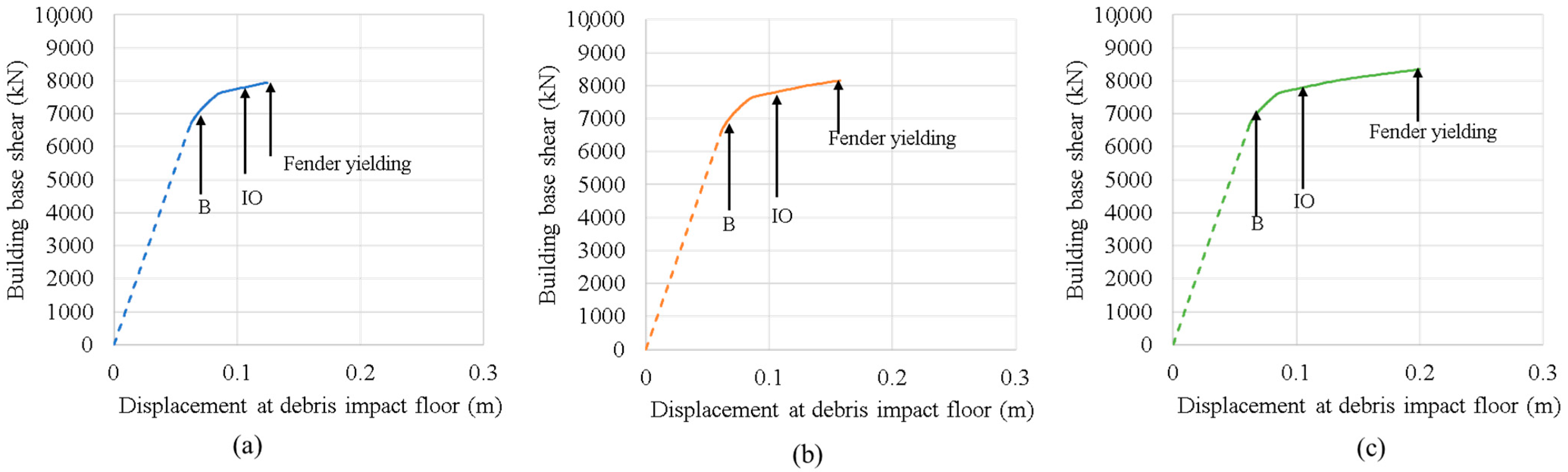
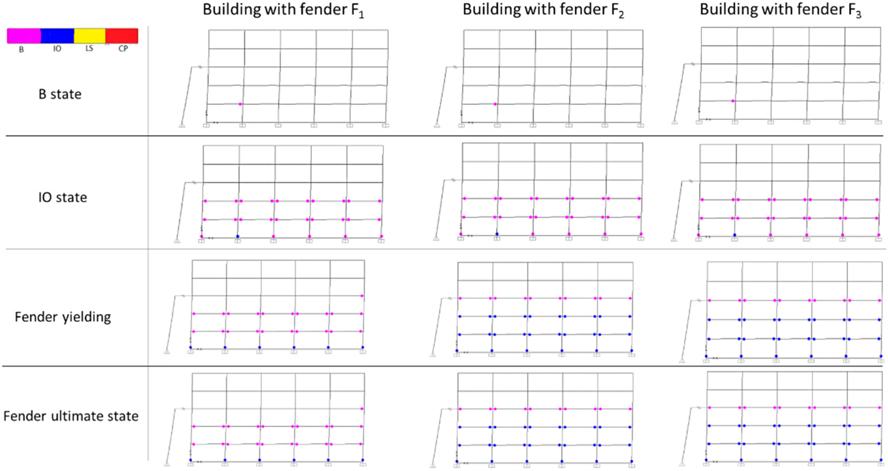
3.3. Response of the Building with the Fender Structure (Cases IIa and IIb)

It is important to note that the fender force transferring to the structures is limited by the yield force of the fender. Hence, the fender yield force was set lower than the force at the LS state of the building to ensure the safety of the building. Table 4 shows the parameters used in the fender structure. Fenders were selected from a commercial catalog of cone-type marine fenders based on the fender forces while maintaining the same stiffness to systematically compare the response. Hence, different fender lengths were obtained against different forces. The distance between the building and the fender structure was 2.5 m, which was chosen according to the fender lengths. The fender yield force was set lower than the remaining base shear capacity at the LS state, which was equal to 2488 kN. Figure 13 shows the force–deformation relation of the fenders used in the analysis.
The hydrodynamic force was initially applied to the building and fender structure, as shown in Figure 8. Fender reactions against hydrodynamic force was approximately one-third of their capacities, as shown in Figure 14. Figure 15 shows the relationship between the base shear and displacement of the building. Since the fender stiffness is constant, global force–deformation curves for all fender cases were identical in the initial stage, as shown in Figure 15. The total hydrodynamic force on the building with a fender structure was approximately 6706 kN, which was larger than the hydrodynamic force from the building without a fender structure (5946 kN). This is because the hydrodynamic force acts on the fender structure and the force is transferred to the building through the fender. Hence, the total base shear due to the hydrodynamic force is increased for the building with the fender structure. After applying the hydrodynamic force, the capacity of the building under debris impact was obtained using the displacement-controlled nonlinear static analysis. The maximum base shear of the building due to debris impact was limited by the fender yield force, as shown in Figure 15. It is seen that the higher the fender yield force, the larger the energy absorption. Note that the fender yield force was kept lower than the force at the LS state.
Figure 16 shows the plastic hinge formation of the building with a fender structure. No plastic hinge formation occurred under the hydrodynamic force. Figure 9 shows that the building without a fender structure suffered damage in the structure due to the debris impact. However, Figure 16 reveals no failure in the building owing to the efficiency of the fender structure. As in the case of a building with a fender structure, plastic hinge formation in the building was found only before yielding of the fender. The fender experienced a large inelastic deformation from yielding to its ultimate point. According to this observation, the fender with a capacity lower than that of the building at the LS state can effectively absorb the energy by its inelastic deformation without inducing critical damage to the main building.
Figure 17 shows the inter-story drift ratio of buildings with and without a fender structure. It is evident that the inter-story drift ratios of the building with and without the fender structure are identical for the B and IO states. As shown in Figure 17c,d, as yield forces of fenders F1, F2, and F3 were lower than the base shear of the building at its LS state, the inter-story drift ratios were lower than that of the building without the fender structure at the same state. Once the fender reached the yielding point, the force transferred to the building was limited. Hence, there was no further increase of the inter-story drift. This result clearly illustrates the benefit of the fender structure.
Figure 18 illustrates the energy absorbed by the building with and without the fender structures due to debris impact. Various states of the structural performance are presented. The major portion of energy absorption apparently arises in the fender structure. The fender yielding limited the force to the building, resulting in limited energy absorption and damage in the building. Figure 19 shows the total energy absorbed by the building with fenders, compared with the impact energy by the shipping container. Apparently, the energy absorption of the structure was increased significantly and was adequate to resist the impact by a loaded shipping container, while the fender F3 resulted in the highest energy absorption.

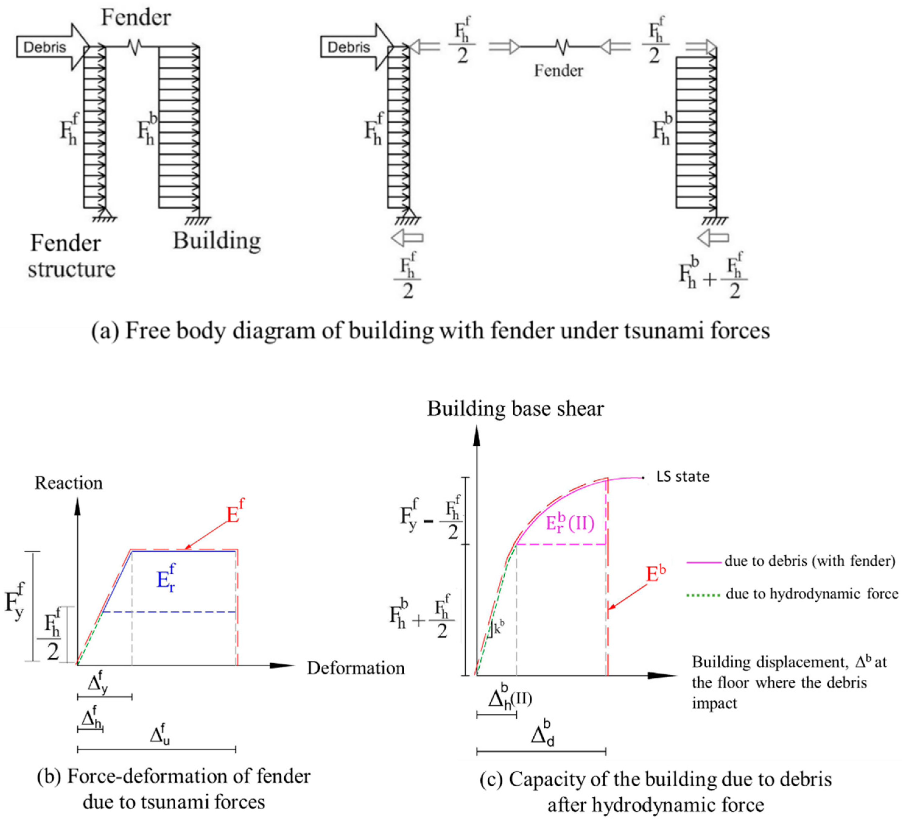
4. Design Recommendations for Buildings with a Fender Structure
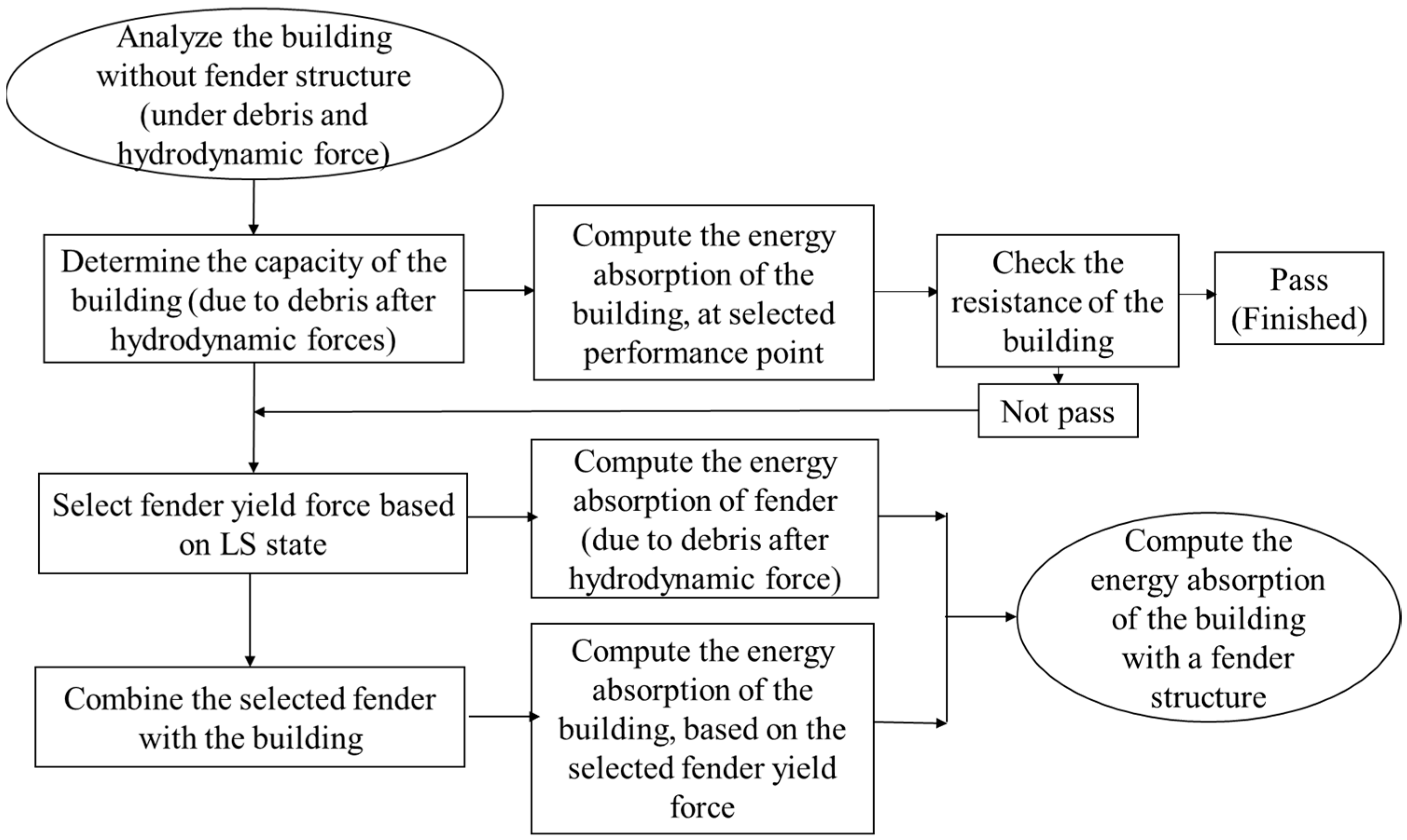
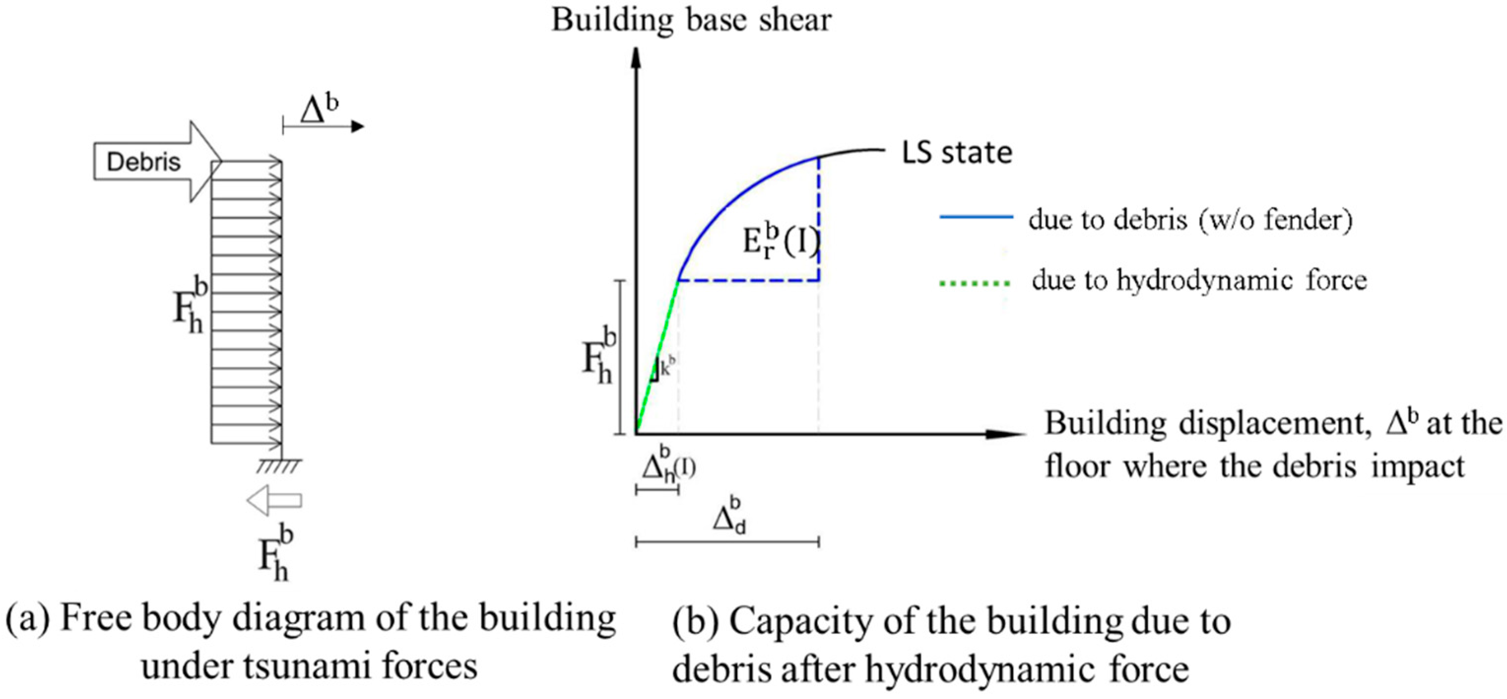
4.1. Concept

The concept for the selection of the fender structure is proposed to account for the combined behavior of the fender and the building. The selected fender yield force for the building with a fender structure should be taken from the base shear force at the performance state of the main building without inducing failure, preferably the LS state. Figure 20 summarizes the recommendation of the proposed design system.
Figure 21 illustrates the simplified model for the building without a fender structure to which the hydrodynamic force is initially applied. Then, the debris impact is applied to the building. The energy absorbed by the building is obtained on the basis of the capacity curve using the nonlinear static analysis. Figure 22 shows the simplified model for the building with a fender structure in which the hydrodynamic force is applied not only on the building but also on the fender structure. Then, the debris impact is applied to the fender structure. The energy absorbed by the building with a fender structure can be computed on the basis of the selected fender yield force without the need to perform a nonlinear static analysis.
The variables in Figure 21 and Figure 22 are defined as:
  • Δ h b ( I ) = displacement of the building without a fender structure due to hydrodynamic force;
  • Δ h b ( I I ) = displacement of the building with a fender structure due to hydrodynamic force;
  • Δ d b = displacement of the building due to debris after applying hydrodynamic force;
  • Δ h   f = displacement of the fender due to hydrodynamic force;
  • Δ y   f = displacement of the fender at the fender yielding state;
  • Δ u f = displacement of the fender at the fender ultimate state;
  • F h f = hydrodynamic force on the fender structure;
  • F h b = hydrodynamic force on the building;
  • F y f = fender yielding force;
  • Eb = energy absorption of the building;
  • Ef = energy absorption of the fender;
  • E r f = energy absorption of the fender due to debris after applying hydrodynamic force;
  • E r b ( I ) = energy absorption of the building without a fender structure due to debris after applying hydrodynamic force;
  • E r b ( I I ) = energy absorption of the building with a fender structure due to debris after applying hydrodynamic force;
  • E r T o t a l = total remaining energy absorption of the building with a fender structure due to debris after applying hydrodynamic force;
  • kb = initial stiffness of the building.
In Figure 22b, the remaining energy of the fender due to debris after applying hydrodynamic force is as follows:
E r f = 0.5 × ( F y f F h f ) [ ( Δ u f Δ y f ) + ( Δ u f Δ h f ) ]
In Figure 22c, the building with a fender structure under hydrodynamic force is displaced more than the building without a fender structure. This is attributed to the hydrodynamic force transferred from the fender structure. Therefore, the displacement of the building with a fender structure caused by the hydrodynamic force is as follows:
Δ h b ( I I ) = ( F h b + 0.5 F h f ) k b
Notably, the remaining energy absorbed by the building with a fender structure is lower than that of the building without a fender structure. According to Figure 22c, the remaining energy absorption of the building with a fender structure due to debris after applying the hydrodynamic force is as follows:
E r b ( I I ) = E r b ( I ) 0.25 F h f ( 2 Δ d b Δ h b ( I ) Δ h b ( I I ) )
The total remaining energy absorption of the building with a fender structure shall be larger than the kinetic energy of the debris impact as follows:
E r T o t a l = E r f + E r b ( I I ) E D
where ED is the kinetic energy of debris impact.

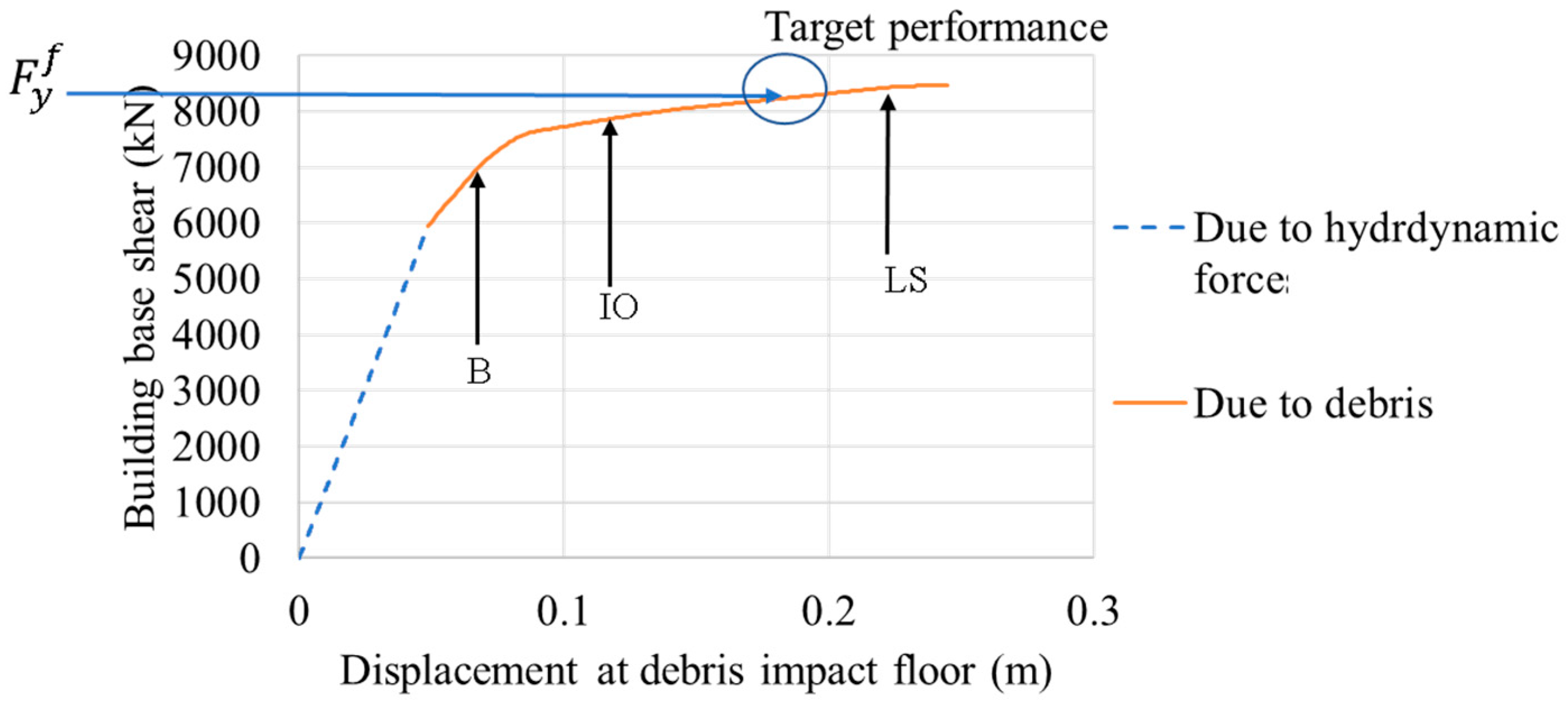
4.2. Sample Application of the Proposed Method

The sample application for the proposed method is considered for the building with a fender structure to resist the impact of a 40 ft loaded shipping container. The building used in this application was the same as the target building used in Section 3.1. The application of hydrodynamic force and debris impact was also the same. Therefore, the capacity curve of the building without a fender structure and the energy absorbed by the building were obtained from Section 3.2.
The capacity of the main building at the LS state was used to design the fender. The fender yield force was set to be lower than the force at the LS state of the building to ensure the safety of the building.
Trial fender size is F y f = 2300 kN, Lf = 1.6 m, Δ y f = 0.53 m, and Δ u f = 1.15 m.
From the capacity curve shown in Figure 23, the following information related to the selected fender was obtained: Δ d b = 0.185 m, Δ h b ( I ) = 0.049 m, kb = 121,347 kN/m, F h f = 1519 kN, F h b = 5946 kN, and E r b ( I ) = 237 kN − m.
Using Equation (8), the remaining energy of the fender due to debris after hydrodynamic force was calculated as:
E r f = 0.5 × ( F y f F h f ) [ ( Δ u f Δ y f ) + ( Δ u f Δ h f ) ] = 1229   kN
Using Equation (9), the displacement of the building with a fender structure due to hydrodynamic force was found to be the following:
Δ h b ( I I ) = ( F h b + 0.5 F h f ) k b = 0.055   m
Using Equation (10), the remaining energy absorption of the building with a fender structure due to debris after applying hydrodynamic force was as follows:
E r b ( I I ) = E r b ( I ) 0.25 F h f ( 2 Δ d b Δ h b ( I ) Δ h b ( I I ) ) = 136   kN m
According to Equation (11), the total remaining energy was as follows:
E r T o t a l = E r f +   E r b ( I I ) = 1229 + 136 = 1365 kN − m > Kinetic energy of 40 ft shipping container (1190 kN − m).
Therefore, the selected fender size was suitable for the building with a fender structure to resist the impact of a 40 ft container impact.

5. Conclusions

This study established a performance-based approach for the building with a fender structure. It introduced a reinforced-concrete building with a fender structure under tsunami forces and debris impact using displacement-controlled nonlinear static analysis. The building with a fender structure utilized the cone-type rubber fenders for the connection between the structures. The behavior of fenders was observed with the performance of the building. The kinetic energy of the shipping containers was evaluated to compare the resistance of buildings with and without fender structures. From the study, the following conclusions can be deduced:
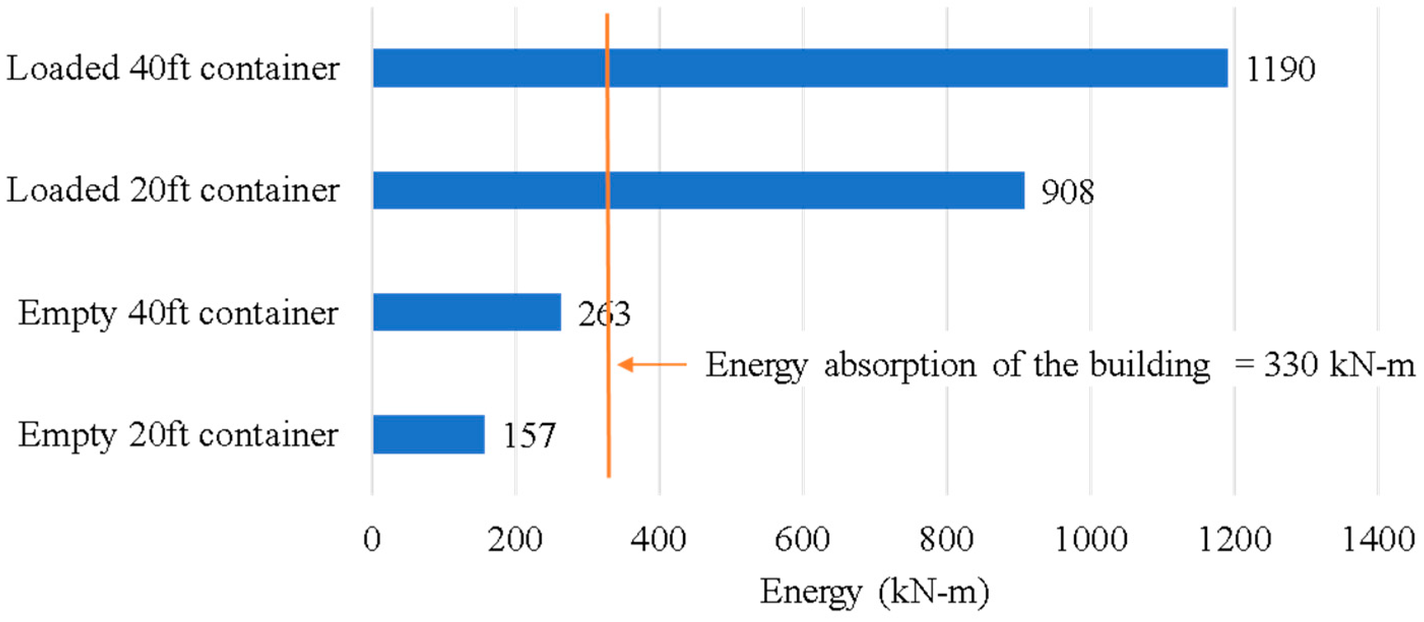
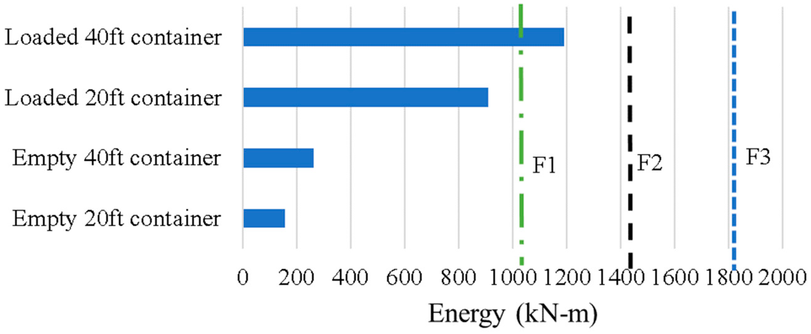
  • The target building was designed on the basis of tsunami forces without debris impact. The analysis showed that the building without a fender could not resist the impact by a loaded shipping container. Therefore, a fender structure was necessary for the target building.
  • The hydrodynamic force on the building with a fender structure was larger than that on the building without a fender structure because the hydrodynamic force on the fender structure was transferred to the main building through the fender. The fender utilized about 30% of its load capacity due to the hydrodynamic force. According to this observation, the design of the building should also consider the hydrodynamic force transferred from the fender structure.
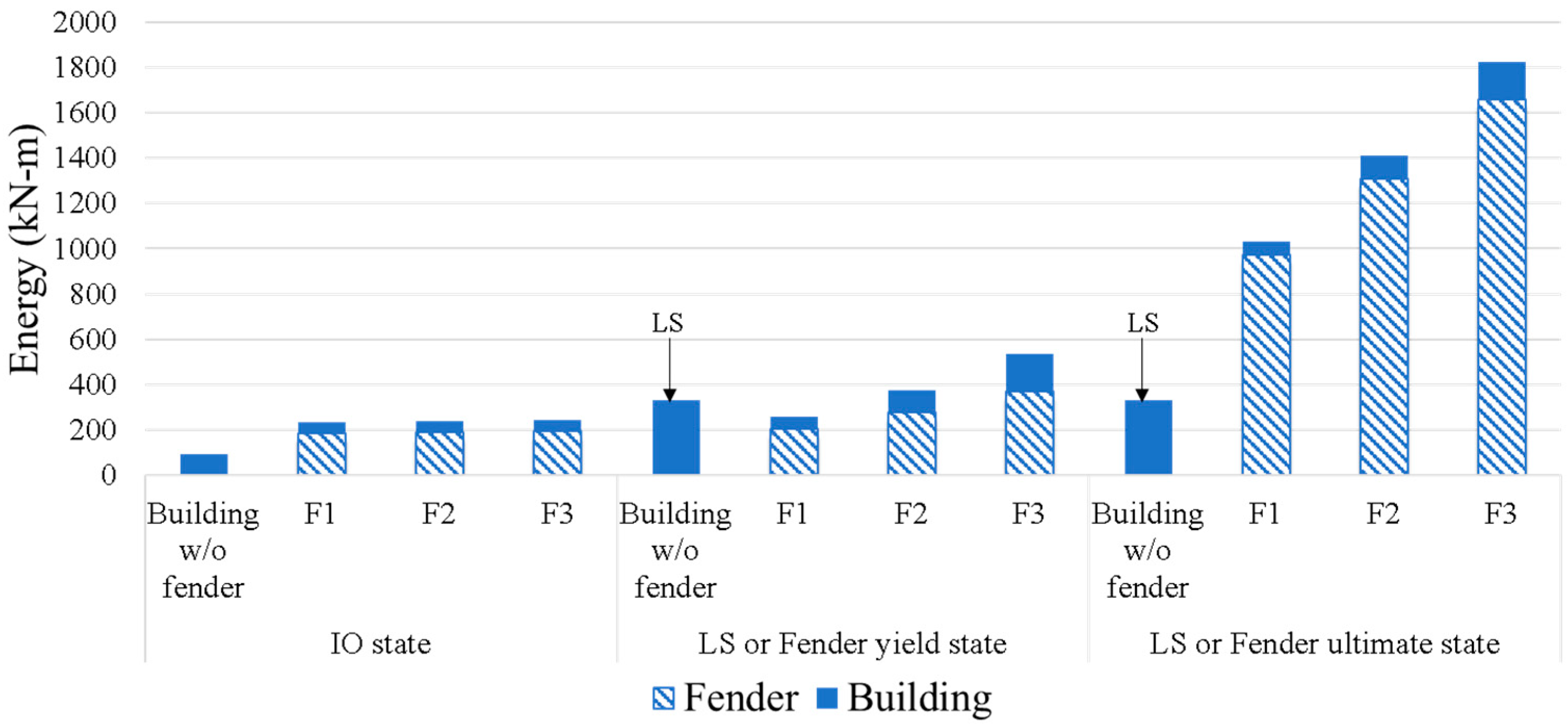
  • In the comparison of the performance of the building with and without fender structures, the building with a fender structure demonstrated limited damage, and the maximum energy was 1800 kN − m, which was able to resist the maximum impact of the shipping container (1190 kN − m). Conversely, the building without a fender structure exhibited severe damage and could not sustain the maximum impact of the shipping container.
  • This study proposed design recommendations for the building with a fender structure. The capacity curve of the building without a fender structure is to be determined first. Then, the kinetic energy of the debris impact is compared with the computed remaining energy absorption of the fender and the building, without the need to perform a nonlinear static analysis of the buildings with a fender structure.

Author Contributions

Conceptualization, Z.Z.T. and A.R.; methodology, Z.Z.T. and A.R.; validation, Z.Z.T. and A.R.; writing—original draft preparation, Z.Z.T., A.R. and Q.H.; writing—review and editing, Z.Z.T., A.R. and Q.H. All authors have read and agreed to the published version of the manuscript.

Funding

This research received no external funding.

Acknowledgments

The authors gratefully acknowledge the Graduate Scholarship Program for ASEAN Countries of Chulalongkorn University for providing the financial support.

Conflicts of Interest

The authors declare no conflict of interest.

References

  1. Lukkunaprasit, P.; Ruangrassamee, A. Building damage in Thailand in the 2004 Indian Ocean tsunami and clues for tsunami-resistant design. IES J. Part A Civ. Struct. Eng. 2007, 1, 17–30. [Google Scholar] [CrossRef]
  2. Triatmadja, R.; Nurhasanah, A. Tsunami force on buildings with openings and protection. J. Earthq. Tsunami 2012, 6, 1250024. [Google Scholar] [CrossRef] [Green Version]
  3. Yeh, H.; Sato, S.; Tajima, Y. The 11 March 2011 East Japan Earthquake and Tsunami: Tsunami Effects on Coastal Infrastructure and Buildings. Pure Appl. Geophys. 2012, 170, 1019–1031. [Google Scholar] [CrossRef]
  4. Naito, C.; Cercone, C.; Riggs, H.R.; Cox, D. Procedure for Site Assessment of the Potential for Tsunami Debris Impact. J. Waterw. Port Coast. Ocean Eng. 2014, 140, 223–232. [Google Scholar] [CrossRef]
  5. American Society of Civil Engineers. Minimum Design Loads and Associated Criteria for Buildings and Other Structures; ASCE7-16; ASCE: Reston, VA, USA, 2016. [Google Scholar]
  6. CCH. The City and Country of Honolulu Building Code; Department of Planning and Permitting of Honolulu: Honolulu, HI, USA, 2000.
  7. FEMA. Coastal Construction Manual: Principles and Practices of Planning, Siting, Designing, Constructing, and Maintaining Residential Buildings in Coastal Areas; FEMA P-55; Federal Emergency Management Agency: Washington, DC, USA, 2011; Volume 2.
  8. FEMA. Guidelines for Design of Structures for Vertical Evacuation from Tsunamis; FEMA P-646; Federal Emergency Management Agency: Washington, DC, USA, 2012.
  9. Chinnarasri, C.; Thanasisathit, N.; Ruangrassamee, A.; Weesakul, S.; Lukkunaprasit, P. The impact of tsunami-induced bores on buildings. Proc. Inst. Civ. Eng. Marit. Eng. 2013, 166, 14–24. [Google Scholar] [CrossRef]
  10. Nouri, Y.; Nistor, I.; Palermo, D.; Cornett, A. Experimental Investigation of Tsunami Impact on Free Standing Structures. Coast. Eng. J. 2010, 52, 43–70. [Google Scholar] [CrossRef]
  11. Arnason, H.; Petroff, C.; Yeh, H. Tsunami Bore Impingement onto a Vertical Column. J. Disaster Res. 2009, 4, 391–403. [Google Scholar] [CrossRef]
  12. Shafiei, S.; Melville, B.; Shamseldin, A. Experimental investigation of tsunami bore impact force and pressure on a square prism. Coast. Eng. 2016, 110, 1–16. [Google Scholar] [CrossRef]
  13. Wüthrich, D.; Pfister, M.; Nistor, I.; Schleiss, A.J. Experimental Study of Tsunami-Like Waves Generated with a Vertical Release Technique on Dry and Wet Beds. J. Waterw. Port Coast. Ocean Eng. 2018, 144, 04018006. [Google Scholar] [CrossRef]
  14. Robertson, I.N.; Paczkowski, K.; Riggs, H.R.; Mohamed, A. Tsunami Bore Forces on Walls. In Proceedings of the ASME 2011 30th International Conference on Ocean, Offshore and Arctic Engineering, Rotterdam, The Netherlands, 19–24 June 2011; pp. 395–403. [Google Scholar]
  15. Lukkunaprasit, P.; Ruangrassamee, A.; Thanasisathit, N. Tsunami loading on buildings with openings. Sci. Tsunami Hazards 2009, 28, 303–310. [Google Scholar]
  16. Hasumi, K.; Ito, K.; Oda, Y.; Honda, T.; Obi, H. A study on fender piles installed around a tsunami evacuation building. In Proceedings of the 25th International Ocean and Polar Engineering Conference, Kona, HI, USA, 21–26 June 2015; pp. 838–845. [Google Scholar]
  17. Pimanmas, A.; Joyklad, P.; Warnitchai, P. Structural design guideline for tsunami evacuation shelter. J. Earthq. Tsunami 2010, 4, 269–284. [Google Scholar] [CrossRef]
  18. BS6349-4; Maritime Structures. Code of Practice for Design of Fendering and Mooring Systems; British Standards Institution: London, UK, 1994.
  19. Hanggara, D.; Wijeyewickrema, A.C. Vulnerability assessment of reinforced concrete buildings in Indonesia subjected to tsunami inundation forces. Int. J. Disaster Resil. Built Environ. 2019, 11, 204–218. [Google Scholar] [CrossRef]
  20. Macabuag, J.; Lloyd, T.; Rossetto, T. Towards the development of a method for generating analytical tsunami fragility functions. In Proceedings of the 2nd European Conference on Earthquake Engineering and Seismology, Istanbul, Turkey, 25–29 August 2014; pp. 25–29. [Google Scholar]
  21. Petrone, C.; Rossetto, T.; Goda, K. Fragility assessment of a RC structure under tsunami actions via nonlinear static and dynamic analyses. Eng. Struct. 2017, 136, 36–53. [Google Scholar] [CrossRef] [Green Version]
  22. Rossetto, T.; De la Barra, C.; Petrone, C.; De la Llera, J.C.; Vásquez, J.; Baiguera, M. Comparative assessment of nonlinear static and dynamic methods for analysing building response under sequential earthquake and tsunami. Earthq. Eng. Struct. Dyn. 2019, 48, 867–887. [Google Scholar] [CrossRef]
  23. ACI Committee. Building Code Requirements for Structural Concrete; ACI318-14; ACI Committee: Farmington Hills, MI, USA, 2014. [Google Scholar]
  24. American Society of Civil Engineers. Seismic Evaluation and Retrofit of Existing Buildings; ASCE/SEI41-17; ASCE: Reston, VA, USA, 2017. [Google Scholar]
  25. Mander, J.B.; Priestley, M.J.; Park, R. Theoretical Stress-Strain Model for Confined Concrete. J. Struct. Eng. 1988, 114, 1804–1826. [Google Scholar] [CrossRef] [Green Version]
  26. Sezen, H.; Moehle, J.P. Shear Strength Model for Lightly Reinforced Concrete Columns. J. Struct. Eng. 2004, 130, 1692–1703. [Google Scholar] [CrossRef]
  27. Aliasghar-Mamaghani, M.; Khaloo, A. Seismic behavior of concrete moment frame reinforced with GFRP bars. Compos. Part B Eng. 2019, 163, 324–338. [Google Scholar] [CrossRef]
  28. Bae, S.; Bayrak, O. Plastic hinge length of reinforced concrete columns. ACI Struct. J. 2009, 106, 233–237. [Google Scholar]
  29. Mortezaei, A.; Ronagh, H.R. Plastic hinge length of reinforced concrete columns subjected to both far-fault and near-fault ground motions having forward directivity. Struct. Des. Tall Spéc. Build. 2013, 22, 903–926. [Google Scholar] [CrossRef]
  30. Priestley, M.J.N.; Park, R. Strength and ductility of concrete bridge columns under seismic loading. ACI Struct. J. 1987, 84, 61–76. [Google Scholar]
  31. Ren, L.; Fang, B.; Wang, K.; Yuan, F. Numerical Investigation on Plastic Hinge Length of Ultra-High Performance Concrete Column under Cyclic Load. J. Earthq. Eng. 2020, 1–19. [Google Scholar] [CrossRef]
  32. Caltrans. Seismic Design Criteria; Version 2.0; California Department of Transportation: Sacramento, CA, USA, 2019. [Google Scholar]
  33. Berry, M.P.; Lehman, D.E.; Lowes, L.N. Appendix: 105-S26 Lumped-Plasticity Models for Performance Simulation of Bridge Columns. ACI Struct. J. 2008, 105, 270–279. [Google Scholar] [CrossRef]
  34. CSI. CSI Analysis Reference Manual; SAP2000; Computers and Structures, Inc.: Berkeley, CA, USA, 2017. [Google Scholar]
  35. PIANC. Guidelines for the Design of Fenders Systems; International Navigation Association: Brussels, Belgium, 2002. [Google Scholar]
Figure 1. Building and fender structure.
Buildings 12 00066 g001
Figure 2. Proposed building (a) three-dimensional, (b) plan, and (c) elevation view.
Buildings 12 00066 g002
Figure 3. Detailed properties of (a) column and (b) beam.
Buildings 12 00066 g003
Figure 4. Moment–rotation relations of plastic hinges.
Buildings 12 00066 g004
Figure 5. Two-dimensional model of the building with a fender structure.
Buildings 12 00066 g005
Figure 6. Detailed properties of steel structure (a) column and (b) beam.
Buildings 12 00066 g006
Figure 7. Load-deformation curve of a typical marine fender.
Buildings 12 00066 g007
Figure 8. Building structures under different cases.
Buildings 12 00066 g008
Figure 9. Deformation of the building and plastic hinge formation for cases Ia and Ib.
Buildings 12 00066 g009
Figure 10. Response of the building without the fender structure. (a) Capacity curve due to hydrodynamic force and debris impact, and (b) relationship between energy absorption and displacement at the debris impact floor.
Buildings 12 00066 g010
Figure 11. Inter-story drift ratio due to debris for cases Ia and Ib.
Buildings 12 00066 g011
Figure 12. Comparison of energy absorption of the building for cases Ia and Ib.
Buildings 12 00066 g012
Figure 13. Idealized force–deformation relation of the fenders.
Buildings 12 00066 g013
Figure 14. Load-deformation relations of fenders at various states: (a) Fender F1, (b) Fender F2, and (c) Fender F3.
Buildings 12 00066 g014
Figure 15. Capacity curve due to debris impact after applying hydrodynamic force: (a) building with fender F1, (b) building with fender F2, and (c) building with fender F3.
Buildings 12 00066 g015
Figure 16. Plastic hinge formation of the building with the fender structure.
Buildings 12 00066 g016
Figure 17. Inter-story drift ratios of the buildings.
Buildings 12 00066 g017
Figure 18. Energy absorption of the buildings with and without the fender structure.
Buildings 12 00066 g018
Figure 19. Energy absorption compared with the energy from shipping container impacts.
Buildings 12 00066 g019
Figure 20. Flowchart of the proposed recommendation for the building with a fender structure.
Buildings 12 00066 g020
Figure 21. Idealization of the building without a fender structure.
Buildings 12 00066 g021
Figure 22. Idealization of the building with a fender structure.
Buildings 12 00066 g022
Figure 23. Target performance based on the selected fender yield force.
Buildings 12 00066 g023
Table 1. Structural properties of the building.
ComponentStructural Properties
ColumnsCross-section (mm)850 mm diameter
Deformed bar size (mm)28 mm
Transverse bar size (mm)16 mm
Nos of longitudinal bar28
Rebar percentage3.06%
Stirrup spacing100 mm
PMM interaction ratio0.859
BeamsCross-section (mm)400 × 600 mm
Deformed bar size (mm)25 mm
Transverse bar size (mm)12 mm
Nos of longitudinal bar8
Rebar percentage1.64%
Stirrup spacing280 mm
PMM interaction ratio0.744
SlabThickness (mm)200 mm
Table 2. Parameters for the fender structure.
ParametersValues
Fender reactionBased on LS state of the building
(to be varied)
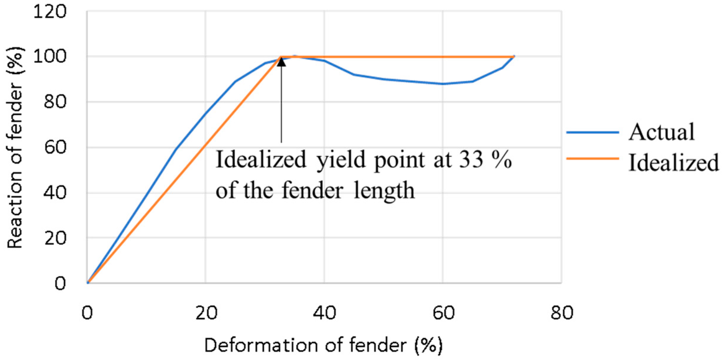
Fender deformation at yielding33% of fender length
Fender deformation at ultimate point72% of fender length
Table 3. Parameters of tsunami loads.
ParametersValues
Design inundation depth, h9 m
Velocity coefficient, α 1.25
Acceleration due to gravity, g9.81 m/s2
Flow velocity, u11.75 m/s
Drag coefficient, Cd (ASCE 7-16)1.2 (for circular element)
2 (for rectangular element)
Minimum fluid density for tsunami load, ρ1128 kg/m3
Mass of 20 ft standard shipping container
(ASCE 7-16, FEMAP 646)
2270 kg (empty)
13,150 kg (loaded)
Mass of 40 ft standard shipping container
(ASCE 7-16, FEMAP 646)
3810 kg (empty)
17,240 kg (loaded)
Table 4. Parameters of the fenders.
CaseActual Fender PropertiesIdealized Fender Properties
Fender Length, Lf (m)Stiffness (kN/m)Maximum Reaction (kN)Idealized Stiffness (kN/m)Idealized Yield Force (kN)
F11.63796201237002000
F21.83735220437002200
F323589236937002400
Publisher’s Note: MDPI stays neutral with regard to jurisdictional claims in published maps and institutional affiliations.

