Article

Informed Finite Element Modelling for Wire and Arc Additively Manufactured Metallics—A Case Study on Modular Building Connections

by
Madhushan Dissanayake
1,
Thadshajini Suntharalingam
1,
Konstantinos Daniel Tsavdaridis
2,3,*,
Keerthan Poologanathan
1 and
Gatheeshgar Perampalam
1
1
Department of Mechanical and Construction Engineering, Faculty of Engineering and Environment, Northumbria University, Newcastle upon Tyne NE1 8ST, UK
2
School of Civil Engineering, Faculty of Engineering and Physical Sciences, University of Leeds, Leeds LS2 9JT, UK
3
Department of Civil Engineering, School of Mathematics, Computer Science and Engineering, University of London, London EC1V 0HB, UK
*
Author to whom correspondence should be addressed.
Buildings 2022, 12(1), 5; https://doi.org/10.3390/buildings12010005
Submission received: 24 November 2021 / Revised: 15 December 2021 / Accepted: 19 December 2021 / Published: 22 December 2021
(This article belongs to the Section Building Structures)

Abstract

:
The use of 3D printing in modular building connections is a novel and promising technique. However, the performance of 3D printed steel modular building connections has not been investigated adequately to date. Therefore, this paper presents a three-dimensional finite element model (FEM), using the multi-purpose software Abaqus, to study the effect of different geometrical and material parameters on the ultimate behaviour of modular building connections (herein named 3DMBC) using a wire and arc additive manufacturing (WAAM) method, as part of the UK’s 3DMBC (3D Modular Building Connections) project. The proposed model considers material and geometrical non-linearities, initial imperfections, and the contact between adjacent surfaces. The finite element results are compared with the currently available experimental results and validated to ensure developed FEM can be used to analyse the behaviour of 3DMBC with some adjustments. Case studies were investigated using the validated model to analyse the ultimate behaviour with different nominal and WAAM-produced materials under various loading arrangements. Based on the results, it is recommended to conservatively use the treated or untreated WAAM material properties obtained in θ = 90° print orientation in the finite element modelling of 3DMBCs considering the complex component arrangements and multi-directional loading in the modular connections. It is also noted that the thickness of beams and columns of fully 3D printed connections can be increased to achieve the same level of performance as traditional modular connections. For the 3DMBCs printed using untreated WAAM, the thickness increment was found to be 50% in this study.

1. Introduction

Off-site modular construction is gaining increased interest in urban areas, where building construction procedures are often challenging due to limited workspace and high standards for minimum disruption during construction [1]. This prefabricated building construction method increases construction productivity by performing a large proportion of the work that is traditionally done on-site at production yards or factories [1,2]. A Modular Building Structure or System (MBS) is an integrated structure in which the whole frame or building contains prefabricated room-sized volumetric modules or structural units fabricated off-site and then installed on-site [2,3]. This modular construction method offers several advantages such as increased construction speed, reduced construction cost and material waste, enhanced quality control, and minimal environmental impacts [1,2,3,4].
Inter-modular connections are used to connect the individual modules in multi-story modular buildings to create a functioning structure. These connections are a crucial part of off-site construction and play a prominent role in providing performance and integrity to modular buildings [1,3,5]. Hence, the ability of modular buildings to resist external loads is greatly influenced by inter-module connections [3,6,7,8]. The inter-modular connection must be designed to provide effective load paths between adjacent modules and simple on-site assembly. Ideally, seamless dismantling is also required in order to reuse the modules and their components. Recently, researchers have proposed numerous novel modular connections that are intended to increase structural integrity.
In recent decades, the potential of additive manufacturing, which is also known as 3D printing, has progressed significantly, offering efficient construction methods and providing optimised structural solutions [9,10,11]. The term 3D printing refers to the technique of depositing successive layers of materials such as plastic, resin, rubber, ceramic, glass, concrete, and metal upon each other, producing a final three-dimensional object. Unlike conventional manufacturing methods for construction products, metal 3D printing offers multiple opportunities to create complex geometries, internal stiffening, openings, functionally graded elements, variable microstructures, and mechanical properties through controlled heating and cooling and thermally induced prestressing [10,12,13,14]. It is expected that the associated costs and time of additive manufacturing will drop rapidly in the next few years with the advancement of this technology. The 3D printing method can produce customised and very complex components at a low cost compared to traditional manufacturing techniques, as traditional methods require mass production to lower the cost of a unit [15]. Several printing methods have been identified to date, such as Powder Bed Fusion (PBF), Directed Energy Deposition (DED) and sheet lamination [16]. Among them, DED, and in particular, Wire and Arc Additive Manufacturing (WAAM) technology, is identified as the more flexible method because it allows the development of structural components without theoretical dimensional constraints [15,16,17]. In addition, stainless steel is becoming more popular in the construction industry due to its advantages such as weldability, corrosion resistance, reduced inspection frequency, maintenance, downtime and replacement costs, and a transition towards sustainability.
Laghi et al. [16] experimentally investigated the structural design of WAAM stainless steel members, including the geometrical and mechanical properties. The results showed that the material properties of 3D printed specimens were influenced by geometrical irregularities due to the WAAM process. Al-Nabulsi et al. [18] studied the mechanical properties of WAAM 3D printing of steel in structural engineering and found that the mechanical properties of the WAAM steel satisfied the requirements for structural steel grades used for building structures as specified by Eurocode 3 (EN 1993–1-1). Kyvelou et al. [19] performed mechanical and microstructural testing of WAAM sheet materials and defined effective mechanical properties for as-built material based on simple geometrical measures. Gardner et al. [17] tested and verified a 3D printed stainless steel bridge constructed by the Dutch company MX3D using the WAAM technique, which included advanced geometric analysis, material testing, compressive testing of cross-sections, and full-scale load testing of the bridge at various stages throughout and post-construction.
Furthermore, Camacho et al. [20] proposed some small-scale 3D printed fastener-free connections using a polylactic acid (PLA) material motivated by traditional wood joinery to be used in structural or non-structural applications. Lange and Feucht [21,22] proposed topology-optimised connecting structures which can be printed with the WAAM directly on steel beams (shown in Figure 1). In addition, a number of studies have investigated the mechanical behaviour and strength of 3D printed polymer components [23,24]. However, there is an evident absence in the investigation of the structural performance of 3D printed steel modular building connections (herein named 3DMBC) using the WAAM method. The investigation into WAAM-based connections will allow it to be used in modular buildings with greater understanding. Therefore, the aim of this study is to provide informed modelling decisions for 3DMBCs. Hence, this study focused on developing and proposing a general three-dimensional FE model for stainless steel 3DMBC using WAAM including initial imperfections, local buckling, and modelling the contact between different surfaces as well as comparing the results with those of available experiments results. In this study, two individual validations were performed for the modular steel connection and the 3D printed stainless steel stub columns using the WAAM method. Then, the study was extended to develop a combined numerical model to simulate the structural performance of 3D printed stainless steel modular connections manufactured using the WAAM method.

2. Background

2.1. Modular Buildings and Inter-Modular Connections

Standard inter-module connections consist of plates connected using bolts or welds, which require particular space to facilitate bolting or welding [25]. Inter-modular connections entail horizontal connections in two plane directions from neighbouring modules and a vertical connection within stacked modules. In general, for on-site constructions, bolted connections are favoured over welded joints. A space between the floor and ceiling frames is generally provided, facilitating external access to inter-module connections and the provision of facilities between beams. Consequently, here the focus is on the connection between the columns rather than the beams. Inter-modular connections provide a path for load sharing and transfer between modular units, which are, effectively, the linked structural parts that allow stacked modules to transfer loads all the way down to the foundation. The interconnections fulfil robustness requirements through load sharing, mitigating the danger of catastrophic incremental collapse due to local failure. Furthermore, individual designs of frame members may demand lateral restraint created by a link between the modules. Interconnections also meet the requirements of construction and serviceability. An interconnection can, for example, be used to bring modules together during site assembly to close the distance between them, thereby enabling individual modular units that are not perfectly straight or square to be used. Interconnections also restrict the differential movement between modules that can otherwise degrade the flashing or cause serviceability failure [8].

2.2. Metal 3D Printing and Limitations of WAAM

Metal 3D printing technology can enhance the resource efficiency of the Architecture, Engineering, and Construction (AEC) industries by eliminating geometrical complexity. A promising breakthrough for metal AM technology is the Wire and Arc Additive Manufacture (WAAM) process which combines electric arc welding techniques with wire feeding [17]. A key objective of WAAM is to reduce waste material produced during manufacturing [26,27]. The WAAM system allows the production of large custom-made and low volume metal workpieces with high deposition rates. The most challenging concerns that arise from the WAAM process are geometric distortions due to non-uniform expansion and contraction of the material during thermal cycles, resulting in large and anisotropic residual stresses [14]. Therefore, it is important to understand the thermomechanical performance during the WAAM process and improve the WAAM process to reduce the residual stress and distortion level. Although these thermally induced issues are unavoidable for the WAAM process, using careful deposition parameters and build paths can control the residual stresses and minimise the distortion level. Hence, Ding et al. [27] investigated the thermo-mechanical analysis of the WAAM process using the FE analysis. Furthermore, Kyvelou et al. [19] assessed the influence of the as-built geometry on the mechanical response, and tensile coupon tests were performed on both the as-built and machined material.

3. Finite Element (FE) Modelling of Modular Connections

3.1. General

A 3-dimensional finite element model (FEM) was developed for a modular building connection as part of the 3DMBC project (www.3dmbc.com, accessed on 24 November 2021), using Abaqus software to investigate the characteristics of 3D printed stainless steel connections and the factors affecting their behaviour in order to predict their structural behaviour and failure mechanisms under working loads.
Chen et al. [28] conducted laboratory experiments on modular building connections, and one of these connections was considered in this study. The simulated connection consists of two stiffened upper and lower parts, three long-stay bolts, and a plug-in device to resist the vertical and horizon movements at the connection. The cold-formed rectangular hollow beams and columns were groove welded, and two diagonal stiffeners were fillet welded to the beams and columns. A cover plate was welded to the top flange of the upper beam, while an intermediate plate and a bottom cover plate were welded to the top and bottom flanges of the lower beam, respectively, at the stay-bolted connection. The plug-in device was inserted into the upper end of the lower column and the lower end of the upper column. All the units, including beams, columns, plates, and bolts, were made from Q345B steel grade, while the plug-in device was made from ZG35 cast steel according to Chinese standards. The dimensions of all the units and the material properties can be found in Chen et al. [28]. The lower end of the lower column was pinned to allow the rotation, and the two beam ends were placed between rollers so they could rotate and move independently from each other. The upper end of the upper column was assumed to have a free end where the loading was applied. A vertical load of 286.3 kN was given to the top column end prior to the lateral loading of the connection and maintained during the rest of the test to simulate axial load. A monotonic horizontal loading at the upper column end was applied to study the response of the modular connection in the experiment. Suitable assumptions were made during the FE model development to simulate the real response of the connection as accurately as possible. The following components were modelled together as a single unit in the FE modelling: (1) upper beam, upper column, top cover plate, and upper diagonal stiffener; (2) lower beam, lower column, intermediate plate, bottom cover plate, and lower diagonal stiffener; (3) plug-in plate and tubes; and (4) bolts, bolt heads, and nuts. First, each component was created as a separate part in Abaqus. Then, the corresponding components were merged using the merge instances option to create the four units mentioned above. After that, each unit was meshed separately using an adaptive mesh. When modelling bolts, threads, and holes, tolerances were neglected. The details of the modelling techniques used are discussed in the following section.

3.2. FE Mesh

For this simulation, 8-node first-order hexagonal elements with incompatible mode (C3D8I) were employed to model each steel plate component in the modular connection. The C3D8I elements can eliminate shear locking and perform better in bending compared to 8-node first-order hexagonal elements with reduced integration technique (C3D8R) [29,30]. The sweep meshing technique with medial axis algorithm was used for the bolted regions, whereas the structured meshing technique was adopted in the other regions. A finer mesh was employed in the regions near the beam–column connection and bolts, while a relatively larger mesh size was used for the other regions. Therefore, the mesh size was 10 mm near the connection and 30 mm in the outer beam and column regions. Bolts were meshed using a 2 mm mesh, while bolt holes were meshed with 32 elements along the circumference to define the geometry accurately. Figure 2 illustrates the different mesh sizes employed in the FE model.

3.3. Material Model

The stress–strain response of cold-formed steel was represented using a bi-linear material model with strain hardening in the numerical modelling. Material properties were extracted from Chen et al. [28]. Young’s modulus and Poisson’s ratio were defined under elastic properties. The experimental stress and strain values were first converted into the true stress and the log plastic strain data and then input into Abaqus under plastic properties.

3.4. Contact Interactions

Contact interactions in Abaqus define how two components move when they are in contact and do not allow them to overlap. To model the contact between two interacting surfaces, surface-to-surface (standard) contact interactions were used. The tangential behaviour of the interactions was simulated using penalty friction formulation with a suitable friction coefficient. The penalty friction formulation models the slip, and the friction coefficient defines the friction between contact surfaces. The normal behaviour of the interactions was defined as ‘hard contact’. Hard contact shares the pressure between two surfaces only if they are in contact. Moreover, the tangential interaction between bolt shanks and bolt holes was assumed to be frictionless, while a friction coefficient of 0.3 was assigned for all the other surfaces. When defining contact interactions, bolt shanks were considered master surfaces.

3.5. Loading and Boundary Conditions

The outer ends of columns were tied to reference points when defining boundary conditions. All three translational degrees of freedom (DOFs) were restrained at the bottom end of the lower column to simulate a pin support, allowing in-plane rotations of the connection. The upper column end was a free end. The vertical movement was restrained at the two beam ends to simulate roller support conditions. The pretension force of the bolts was calculated from Equation (1) in Khan and Yan [31] and was simulated using the bolt load option in Abaqus. A bolt preload equivalent to 38.6 kN was assigned to each bolt shank during the first analysis step; then, the load was fixed at the current length in the next step and maintained throughout the subsequent steps. An axial load of 286.3 kN, which is the 0.2 of column compressive strength, was applied and maintained at the column’s top before applying a static 100 mm lateral displacement to the top end of the column in the last analysis step.

3.6. Analysis

A static, general analysis considering geometric and material non-linearity was performed on the developed FE model of the modular connection. The analysis comprised four steps. The FE results were examined in terms of load-deflection curves, failure behaviours, and von Mises stress contours to study the structural response of the connection. Additionally, a cyclic loading can easily be applied to the developed FEM to investigate the seismic behaviour of the 3DMBCs. However, this was not addressed in the current study.

3.7. Validation of the Model

For validation, the FE model of the modular building connection was compared to the experimental results of Chen et al. [28]. Figure 3 compares the experimental lateral load-deflection curve with the FE curve. It can be seen that the FE curve closely predicts the initial stiffness and load-deflection response of the tested modular connection with some minor deviations, which may be attributed to the variation of material properties, cross-sections, and boundary conditions in the experiments, or could also be a result of assumptions made during the FE modelling. The ultimate lateral load was recorded to be 199.4 kN at an approximate lateral displacement of 91 mm in the test, and the corresponding FE load was found to be 200.1 kN. Therefore, the experimental FE ultimate load ratio can be taken as equal to 1.00, which suggests a good agreement between results.
The experimental and FE deformed shapes of the connection are compared in Figure 4, which demonstrates that the FE model predicts the behaviour of the modular connection well. During the test, a weld fracture was observed in the specimen at the failure point, while the stress concentration areas corresponding to weld fracture can be clearly seen in the FE model in the vicinity of the weld.

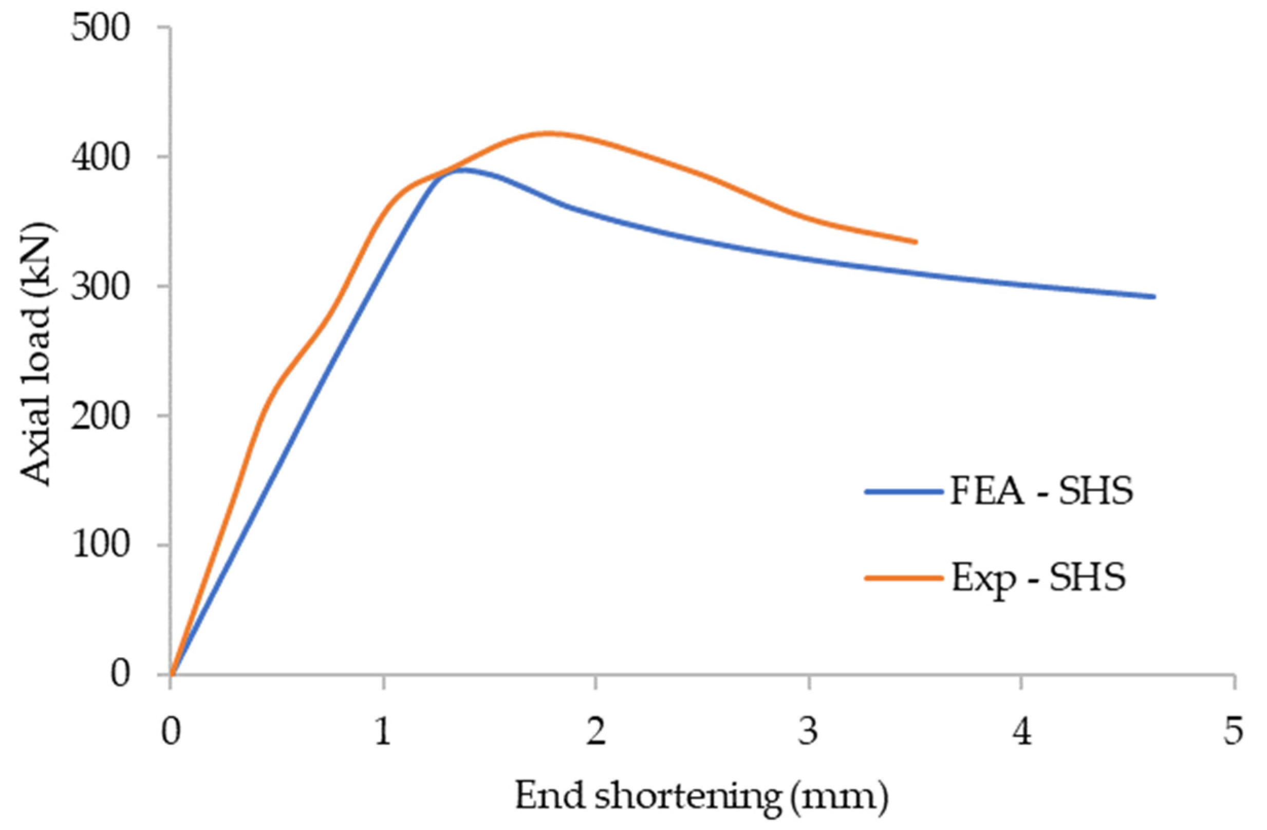
4. FE Modelling of WAAM Stainless Steel Behaviour

4.1. Model Development
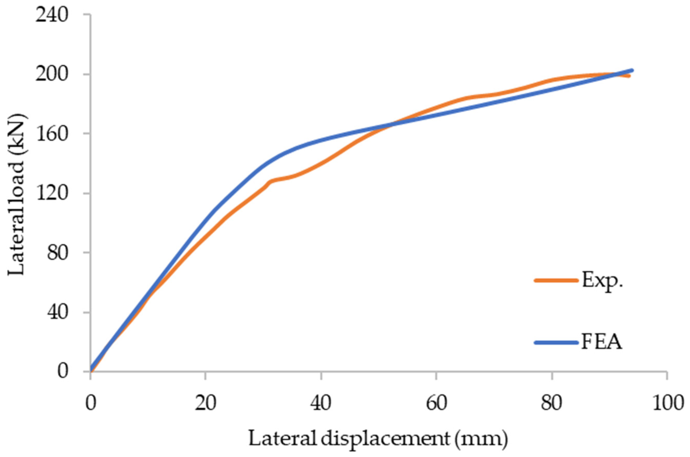
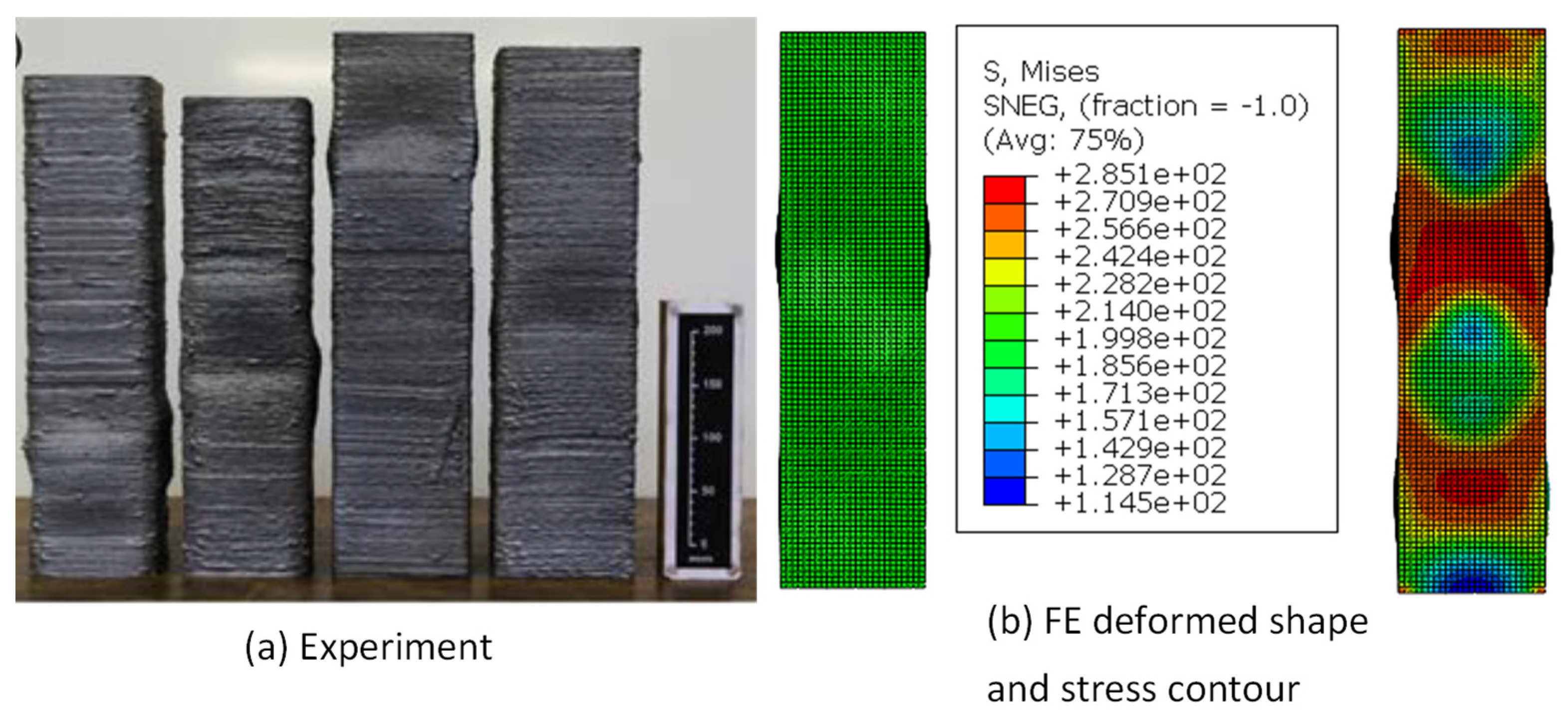
An in-depth numerical analysis was conducted to investigate the structural behaviour of sections made of WAAM stainless steel. A FE model of a 3D printed stub column was first simulated in Abaqus and then validated against the experimental results. The FE model was based on experiments reported by Gardner et al. [17] on compression tests of WAAM stub columns. The columns were printed from austenitic stainless-steel grade 308LSi. The material properties of both machined and as-built tensile coupons have been recorded in the study for three coupon orientations compared to printing direction (i.e., parallel, diagonal, and normal). Both square and circular hollow sections were tested in the experiments, while one square hollow section was considered for the FE modelling. The stub column ends were attached to end platens, and the bottom end was fixed while the top end was allowed to move vertically. Axial loading was applied to the top end, and the load-deflection responses, ultimate loads, and failure behaviours were provided by Gardner et al. [17].
In the FE modelling, a 4-node shell element with reduced integration (S4R) was adopted to simulate the hollow section. A refined mesh size of 5 mm was chosen considering both the accuracy and the computational cost. The material properties corresponding to as-built WAAM tensile coupons in the normal direction (θ = 90°) were extracted from Gardner et al. [17] and used in the numerical modelling. The non-linear stress–strain behaviour, including strain hardening of stainless steel, was simulated from the two-stage Ramberg–Osgood material model [32,33]. Then, the corresponding true stress and plastic strain values were calculated for the stress–strain response of WAAM stainless steel before inputting material data into Abaqus. When defining boundary conditions, the stub column ends were coupled to reference nodes, and all the DOFs were restrained except the vertical translations at the top end to model fixed end conditions. The axial load was simulated using a vertical displacement control load at the top end. Then, the developed FE model was analysed to study the compression response of the WAAM stub column.
First, an elastic buckling analysis was conducted on the FE model, and the critical buckling mode of the stub column was identified. That mode was then introduced to the non-linear analysis to account for local geometric imperfections. A scale factor equal to 10% of the section thickness was employed in the non-linear analysis as the imperfection amplitude. Then, geometrical and material non-linear analysis was performed on the FE model using the Static, General method. The FE results are compared against the experimental results in the next section.

4.2. Validation

The performance of the FE model in terms of load-deflection curves, ultimate loads, and failure patterns was compared with the experimental results reported in [17]. Figure 5 compares the test and FE axial load-end shortening curves. The comparison shows good agreement between the two curves. The minor deviations between the two curves could be a result of varying material properties with the wall thickness and uneven cross-section geometry of the WAAM specimen. The experimental ultimate axial load of the specimen was recorded to be 414.5 kN, and that of the FE model was found to be 387 kN. Therefore, the experimental to FE ultimate load ratio can be taken as 1.07. This ratio suggests that the FE model predicts the ultimate load of the WAAM stub column well.
The experimental and FE failure modes are compared in Figure 6, which also demonstrates good agreement. The local buckling failure pattern of the WAAM stub column is well captured by the FE model. Therefore, it can be concluded that the developed FE model can accurately simulate the structural response of WAAM stainless steel stub columns under compression in terms of initial stiffness, ultimate load, and failure behaviour.

5. Assessment of the 3D Printed Stainless Steel Modular Connection

5.1. General

In this section, the performance of the 3D printed stainless steel modular connection is examined as a practical example for the steel industry. As reported in the previous section, the successful validation of the modular steel connection and the 3D printed stainless steel stub columns using the WAAM method were performed. These two validations ensured the ability of the developed numerical models to simulate the structural response of the modular connection made of steel and the material behaviour of 3D printed stainless using the WAAM method, respectively. These two numerical modelling approaches were combined to develop the 3D printed stainless steel modular connection using the WAAM method. To elaborate, the material properties for the 3D printed stainless steel product using the WAAM method were introduced in the developed numerical model of modular steel connection to replicate the 3D printed modular connection using the WAAM method.

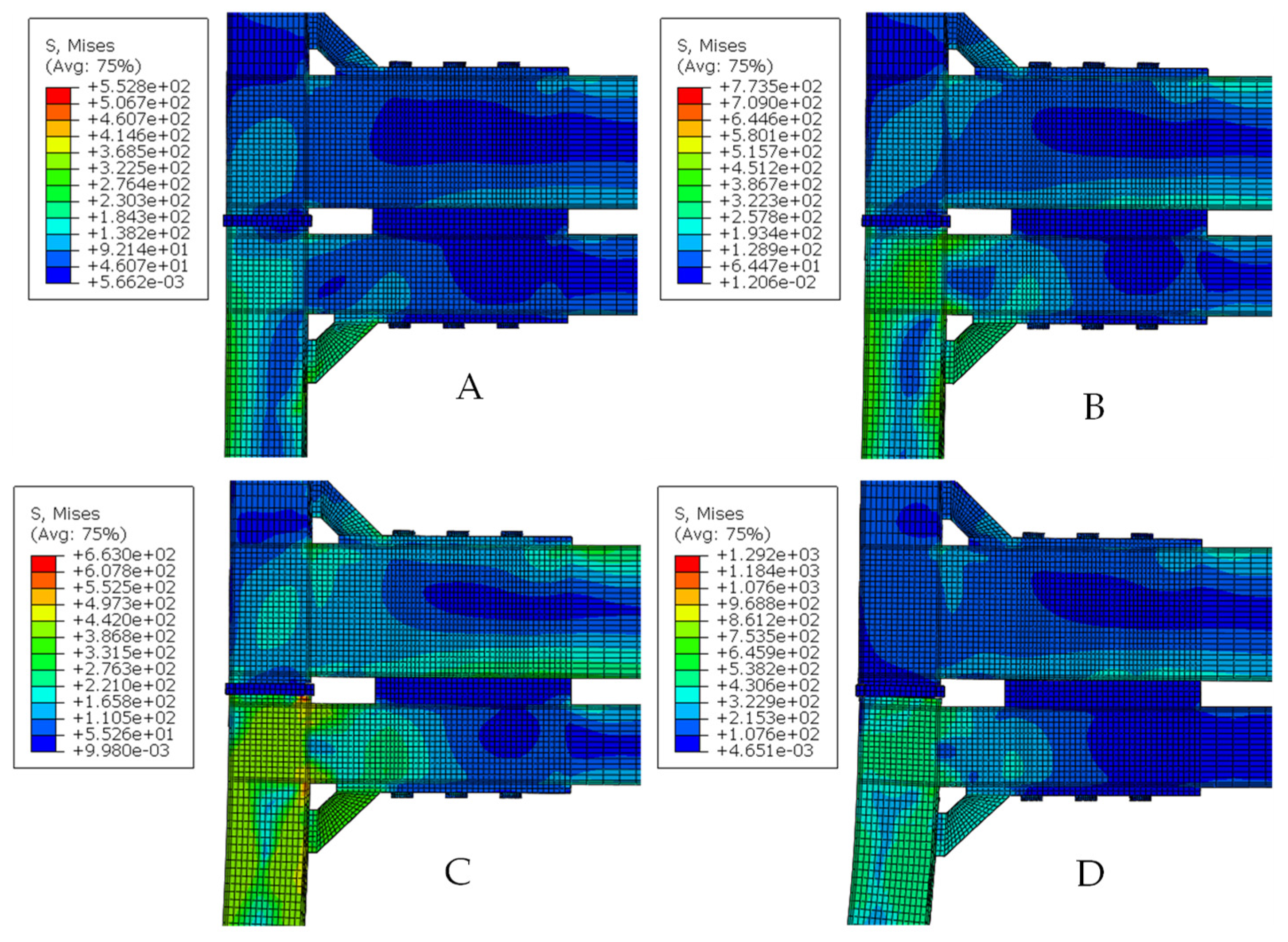
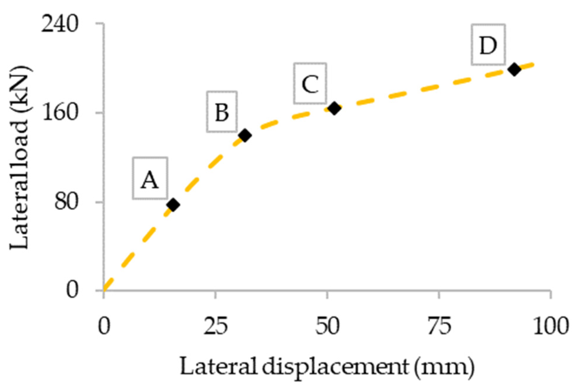
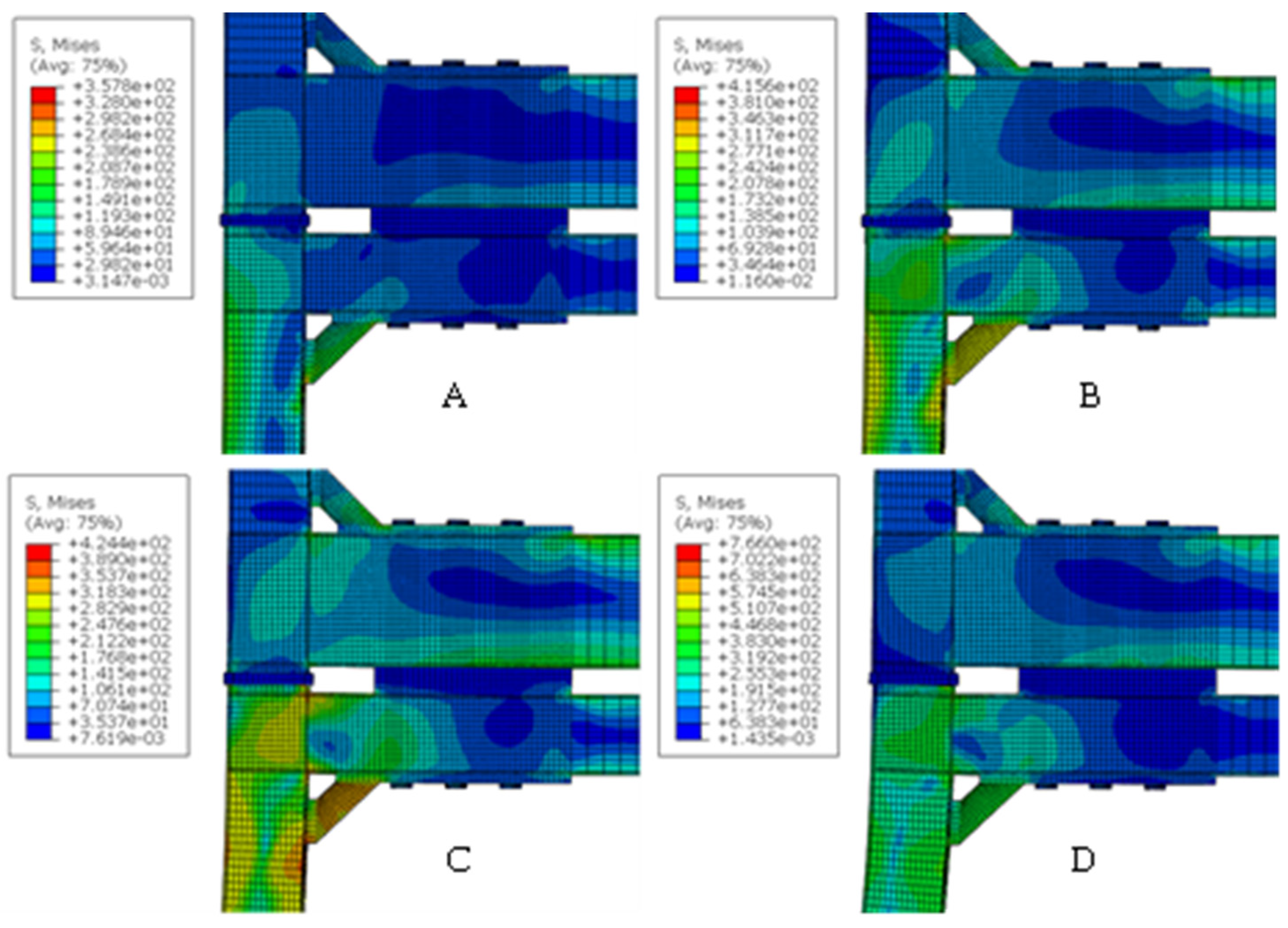
5.2. Results and Discussion

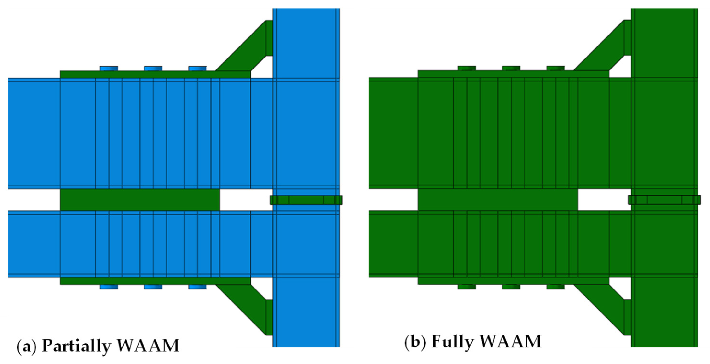
5.2.1. 3D Printed Connection with Untreated WAAM Surfaces and Equivalent Thickness Approach

The measured material properties of 3D printed stainless steel products using the WAAM method reported [17] were adopted. The material properties were associated with the orientation of the layer direction in the extracted tensile coupons. A notable anisotropy behaviour of the material response has been observed depending on the orientation of the layer direction. Among the tested direction (θ) of 0°, 45°, and 90°, the coupon tested with θ = 90° orientation showed the overall lowest strength properties in terms of yield strength, ultimate strength, and elastic modulus. Therefore, aiming for a conservative approach, the WAAM stainless steel material properties measured in the θ = 90° orientation were employed in the benchmark analysis of the connection. Table 1 summarises the adopted key material properties in this study. In Table 1, fy is the yield strength, fu is the ultimate strength, E is Young’s modulus, εu is the ultimate strain, and n and m are strain-hardening exponents of stainless steel.
Further, the structural response of the modular connection was approached in two ways: (a) assuming the entire modular connection is printed using WAAM—Fully WAAM; (b) assuming a hybrid modular connection with partially printed (only the selected components) using WAAM—Partially WAAM. For the latter approach, the components of the plug-in connection, cover-plate for floor beam, inter-plate between beams, cover-plate at ceiling beam, and stiffener were assumed to be printed using WAAM (see Figure 7).
Figure 8 depicts the lateral load against lateral displacement response of the modular connection for these two approaches. The experimental curve is also included in the same plot in order to give a reference, irrespective of the different yield strengths of the conventional steel modular connection and WAAM products. From Figure 8, it can be noticed that replacing the selected components marginally influences the structural response of the connection compared to the existing modular steel connection, irrespective of the lower yield strengths of the WAAM products. This could be due to the fact that the components selected to represent the 3D printed parts do not significantly contribute to the performance of the modular connection, though these components are essential for the modular connection to act as an entire unit. However, when the entire modular connection is 3D printed using WAAM (the second approach), a noticeably lower structural performance was noticed compared to the reference modular steel connection and the partial WAAM modular connection in terms of load-bearing capacity and the initial stiffness. This may be due to the inherent lower strength properties of the considered 3D printed product using WAAM compared to that of the components in the reference modular connection. Figure 9 and Figure 10 illustrate the progressive responses of partially and fully WAAM 3DMBCs under lateral loading, respectively. The relatively higher rotation of the lower column can be seen in the response of both connections, which consequently leads to the failure of the connection.
For the fully WAAM modular connection, further analysis was conducted to investigate the possibility of improving the strength of the 3D printed modular connection to reach a strength similar to the reference modular connection even with the lower mechanical properties of the considered WAAM product with θ = 90° orientation. As a potential approach, the thickness of the columns and beams was increased progressively to determine the equivalent WAAM thickness that provides the same performance as a conventional modular connection. The thickness of the columns and beams in the connection was increased from 8 mm to 12 mm in increments of 2 mm. Figure 11 shows the obtained lateral load against lateral displacement behaviours for these cases. From the results, it can be noticed that for the considered modular connection, 12 mm equivalent untreated thickness is required to match the performance of the reference modular connection. Thus, for the particular modular connection considered in this study, a 50% thickness increment is required for the WAAM beam and column to capture a similar structural response.

5.2.2. 3D Printed Connection with Treated WAAM Surfaces

This section investigates the structural performance of the 3D printed modular connection with treated WAMM surfaces, as the past research study [17] observed a noticeable variation in the material properties of the same WAAM product with treated and untreated surfaces, along with the print orientation. For this analysis, the reference modular connection model was created with the material properties of austenitic stainless steel grade 308LSi (included in Table 1). For the 3D printed modular connection, the material properties reported in [17] for the treated WAAM product measured in three orientations (θ = 0°, 45°, and 90°) were employed. The material properties are also given in Table 1. It should be noted that the material properties of the traditionally manufactured 308LSi stainless steel and the treated WAAM coupons diagonal to the print orientation (θ = 45°) are approximately the same. This led to a detailed comparison between the conventional and 3D printed modular connections, as the material properties are approximately the same. Figure 12 displays the lateral load against displacement responses obtained for the 3D printed modular connections with treated WAAM surfaces and the reference modular connection. The results show that the 3D printed modular connection considered in θ = 45° print orientation yielded approximately the same structural behaviour compared to the reference modular connection. However, 3D printed modular connections with θ = 0° and θ = 90° print orientations resulted in comparatively lower structural performance compared to the reference modular connection and the 3D printed modular connection with θ = 45° print orientation.
Even though the 3D printed connection with θ = 45° print orientation shows higher structural performance, it should be noted that in practice, all the components in the modular connection cannot be printed with θ = 45° print orientation. Therefore, based on the observed results, it is recommended to consider the material properties of the treated WAAM product obtained in θ = 90° print orientation, which is a conservative approach to evaluate the structural performance through numerical modelling.

5.3. Recommendations for FE Modelling and Design of 3DMBCs

Based on the findings of the numerical case studies conducted in this paper, the following design and manufacturing recommendations can be made with regard to the FE modelling and design of 3DMBCs:
  • Components such as cover plates and stiffeners, which are relatively thicker and smaller in size, can be 3D printed without altering the performance of the modular connections. Alternatively, if not required, these components should not be 3D printed due to the increase in the total cost of the connection’s manufacture.
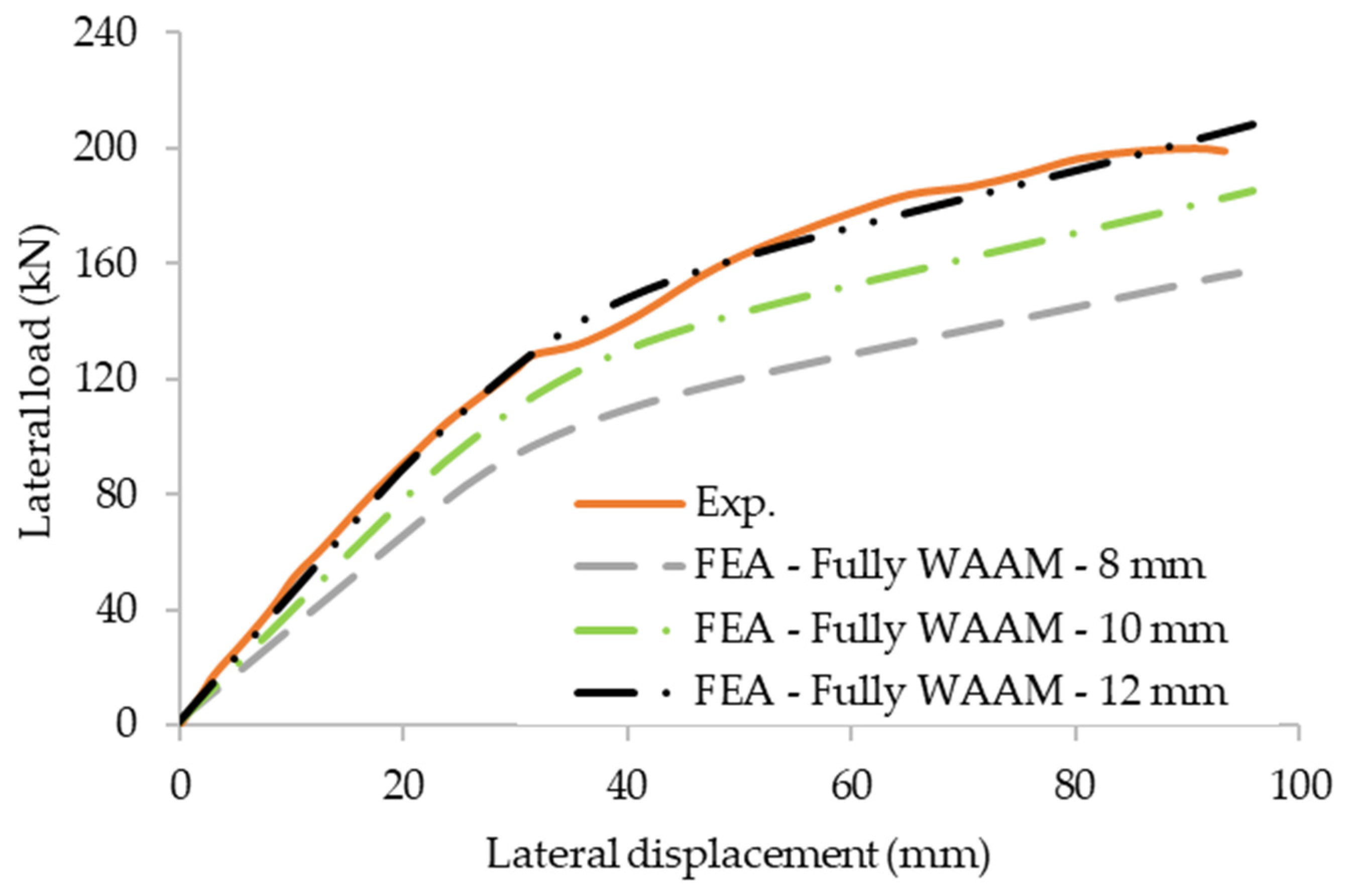
  • Increasing the thickness of beams and columns of the fully 3D printed connection is recommended to achieve the same level of strength as the normal connection.
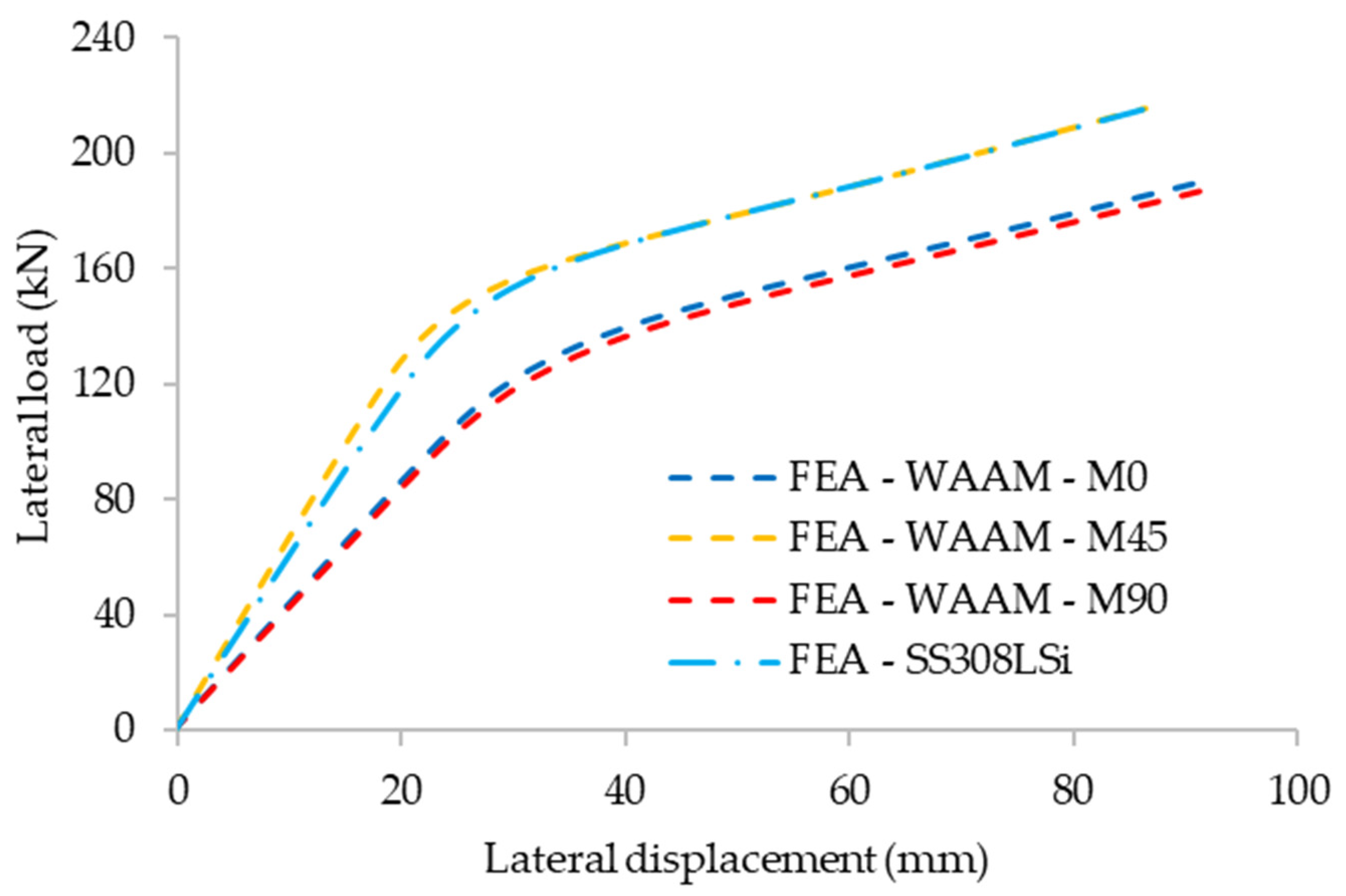
  • Untreated or treated WAAM material properties corresponding to θ = 90° orientation can be used in the FE modelling of 3DMBCs to obtain conservative results.

6. Concluding Remarks

3D printing is a rapidly evolving technology that provides greater opportunities and geometrical freedom while having the potential to utilise innovative materials. This technology could be employed extensively for the advancement of complex and flexible structural systems such as connections, in particular, those used in modular construction. The WAAM method has been proven to be a viable and cost-effective 3D printing technique as it can produce medium to large structural components due to its high-rate deposition and theoretically unrestricted build size. WAAM can also be highly beneficial for refurbishing structural components by adding parts (e.g., stiffeners, plates, clamps, etc.) to normal steel members when considering reuse. Hence, the aim of this study is to build the interlink and propose informed-modelling decisions for WAAM-based 3D printed metallic connections. Many more validation tests and computational analyses are required as a next step to build a robust relation between WAAM products and the corresponding properties from EC3 that are widely used in practice. Overall, the outcome is an initiative for a robust approach for engineers who initially model in FEA structural components and then order WAAM (treated or untreated) products for test or use. The following conclusions are made from the study:
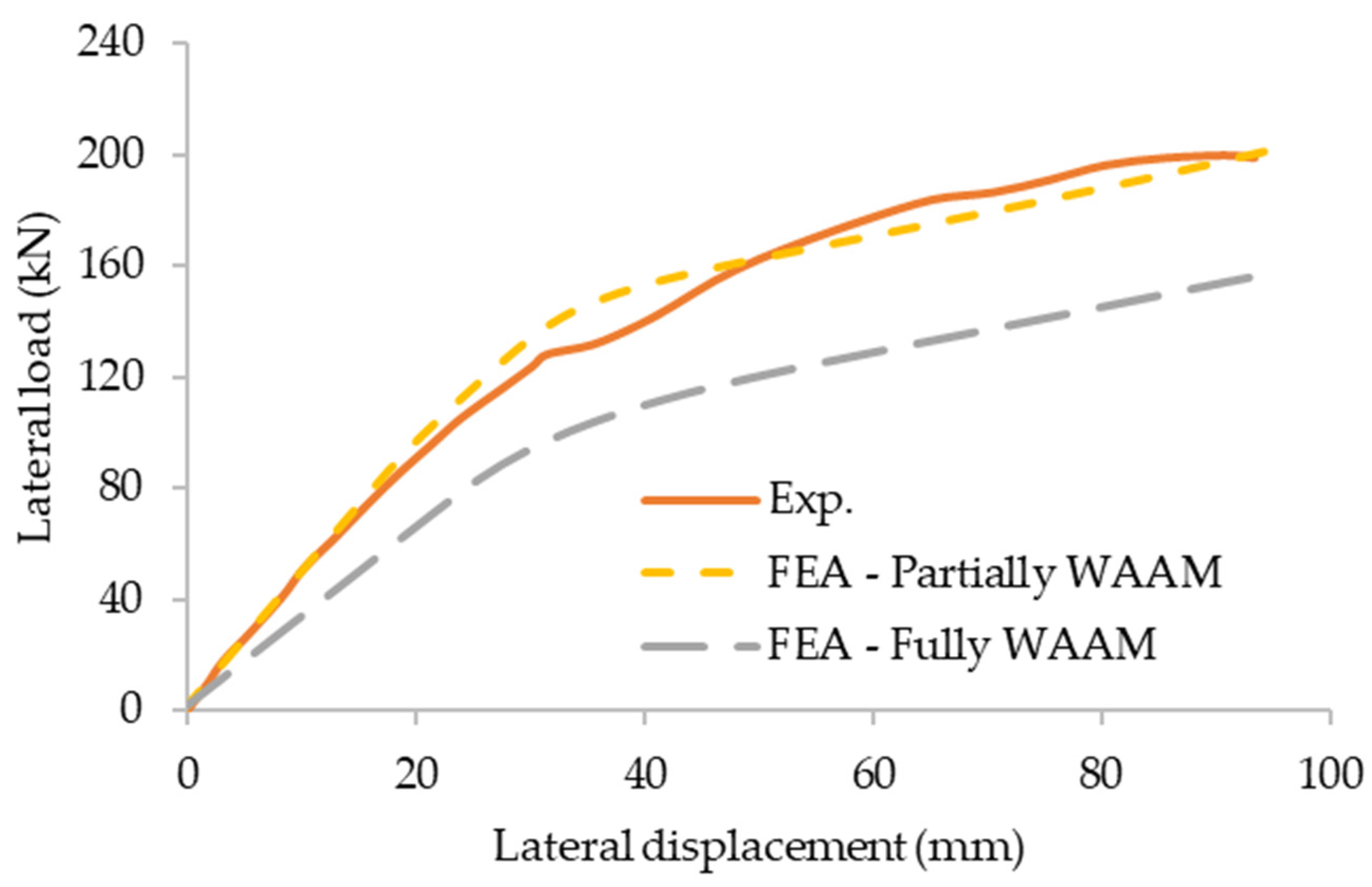
  • The effect of a 3D printed connection on structural response is negligible compared to the conventional modular steel connection when replacing selected 3D printed structural components that are not highly responsible for the behaviour of modular connections.
  • A significant reduction in the structural performance, such as load-bearing capacity and initial stiffness, was identified when the entire modular connection was 3D printed using the WAAM method.
  • In an attempt to calculate the equivalent WAAM thickness that offers similar structural performance to that of the traditional steel modular connections, the untreated thickness of the columns and beams in the connection was increased from 8 mm to 12 mm (50% increment of the thickness).
  • A 3D printed modular connection with θ = 45° print orientation showed identical structural behaviour compared to the reference modular connection, though the 3D printed modular connections with θ = 0° and θ = 90° print orientation resulted in relatively lower performance compared to the reference modular connection.
  • However, due to the practical limitations of producing the connections with θ = 45° print orientation, it is suggested to consider the material properties of treated WAAM products obtained in θ = 90° print orientation to examine the structural performance through numerical modelling.
Consequently, the numerical investigations carried out in this study provide insight into the structural response of 3DMBCs, which can be applied in making informed decisions when designing, preparing for 3D printing, and modelling modular building connections as well as other structural systems. The findings of this study support the wider use of WAAM-based connections in modular buildings and aim to provide confidence to engineers.

Author Contributions

Conceptualization, K.D.T. and K.P.; methodology, M.D. and T.S.; software, M.D.; validation, M.D.; formal analysis, M.D., T.S. and G.P.; investigation, M.D. and T.S.; data curation, M.D.; writing—original draft preparation, M.D., T.S. and G.P.; writing—review and editing, M.D., T.S., K.D.T. and K.P.; visualization, M.D.; supervision, K.D.T. and K.P.; project administration, K.D.T.; funding acquisition, K.D.T. All authors have read and agreed to the published version of the manuscript.

Funding

This research was funded by Leverhulme Trust grant number LTSRF1819\15\40.

Institutional Review Board Statement

Not applicable.

Informed Consent Statement

Not applicable.

Data Availability Statement

All the data supporting reported results can be found in the manuscript.

Acknowledgments

The authors would like to thank The Leverhulme Trust and Royal Academy of Engineering for their financial support to the project titled: “Flexible and Resilient 3D-Printed Metallic Connections for Modular Buildings” https://3dmbc.com, accessed on 24 November 2021.

Conflicts of Interest

The authors declare no conflict of interest.

References

  1. Peng, J.; Hou, C.; Shen, L. Lateral resistance of multi-story modular buildings using tenon-connected inter-module connections. J. Constr. Steel Res. 2021, 177, 106453. [Google Scholar] [CrossRef]
  2. Ye, Z.; Giriunas, K.; Sezen, H.; Wu, G.; Feng, D.-C. State-of-the-art review and investigation of structural stability in multi-story modular buildings. J. Build. Eng. 2021, 33, 101844. [Google Scholar] [CrossRef]
  3. Lacey, A.W.; Chen, W.; Hao, H.; Bi, K. Lateral behaviour of modular steel building with simplified models of new inter-module connections. Eng. Struct. 2021, 236, 112103. [Google Scholar] [CrossRef]
  4. Dai, Z.; Cheong, T.Y.C.; Pang, S.D.; Liew, J.Y.R. Experimental study of grouted sleeve connections under bending for steel modular buildings. Eng. Struct. 2021, 243, 112614. [Google Scholar] [CrossRef]
  5. Zhao, F.; Yu, Y.; Lin, S.; Ding, F. Evaluation of the working mechanisms and simplified models of endplate-type inter-module connections. Structures 2021, 32, 562–577. [Google Scholar] [CrossRef]
  6. Park, K.-S.; Moon, J.; Lee, S.-S.; Bae, K.-W.; Roeder, C.W. Embedded steel column-to-foundation connection for a modular structural system. Eng. Struct. 2016, 110, 244–257. [Google Scholar] [CrossRef]
  7. Lacey, A.W.; Chen, W.; Hao, H.; Bi, K. New interlocking inter-module connection for modular steel buildings: Simplified structural behaviours. Eng. Struct. 2021, 227, 111409. [Google Scholar] [CrossRef]
  8. Sendanayake, S.V.; Thambiratnam, D.P.; Perera, N.J.; Chan, T.H.T.; Aghdamy, S. Enhancing the lateral performance of modular buildings through innovative inter-modular connections. Structures 2021, 29, 167–184. [Google Scholar] [CrossRef]
  9. Allen, S.M.; Sachs, E.M. Three-dimensional printing of metal parts for tooling and other applications. Met. Mater. 2000, 6, 589–594. [Google Scholar] [CrossRef]
  10. Ashraf, M.; Gibson, I.; Rashed, M.G. Challenges and prospects of 3D printing in structural engineering. In Proceedings of the 13th International Conference on Steel, Space and Composite Structures, Perth, WA, Australia, 11 February 2018. [Google Scholar]
  11. Buchanan, C.; Matilainen, V.-P.; Salminen, A.; Gardner, L. Structural performance of additive manufactured metallic material and cross-sections. J. Constr. Steel Res. 2017, 136, 35–48. [Google Scholar] [CrossRef]
  12. Buchanan, C.; Gardner, L. Metal 3D printing in construction: A review of methods, research, applications, opportunities and challenges. Eng. Struct. 2019, 180, 332–348. [Google Scholar] [CrossRef]
  13. Galjaard, S.; Hofman, S.; Perry, N.; Ren, S. Optimizing structural building elements in metal by using additive manufacturing. In Proceedings of the IASS Annual Symposia, International Association for Shell and Spatial Structures (IASS), Amsterdam, The Netherlands, 2 August 2015; pp. 1–12. [Google Scholar]
  14. Pires, M.M. Finite Element Analysis of Residual Stresses in Metallic Parts Produced Byadditive Manufacturing. Master’s Thesis, University of Porto, Porto, Portugal, 2021. [Google Scholar]
  15. van Bolderen, G. Exploration of Stability of 3D-Printed Steel Members: A Study to Buckling Behaviour of Wire and Arc Additively Manufactured Stainless Steel Tubular Columns. Master’s Thesis, Delft University of Technology, Delft, The Netherlands, 2017. [Google Scholar]
  16. Laghi, V.; Palermo, M.; Gasparini, G.; Girelli, V.A.; Trombetti, T. Experimental results for structural design of Wire-and-Arc Additive Manufactured stainless steel members. J. Constr. Steel. Res. 2020, 167, 105858. [Google Scholar] [CrossRef]
  17. Gardner, L.; Kyvelou, P.; Herbert, G.; Buchanan, C. Testing and initial verification of the world’s first metal 3D printed bridge. J. Constr. Steel Res. 2020, 172, 106233. [Google Scholar] [CrossRef]
  18. Al-Nabulsi, Z.; Mottram, J.T.; Gillie, M.; Kourra, N.; Williams, M.A. Mechanical and X ray computed tomography characterisation of a WAAM 3D printed steel plate for structural engineering applications. Constr. Build. Mater. 2021, 274, 121700. [Google Scholar] [CrossRef]
  19. Kyvelou, P.; Slack, H.; Daskalaki Mountanou, D.; Wadee, M.A.; Britton, T.B.; Buchanan, C.; Gardner, L. Mechanical and microstructural testing of wire and arc additively manufactured sheet material. Mater. Des. 2020, 192, 108675. [Google Scholar] [CrossRef]
  20. Camacho, D.D.; Clayton, P.; O’Brien, W.J.; Jung, K.Y. 3D Printed Fastener-Free Connections for Non-Structural and Structural Applications–An Exploratory Investigation. In International Solid Freeform Fabrication Symposium; University of Texas: Austin, TX, USA, 2018. [Google Scholar]
  21. Lange, J.; Feucht, T.; Erven, M. 3D printing with steel. Steel Constr. 2020, 13, 144–153. [Google Scholar] [CrossRef]
  22. Lange, J.; Feucht, T. 3-D-Printing with Steel: Additive Manufacturing of Connection Elements and Beam Reinforcements. In Proceedings of the IABSE Symposium, Guimarães 2019: Towards a Resilient Built Environment Risk and Asset Management, Guimarães, Portugal, 27–29 March 2019; pp. 1836–1841. [Google Scholar]
  23. Khosravani, M.R.; Reinicke, T. Effects of raster layup and printing speed on strength of 3D-printed structural components. Procedia Struct. Integr. 2020, 28, 720–725. [Google Scholar] [CrossRef]
  24. Nurizada, A.; Kirane, K. Induced anisotropy in the fracturing behavior of 3D printed parts analyzed by the size effect method. Eng. Fract. Mech. 2020, 239, 107304. [Google Scholar] [CrossRef]
  25. Chen, Z.; Liu, J.; Yu, Y. Experimental study on interior connections in modular steel buildings. Eng. Struct. 2017, 147, 625–638. [Google Scholar] [CrossRef]
  26. Lockett, H.; Ding, J.; Williams, S.; Martina, F. Design for Wire+ Arc Additive Manufacture: Design rules and build orientation selection. J. Eng. Des. 2017, 28, 568–598. [Google Scholar] [CrossRef] [Green Version]
  27. Ding, J. Thermo-Mechanical Analysis of Wire and Arc Additive Manufacturing Process. Ph.D. Thesis, Cranfield University, Bedford, UK, 2012. [Google Scholar]
  28. Chen, Z.; Liu, J.; Yu, Y.; Zhou, C.; Yan, R. Experimental study of an innovative modular steel building connection. J. Constr. Steel Res. 2017, 139, 69–82. [Google Scholar] [CrossRef]
  29. Wang, M.; Shi, Y.; Wang, Y.; Shi, G. Numerical study on seismic behaviors of steel frame end-plate connections. J. Constr. Steel Res. 2013, 90, 140–152. [Google Scholar] [CrossRef]
  30. Krolo, P.; Grandić, D.; Bulić, M. The Guidelines for Modelling the Preloading Bolts in the Structural Connection Using Finite Element Methods. J. Comp. Eng. 2016, 2016, 4724312. [Google Scholar] [CrossRef] [Green Version]
  31. Khan, K.; Yan, J.-B. Finite Element Analysis on Seismic Behaviour of Novel Joint in Prefabricated Modular Steel Building. Int. J. Steel Struct. 2020, 20, 752–765. [Google Scholar] [CrossRef]
  32. Rasmussen, K.J. Full-range stress–strain curves for stainless steel alloys. J. Constr. Steel Res. 2003, 59, 47–61. [Google Scholar] [CrossRef]
  33. Arrayago, I.; Real, E.; Gardner, L. Description of stress–strain curves for stainless steel alloys. Mater. Des. 2015, 87, 540–552. [Google Scholar] [CrossRef]
Figure 1. Use of WAAM in steel connections [21]; (a) Double angle connection, (b) Equivalent beam hook, and (c) 3D printed beam hook using WAAM.
Buildings 12 00005 g001
Figure 2. Different mesh sizes employed.
Buildings 12 00005 g002
Figure 3. Test [28] and FE lateral load-deflection curves.
Buildings 12 00005 g003
Figure 4. Experimental [28] and FE failure modes.
Buildings 12 00005 g004
Figure 5. Experimental [17] and FE axial load-end shortening curves.
Buildings 12 00005 g005
Figure 6. Experimental [17] and FE failure modes.
Buildings 12 00005 g006
Figure 7. 3D printed components (illustrated in green colour) in WAAM modular connection [28].
Buildings 12 00005 g007
Figure 8. Lateral load-deflection behaviour of modular connection.
Buildings 12 00005 g008
Figure 9. Response of the partially WAAM 3DMBC to the lateral loading.
Buildings 12 00005 g009aBuildings 12 00005 g009b
Figure 10. Response of the fully WAAM 3DMBC to the lateral loading.
Buildings 12 00005 g010aBuildings 12 00005 g010b
Figure 11. Lateral load-displacement behaviour of modular connection with increased thickness.
Buildings 12 00005 g011
Figure 12. Lateral load-displacement behaviour of modular connection with treated WAAM surfaces.
Buildings 12 00005 g012
Table 1. Adopted stainless steel material properties in the study.
fy (MPa)fu (MPa)E (MPa)εu (%)nm
Typical SS308LSi407600200,00040.072.9
Untreated WAAM (θ = 90°) [17]271423109,10010.35.52.5
Treated WAAM (θ = 0°) [17]356575143,00030.715.82.4
Treated WAAM (θ = 45°) [17]407626219,50036.413.62.4
Treated WAAM (θ = 90°) [17]338554139,60029.76.82.7
Publisher’s Note: MDPI stays neutral with regard to jurisdictional claims in published maps and institutional affiliations.

