
Comparison of Different Procedures for Progressive Collapse Analysis of RC Flat Slab Structures under Corner Column Loss Scenario


Abstract
1. Introduction
2. Materials and Methods
2.1. Description of Reference Experiments
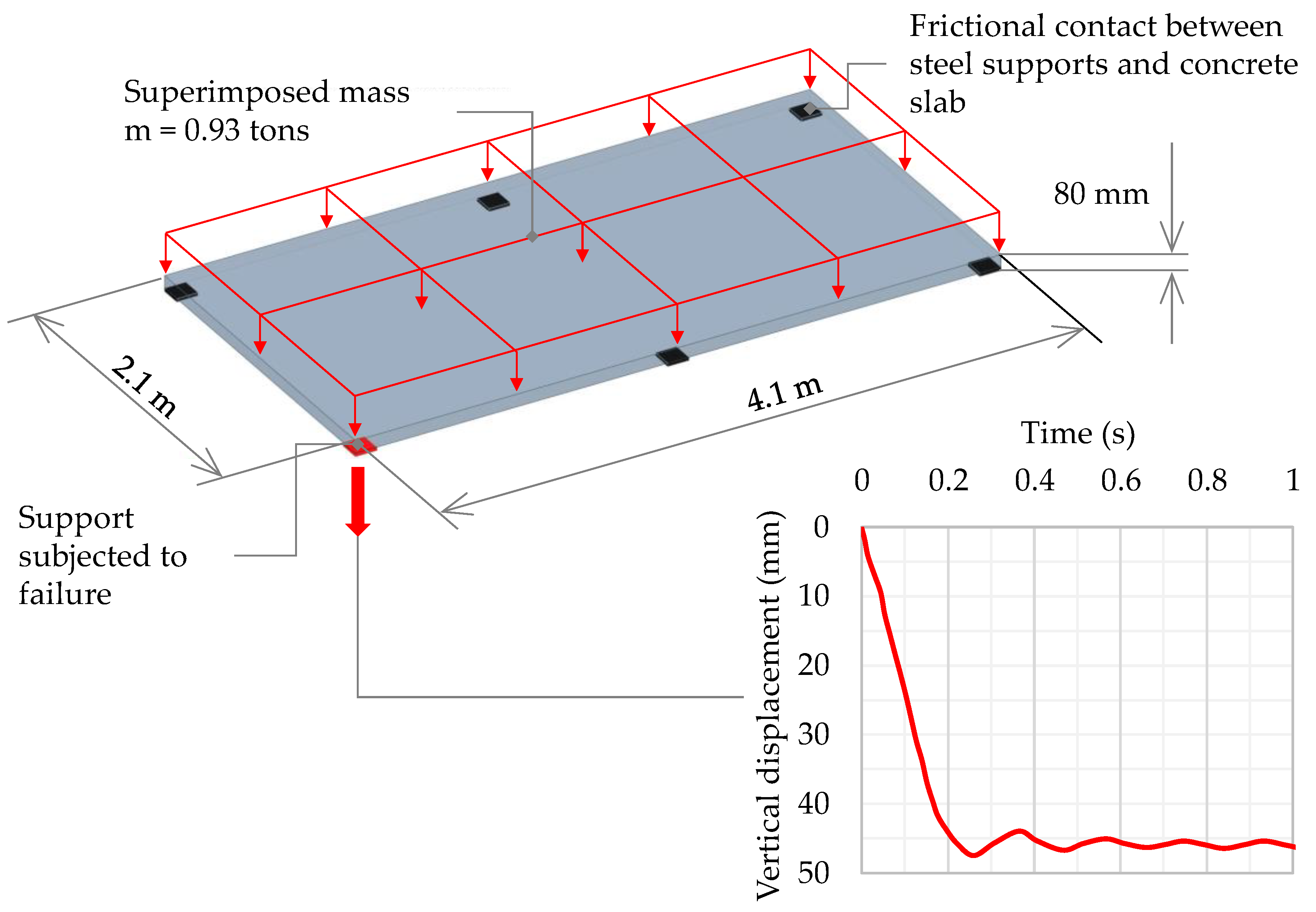
2.1.1. Corner Support Loss Scenario for Reinforced Concrete Flat Slab
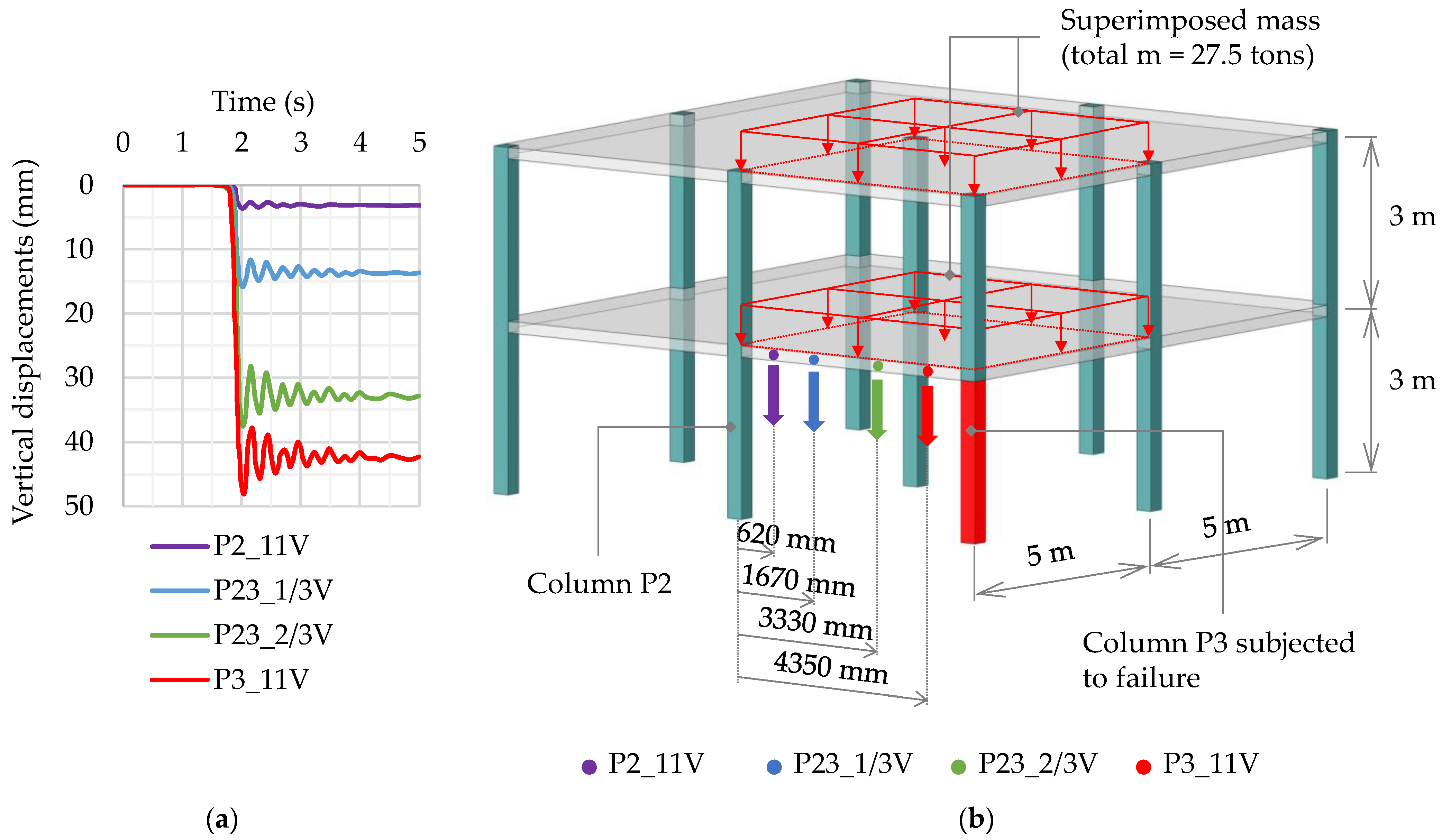
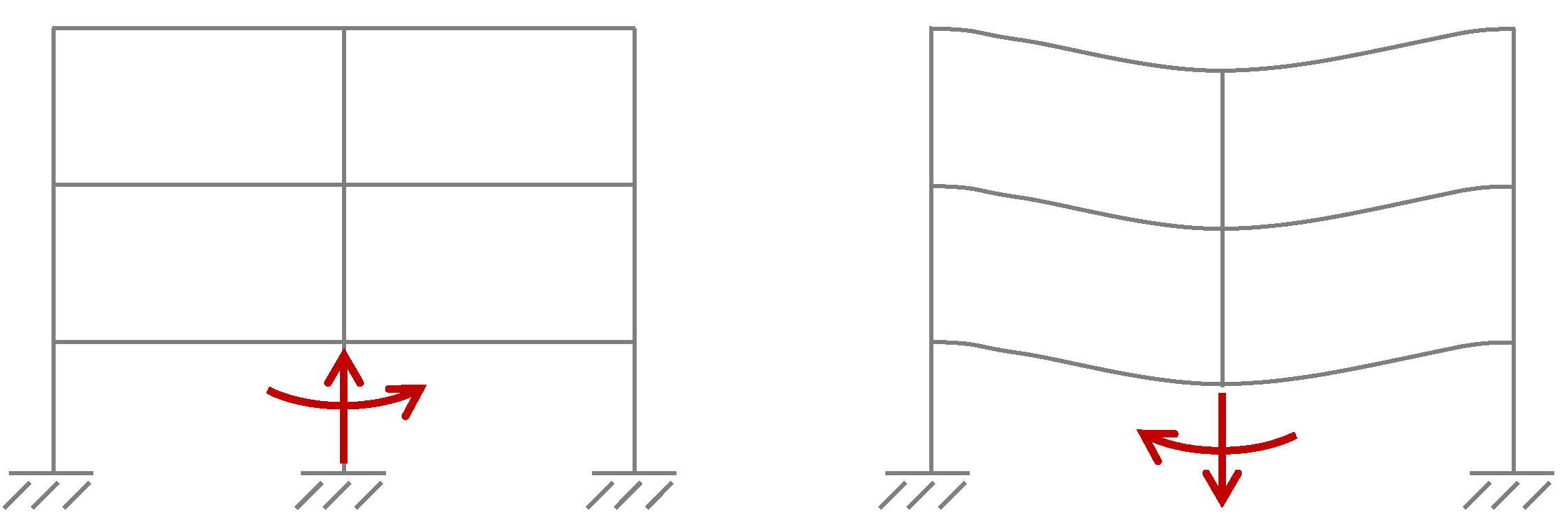
2.1.2. Corner Column Loss Scenario for Two-Story Reinforced Concrete Flat Slab Frame
2.2. Methodology for Simulation of Progressive Collapse
2.2.1. Governing Equations
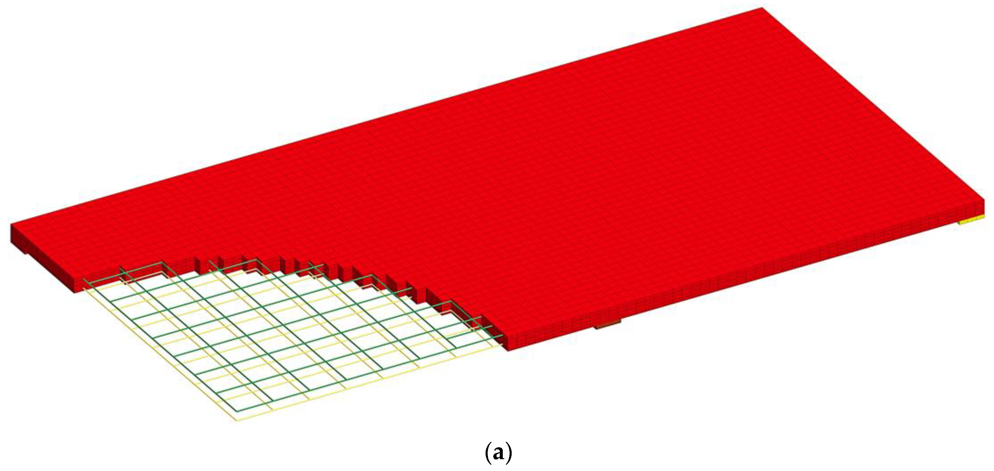
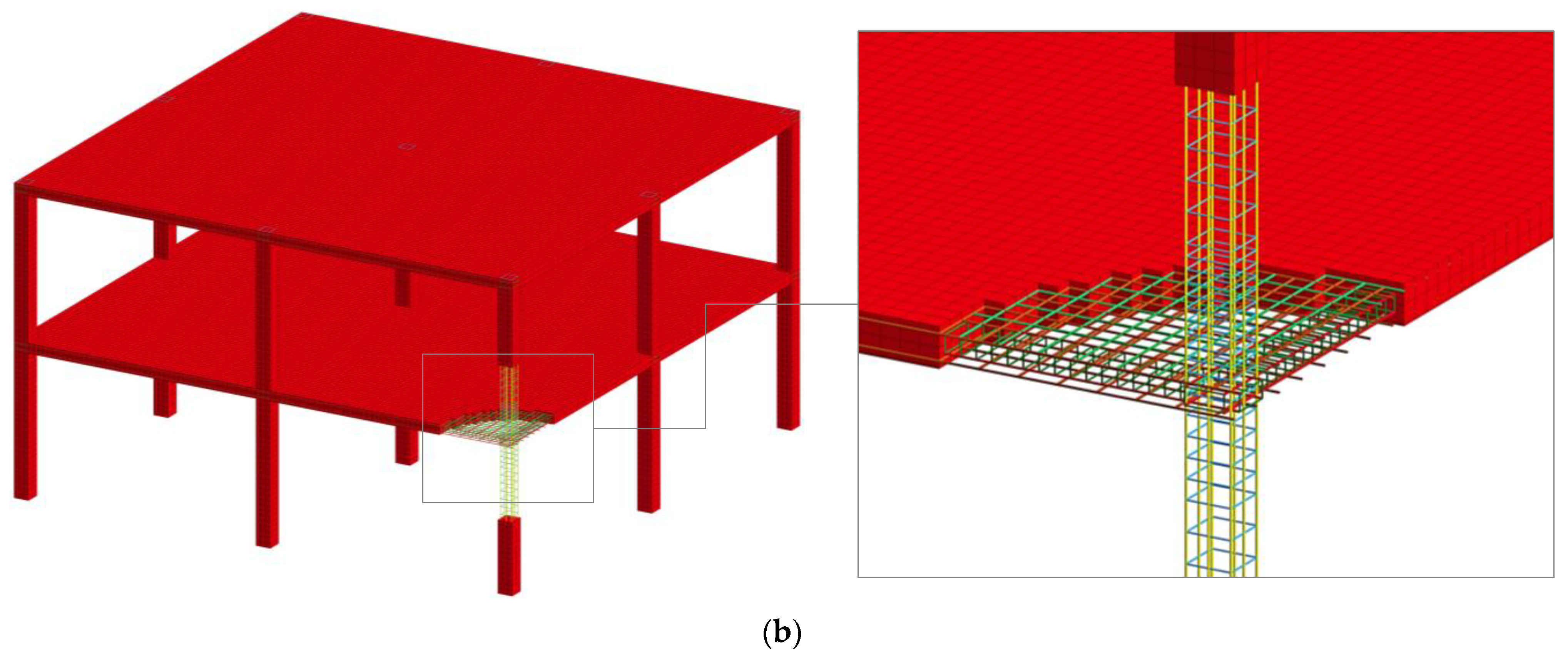
2.2.2. Finite Element Mesh
2.2.3. Material Models
2.3. Numerical Procedures for Progressive Collapse Analysis
3. Results
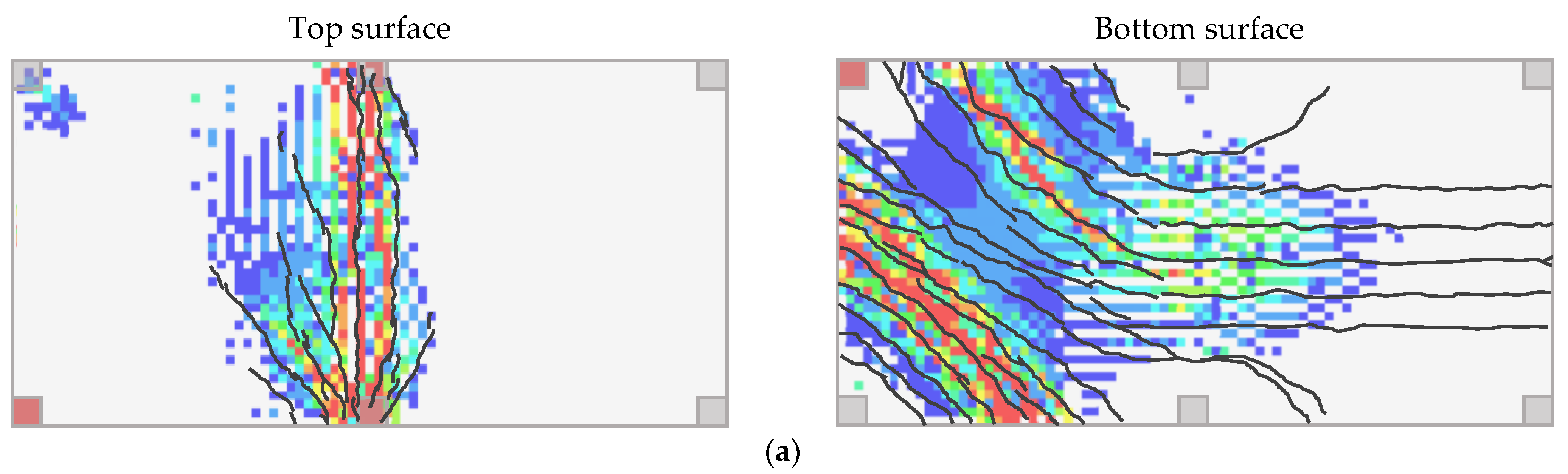
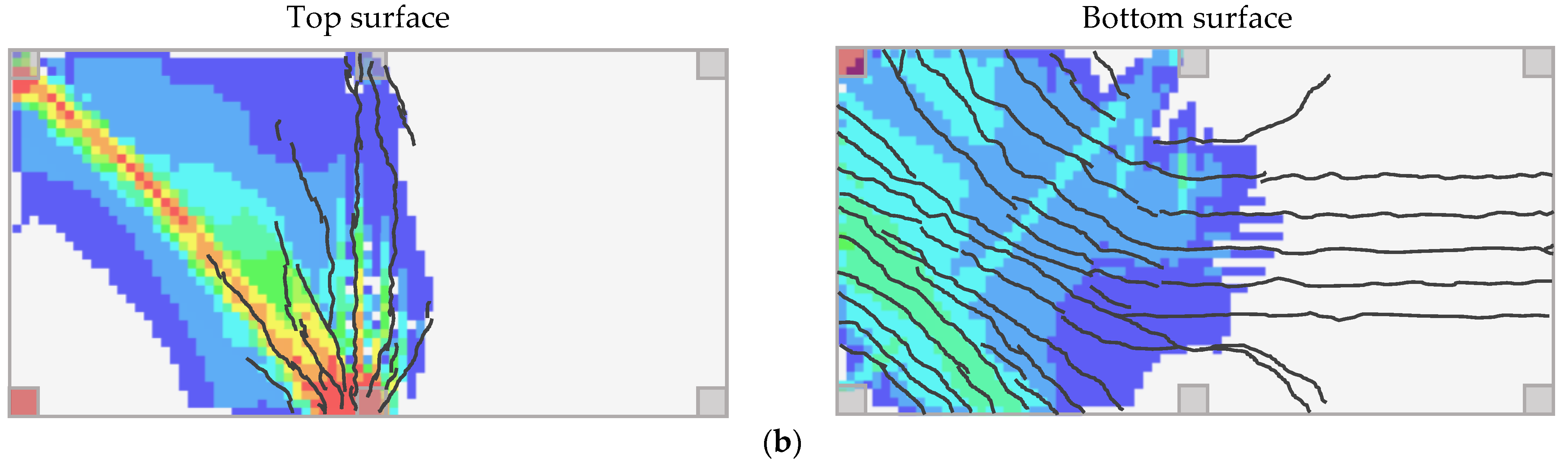
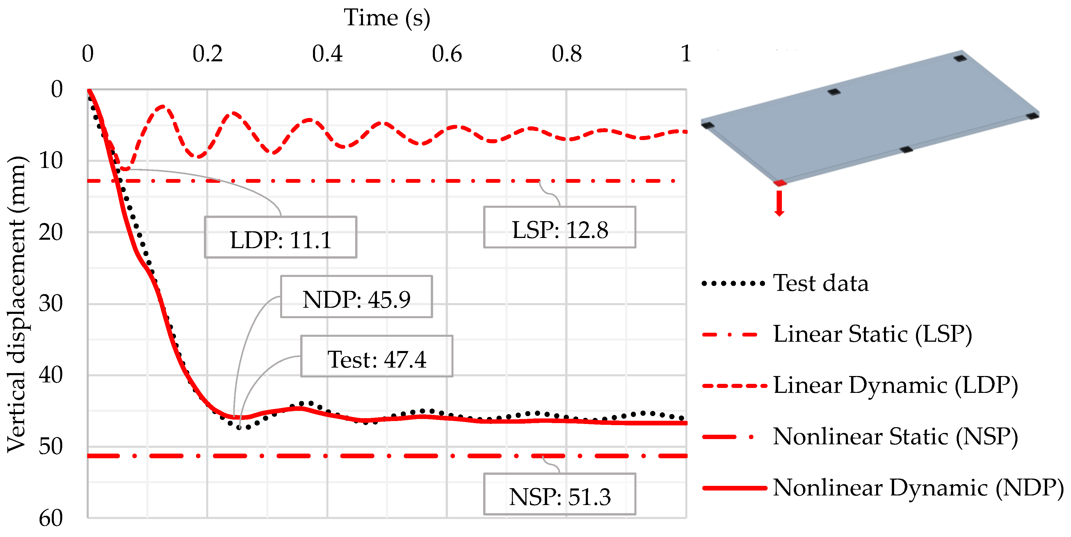
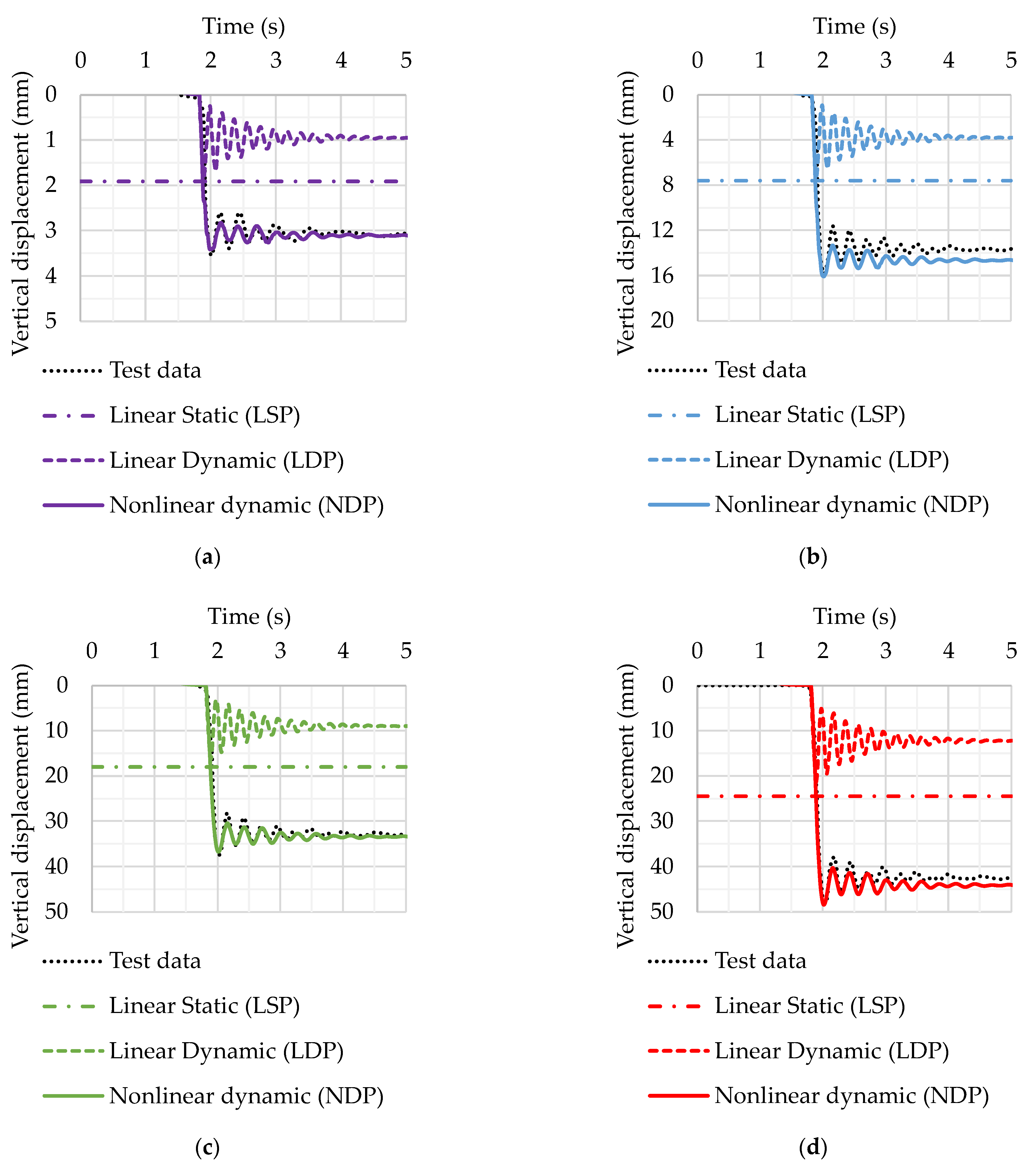
3.1. Corner Support Loss Scenario for Reinforced Concrete Flat Slab
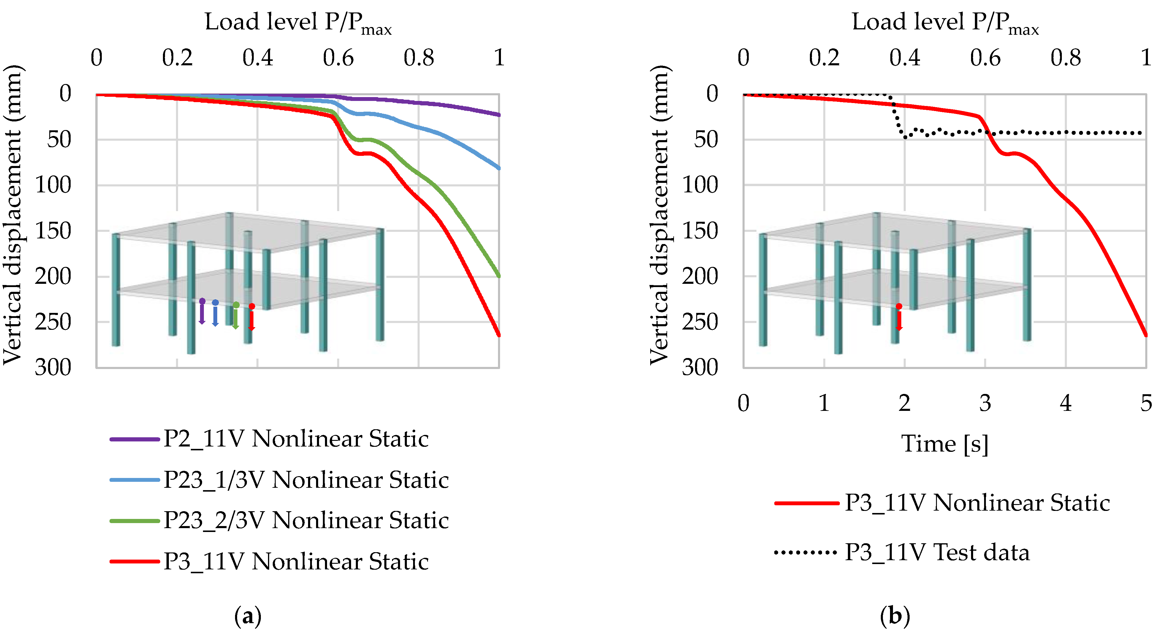
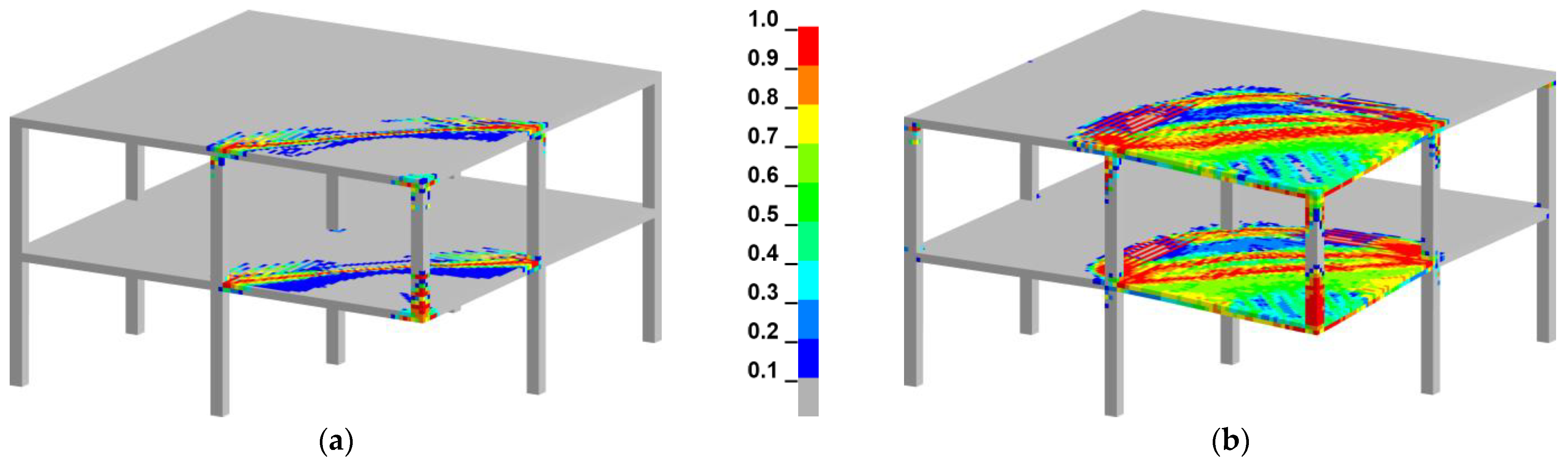
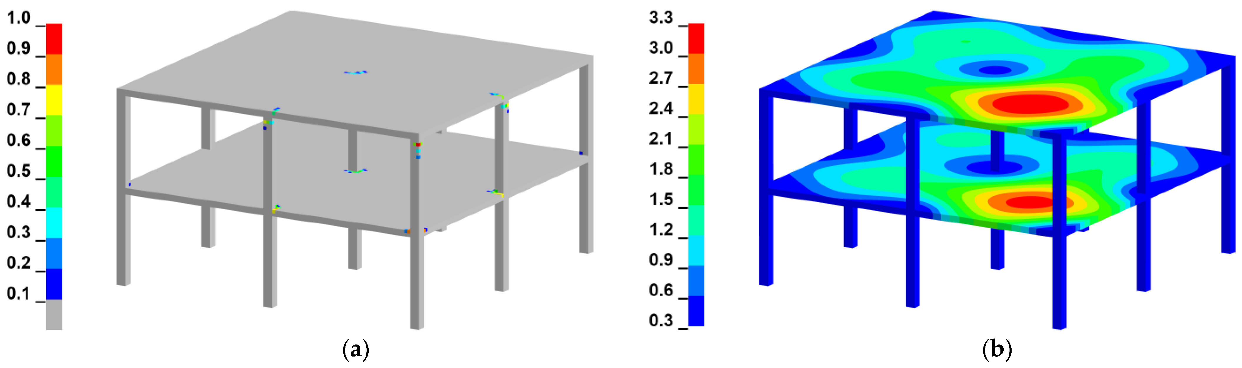
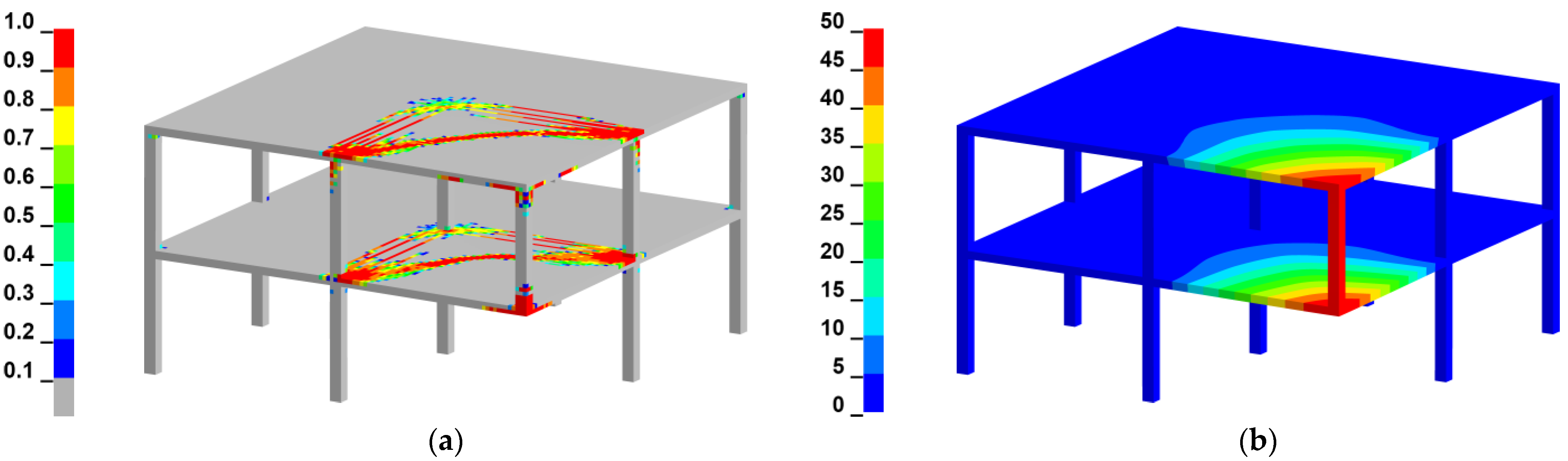
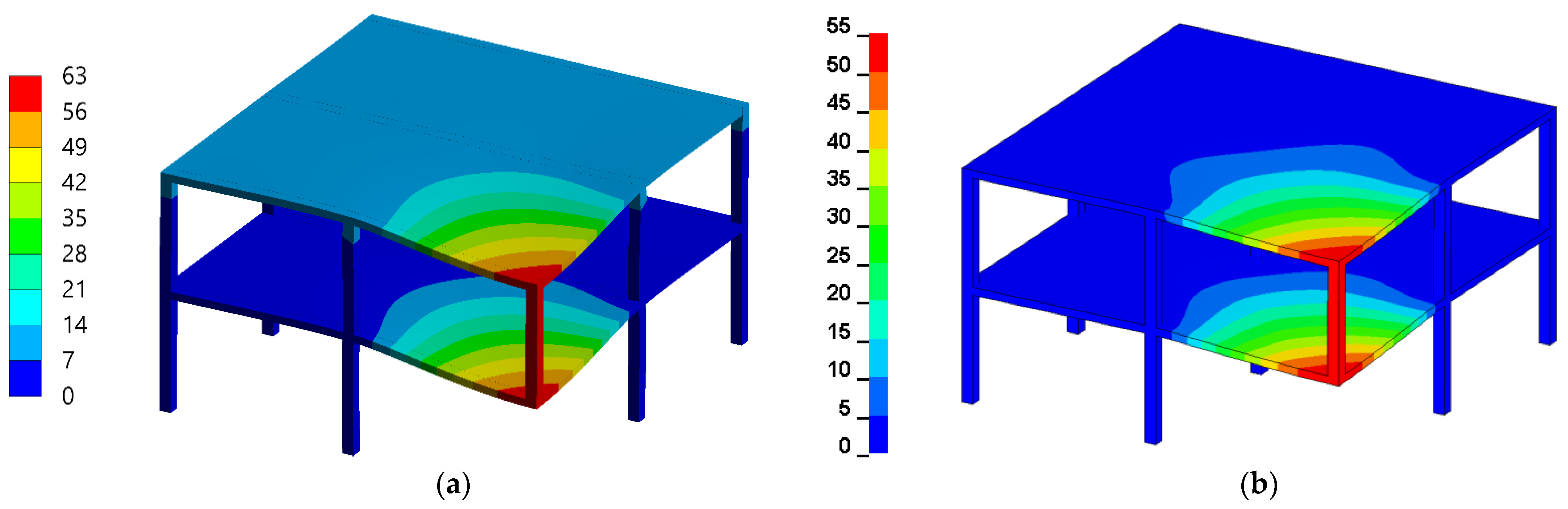
3.2. Corner Column Loss Scenario for a Two-Story Reinforced Concrete Frame
4. Discussion
Author Contributions
Funding
Institutional Review Board Statement
Informed Consent Statement
Acknowledgments
Conflicts of Interest
References
- Ellingwood, B.R.; Smilowitz, R.; Dusenberry, D.O.; Duthinh, D.; Lew, H.S.; Carino, N.J. Best Practices for Reducing the Potential for Progressive Collapse in Buildings; Gaithersburg; National Institute of Standards and Technology: Gaithersburg, MD, USA, 2007.
- Kokot, S.; Solomos, G. Progressive Collapse Risk Analysis: Literature Survey, Relevant Construction Standards and Guidelines; Joint Research Centre: Brussels, Belgium; European Commission: Luxembourg, 2012. [Google Scholar]
- Cuoco, D.A.; Peraza, D.B.; Scarangello, T.Z. Investigation of L’Ambiance Plaza Building Collapse. J. Perform. Constr. Facil. 1992, 6, 211–231. [Google Scholar] [CrossRef]
- Heger, F.J. Public-Safety Issues in Collapse of L’Ambiance Plaza. J. Perform. Constr. Facil. 1991, 5, 92–112. [Google Scholar] [CrossRef]
- Martin, R.; Delatte, N.J. Another Look at the L’Ambiance Plaza Collapse. J. Perform. Constr. Facil. 2000, 14, 160–165. [Google Scholar] [CrossRef]
- Mohamed, O.A. Progressive Collapse of Structures: Annotated Bibliography and Comparison of Codes and Standards. J. Perform. Constr. Facil. 2006, 20, 418–425. [Google Scholar] [CrossRef]
- Bazant, Z.P.; Le, J.-L.; Greening, F.R.; Benson, D.B. What Did and Did Not Cause Collapse of World Trade Center Twin Towers in New York? J. Eng. Mech. 2008, 134, 892–906. [Google Scholar] [CrossRef]
- Bažant, Z.P.; Verdure, M. Mechanics of Progressive Collapse: Learning from World Trade Center and Building Demolitions. J. Eng. Mech. 2007, 133, 308–319. [Google Scholar] [CrossRef]
- Wang, H.; Zhang, A.; Li, Y.; Yan, W. A Review on Progressive Collapse of Building Structures. Open Civ. Eng. J. 2014, 8, 183–192. [Google Scholar] [CrossRef]
- Qian, K.; Hu, H.-N.; Fu, F.; Deng, X.-F. Dynamic Behavior of Precast Concrete Beam-Column Sub-Assemblages with High Performance Connections Subjected to Sudden Column Removal Scenario. In Proceedings of the Structures Congress 2020, St. Louis, MO, USA, 5–8 April 2020; American Society of Civil Engineers: Reston, VA, USA, 2020; pp. 467–474. [Google Scholar]
- Kai, Q.; Li, B. Dynamic performance of RC beam-column substructures under the scenario of the loss of a corner column—Experimental results. Eng. Struct. 2012, 42, 154–167. [Google Scholar] [CrossRef]
- Russell, J.M. Progressive Collapse of Reinforced Concrete Flat Slab Structures. Ph.D. Thesis, University of Nottingham, Nottingham, UK, 2015. [Google Scholar]
- Russell, J.; Owen, J.; Hajirasouliha, I. Experimental investigation on the dynamic response of RC flat slabs after a sudden column loss. Eng. Struct. 2015, 99, 28–41. [Google Scholar] [CrossRef]
- Peng, Z.; Orton, S.L.; Liu, J.; Tian, Y. Experimental Study of Dynamic Progressive Collapse in Flat-Plate Buildings Subjected to Exterior Column Removal. J. Struct. Eng. 2017, 143, 04017125. [Google Scholar] [CrossRef]
- Peng, Z.; Orton, S.L.; Liu, J.; Tian, Y. Experimental Study of Dynamic Progressive Collapse in Flat-Plate Buildings Subjected to an Interior Column Removal. J. Struct. Eng. 2018, 144, 04018094. [Google Scholar] [CrossRef]
- Xiao, Y.; Zhao, Y.B.; Li, F.W.; Kunnath, S.; Lew, H.S. Collapse Test of a 3-Story Half-Scale RC Frame Structure. In Proceedings of the Structures Congress 2013, Pittsburgh, PA, USA, 2–4 May 2013; American Society of Civil Engineers: Reston, VA, USA, 2013; pp. 11–19. [Google Scholar]
- Adam, J.M.; Buitrago, M.; Bertolesi, E.; Sagaseta, J.; Moragues, J.J. Dynamic performance of a real-scale reinforced concrete building test under a corner-column failure scenario. Eng. Struct. 2020, 210, 110414. [Google Scholar] [CrossRef]
- Wang, T.; Zhang, L.; Zhao, H.; Chen, Q. Progressive collapse resistance of reinforced-concrete frames with specially shaped columns under loss of a corner column. Mag. Concr. Res. 2016, 68, 1–15. [Google Scholar] [CrossRef]
- Zhang, L.; Zhao, H.; Wang, T.; Chen, Q. Parametric Analysis on Collapse-resistance Performance of Reinforced-concrete Frame with Specially Shaped Columns Under Loss of a Corner Column. Open Constr. Build. Technol. J. 2016, 10, 466–480. [Google Scholar] [CrossRef]
- Ren, P.; Li, Y.; Zhou, Y.; Lu, X.; Guan, H. Experimental Study on the Progressive Collapse Resistance of RC Slabs. In Proceedings of the Structures Congress 2014, Boston, MA, USA, 3–5 May 2014; American Society of Civil Engineers: Boston, MA, USA, 2014; pp. 1–12. [Google Scholar]
- Lu, X.; Lin, K.; Li, Y.; Guan, H.; Ren, P.; Zhou, Y. Experimental investigation of RC beam-slab substructures against progressive collapse subject to an edge-column-removal scenario. Eng. Struct. 2017, 149, 91–103. [Google Scholar] [CrossRef]
- Darweesh, K.I.A. Experimental and Theoretical Evaluation of Progressive Collapse Capacity of Reinforced Concrete Framed Structures. Ph.D. Thesis, University of Salford, Salford, UK, 2017. [Google Scholar]
- Elsanadedy, H.M.; Al-Salloum, Y.A.; Almusallam, T.H.; Ngo, T.; Abbas, H. Assessment of progressive collapse potential of special moment resisting RC frames—Experimental and FE study. Eng. Fail. Anal. 2019, 105, 896–918. [Google Scholar] [CrossRef]
- Lim, N.S.; Tan, K.; Lee, C. Experimental studies of 3D RC substructures under exterior and corner column removal scenarios. Eng. Struct. 2017, 150, 409–427. [Google Scholar] [CrossRef]
- Yu, J.; Rinder, T.; Stolz, A.; Tan, K.-H.; Riedel, W. Dynamic Progressive Collapse of an RC Assemblage Induced by Contact Detonation. J. Struct. Eng. 2014, 140, 04014014. [Google Scholar] [CrossRef]
- Qian, K.; Li, B. Dynamic and residual behavior of reinforced concrete floors following instantaneous removal of a column. Eng. Struct. 2017, 148, 175–184. [Google Scholar] [CrossRef]
- Bermejo, M.; Santos, A.P.; Goicolea, J.M. Development of Practical Finite Element Models for Collapse of Reinforced Concrete Structures and Experimental Validation. Shock. Vib. 2017, 2017, 1–9. [Google Scholar] [CrossRef]
- Qian, K.; Weng, Y.-H.; Li, B. Impact of two columns missing on dynamic response of RC flat slab structures. Eng. Struct. 2018, 177, 598–615. [Google Scholar] [CrossRef]
- Liu, J.; Tian, Y.; Orton, S.L.; Said, A.M. Resistance of Flat-Plate Buildings against Progressive Collapse. I: Modeling of Slab-Column Connections. J. Struct. Eng. 2015, 141, 04015053. [Google Scholar] [CrossRef]
- Liu, J.; Tian, Y.; Orton, S.L. Resistance of Flat-Plate Buildings against Progressive Collapse. II: System Response. J. Struct. Eng. 2015, 141, 04015054. [Google Scholar] [CrossRef]
- Keyvani, L.; Sasani, M.; Mirzaei, Y. Compressive membrane action in progressive collapse resistance of RC flat plates. Eng. Struct. 2014, 59, 554–564. [Google Scholar] [CrossRef]
- Kwasniewski, L. Nonlinear dynamic simulations of progressive collapse for a multistory building. Eng. Struct. 2010, 32, 1223–1235. [Google Scholar] [CrossRef]
- Pham, A.T.; Tan, K.H.; Yu, J. Numerical investigations on static and dynamic responses of reinforced concrete sub-assemblages under progressive collapse. Eng. Struct. 2017, 149, 2–20. [Google Scholar] [CrossRef]
- Parisi, F.; Scalvenzi, M.; Brunesi, E. Performance limit states for progressive collapse analysis of reinforced concrete framed buildings. Struct. Concr. 2018, 20, 68–84. [Google Scholar] [CrossRef]
- Brunesi, E.; Nascimbene, R.; Parisi, F. Progressive Collapse Fragility Models of RC Framed Buildings Based on Pushdown Analysis. In Proceedings of the VII European Congress on Computational Methods in Applied Sciences and Engineering (ECCOMAS Congress 2016), Crete, Greece, 5–10 June 2016; Institute of Structural Analysis and Antiseismic Research School of Civil Engineering National Technical University of Athens (NTUA): Athens, Greece, 2016; Volume 3, pp. 4900–4919. [Google Scholar]
- Brunesi, E.; Parisi, F. Progressive collapse fragility models of European reinforced concrete framed buildings based on pushdown analysis. Eng. Struct. 2017, 152, 579–596. [Google Scholar] [CrossRef]
- Goudarzi, H.R.V. Nonlinear Dynamic Analysis of Reinforced Concrete Frames under Extreme Loadings. Ph.D. Thesis, The University of New South Wales, Sydney, Australia, 2009. [Google Scholar]
- Marjanishvili, S.; Agnew, E. Comparison of Various Procedures for Progressive Collapse Analysis. J. Perform. Constr. Facil. 2006, 20, 365–374. [Google Scholar] [CrossRef]
- Fialko, S.Y.; Kabantsev, O.V.; Perelmuter, A.V. Elasto-Plastic Progressive Collapse Analysis Based on the Integration of the Equations of Motion. Mag. Civ. Eng. 2021, 102, 1–10. [Google Scholar] [CrossRef]
- Ministry of Construction Industry, Housing and Utilities Sector. SP 385.1325800.2018 Protection of Buildings and Structures against Progressive Collapse. Design Code. Basic Statements; Standartinform: Moscow, Russia, 2019.
- Department of Defense. Unified Facilities Criteria: Design of Buildings to Resist Progressive Collapse UFC 4-023-03; Department of Defense: Washington, DC, USA, 2016.
- United States General Services Administration. Alternate Path Analysis and Design Guidelines for Progressive Collapse Resistance; General Services Administration: Washington, DC, USA, 2013.
- Jiang, B.; Li, G.-Q.; Li, L.; Izzuddin, B.A. Experimental Studies on Progressive Collapse Resistance of Steel Moment Frames under Localized Furnace Loading. J. Struct. Eng. 2018, 144, 04017190. [Google Scholar] [CrossRef]
- Kang, H.; Kim, J. Progressive Collapse of Steel Moment Frames Subjected to Vehicle Impact. J. Perform. Constr. Facil. 2015, 29, 04014172. [Google Scholar] [CrossRef]
- Adam, J.M.; Parisi, F.; Sagaseta, J.; Lu, X. Research and practice on progressive collapse and robustness of building structures in the 21st century. Eng. Struct. 2018, 173, 122–149. [Google Scholar] [CrossRef]
- Guchinsky, R. The Onset of a Progressive Collapse During the Deconstruction of the Sports Building. Constr. Unique Build. Struct. 2021, 96, 1–15. [Google Scholar] [CrossRef]
- Formisano, A.; Iazzetta, G.; Marino, G.; Fabbrocino, F.; Landolfo, R. Seismic Residual Capacity Assessment of Framed Structures Damaged by Exceptional Actions. In Proceedings of the VII European Congress on Computational Methods in Applied Sciences and Engineering (ECCOMAS Congress 2016), Crete, Greece, 5–10 June 2016; Institute of Structural Analysis and Antiseismic Research School of Civil Engineering National Technical University of Athens (NTUA): Athens, Greece, 2016; Volume 3, pp. 4942–4958. [Google Scholar]
- Ratnika, L.; Gaile, L.; Vatin, N. Impact of Groundwater Level Change on Natural Frequencies of RC Buildings. Buildings 2021, 11, 265. [Google Scholar] [CrossRef]
- Szyniszewski, S. Effects of Random Imperfections on Progressive Collapse Propagation. In Proceedings of the Structures Congress 2010, Orlando, FL, USA, 12–15 May 2010; American Society of Civil Engineers: Reston, VA, USA, 2010; pp. 3572–3577. [Google Scholar]
- Ferraioli, M.; Lavino, A.; Mandara, A.; Donciglio, M.; Formisano, A. Seismic and Robustness Design of Steel Frame Buildings. Key Eng. Mater. 2018, 763, 116–123. [Google Scholar] [CrossRef]
- Birbraer, A.N.; Roleder, A.J. Extreme Actions on Structures; Publishing House of the Polytechnical University: St. Petersburg, Russia, 2009; ISBN 978-5-7422-2370-2. [Google Scholar]
- Murray, Y.; Abu-Odeh, A.; Bligh, R. Evaluation of LS-DYNA Concrete Material Model 159; United States, Federal Highway Administration, Office of Research, Development, and Technology: McLean, VA, USA, 2007. [Google Scholar]
- Murray, Y. Users Manual for LS-DYNA Concrete Material Model 159; United States, Federal Highway Administration, Office of Research, Development, and Technology: McLean, VA, USA, 2007. [Google Scholar]
- Markou, G. Computational Performance of an Embedded Reinforcement Mesh Generation Method for Large-Scale RC Simulations. Int. J. Comput. Methods 2015, 12, 1550019. [Google Scholar] [CrossRef]
- Barzegar, F.; Maddipudi, S. Generating Reinforcement in FE Modeling of Concrete Structures. J. Struct. Eng. 1994, 120, 1656–1662. [Google Scholar] [CrossRef]
- Hallquist, J. LS-DYNA Theory Manual; Livermore Software Technology Corporation: Livermore, CA, USA, 2007; ISBN 9254492507. [Google Scholar]
- ANSYS. Mechanical APDL Theory Reference; ANSYS Inc.: Canonsburg, PA, USA, 2016. [Google Scholar]
- Lalin, V.V.; Dmitriev, A.N.; Diakov, S.F. Nonlinear deformation and stability of geometrically exact elastic arches. Mag. Civ. Eng. 2019, 89, 39–51. [Google Scholar] [CrossRef]
- Fung, Y.C.; Tong, P.; Chen, X. Classical and Computational Solid Mechanics: Advanced Series in Engineering Science; World Scientific Publishing Company: Singapore, 2017; ISBN 978-981-4713-64-1. [Google Scholar]
- Dmitriev, A.; Novozhilov, Y.; Mikhalyuk, D.; Lalin, V. Calibration and Validation of the Menetrey-Willam Constitutive Model for Concrete. Stroitel’stvo Unikal’nyh Zdanij i Sooruzenij 2020, 8, 8804. [Google Scholar] [CrossRef]
- Dmitriev, A.; Lalin, V.; Novozhilov, Y.; Mikhalyuk, D. Simulation of Concrete Plate Perforation by Coupled Finite Element and Smooth Particle Hydrodynamics Methods. Constr. Unique Build. Struct. 2020, 92, 9207. [Google Scholar] [CrossRef]
- Novozhilov, Y.V.; Dmitriev, A.N.; Mikhaluk, D.S.; Chernukha, N.A.; Feoktistova, L.Y.; Volkodav, I.A. Aircraft NPP Impact Simulation Methodology. In Proceedings of the 16th International LS-DYNA® Users Conference, Barcelona, Spain, 10 June 2020; pp. 1–14. [Google Scholar]
- Dmitriev, A.; Lalin, V.; Melnikov, A. Validation of Computational Procedures for the Progressive Collapse Analysis of Reinforced Concrete Structures. In Proceedings of the EECE 2020, St. Petersburg, Russia, 19–20 November 2020; Springer: Berlin/Heidelberg, Germany, 2021; pp. 215–224. [Google Scholar] [CrossRef]
- Wei, J.; Li, J.; Wu, C. An experimental and numerical study of reinforced conventional concrete and ultra-high performance concrete columns under lateral impact loads. Eng. Struct. 2019, 201, 109822. [Google Scholar] [CrossRef]
- Weng, Y.-H.; Qian, K.; Fu, F.; Fang, Q. Numerical investigation on load redistribution capacity of flat slab substructures to resist progressive collapse. J. Build. Eng. 2019, 29, 101109. [Google Scholar] [CrossRef]
- Levi-Hevroni, D.; Kochavi, E.; Kofman, B.; Gruntman, S.; Sadot, O. Experimental and numerical investigation on the dynamic increase factor of tensile strength in concrete. Int. J. Impact Eng. 2018, 114, 93–104. [Google Scholar] [CrossRef]
- Jiang, H.; Zhao, J. Calibration of the continuous surface cap model for concrete. Finite Elements Anal. Des. 2015, 97, 1–19. [Google Scholar] [CrossRef]
- International Atomic Energy Agency. Safety Aspects of Nuclear Power Plants in Human Induced External Events: Assessment of Structures; International Atomic Energy Agency: Vienna, Austria, 2018. [Google Scholar]
- Liu, M. Pulldown Analysis for Progressive Collapse Assessment. J. Perform. Constr. Facil. 2015, 29, 04014027. [Google Scholar] [CrossRef]
- Formisano, A.; Landolfo, R.; Mazzolani, F. Robustness assessment approaches for steel framed structures under catastrophic events. Comput. Struct. 2015, 147, 216–228. [Google Scholar] [CrossRef]
- Kokot, S.; Anthoine, A.; Negro, P.; Solomos, G. Static and dynamic analysis of a reinforced concrete flat slab frame building for progressive collapse. Eng. Struct. 2012, 40, 205–217. [Google Scholar] [CrossRef]
- Tsai, M.-H. An analytical methodology for the dynamic amplification factor in progressive collapse evaluation of building structures. Mech. Res. Commun. 2010, 37, 61–66. [Google Scholar] [CrossRef]
- McKay, A.; Marchand, K.; Diaz, M. Alternate Path Method in Progressive Collapse Analysis: Variation of Dynamic and Nonlinear Load Increase Factors. Pr. Period. Struct. Des. Constr. 2012, 17, 152–160. [Google Scholar] [CrossRef]
- Marchand, K.; McKay, A.; Stevens, D.J. Development and Application of Linear and Non-Linear Static Approaches in UFC 4-023-03. In Proceedings of the Structures Congress 2009: Don’t Mess with Structural Engineers: Expanding Our Role, Austin, TX, USA, 30 April–2 May 2009; pp. 1–10. [Google Scholar] [CrossRef]
- Bathe, K.-J. Finite Element Procedures; Prentice Hall: Hoboken, NJ, USA, 1996. [Google Scholar]
- Bathe, K.-J.; Noh, G. Insight into an implicit time integration scheme for structural dynamics. Comput. Struct. 2012, 98–99, 1–6. [Google Scholar] [CrossRef]
- Belytschko, T.; Liu, W.K.; Moran, B.; Elkhodary, K. Nonlinear finite elements for continua and structures. Choice Rev. Online 2001, 38, 38–3926. [Google Scholar] [CrossRef]


| Method | Maximum Vertical Displacement | Residual Vertical Displacement | ||
|---|---|---|---|---|
| Value (mm) | Mismatch (%) | Value (mm) | Mismatch (%) | |
| Test data | 47.4 | N/A | 46.0 | N/A |
| Linear Static | 12.8 | 73.0 | 12.8 | 72.2 |
| Linear Dynamic | 11.1 | 76.6 | 5.9 | 87.2 |
| Nonlinear Static | 51.3 | 8.2 | 51.3 | 11.5 |
| Nonlinear Dynamic | 45.9 | 3.2 | 46.7 | 1.5 |
| Method | Maximum Vertical Displacement | Residual Vertical Displacement | ||
|---|---|---|---|---|
| Value (mm) | Mismatch (%) | Value (mm) | Mismatch (%) | |
| Linear Static | 24.5 | 49.1 | 24.5 | 42.8 |
| Linear Dynamic | 21.4 | 55.5 | 12.3 | 71.3 |
| Nonlinear Static | 264.5 | 449.9 | 264.5 | 518.0 |
| Nonlinear Dynamic | 48.4 | 0.6 | 44.1 | 3.0 |
Publisher’s Note: MDPI stays neutral with regard to jurisdictional claims in published maps and institutional affiliations. |
© 2021 by the authors. Licensee MDPI, Basel, Switzerland. This article is an open access article distributed under the terms and conditions of the Creative Commons Attribution (CC BY) license (https://creativecommons.org/licenses/by/4.0/).
Share and Cite
Dmitriev, A.N.; Lalin, V.V. Comparison of Different Procedures for Progressive Collapse Analysis of RC Flat Slab Structures under Corner Column Loss Scenario. Buildings 2021, 11, 405. https://doi.org/10.3390/buildings11090405
Dmitriev AN, Lalin VV. Comparison of Different Procedures for Progressive Collapse Analysis of RC Flat Slab Structures under Corner Column Loss Scenario. Buildings. 2021; 11(9):405. https://doi.org/10.3390/buildings11090405
Chicago/Turabian StyleDmitriev, Andrey Nikolaevich, and Vladimir Vladimirovich Lalin. 2021. "Comparison of Different Procedures for Progressive Collapse Analysis of RC Flat Slab Structures under Corner Column Loss Scenario" Buildings 11, no. 9: 405. https://doi.org/10.3390/buildings11090405
APA StyleDmitriev, A. N., & Lalin, V. V. (2021). Comparison of Different Procedures for Progressive Collapse Analysis of RC Flat Slab Structures under Corner Column Loss Scenario. Buildings, 11(9), 405. https://doi.org/10.3390/buildings11090405