Article

Intervention Strategies for the Seismic Improvement of Masonry Buildings Based on FME Validation: The Case of a Terraced Building Struck by the 2016 Central Italy Earthquake

Department of Cultural Heritage, University of Padova, Piazza Capitaniato 7, 35139 Padova, Italy
*
Author to whom correspondence should be addressed.
Buildings 2021, 11(9), 404; https://doi.org/10.3390/buildings11090404
Submission received: 27 July 2021 / Revised: 2 September 2021 / Accepted: 6 September 2021 / Published: 10 September 2021
(This article belongs to the Section Building Structures)

Abstract

:
Residential masonry buildings represent a large stock among highly vulnerable structures in medium–high seismic hazard areas, often built without any anti-seismic provisions. Their rehabilitation and/or strengthening according to optimised intervention strategies is topical and may contribute to revaluating zones characterized by depopulation phenomena. In this paper, a terraced building struck by the 2016 Central Italy earthquake is analysed through a frame by macro element (FME) model. The building is composed of six two-storey units made of stone and clay block masonry walls and semi-rigid diaphragms. The numerical model was calibrated based on the damage pattern caused by the earthquake and then used to carry out parametric analyses on the strengthened conditions by simulating both one unit and the entire terrace. The effects of interventions applied to either vertical or horizontal components, both singularly and in combination, were analysed in terms of nonlinear static analyses, and quantified by a performance factor, according to the upgraded seismic code in Italy. Kinematic analyses also completed the assessment of the building. Results compared the capacity of interventions in attaining the targets defined for improvement at both local and overall levels.

1. Introduction

1.1. Seismic Risk of Residential Buildings

Existing buildings may present several vulnerabilities, which reduce their performance against seismic actions, mainly owing to: (i) unavailability or incompleteness of codes at the time of construction; (ii) shortcomings in material choice; (iii) defects in design and construction details; (iv) effect of time in functioning (e.g., conservation state, maintenance works). According to [1], only 20% of buildings in the EU were constructed after modern seismic rules had been passed (around the 1990s) and about 40% of them are over 60 years old. Therefore, in seismic areas, the retrofit of such buildings is urgent; besides economic losses, severe injuries and high casualties occur owing to earthquakes of moderate intensity [2].
Residential buildings account for 75% of the total stock in Europe, of which 64% consists of single-family houses, i.e., detached, semi-detached, or terraced houses (the rest being apartment blocks) [1,3]. In Italy, 87% of residential buildings correspond to masonry and reinforced concrete (r.c.) constructions; of these, more than 90% (masonry) and 55% (r.c.) were constructed without seismic-resistant detailing (the reason being that the reference building codes for anti-seismic design of structures passed in Italy in the early 1980s) [4]. Italy also has a high seismic risk (in terms of both hazard of the sites, and vulnerability and exposure of the buildings) [5]: 45% of the entire building stock is located in moderate-to-high seismic hazard areas (seismicity classes 1–2 out of 4) [6,7]. Single houses account for 72% of the whole built stock [1], among which terraced buildings are widespread, particularly in historical settlements located in hilly or mountainous contexts [8].
Terraced buildings develop as a sequence of identical or very similar units, usually two- or three-storeys high, stretching along the streets. The internal units of the row share their adjacent transverse walls, whereas openings (i.e., doors and windows) are present in the front and back facades, as well as at the extreme wall caps. Therefore, terraced houses are particularly vulnerable to earthquakes in their extreme units, where out-of-plane collapses can prevail, especially in the case of flexible (e.g., timber) [9] or semi-rigid (e.g., precast r.c. or steel joists with clay block or tile subflooring) [8] diaphragms. A proper evaluation of the seismic performance of this type of buildings is a staple for their rehabilitation and the identification of optimised strengthening solutions. In-depth studies carried out in the late 1990s on historical centres of central Italy (Umbria and Marche regions) struck by earthquakes brought to light the concept of ‘building aggregates’ composed of closely interacting units [10,11]. Further research in the aftermath of the L’Aquila earthquake (in the Abruzzi region) [12] confirmed the role of the interaction and connections between adjacent units, and proposed a middle-term assessment method for the seismic vulnerability analyses of a building aggregate. The Frame by Macro Element (FME) method was applied to carry out nonlinear static (pushover) analyses and define fragility curves for the significant damage limit states. The influence of input parameters in a model’s definition, such as the mechanical and geometrical properties of the structure, and their consistency with the actual building conditions were found to be fundamental for the accuracy of outcomes. In [13], an aggregate located in the same region was studied by comparing FME and finite element method (FEM) models with a novel kinematic approach based on non-uniform rational B-spline (NURBS) surfaces to carry out adaptive limit analyses. This study underlined the need for integrating overall analyses with the assessment of local mechanism for buildings lacking the ‘box-like’ behaviour, and it provided the safety coefficients related to the modelling approaches. Recent studies [14] in a nearby area (the Lazio region) investigated two facing large aggregates: the influence in the performance of the perimeter walls lacking the bracing effect at the extreme buildings, as well as of openings, was pointed out by an FEM model. The limits in the representativeness of the model in terms of interlocking between walls, type of masonry, lateral constraints, and distribution of vertical and horizontal loads among the components were also discussed in that work. However, a wider analysis on the contribution of the materials and the elements which compose a structural system is required [15], especially with respect to the high variability found in existing masonry buildings.
In this paper, the FME method was applied to a two-storey terraced house composed of six units, using 3Muri software [16]. The building dates back to the mid-1960s and it is made of low-quality masonry walls, semi-rigid diaphragms, and poor detailing. It was damaged during the 2016 Central Italy earthquake, which caused a widespread shear damage on the piers and a few local out-of-plane (OOP) collapses. Nonlinear static (pushover) analyses permitted the calibration of the numerical model on the basis of the observed crack pattern, and to simulate three intervention strategies. The analyses varied in terms of bearing walls’ mechanical parameters (strength and Young’s modulus), connecting devices, and diaphragms’ in-plane (IP) stiffness. The improvement achieved by interventions in terms of seismic capacity was evaluated for both a single unit and the whole terrace, according to the current building code, to identify the most suitable techniques.

1.2. Strenghening of Masonry Buildings

Strengthening strategies on existing unreinforced masonry (URM) buildings in seismic areas concern various interventions, aimed at improving the capacity of either single components (i.e., walls, floors, and roof) or the whole structure, to achieve a unitary behaviour of the structural system and control the global deformation, especially versus the horizontal loads. However, in the case of existing URM buildings, the integration of new materials (e.g., concrete) and elements (e.g., reinforcing layers on vertical and horizontal components, ring, or tie beams) must be carefully considered in terms of their actual effects, that is, beneficial or detrimental. The post-earthquake observations carried out in Italy over the last 25 years clarified this issue: the contribution of interventions on a building’s behaviour can be ‘unfavourable’ when OOP mechanisms and masonry crumbling phenomena are not prevented, and ‘favourable’ when the box-like behaviour is reached (i.e., floor inertial loads are redistributed among shear walls) [17]. The effectiveness of interventions also depends on their workmanship and compatibility with a building’s original features [18]. In fact, the negative contribution of strengthening is mainly caused by replacing the original timber joists in horizontal diaphragms with heavier r.c. precast elements or cast-in-place ribbed r.c. slabs, but without a suitable improvement of the masonry walls [19,20].
The Italian seismic code [21,22] has recently updated the general classification of interventions for existing buildings in: (a) repair or local interventions (on single structural elements); (b) improving interventions; and (c) upgrading interventions. This envisages a progressive approach, aimed at pursuing the maximum reduction in the average seismic risk at national scale given the limited resources available, by the means of frequent, low-impact, and widespread interventions.
Assuming a performance-based approach, the code relates each category (a)–(c) to the normalized parameter ζE. It expresses the ratio between the peak ground acceleration (PGA) that causes a structure to achieve a certain limit state (i.e., capacity PGA), generally severe damage [23], and the input value of PGA as defined by [21] for the specific site where a building is located. Therefore, ζE is defined as ‘performance ratio’, as it describes a generic building’s seismic performance in comparison with a reference ‘new’ one (i.e., designed according to modern criteria, ζE = 1). As the performance ratio can be evaluated at any limit state of structural interest (i.e., damage limitation, severe damage, near collapse), it is the key parameter in the current framework of seismic risk reduction policies in Italy [24] through the estimate of the expected average annual loss due to seismic damage [25]. In such a framework:
(a)
Repair interventions aim to prevent local collapse mechanisms, restore and/or improve the capacity of damaged or undamaged portions, leaving ζE unchanged. These actions, although circumscribed to single macroblocks (e.g., walls or portions of them delimited by discontinuities), are a staple in URM buildings, which especially suffer from brittle OOP failure and, secondarily, from weak IP response [26].
(b)
Improvement interventions aim to increase the safety level of an existing structure, without reaching those levels required for new constructions: ζE must be increased by 0.1 for ordinary buildings, but it should reach at least 0.6 in buildings for public use (e.g., schools) or which serve strategic functions (e.g., town halls).
(c)
Upgrading refers to those interventions which are able to make the structure achieve the safety level of a new one (ζE = 1) (e.g., extensions or substantial structural changes); however, a target of ζE = 0.8 is allowed in the cases of functional and usage changes.
Clearly, (a) and (b) include less impacting actions than (c), and are preferentially addressed to existing buildings to better comply with conservation criteria (e.g., minimum intervention, compatibility, and, when possible, reversibility and respect of authenticity) [27,28].
A building’s performance levels, as well as the corresponding values of ζE, can be estimated according to different scales (single macroblock or wall, whole structure), approaches (mainly kinematic or nonlinear static analyses), and conditions (as-built or designed ones). However, in both improvement and upgrading cases, an overall model is the preferred option.
Figure 1 shows an incremental procedure which guides the choice of intervention types as a function of the vulnerabilities commonly recognized in URM buildings and in the framework of those seismic performance targets (i.e., the ‘objectives’) required by the seismic code. Mode 0 stands for crumbling of inadequate-quality masonry (no macroblocks can be identified); mode 1 refers to OOP failure of macroblocks (no box-like behaviour can be identified). Mode 2 involves the IP resistance of walls: for the best performance, shear damage should occur preferably in spandrels than piers (i.e., keeping the bearing walls extended for the whole height of the structure as undamaged as possible) [29,30,31]. As modes 0 and 1 describe negative conditions (i.e., those which imply the potential loss of a building), the chart proposes specific countermeasures to contrast their activation (objectives 0 and 1, respectively); conversely, mode 2 is the preferred structural behaviour; therefore, the interventions are applied when it is not reached (e.g., interventions on diaphragms, objective 2). It is worth noting that the strengthening of walls is proposed only following mode 2 interventions (objective 3), when minimum performance levels are not met, in spite of the box-like behaviour. The progressive application of interventions minimizes the risk of their potential unfavourable contribution, as each stage is propaedeutic to the following one. Moreover, the impact of interventions can be adjusted depending on the final level of expected seismic performance, i.e., either improvement (lighter interventions) or upgrading (massive and/or widespread interventions).
This approach can be easily applied to case studies as a preliminary guideline to identify the most suitable intervention techniques in the framework of the current regulations. A pilot application on a real building is described in the following.

2. Materials and Methods

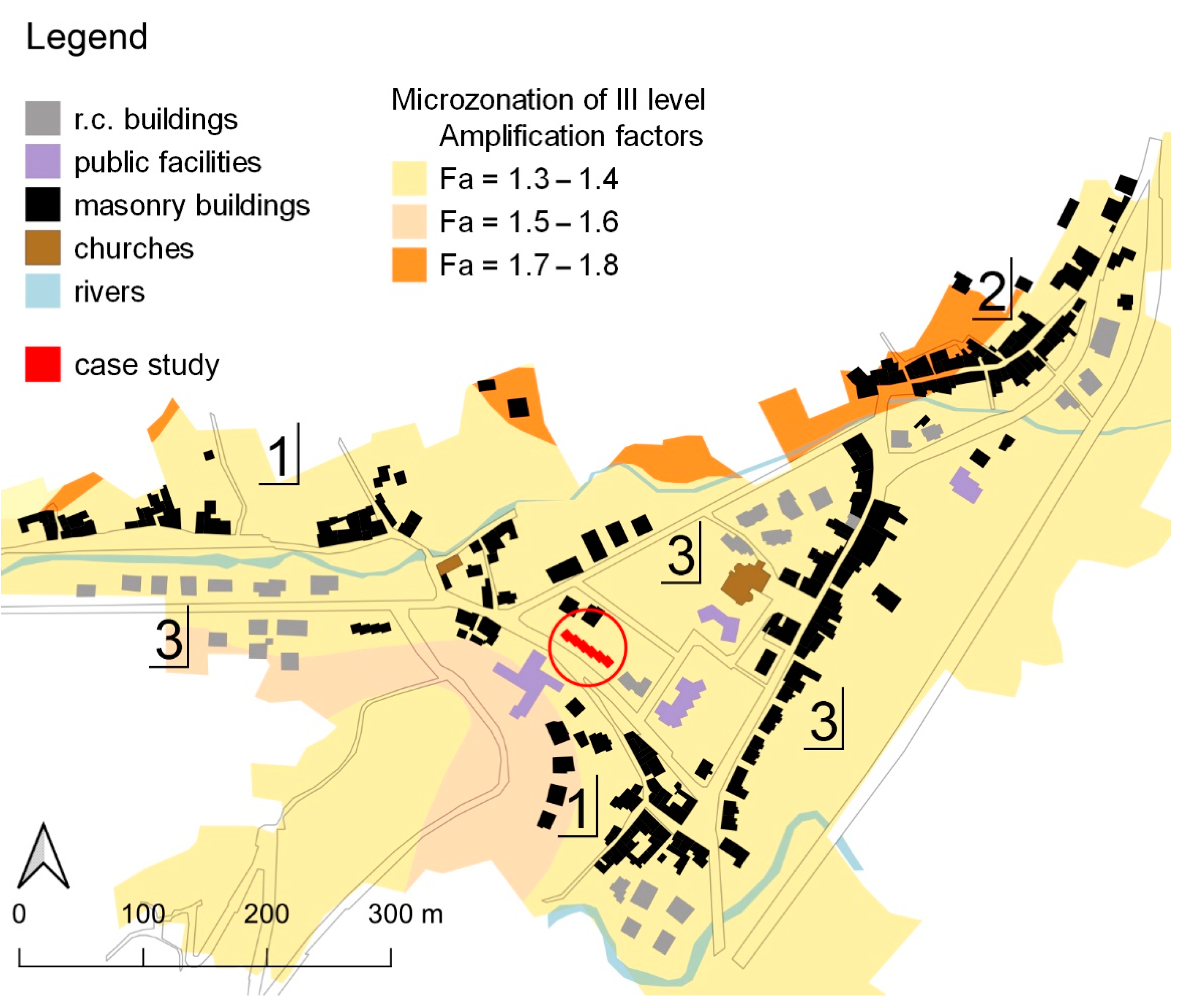
2.1. Urban and Seismic Context

The case study is located in Pieve Torina, a village in the Marche region, Central Italy. Pieve Torina has pre-Roman origins and stands at 470 m above sea level on a foothill area at the left side of the Chienti Valley. In the 18th century, new agglomerates of terraced houses and masonry building aggregates around the medieval nucleus were built [32]. During the 20th century, Pieve Torina was supplied with public facilities (middle school, town hall) and housing promoted by the IACP (Italian acronym for Local Public Housing Authority), which connected the old building nuclei. The case study presented herein is part of this last expansion of the village (Figure 2).
Frequent earthquakes in the area—Pieve Torina is classified in the highest hazard (zone 1, according to the Italian seismic zonation [6])—resulted in progressive depopulation; according to the most recent census data (2019), the village counts about 1300 inhabitants. Therefore, the rehabilitation of damaged buildings and/or their strengthening aimed at mitigating the current vulnerabilities is topical in this area.
The 2016 Central Italy earthquake (first shock on 24 August, moment magnitude Mw 6.0, followed by those of 26 and 30 October, Mw 5.4 and up to 6.5, respectively) provoked relevant damage. Pieve Torina was 24.2 km away from the epicentre of the 30 October event; according to the European Macroseismic Scale 1998 (EMS-98) [33], the village suffered a local intensity level of VIII, which was the highest registered in its history [34].
Marl is the main lithology of the settlement; moreover, alluvial deposits supplied building materials in terms of stones (limestone, sandstone), binder, and aggregates for mortar [35]. The third-level seismic microzonation defines the amplification factors for such types of subsoil: for structural periods ranging from 0.10 to 0.50 s (i.e., those typical of ordinary masonry buildings [36]), the whole area where the village stands refers to a factor of 1.40. This is consistent with a class C subsoil according to [21]. The PGA expected at the damage limitation (DL) and severe damage (SD) limit states are, respectively, 0.09 g and 0.223 g [37].
Figure 2 shows the urban plan of Pieve Torina and its microzonation analysis.

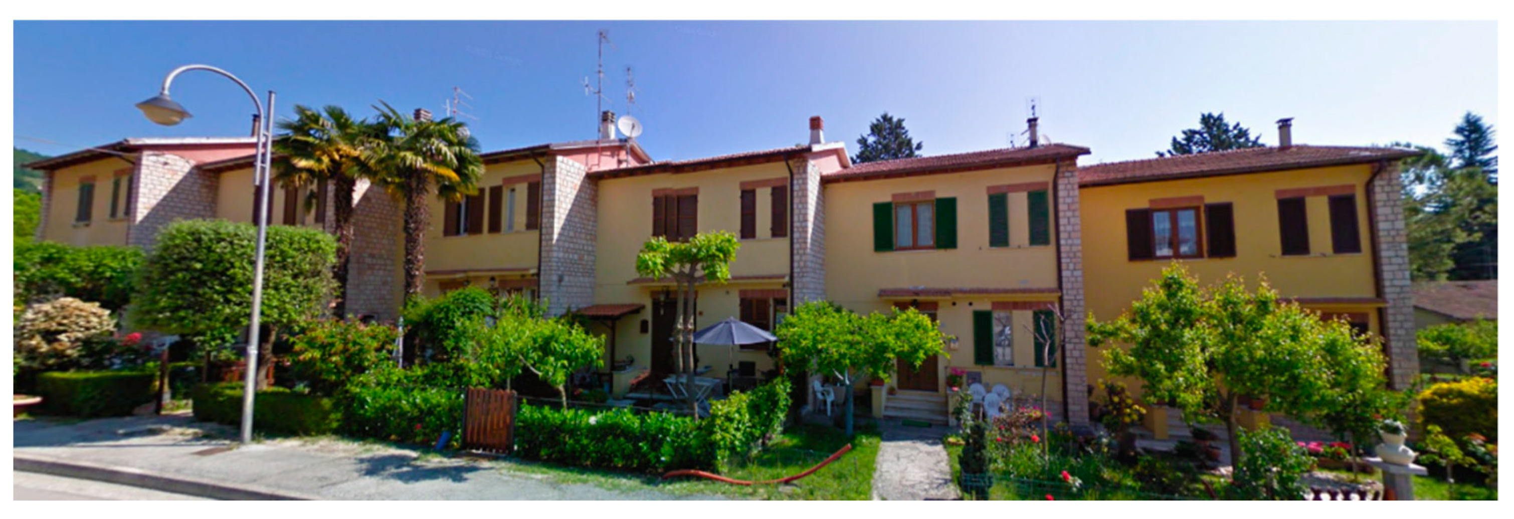
2.2. Case Study Description

The case study, henceforth referred to as IACP building, is a terraced building built in the mid-1960s, i.e., earlier than any seismic regulation applied to Pieve Torina [38]. It is composed of six units stretching along the NW–SE axis for a length of 43.17 m and a depth of 6.85 m towards north. Each unit has a compact and regular shape (plan of 7.57 × 6.85 m) with vertically aligned openings on the south and north facades only (Figure 3). The building has two storeys (gross area of 50 m2 per level and unit) and a basement, emerging for 0.70 m from the ground level, for a total elevation of 6.90 m in the north and the south facades from the ground to the eave line. Units are shifted for about 1.5 m. The gable walls on the east and west sides are completely blind; the ridge stands at 9.07 m above the ground. The walkable area of each floor is 34 m2, while the staircase has a footprint of about 4 m2. A loadbearing wall divides the raised ground floor, whilst, in the upper storey, there are only non-structural partitions; a non-structural ceiling also completes the first storey. The gross volume above ground is about 2094 m3.
In this study, the dwelling units are identified by a progressive number from east to west, as shown in Figure 4, which also reports the geometrical characteristics of IACP building. The X and Y reference axes correspond to the longitudinal and transverse directions of the terraced building, respectively.

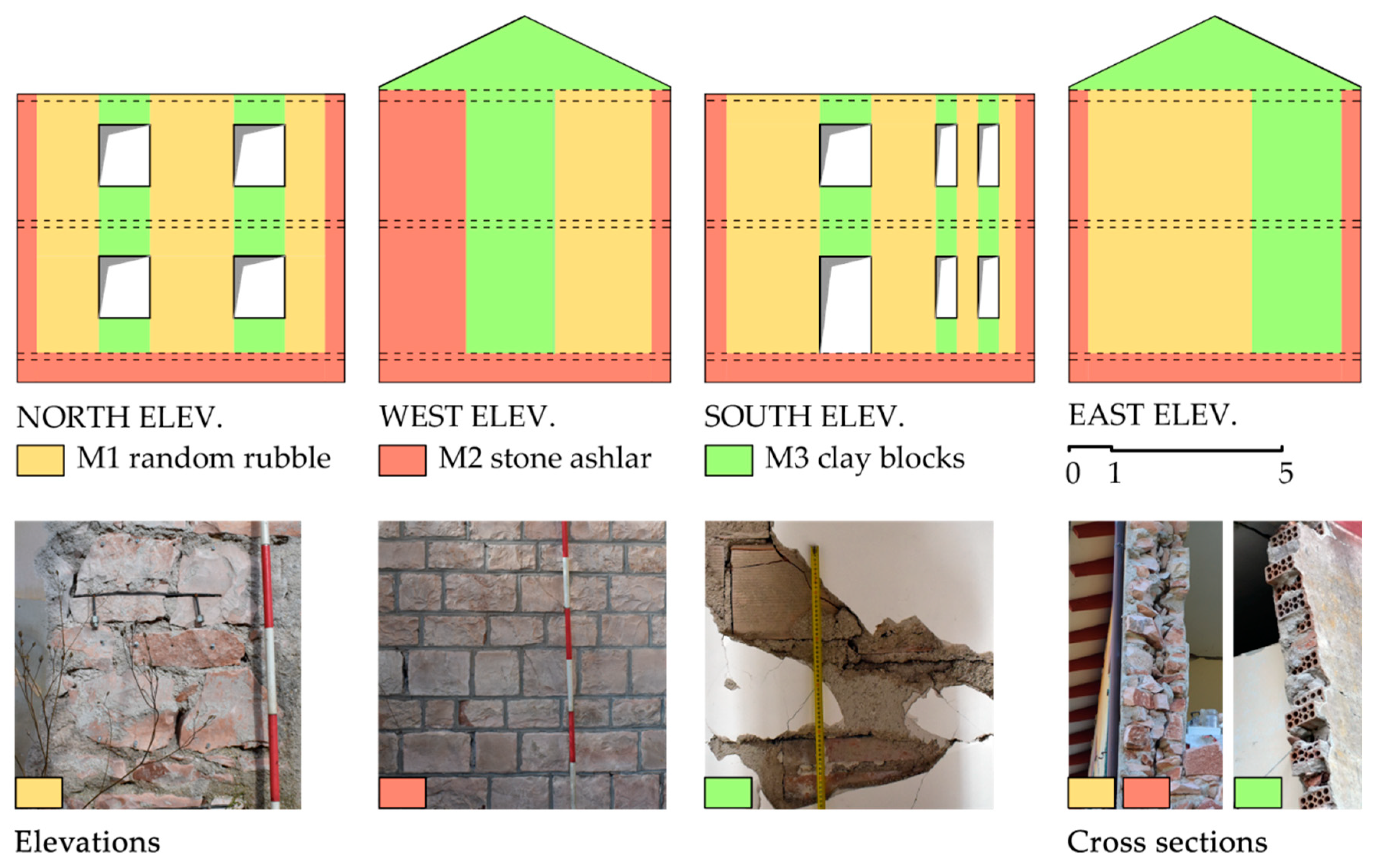
2.3. Structural Characterization

No structural and mechanical data about the bearing elements were available; all the structural features were taken from an onsite survey carried out by the authors in October 2018 and November 2019.
The foundations were not inspected; nonetheless, according to the practice of those times, they were supposed to consist of strips of poorly reinforced concrete.
Despite the simple architectural appearance, material usage in loadbearing walls was rather patchy. Walls are made of (see Figure 5): (a) 45-cm-thick random rubble limestone masonry (M1 type, yellow colour), (b) 45-cm-thick ashlar masonry (M2 type, red colour), and (c) 25-cm-thick hollow clay block masonry (M3 type, green colour); for all the masonry types, cement mortar was used to embed units. M3 masonry is used in the east and west walls, where the staircase is, in gables, in the internal wall at the ground floor, and in the spandrels of the north and south facades; the rest is made of either M1 or M2 masonries, depending on where the ashlar finish is. However, local crumbling of ashlar masonry revealed diamond-shaped stones and the same two-leaves section of M1 type; consequently, following a conservative and simplified approach to the model, the two types were considered as one (M1, see Section 2.5).
All masonry types appeared to have low mechanical performances, as, in M1 and M2, bond stones are missing and two leaves were evident from surveys; in M3, the percentage of voids is high, and blocks are laid with holes parallel to bed joints. However, this is a common feature of pre-standard block masonry walls [8,39].
Floor slabs are made of a clay block ribbed system sold in those times under the SAP acronym [40]. Blocks were aligned on the work site and bound with cement mortar, including steel rebars (Ø4 to Ø6) at the bottom and top faces so that the resulting joists could be mounted without formworks and scaffolding. The structural height of the blocks could vary from 8–12 cm (lofts and ceilings) to 16–20 cm (floor slabs), and concrete was poured just to fill the spaces left between the joists, as contemporary codes [41] allowed without any overlay. These slabs were usually bordered by an unreinforced concrete ring beam, which offered the support on the walls and the anchorage of the longitudinal reinforcement of the joists; indeed, these ring beams were evident during the surveys, owing to the seismic damage (Figure 6). Finally, the roof structure is also typical of those years, that is, precast r.c. joists supporting a hollow clay tile decking. These joists are exposed to shear failure, as they do not have a specific reinforcement [17].

2.4. Seismic Behaviour

In the absence of specific seismic design, the IACP building presents evident vulnerability factors, i.e., the overall irregular plan, the presence of slender piers, the closeness of windows to the building’s corners, the poor masonry quality, the potential flexibility and brittleness of floor and roof slabs, and the absence of transverse walls and of tensile-resistant elements in horizontal connections. Nevertheless, the response to the strongest event of the 2016 sequence was almost satisfactory (Figure 7). The observed damage, overall estimated in D3, i.e., moderate damage, according to the increasing damage scale D0–D5 in EMS-98 [33], was strongly oriented along the E–W direction, and consisted of:
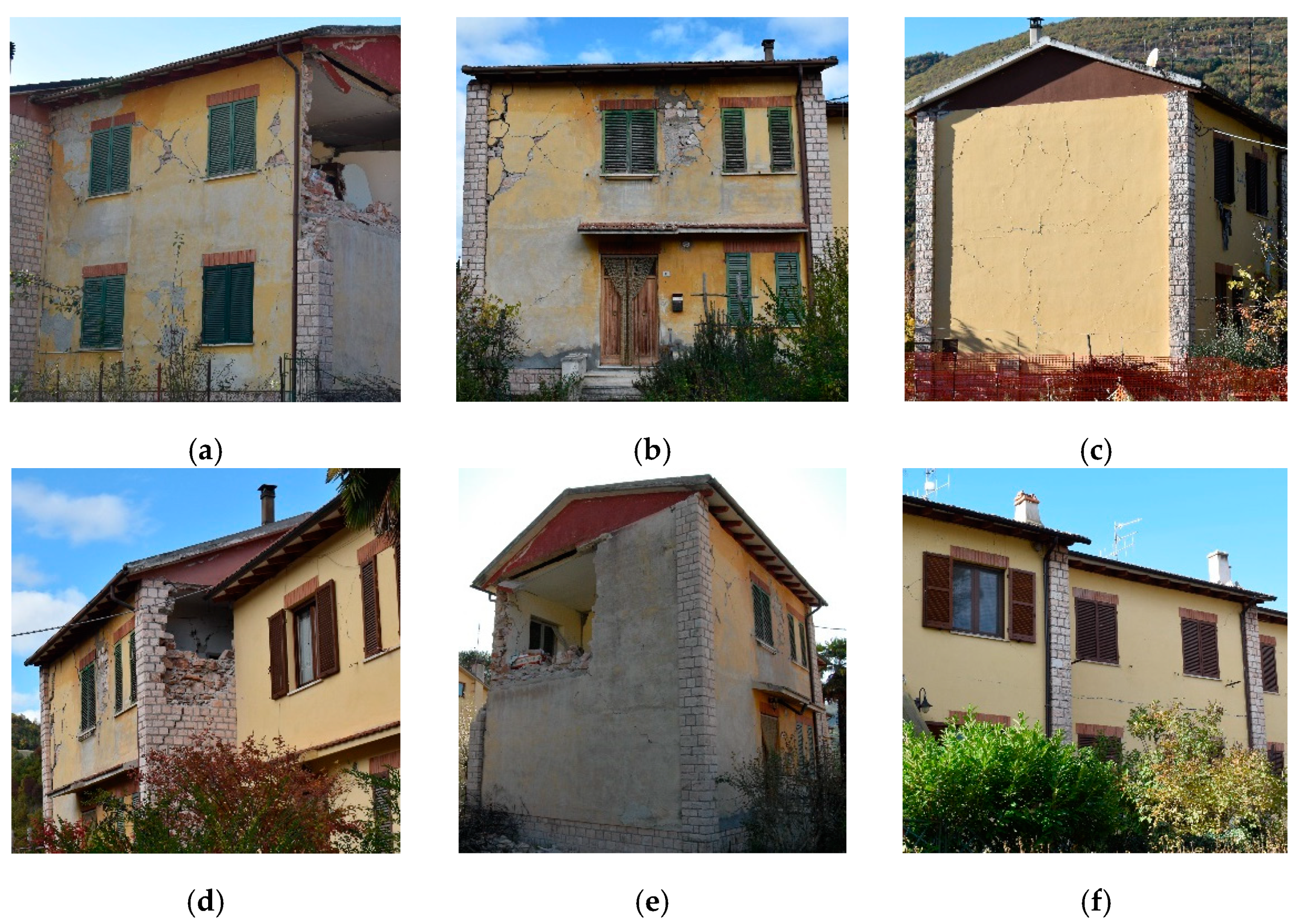
  • Diagonal shear damage in piers of the north, south, and east facades, heavier in the extreme units (no. 1 and 6) and in the upper storeys (Figure 8a–c);
  • Light flexural and/or crushing cracks in spandrels;
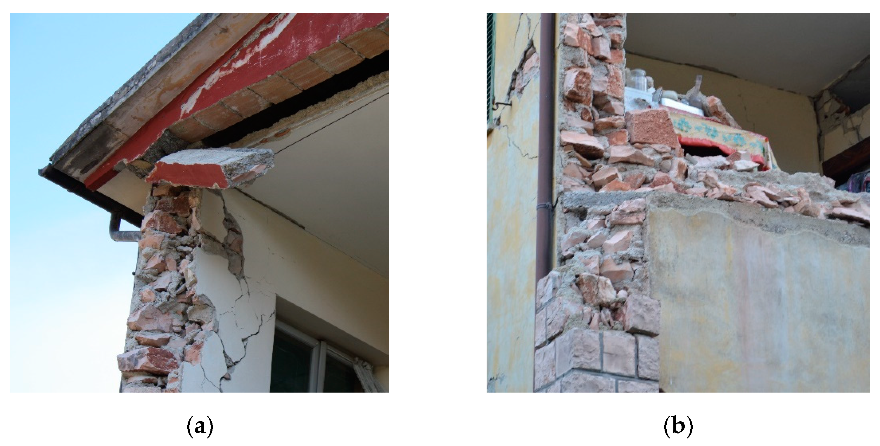
  • Local crumbling and OOP collapses of panels in the west and east facades of unit no. 6 (Figure 8d–e);
  • Activation of the overturning in the first storey of unit no. 6 in M3 masonry walls (Figure 8b) and shear cracks at the ground floor;
  • Shear failure of non-structural partitions and slight to moderate IP damage of internal loadbearing walls (although this datum is limited to a few units);
  • Sliding cracks at floor levels, mainly in internal units (Figure 8f).
Such behaviour confirmed the proneness of the extreme units to seismic damage. In spite of their reduced thickness, spandrels were stronger than piers. In addition, spandrels and floor slabs actively coupled piers. Consequently, the masonry piers, which would be slender according to their geometrical properties, showed diagonal rather than bending cracks. The observed behaviour confirmed that the mechanical properties of masonry were actually poor, but that a good connection among walls existed. The overturning mechanisms recall a masonry crumbling behaviour, which is compatible with the lacking of transversal connections between the leaves of M1 and M2 wall types.
As regards the diaphragms (i.e., roof and floor structures), they can commonly be considered prone to collapse despite their type. In this case, they offered a good performance, probably thanks to their narrow structural spans.
Overall, the IACP building’s seismic behaviour was hybrid, as semi-rigid diaphragms and r.c. ring beams allowed the IP behaviour of walls, but the poor masonry quality caused local collapses and heavy shear damage in loadbearing elements.
The IACP building’s real observed behaviour was considered as a reference for the calibration of the structural model (see Section 2.5) (a similar approach can also be found in [42]). The calibration procedure is summarized in the ‘supplementary material’ of this paper.

2.5. FME Modeling

The overall behaviour of both a single unit and the whole terrace was studied by means of a 3D model in the commercial version of 3Muri software [16] (Figure 9). This was justified by the predominant IP response observed after the 2016 seismic event, thanks to the presence of the strong spandrels and the semi-rigid diaphragms (see Section 2.4). In 3Muri, masonry walls with openings (i.e., doors and windows) are modelled in piers, bearing the vertical loads, and spandrels, which connect the piers through rigid nodes. Masonry panels are modelled as nonlinear beams with a piecewise relationship between the drift ratio and the horizontal force, which simulate the occurrence of flexural, shear, or mixed failure modes [43]. R.c. ring beams are modelled as nonlinear beams with elastoplastic hinges at the end sections, whose properties are determined by the criteria proposed in Italian and European codes [21,44]; diaphragms are modelled as membranes with equivalent thickness and stiffness.
Random rubble masonry mechanical properties (M1 type, to which M2 was also assimilated, see Section 2.4) were determined from [22]. Those of clay blocks (M3 type) were assumed at first from Messali et al. [45], who tested clay block masonry walls with horizontal holes, and then properly increased to make the damage state obtained in 3Muri match with the observed damage (i.e., diagonal shear of piers) (Figure 10). Table 1 shows the final reference values. The Turnšek–Čačovič shear failure criterion [46] was assumed for both rubble and block masonries.
The minimum knowledge level (KL = 1) and the confidence factor (CF = 1.35) were assumed for the building, according to [21,23]. In addition, to take into consideration the effect of the evident poor mechanical properties of the binder and the stiffness degradation induced by the seismic damage, both elastic moduli and strength properties of M1 and M3 were reduced to 40% and 70% of their values, respectively.
Yielding and ultimate strengths of steel rebars in the r.c. ring beams (fy = 357 MPa and fu = 519 MPa, respectively) were assumed according to data on buildings of a similar age [47]. The concrete compressive strength (fc = 20 MPa) was assumed in compliance with [41]. The CF = 1.35 was also applied to these properties.
In lack of specific testing on mechanical properties, the shear (G) and Young’s (E) moduli of the slabs were assumed from those of a hollow clay block masonry (minimum values according to [22]), as follows: E = 1200 MPa in both plan directions and G = 300 MPa. The former two govern the coupling of piers in the same wall, the latter that of perpendicular walls. The roof was not considered rigid in its plane; therefore, it was modelled by a vertical load acting on the upper storey of the building.
Structural loads (gk1) were determined according to building manuals [40]; non-structural loads (gk2) were considered for floors and roof only; on the first storey, a distributed load equivalent to non-structural partitions was added. Live loads (qk) were assumed according to [21], as well as the combination coefficients for seismic conditions (ψ2j) (Table 2).

2.6. Strenghtening Strategies

Each stage of the incremental procedure proposed in Figure 1 might include several intervention techniques whose application to a masonry building can provide various improvement effects.
For the IACP building, three strategies were proposed according to an increasing impact on a building’s usage continuity and on the expected structural performance in strengthened conditions (performance ratio ζE, see Section 1.2). Figure 11 shows the intervention techniques considered suitable for each target of improvement and their significant combinations for the building in question. Three levels of impact, i.e., minimum, low, and medium, were taken into consideration. Except for the need for an r.c. overlay of the roof, which is common to all cases:
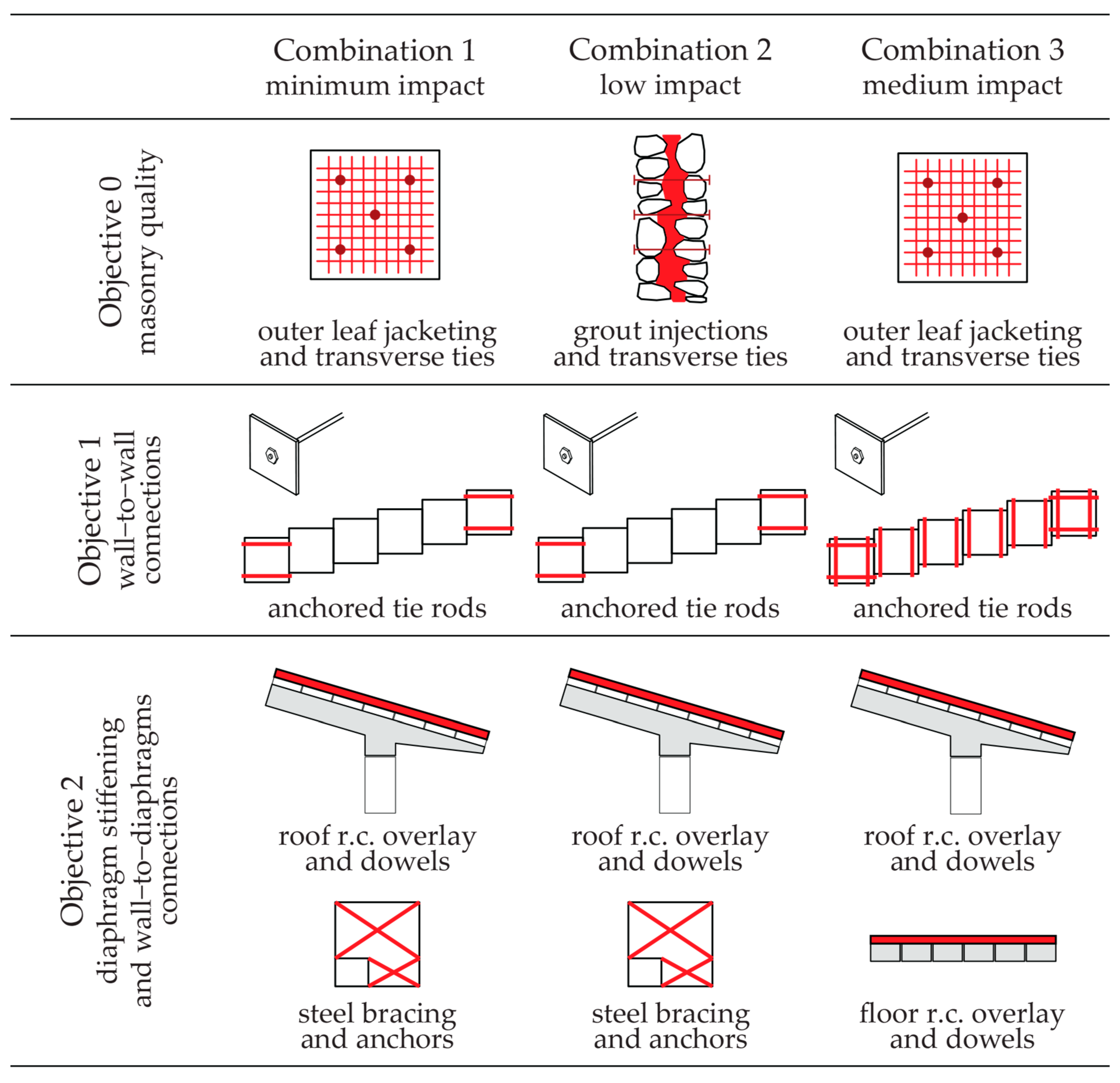
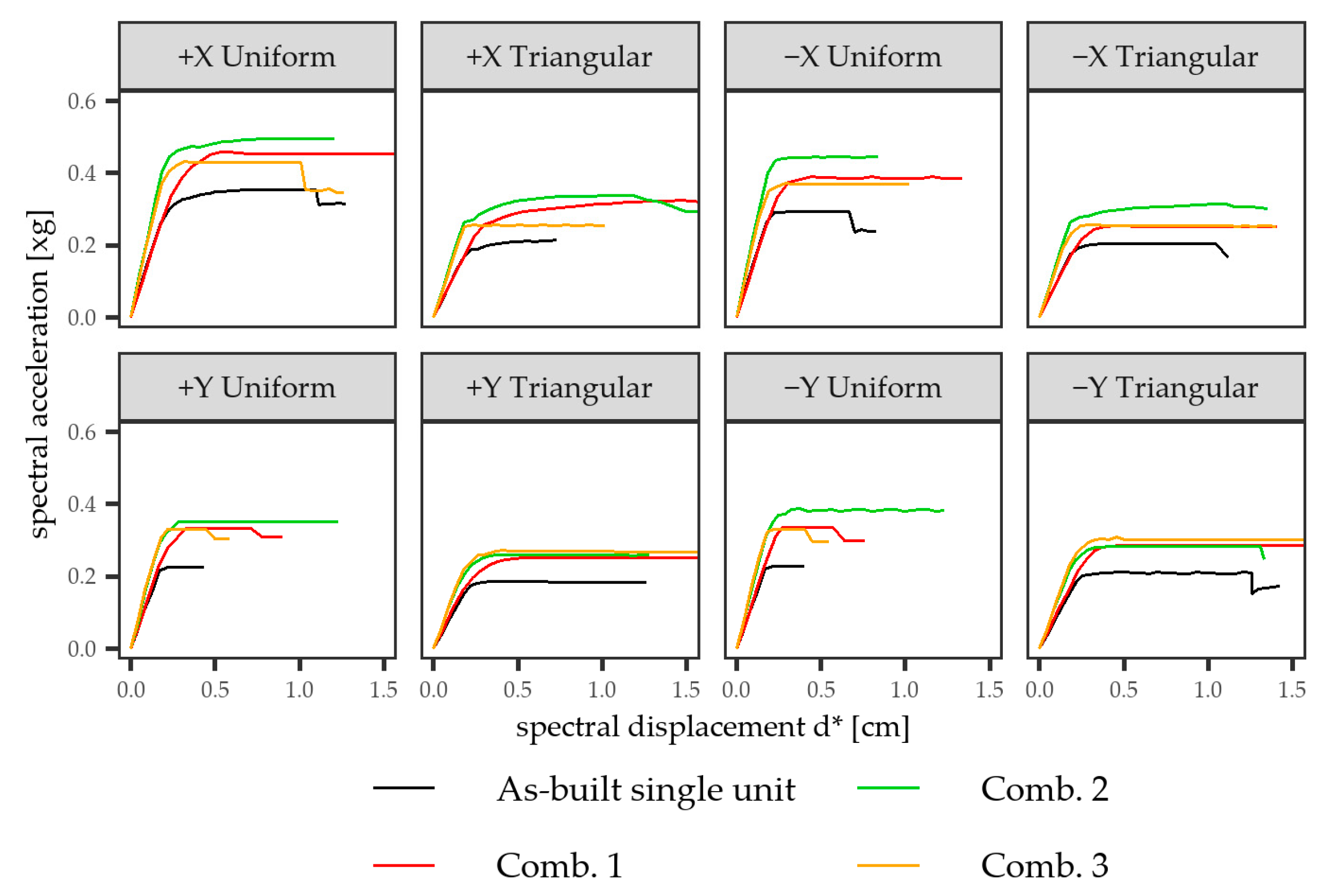
  • Combination 1 (minimum impact) refers to light interventions on both horizontal (bracing of floors at intrados) and vertical (innovative jacketing on masonry outer leaf only) components, and tying on extreme units only;
  • Combination 2 (low impact) adds the action on the building’s fabric by increasing the masonry compactness with grout injections;
  • Combination 3 (medium impact) acts in a similar way on diaphragms and differs from combination 1 in the r.c. overlay on the three floor slabs and the tying of all units.
In all cases, transverse ties and dowels are required to improve the connection between the masonry leaves and between diaphragms and walls, respectively.
Objective 0: as, originally, cement mortar was applied in IACP buildings’ walls, deep repointing [48] was considered useless; the improvement of masonry quality referred to the application of jacketing with fibre-reinforced cementitious matrix (FRCM) systems, only applied from the outside, or grout injections. Jacketing is an intervention frequently chosen to strengthen URM buildings thanks to its good structural performances [49,50]; however, in the case of installation to only one side of a wall, proper performance reduction factors need to be taken into consideration [51,52,53]. Grout injections are considered more intrusive than the one-side jacketing due to the more time-consuming installation procedure; in addition, the effectiveness of this technique needs to be properly checked by non-destructive investigations [54]. These interventions also targeted masonry’s mechanical strength, and, therefore, objective 3 (see Figure 1) was considered already satisfied in these cases.
Objective 1: wall-to-wall connection was improved through steel tie rods, properly anchored to the loadbearing walls, and placed either in just the extreme units along the X direction (combinations 1 and 2) or in both X and Y directions in all inner units (combination 3) to prevent OOP mechanisms.
Objective 2: wall-to-diaphragm connections were improved together with the stiffening of diaphragms. As for the roof, to avoid its replacement, an r.c. overlay connected through dowels to the existing joists was proposed in each combination. Floor slabs were reinforced through either steel bracings applied to their intrados (combinations 1 and 2) or an r.c. overlay, similar to that applied to the roof (combination 3). Dowels would be entrusted with the connection between the existing and the new slab, as well as between the overlay and walls.
However, the prevision of the structural behaviour of a strengthened building is not an easy task, especially in the case of existing masonry buildings, whose actual state is often hybridized by many changes that occurred over the course of time.
Strengthening interventions can either be explicitly or implicitly modelled: in the former case, analytical elements (e.g., beams, plates, links) simulate those parts that the techniques are composed of; in the latter, just their effect is considered, by properly increasing the mechanical properties of materials, e.g., according to those factors proposed by the Italian seismic code [22]. It is worth noting that these factors are only available for interventions on masonry walls and presume either the complete effectiveness of the technique or its favourable effect. Contributions in literature are still scarce on this topic. In [42], the simulation of improved wall-to-diaphragm connections, stiffening techniques applied to diaphragms with increasing levels of impact, deep joint repointing, and jacketing applied to masonry walls were performed by 3Muri software on three full-scale mock-ups reproducing rubble masonry buildings with timber diaphragms. The model was calibrated based on the outcomes of shake-table testing. The impracticality of explicitly modelling the retrofit details resulted in the adoption of the improvement factors suggested by [22].
In the case of the IACP building, each intervention was implemented both singularly and in combination with the others. The FRCM jacketing was modelled according to the formulations given by [51,55], applied to a lime mortar coating reinforced by a 33 × 33 mm2 GFRP mesh (glass-fibre-reinforced polymer); Table 3 lists its overall geometric and mechanical parameters. This reinforcement system was applied to both stone and clay block panels. Transverse ties connecting masonry leaves and grout injections were simulated by the multiplicative factors of 1.5 and 2.0, as suggested by [22] for random rubble masonry, respectively. These factors apply to strength parameters only (fm, τ0) for transverse ties and to both strength and elastic moduli (E, G) for grout injections.
Tie rods to counteract OOP effects on wall panels were calculated according to [56,57]. Four steel Ø16 bars, prestressed by 200 daN, were considered in the model, and their effect in OOP mechanisms was also separately evaluated (see Section 3.1.2).
The r.c. overlays were simulated by substituting the membranes equivalent to actual slabs with a completely rigid diaphragm and increasing the dead loads by 120 kg/m2. The steel bracing system was implemented with Ø16 steel bars with the same prestressing force as above.

3. Results and Discussion

3.1. Assessment of as-Built Conditions

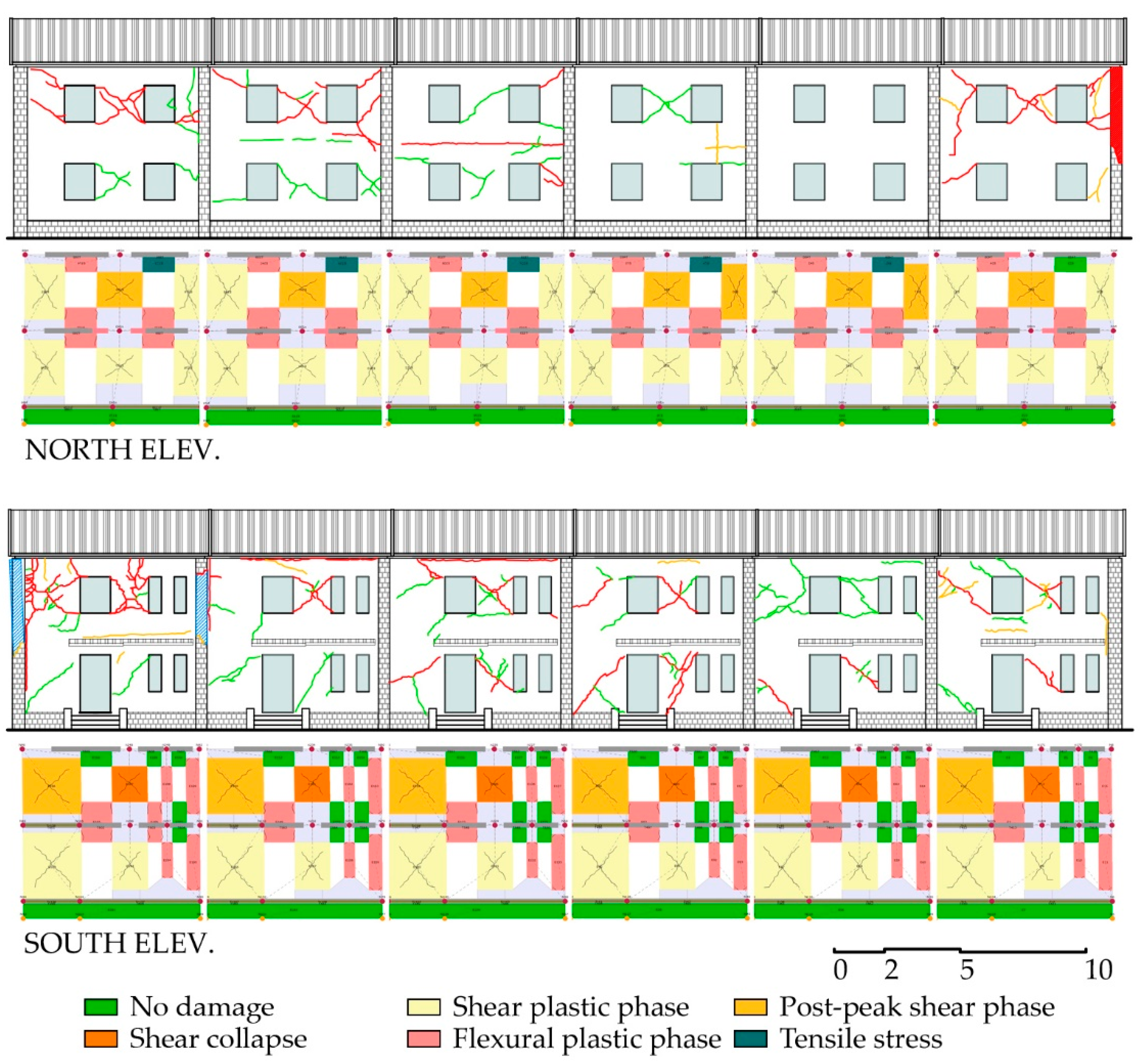
3.1.1. Overall Behaviour

Pushover analyses were carried out with either uniform or triangular distributions of horizontal loads, but without considering the accidental eccentricity between the centre of stiffness and masses as floor slabs are not completely rigid. The control node was chosen where the weakest external walls meet, in a corner of the unit (Figure 9), since slabs are not completely rigid in as-built conditions. Figure 12 shows the normalized pushover curves (spectral acceleration a* = F/Γm*, spectral displacement d* = d/Γ, where F is the total shear force at the base, d is the control node displacement, Γ is the modal participation factor, and m* the participating mass) of both the single-unit and the terrace model. The overall model was stronger than the single-unit one in the X direction, and vice versa in the Y one. Indeed, there was no proportionality in the maximum shear force between the single-unit and the terrace models, and this difference was more evident in the Y direction, as the structural irregularities were amplified in that direction. The displacement capacity was almost equal between the models, with the overall model slightly more ductile.
This behaviour was also confirmed by the performance ratio ζE value at the SD limit state, which was slightly higher in the single-unit model than in the overall one (0.379 and 0.283, respectively, see Section 3.2).

3.1.2. Local Behaviour

As the IACP building also showed local overturning mechanisms (see Section 2.4), the overall assessment was completed through kinematic analyses of the north, south, and west facades of the single-unit model, assuming the same loads and geometrical features considered in the numerical 3D model. Calculations were made under the hypotheses of: (i) no tensile strength; (ii) limited compressive strength (toe crushing); (iii) compactness of macroblocks during the overturning; and (iv) negligible friction between floor slabs and walls. The horizontal hinge was considered at the foot of the walls and at the first-floor level to take into account the building’s dynamic filtering in the definition of the seismic demand along its height [22]. Due to the simplifying hypotheses, the overturning activation coefficients c were very conservative: c ranges between 0.025 and 0.035 at the ground floor and 0.085 and 0.095 at the first storey. Therefore, nonlinear analyses could offer a more precise understanding of the walls’ behaviour through the computation of the displacement of each wall in both positions of hinges. In all walls, the limit displacement was about half their thickness, between 20 and 25 cm. Figure 13 shows the capacity curves obtained for the IACP building at SD limit state plotted over the demand spectra in the acceleration–displacement plane (Sa–Sd).
Each performance ratio was calculated in comparison with the expected PGA at the DL and SD limit states (Table 4). The capacities in both the linear and nonlinear field of the three facade walls were similar according to the hinge’s position, the general conditions being comparable among them, though the lowest values were obtained in the south facade, which was the most heavily loaded by floor slabs. The ground spectrum determined a displacement demand larger than that obtained from the overdamped floor spectrum by 50%, both at the ground and first levels; therefore, it governed the values of the performance ratio.

3.2. Assessment of Strengthened Conditions

Figure 14 and Figure 15 show the results of pushover analyses of the single-unit and the whole-terrace models, respectively, to which the strengthening strategies proposed in Section 2.6 were applied. Each strategy determined an increase in the normalized base shear force (a*), up to the 40% (combination 2). This increment was more evident in the analyses carried out in the X direction of the models if compared to those in the Y direction, where blind, and therefore stronger, walls already exist in as-built conditions. The structure’s ductility also increased, especially in the X direction (the maximum increase was obtained in combination 2). In the terrace model, combination 3 was more effective in the Y direction (i.e., the weakest one), owing to the increased diaphragm stiffness, which favoured the inertial redistribution among walls.
The effectiveness of interventions was evaluated in terms of ζE at the SD limit state as a difference from its value in the as-built conditions, assumed as a reference. The capacity PGA was calculated assuming the attainment of the corresponding limit displacement on the overall model, as defined in [22].
Table 5 shows the results obtained for each intervention singularly implemented within the as-built, single-unit model. The interventions on walls influenced the building’s seismic capacity more than those on diaphragms and connecting devices. As for walls, the highest performance referred to grout injections with a ζE increase (ΔζE) of 0.407 (+107%); the installation of one-side FRCM jacketing increased ζE by 0.183 (+48%), whereas transverse bars alone were not enough to achieve the minimum improvement target of 0.1 (see Figure 1). Nevertheless, the combination of transverse bars with FRCM or grout injections led to a ΔζE of 0.279 (+74%) and 0.457 (+121%), respectively.
The evaluation of the effectiveness of tie rods is not reliable in an FME model, as these are intended more as a link between piers and spandrels than as a wall-to-wall connection to inhibit the OOP mechanisms. Indeed, the increment of the overall model’s capacity was null, as a probable consequence of the already available in-plane stiffness of diaphragms; similar results were obtained with the IP floor-bracing system.
Owing to the moderate IP stiffness of floor slabs in the as-built condition, the interventions on diaphragms led to increments of ζE lower than 0.1, which may be considered as just local interventions (see Section 1.2). The application of an r.c. overlay affected the performance ratio by just 4% and 2% when applied either to the roof or the floors, respectively. According to the FME approach, this is probably due to the increment in the diaphragms’ weight, despite the improvement of the stiffness towards the box-like behaviour.
Table 6 shows the effects of the combinations of interventions implemented in both the single-unit and the whole-terrace models. For the overall model, the presence of rigid diaphragms (combination 3) led to a higher improvement compared to the simple bracing of floors (combination 1) (81% versus 118%). The redistribution of seismic forces granted by rigid diaphragms efficiently counterbalanced the effect of plan irregularity of the whole building. The highest increase in ζE was obtained for combination 2, owing to the effectiveness of grout injections, either for single-unit (111%) or whole-terrace (121%) models. The results of the single-unit model reflected those of the whole terrace, except for diaphragm stiffening, owing to the regular geometry of each unit.
With the only exception of combination 1 applied to the overall terrace model, all strategies increased ζE by 0.6, independently from the number of considered units; hence, these interventions may ensure an improvement of the seismic capacity of the IACP building according to the current regulations. Lastly, combination 2 for the single-unit model led to a ζE very close to 0.8; hence, it can even be considered as an upgrading intervention.
The same procedure was applied to OOP mechanisms, which cannot be taken into consideration by the numerical model and whose countermeasure was the application of tie rods to the loadbearing walls of IACP buildings. Ties were designed to withstand the PGA at the DL limit state and, therefore, ζE = 1 in strengthened conditions for both hinge positions in the overturning mechanism (see Section 3.1.2). The increase in the performance ratio ζE was relevant and equal to 0.70 on average (Table 7). The capacity curve with tie rods (Figure 16) is piecewise and shows a sudden drop where tie rods reach the yield displacement (conventionally assumed at 0.1%); as north and west facades have different spans, tie rods have different ultimate displacements in the two directions, which are even closer to the unit.

4. Conclusions

This work contributed to the evaluation of the effect of interventions proposed for a terraced masonry building located in Pieve Torina, Marche region, Italy. This case study is representative of common residential buildings built that lack anti-seismic prescriptions in moderate to high seismic hazard areas. The analysed building shows several vulnerabilities (e.g., irregular shape, multiple masonry types, poor detailing, semi-rigid diaphragms) and had a hybrid response to the Central Italy 2016 earthquake, consisting of limited OOP mechanisms and widespread IP shear damage in piers.
This case study resulted in the opportunity to explore the possible numerical modelling solutions of both a building’s structural behaviour and strengthening interventions according to recently updated codes and recommendations. Owing to the activation of a prevalent unitary (box-like) behaviour of the building, a commercial FME software was used, and the model was calibrated on the observed crack pattern. Both a single unit (i.e., the most damaged on the west extremity) and the whole terrace were modelled. Uncertainties on materials, detailing, and components of the building were clarified by the perusal of codes and manuals contemporary to the building’s construction, and compared to selected literature contributions. Nevertheless, the common simplifications assumed in the model and some limitations in a proper evaluation of the OOP effects on both damage and intervention counteractions (e.g., through tying) required the integration of kinematic analyses focused on local overturning mechanisms of walls. It is worth noting that the combination of numerical and analytical approaches is always strongly suggested for existing masonry buildings, especially when predictive assessment (i.e., in the absence of data on the actual behaviour under seismic actions) is needed.
The main outcomes of this study are:
(a)
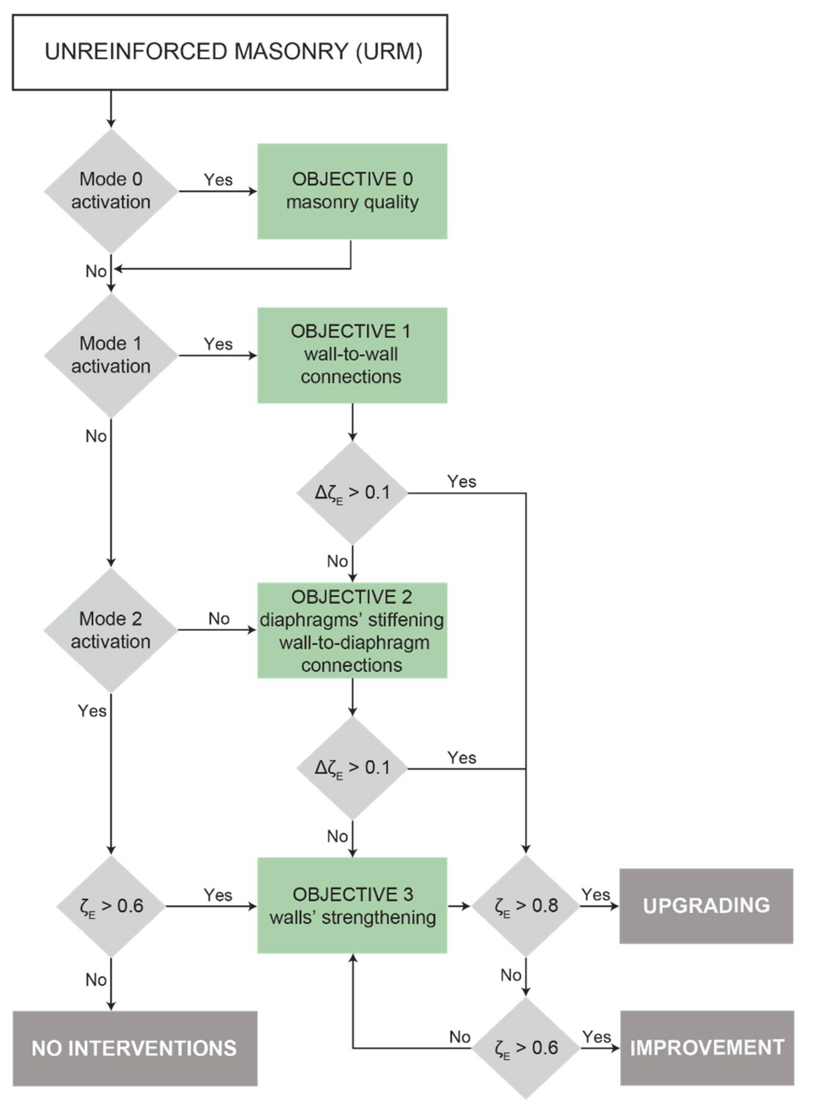
The requirements of recently passed seismic codes in Italy, in terms of both intervention techniques and quantification of the improvement, were organized in an incremental procedure, which combined structural behaviour (modes 0, 1, 2) with the respective targets to be achieved through interventions (objectives) and the corresponding performance ratios (ζE).
(b)
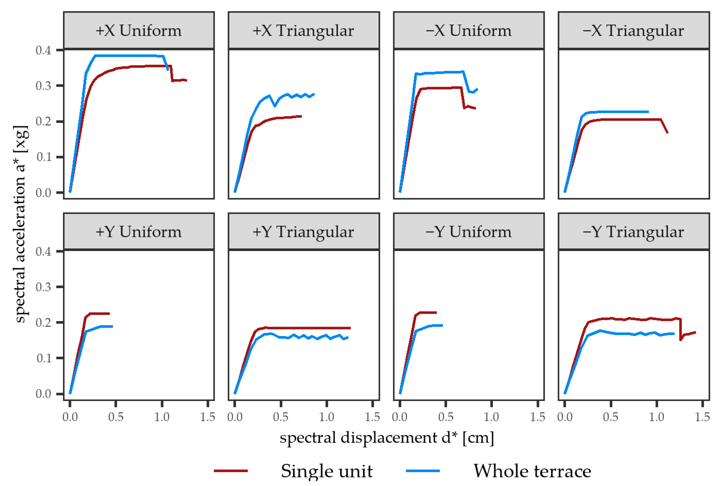
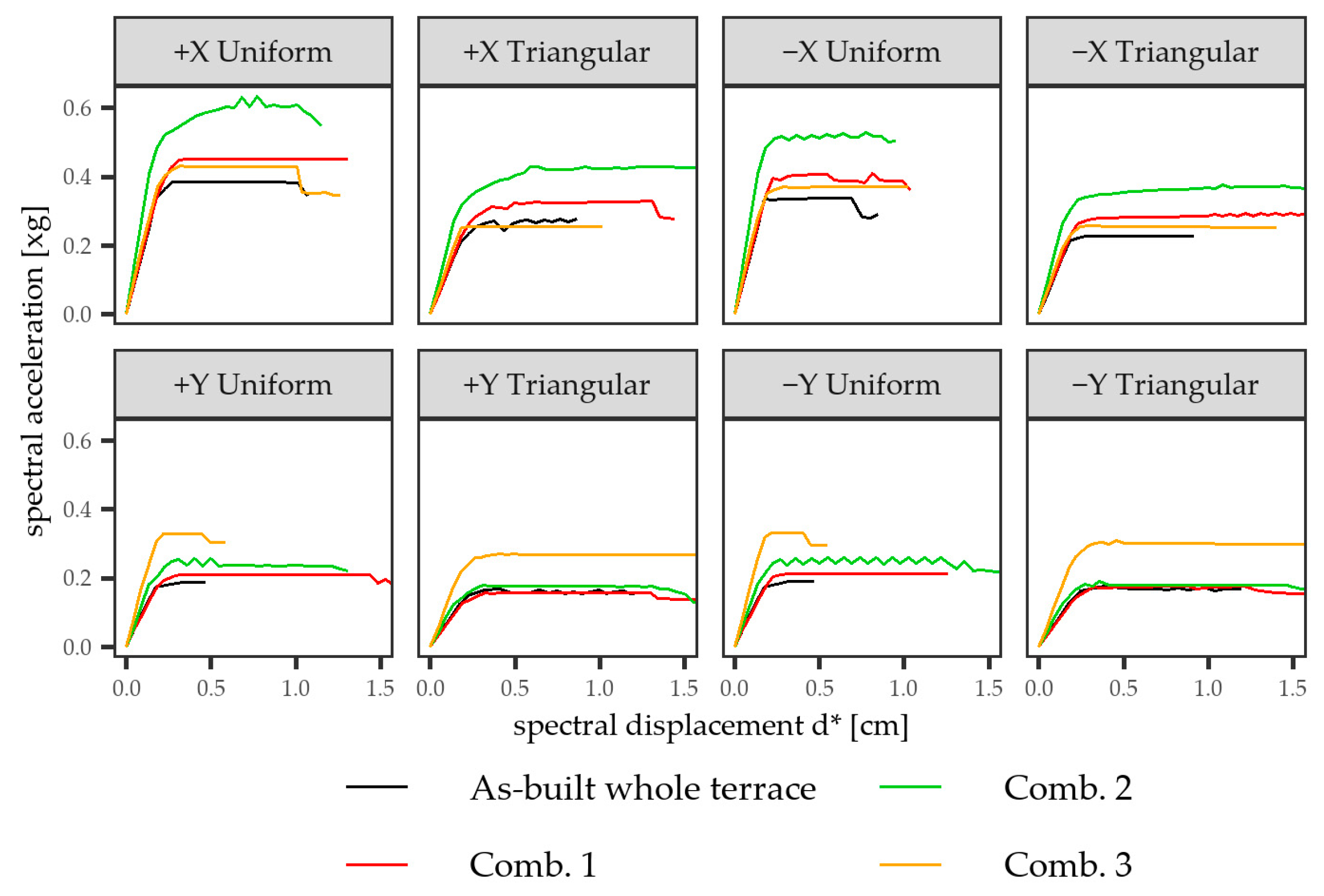
The comparison between the numerical results obtained for the single unit and the whole terrace for the as-built conditions highlighted the effect of irregularity of the overall building (ζE at the SD limit state reduced by about 25% for the whole terrace), particularly in the transverse (Y) direction.
(c)
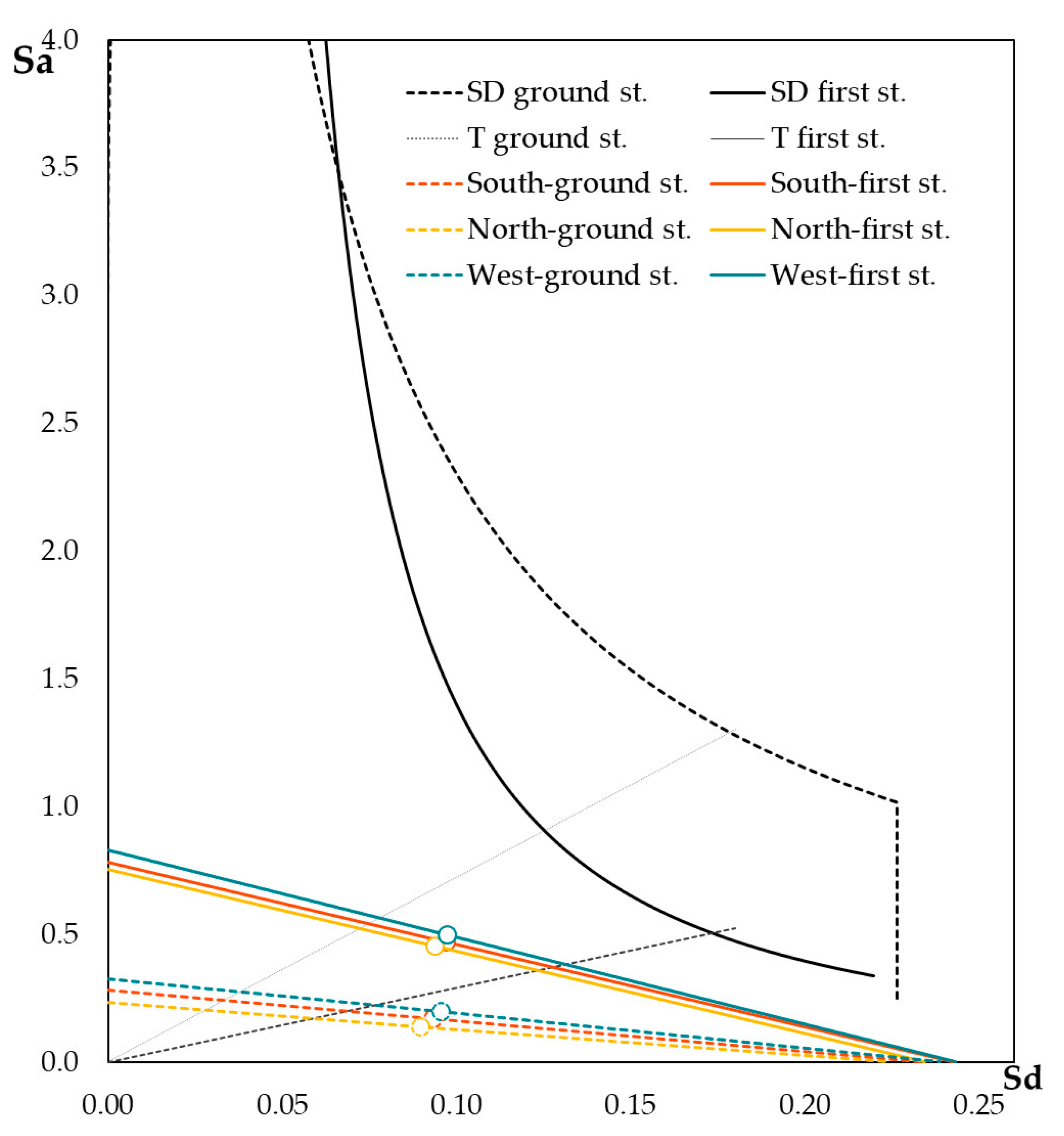
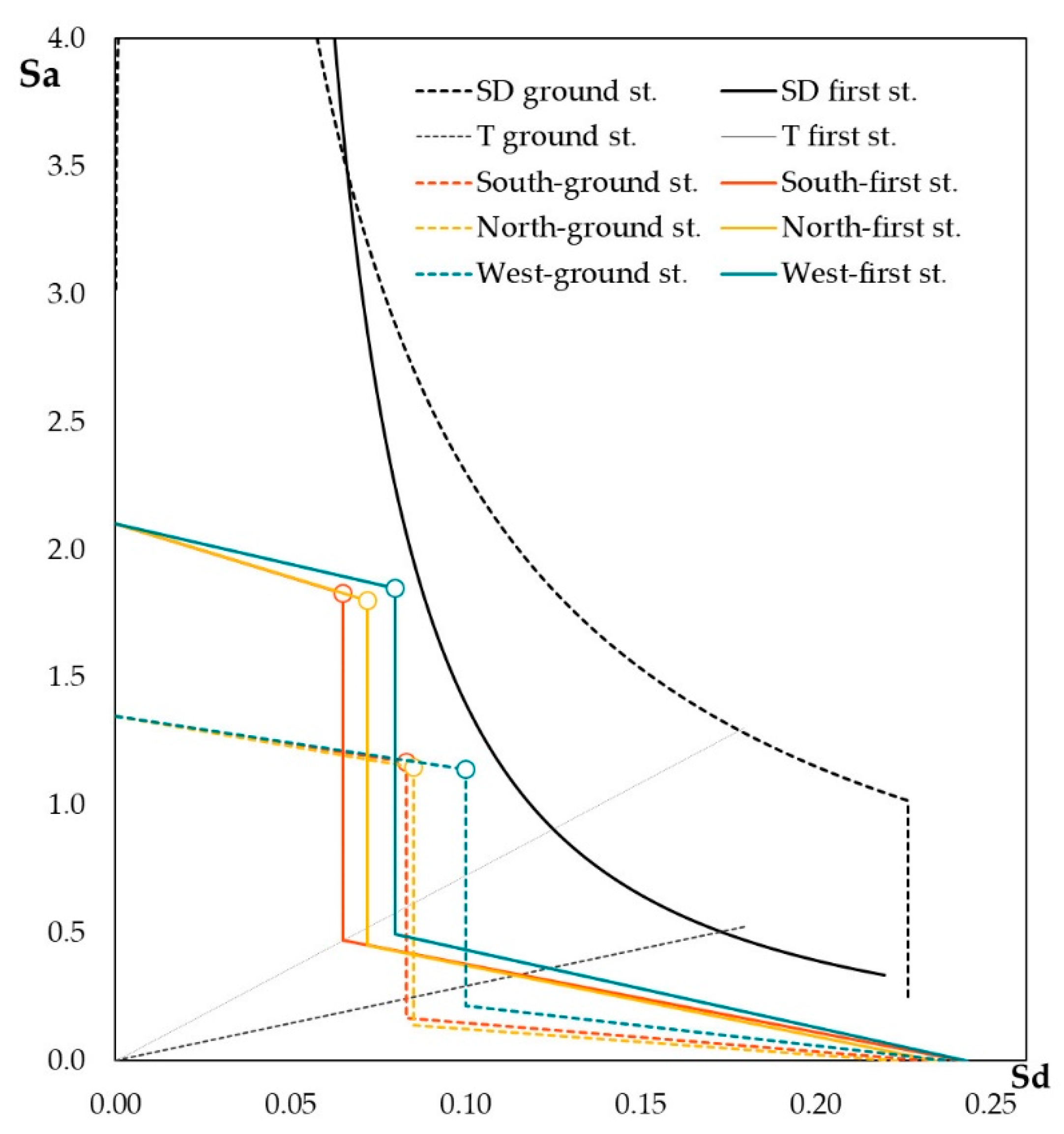
The local kinematic analysis was performed on the two levels (ground and first floors) of three facades of an extreme unit. The results, on average, did not vary according to the three walls and the two hinges’ positions and were rather conservative (i.e., the activation coefficient c ranged between a fifth and a half of the expected PGA); however, the capacity curves at SD limit state in the Sa–Sd plane indicated a displacement demand of the ground spectrum greater than that obtained from its floor formulation by 50%.
(d)
By excluding intrusive interventions (e.g., those with a high impact on usage continuity and demanding construction works, partial substitutions), three strengthening strategies with increasing impact (minimum, low, medium) were proposed. These included intervention techniques aimed at counteracting, progressively, a building’s seismic vulnerability towards an overall favourable behaviour.
(e)
For the case study, except for the unavoidable r.c. overlay of the roof, strengthening techniques referred to one-side installation (e.g., FRCM jacketing or grout injections for walls, steel bracing at intrados of floors or r.c. overlay, the latter limited to the highest impact combination) and the improvement of connections, either at overall (tie rods among opposite walls) or local (transverse ties in multi-leaf cross-sections of walls, dowels between diaphragms and walls) scale.
(f)
The effect of the individual intervention techniques on the performance of the single-unit model was particularly evident for grout injections: ζE at the SD limit state increased by 107% in comparison with the as-built conditions, and it was more than twice than that of the FRCM jacketing. Transverse ties applied to improve connections among masonry leaves had a minimum effect, and alone they were not sufficient to reach the target improvement defined by the code. Neither did stiffening interventions on diaphragms affect the performance of the single unit, and did not attain, if not in combination with the wall’s enhancement, the minimum requirement for improvement.
(g)
All combination cases, indeed, for either the single unit or the whole terrace, presented a good increase in ζE (over 0.6 for almost all the cases); this confirmed the reliability of the incremental procedure and, at the same time, offered an opportunity to quantify the actual improvement as a guide for the choice of a building’s strengthening techniques.
Further developments of this study will focus on open issues on the contribution of strengthening solutions according to various modelling approaches. Cost analyses would also complete the evaluation of the impact of the intervention strategies.

Supplementary Materials

The Supplementary Materials are available online at https://www.mdpi.com/article/10.3390/buildings11090404/s1.

Author Contributions

Conceptualization, methodology, investigation, writing—original draft preparation, writing—review and editing: M.R.V., L.S., Y.S.; validation, formal analysis, data curation, visualization: L.S., Y.S.; supervision, resources, project administration, funding acquisition: M.R.V. All authors have read and agreed to the published version of the manuscript.

Funding

This research was carried out in the framework of the 2019–2021 DPC-ReLUIS Project (Italian Civil Protection Department—Laboratories University Network of Seismic Engineering).

Acknowledgments

The authors wish to thank C. Bernardinello and M. Fabris for their help during the onsite survey.

Conflicts of Interest

The authors declare no conflict of interest. The funders had no role in the design of the study; in the collection, analyses, or interpretation of data; in the writing of the manuscript, or in the decision to publish the results.

References

  1. Economidou, M.; Atanasiu, B.; Despret, C.; Maio, J.; Nolte, I.; Rapf, O. Europe’s Buildings under the Microscope. A Country-by-Country Review of the Energy Performance of Buildings; Buildings Performance Institute Europe (BPIE): Brussels, Belgium, 2011. [Google Scholar]
  2. Tsionis, G.; Apostolska, R.; Taucer, F. Seismic Strengthening of RC Buildings; EUR 26945; Publications Office of the European Union: Luxembourg, 2014; p. JRC91949. [Google Scholar] [CrossRef]
  3. Da Porto, F.; Donà, M.; Rosti, A.; Rota, M.; Lagomarsino, S.; Cattari, S.; Borzi, B.; Onida, M.; De Gregorio, D.; Perelli, F.L.; et al. Comparative analysis of the fragility curves for Italian residential masonry and RC buildings. Bull. Earthq. Eng. 2021, 19, 3209–3252. [Google Scholar] [CrossRef]
  4. ISTAT Italian National Institute of Statistics. 2011. Available online: https://www.istat.it/it/archivio/104317 (accessed on 1 June 2021).
  5. Giardini, D.; Wössner, J.; Danciu, L. Mapping Europe’s Seismic Hazard. EOS 2014, 95, 261–262. [Google Scholar] [CrossRef] [Green Version]
  6. President of the Council of Ministers. Primi Elementi in Materia di Criteri Generali per la Classificazione Sismica del Territorio Nazionale e di Normative Tecniche per le Costruzioni in Zona Sismica; Ordinance: Rome, Italy, 2003. (In Italian) [Google Scholar]
  7. Stucchi, M.; Meletti, C.; Montaldo, V.; Crowley, H.; Calvi, G.M.; Boschi, E. Seismic Hazard Assessment (2003–2009) for the Italian Building Code. Bull. Seism. Soc. Am. 2011, 101, 1885–1911. [Google Scholar] [CrossRef]
  8. Valluzzi, M.R.; Sbrogiò, L.; Saretta, Y.; Wenliuhan, H. Seismic Response of Masonry Buildings in Historical Centres Struck by the 2016 Central Italy Earthquake. Impact of Building Features on Damage Evaluation. Int. J. Arch. Herit. 2021, 1–26. [Google Scholar] [CrossRef]
  9. Kallioras, S.; Graziotti, F.; Penna, A. Numerical assessment of the dynamic response of a URM terraced house exposed to induced seismicity. Bull. Earthq. Eng. 2019, 17, 1521–1552. [Google Scholar] [CrossRef]
  10. Valluzzi, M.R.; Cardani, G.; Saisi, A.; Binda, L.; Modena, C. Study of the seismic vulnerability of complex masonry buildings. In Proceedings of the 9th International Conference on Structural Studies, Repairs and Maintenance of Heritage Architecture, Msida, Malta, 22–24 June 2005; pp. 301–310. [Google Scholar] [CrossRef]
  11. Binda, L.; Anzani, A.; Cardani, G. Methodologies for the evaluation of seismic vulnerability of complex masonry buildings: Case histories in the historic centre of Sulmona. In Heritage Masonry–Materials and Structures; Syngellakis, S., Ed.; WIT Press: Southampton, UK, 2014. [Google Scholar]
  12. Maio, R.; Vicente, R.; Formisano, A.; Varum, H. Seismic vulnerability of building aggregates through hybrid and indirect assessment techniques. Bull. Earthq. Eng. 2015, 13, 2995–3014. [Google Scholar] [CrossRef] [Green Version]
  13. Grillanda, N.; Valente, M.; Milani, G.; Chiozzi, A.; Tralli, A. Advanced numerical strategies for seismic assessment of historical masonry aggregates. Eng. Struct. 2020, 212, 110441. [Google Scholar] [CrossRef]
  14. Valente, M.; Milani, G.; Grande, E.; Formisano, A. Historical masonry building aggregates: Advanced numerical insight for an effective seismic assessment on two row housing compounds. Eng. Struct. 2019, 190, 360–379. [Google Scholar] [CrossRef]
  15. Tomaževič, M.; Bosiljkov, V.; Weiss, P. Structural behavior factor for masonry structures. In Proceedings of the 13th World Con-ference on Earthquake Engineering, Vancouver, BC, Canada, 1–6 August 2004; p. 2642. [Google Scholar]
  16. Lagomarsino, S.; Penna, A.; Galasco, A.; Cattari, S. TREMURI program: An equivalent frame model for the nonlinear seismic analysis of masonry buildings. Eng. Struct. 2013, 56, 1787–1799. [Google Scholar] [CrossRef]
  17. Saretta, Y.; Sbrogiò, L.; Valluzzi, M.R. Seismic response of masonry buildings in historical centres struck by the 2016 Central Italy earthquake. Calibration of a vulnerability model for strengthened conditions. Constr. Build. Mater. 2021, 299, 123911. [Google Scholar] [CrossRef]
  18. Sbrogiò, L.; Saretta, Y.; Valluzzi, M.R. Empirical performance levels of strengthened masonry buildings struck by 2016 Central Italy earthquake: Proposal of a new taxonomy. Int. J. Archit. Herit. submitted.
  19. Sisti, R.; Di Ludovico, M.; Borri, A.; Prota, A. Damage assessment and the effectiveness of prevention: The response of ordinary unreinforced masonry buildings in Norcia during the Central Italy 2016–2017 seismic sequence. Bull. Earthq. Eng. 2019, 17, 5609–5629. [Google Scholar] [CrossRef]
  20. Sorrentino, L.; Cattari, S.; Da Porto, F.; Magenes, G.; Penna, A. Seismic behaviour of ordinary masonry buildings during the 2016 central Italy earthquakes. Bull. Earthq. Eng. 2019, 17, 5583–5607. [Google Scholar] [CrossRef] [Green Version]
  21. Ministry of Infrastructures and Transportations. Ministerial Decree 17/01/2018. Aggiornamento delle ‘Norme Tecniche per le Costruzioni’. 2018. Available online: https://www.gazzettaufficiale.it/eli/id/2018/2/20/18A00716/sg (accessed on 30 June 2021). (In Italian)
  22. Ministry of Infrastructures and Transportations. Regulation n. 7/2019. Istruzioni per L’applicazione dell’Aggiornamento delle “Norme Tecniche per le Costruzioni” di cui al Decreto Ministeriale 17 Gennaio. 2018. Available online: https://www.gazzettaufficiale.it/eli/id/2019/02/11/19A00855/sg (accessed on 30 June 2021). (In Italian)
  23. European Committee for Standardization. Eurocode 8: Design of Structures for Earthquake Resistance–Part 3: Assessment and Retrofitting of Buildings; CEN: Brussels, Belgium, 2005. [Google Scholar]
  24. Ministry of Infrastructures and Transportations. Ministerial Decree 07/03/2017, Linee Guida per la Classificazione del Rischio Sismico delle Costruzioni; Ministry of Infrastructures and Transportations: Rome, Italy, 2017. (In Italian)
  25. Cosenza, E.; Del Vecchio, C.; Di Ludovico, M.; Dolce, M.; Moroni, C.; Prota, A.; Renzi, E. The Italian guidelines for seismic risk classification of constructions: Technical principles and validation. Bull. Earthq. Eng. 2018, 16, 5905–5935. [Google Scholar] [CrossRef]
  26. Abrams, D.P.; AlShawa, O.; Lourenço, P.B.; Sorrentino, L. Out-of-plane seismic response of unreinforced masonry walls: Conceptual discussion, research needs, and modeling issues. Int. J. Archit. Herit. 2017, 11, 22–30. [Google Scholar] [CrossRef]
  27. ICOMOS. Charter of Cracow. Principles for Conservation and Restoration of Built Heritage; ICOMOS: Paris, France, 2000. [Google Scholar]
  28. ICOMOS. ICOMOS Charter—Principles for the Analysis, Conservation and Structural Restoration of Architectural Heritage; ICOMOS: Paris, France, 2003. [Google Scholar]
  29. Tomaževič, M. Earthquake-Resistant Design of Masonry Buildings. Innovation in Structures and Construction; Imperial College Press: London, UK, 1999. [Google Scholar]
  30. Baggio, C.; Bernardini, A.; Colozza, R.; Corazza, L.; Dalla Bella, M.; Pasquale, G.D.; Dolce, M.; Goretti, A.; Martinelli, A.; Orsini, G.; et al. Field Manual for Post-Earthquake Damage and Safety Assessment and Short-Term Counter-Measures (AeDES); Pinto, A.V., Taucer, F., Eds.; EU JRC: Luxembourg, 2007. [Google Scholar]
  31. Valluzzi, M.R.; Sbrogiò, L. Vulnerability of architectural heritage in seismic area: Constructive aspects and effect of interventions. In Cultural Landscape in Practice. Conservation vs. Emergencies; Amoruso, G., Salerno, E., Eds.; Springer: Berlin/Heidelberg, Germany, 2019; pp. 203–218. [Google Scholar] [CrossRef]
  32. Corradini, S. La Pieve ed i Castelli. Appunti per la Storia del Territorio; Micheloni: Recanati, Italy, 1979; pp. 86–182. (In Italian) [Google Scholar]
  33. Grünthal, G. European Macroseismic Scale 1998. Cahiers du Centre Européen de Géodynamique et de Séismologie, 15; European Center for Geodynamics and Seismology: Luxembourg, 1998. [Google Scholar]
  34. Locati, M.; Camassi, R.; Rovida, A.; Ercolani, E.; Bernardini, F.; Castelli, V.; Caracciolo, C.H.; Tertulliani, A.; Rossi, A.; Azzaro, R.; et al. Italian Macroseismic Database (DBMI15), Version 3.0 2021, 3228 Earthquakes, 123956 Macroseismic Data Points; INGV: Rome, Italy, 2019. [Google Scholar]
  35. Lenzi, U.; Lenzi, A.; Pinti, S. Microzonazione Sismica, Relazione Illustrativa; Regione Marche, Comune di Pieve Torina; Municipality of Pieve Torina: Regione Marche, Italy, 2018. (In Italian) [Google Scholar]
  36. Sextos, A.; De Risi, R.; Pagliaroli, A.; Foti, S.; Passeri, F.; Ausilio, E.; Cairo, R.; Capatti, M.C.; Chiabrando, F.; Chiaradonna, A.; et al. Local Site Effects and Incremental Damage of Buildings during the 2016 Central Italy Earthquake Sequence. Earthq. Spectra 2018, 34, 1639–1669. [Google Scholar] [CrossRef] [Green Version]
  37. Stucchi, M.; Meletti, C.; Montaldo, V.; Akinci, A.; Faccioli, E.; Gasperini, P.; Malagnini, L.; Valensise, G. Pericolosità Sismica di Riferimento per il Territorio Nazionale MPS04; INGV: Rome, Italy, 2004. [Google Scholar]
  38. Ministry of Public Works. Ministerial Decree 10/02/1983, Aggiornamento delle Zone Sismiche della Regione Marche; Ministry of Public Works: Rome, Italy, 1983. (In Italian)
  39. Borri, A.; Corradi, M.; De Maria, A. The Failure of Masonry Walls by Disaggregation and the Masonry Quality Index. Heritage 2020, 3, 1162–1198. [Google Scholar] [CrossRef]
  40. AA.VV. Manualetto RDB; RDB: Piacenza, Italy, 1982. (In Italian) [Google Scholar]
  41. Italian Royal Decree No. 2229, 03/04/1930, Norme per L’esecuzione delle Opere in Conglomerato Cementizio Semplice od Armato. 1939. (In Italian)
  42. Guerrini, G.; Salvatori, C.; Senaldi, I.; Penna, A. Experimental and Numerical Assessment of Seismic Retrofit Solutions for Stone Masonry Buildings. Geosciences 2021, 11, 230. [Google Scholar] [CrossRef]
  43. Cattari, S.; Lagomarsino, S. Seismic assessment of mixed masonry-reinforced concrete buildings by non-linear static analyses. Earthq. Struct. 2013, 4, 241–264. [Google Scholar] [CrossRef] [Green Version]
  44. European Committee for Standardization. Eurocode 2: Design of Concrete Structures-Part 1-1: General Rules and Rules for Buildings; CEN: Brussels, Belgium, 2004. [Google Scholar]
  45. Messali, F.; Metelli, G.; Plizzari, G. Experimental results on the retrofitting of hollow brick masonry walls with reinforced high performance mortar coatings. Constr. Build. Mater. 2017, 141, 619–630. [Google Scholar] [CrossRef]
  46. Turnšek, V.; Čačovič, F. Some experimental results on the strength of brick masonry walls. In Proceedings of the 2nd Int Brick Masonry Conference, Stoke-on-Trent, UK, 12–15 April 1970; pp. 149–156. [Google Scholar]
  47. Ricci, P.; Verderame, G.M.; Manfredi, G. Analisi statistica delle proprietà meccaniche degli acciai da cemento armato utilizzati tra il 1950 e il 1980. In Proceedings of the L’ingegneria sismica in Italia, XIV Convegno ANIDIS, Bari, Italy, 18–22 September 2011. (In Italian). [Google Scholar]
  48. Corradi, M.; Tedeschi, C.; Binda, L.; Borri, A. Experimental evaluation of shear and compression strength of masonry wall before and after reinforcement: Deep repointing. Constr. Build. Mater. 2008, 22, 463–472. [Google Scholar] [CrossRef] [Green Version]
  49. Valluzzi, M.R.; Binda, L.; Modena, C. Experimental and analytical studies for the choice of repair techniques applied to historic buildings. Mater. Struct. 2002, 35, 285–292. [Google Scholar] [CrossRef]
  50. ACI 549.6R-20. Guide to Design and Construction of Externally Bonded Fabric-Reinforced Cementitious Matrix (FRCM) and Steel-Reinforced Grout (SRG) Systems for Repair and Strengthening Masonry Structures; ACI: Farmington Hills, MI, USA, 2020. [Google Scholar]
  51. CNR-DT 215/2018. Advisory Committee on Technical Recommendations for Construction. Guide for the Design and Construction of Externally Bonded Fibre Reinforced Inorganic Matrix Systems for Strengthening Existing Structures; CNR: Rome, Italy, 2020. [Google Scholar]
  52. Ferretti, F.; Incerti, A.; Ferracuti, B.; Mazzotti, C. FRCM Strengthened Masonry Panels: The Role of Mechanical Anchorages and Symmetric Layouts. Key Eng. Mater. 2017, 747, 334–341. [Google Scholar] [CrossRef]
  53. Del Zoppo, M.; Di Ludovico, M.; Prota, A. Analysis of FRCM and CRM parameters for the in-plane shear strengthening of different URM types. Compos. Part B Eng. 2019, 171, 20–33. [Google Scholar] [CrossRef]
  54. Valluzzi, M.R.; Cescatti, E.; Cardani, G.; Cantini, L.; Zanzi, L.; Colla, C.; Casarin, F. Calibration of sonic pulse velocity tests for detection of variable conditions in masonry walls. Constr. Build. Mater. 2018, 192, 272–286. [Google Scholar] [CrossRef]
  55. CNR-DT 200 R1/2013. Advisory Committee on Technical Recommendations for Construction. Guide for the Design and Construction of Externally Systems for Strengthening Existing Structures; CNR: Rome, Italy, 2014. [Google Scholar]
  56. Pisani, M.A. Theoretical approach to the evaluation of the load-carrying capacity of the tie rod anchor system in a masonry wall. Eng. Struct. 2016, 124, 85–95. [Google Scholar] [CrossRef]
  57. Podestà, S.; Scandolo, L. Earthquakes and Tie-Rods: Assessment, Design, and Ductility Issues. Int. J. Arch. Herit. 2019, 13, 329–339. [Google Scholar] [CrossRef]
Figure 1. Incremental procedure for selection and evaluation of interventions on masonry buildings according to expected seismic performances.
Buildings 11 00404 g001
Figure 2. Pieve Torina: overview with village plan, soil amplification factors, structural and functional types of buildings, and location of case study. Key to numbers: (1) oldest nuclei; (2) 18th century building aggregates; (3) 20th century and recent buildings.
Buildings 11 00404 g002
Figure 3. External view of IACP building before earthquake (adapted from Google Earth).
Buildings 11 00404 g003
Figure 4. Geometrical survey of IACP building.
Buildings 11 00404 g004
Figure 5. Distribution of masonry types within IACP building.
Buildings 11 00404 g005
Figure 6. Details of unreinforced ring beams at (a) ceiling and (b) floor levels.
Buildings 11 00404 g006
Figure 7. Overview of seismic damage of IACP building.
Buildings 11 00404 g007
Figure 8. Details of damage pattern in IACP building: diagonal shear cracks of piers in (a) north and (b) south facades of unit no. 6, and activation of overturning in west facade; (c) shear cracks in east facade of unit no. 1; crumbling and overturning in (d) east and (e) west facades of unit no. 6; (f) sliding cracks at floor level in unit no. 4.
Buildings 11 00404 g008
Figure 9. FME model, southeast 3D view: (a) single-unit model (unit no. 6); (b) whole terrace. Key to colour: piers in orange, spandrels in green, rigid nodes in blue. Black dot indicates control nodes for single-cell and whole terrace analyses, respectively (see Section 3.1.1).
Buildings 11 00404 g009
Figure 10. Comparison between damage state obtained from modelling and observed crack pattern.
Buildings 11 00404 g010
Figure 11. Summary of three combinations (i.e., strategies) of interventions proposed for IACP building.
Buildings 11 00404 g011
Figure 12. Normalized pushover analyses of as-built models (single unit and whole terrace).
Buildings 11 00404 g012
Figure 13. Capacity curves of local mechanisms and demand spectra at ground and first floors (empty dots represent displacement capacity at SD limit state; radial lines indicate structure’s period T at displacement capacity).
Buildings 11 00404 g013
Figure 14. Single-unit model: normalized pushover analyses in strengthened conditions, compared to as-built.
Buildings 11 00404 g014
Figure 15. Whole-terrace model: normalized pushover analyses in strengthened conditions, compared to as-built.
Buildings 11 00404 g015
Figure 16. Capacity curves of local mechanisms with tie rods and demand spectra at ground and first floors (empty dots represent the displacement capacity at SD limit state; radial lines indicate the structure’s period T at displacement capacity).
Buildings 11 00404 g016
Table 1. Mechanical properties of masonry (values of elastic properties and strength to be reduced to 40% and 70%, respectively, and divided by CF).
MaterialCompressive Strength
fm (MPa)
Shear Strength
τ0 (MPa)
Young’s Modulus
E (MPa)
Shear Modulus
G (MPa)
Specific Weight
w (kN/m3)
M11.000.01887029019
M31.560.0904370174810
Table 2. Dead and live loads on diaphragms of the IACP building.
StoreyThickness
(cm)
gk1
(kg/m2)
gk2
(kg/m2)
qk
(kg/m2)
Ψ2j
Ground16130502000.3
First16130902000.3
Ceiling121100500
Roof1211060500
Table 3. Geometric and mechanical parameters of FRCM jacketing.
MaterialNo. of LayersEquivalent Textile ThicknessYoung’s Modulus of GridMaximum StrainDebonding Strength
tf (mm)Ef (MPa)εfd (%)ffd (MPa)
Limestone10.031736000.18106.75
Clay blocks10.031736000.28166.43
Table 4. Performance ratios ζE at DL and SD limit states for single-unit model in as-built conditions according to kinematic analyses.
WallHinge PositionζE
DLSD
South facadeGround floor0.2110.291
First storey0.3830.375
West facadeGround floor0.2470.298
First storey0.4050.386
North facadeGround floor0.1750.280
First storey0.3690.362
Table 5. Performance ratios ζE for single-unit model in as-built and strengthened conditions at SD limit state.
InterventionζEΔζEΔζE (%)
As-built0.379
One-side FRCM jacketing0.5620.18348
Grout injections0.7860.407107
Transverse ties0.4660.08723
One-side FRCM jacketing and transverse ties0.6580.27974
Grout injections and transverse ties0.8360.457121
Tie rods along X direction0.37900
Tie rods along X and Y directions0.37900
R.c. overlay on roof0.3930.0144
Steel bracings0.37900
R.c. overlay on floors0.3880.0092
R.c. overlay on both roof and floors0.3930.0144
Table 6. Comparison of the performance ratio ζE between single-unit and whole-terrace models at SD limit state.
ModelInterventionζEΔζEΔζE (%)
Single unit (no. 6)As-built0.379
Combination 10.6580.27974
Combination 20.7990.420111
Combination 30.6580.27974
Whole terraceAs-built0.283
Combination 10.5120.22981
Combination 20.6260.343121
Combination 30.6170.334118
Table 7. Performance ratios ζE at DL and SD limit states for single-unit model in as-built conditions according to kinematic analyses.
WallHinge PositionζEΔζE
DLSDDLSD
South facadeGround floor1.0000.9390.7890.648
First storey1.0000.9600.6170.585
West facadeGround floor1.0000.9980.7530.700
First storey1.0001.0600.5950.674
North facadeGround floor1.0000.9470.8250.667
First storey1.0000.9830.6310.621
Publisher’s Note: MDPI stays neutral with regard to jurisdictional claims in published maps and institutional affiliations.

