Article

Multi-Span Composite Timber Beams with Rational Steel Reinforcements

1
Vladimir State University named after Alexander and Nikolay Stoletovs, 600000 Vladimir, Russia
2
Moscow Automobile and Road Construction University, 125319 Moscow, Russia
3
Peter the Great St. Petersburg Polytechnic University, 195251 St. Petersburg, Russia
*
Author to whom correspondence should be addressed.
Buildings 2021, 11(2), 46; https://doi.org/10.3390/buildings11020046
Submission received: 26 November 2020 / Revised: 25 January 2021 / Accepted: 26 January 2021 / Published: 29 January 2021
(This article belongs to the Section Building Materials, and Repair & Renovation)

Abstract

:
Wooden multi-span beams with steel reinforcement were studied experimentally on a stationary stand using an eight-point loading scheme that simulated a load uniformly distributed over the beam span. The studies were carried out on beams with a span of 4.8 m with a cross-sectional area of 40 mm × 80 mm, reinforced in the stretched zones of the cross-section with rods made of hot-rolled steel reinforcement of A400 class. The rational zones for the location of reinforcements in the tensioned and compressed zones of the beams were determined. The rational placements of reinforcement in the support and span zones was based on the numerical simulation of the volumetric stress state calculated using the finite element method. It was experimentally confirmed that the failure of wood composite beams had a plastic nature and occurred only along normal sections. This excluded the possibility of brittle fracture from shear stresses and ensured the operational reliability of structures as a whole. It was shown that the proposed rational reinforcement of wooden beams increased their bearing capacity by 175% and reduced bearing deformability by 85%. The results obtained indicated high efficiency of the application of the developed method of reinforcement in beams of roofs and floors of buildings.

1. Introduction

The trend for the production of composite wood materials for structural purposes has been traced for a long period of time. This is caused by a large amount of raw low-quality wood materials that are not widely used in industry in the form of pulpwood, process raw materials, and firewood, as well as in the state of wood processing wastes [1,2,3]. Composite materials are distinguished by the absence of wood defects and the greater resistance to warping, curliness, and other defects inherent in solid wood products [4]. The creation of new composite products follows market differentiation and filling specific market niches [5,6,7,8]. For example, in Russia, for many years, comprehensive studies of glued wooden reinforced structures have been carried out; new types of them have been developed and implemented in industry [9,10].
In many published studies, much attention is paid to problematic factors that are characteristic of any timber structures [11,12,13]. The main disadvantages of timber structures are their susceptibility to various bio-damage, low protection against fire and brittle failure in the event of a strong excess of standard operating loads in seismically active construction areas [14,15,16]. These limitations are solved in a wide variety of ways. In particular, resistance to bio-damage and fire protection is increased by impregnating wood with various compositions, strength can be increased by reinforcing beams and nodes, and brittle failure can be avoided by reinforcing the structures [17,18,19]. The resistance of buildings and structures against earthquakes and progressive collapse can be significantly increased by using steel cables [20,21,22].
Experience in the design and operation of wooden structures gives a clear idea that wooden elements of building structures subjected to bending and compression with bending can show the greatest result in the context of maximum use of the physical and mechanical properties of wood. Today, the published works consider reinforcing with steel and composite materials, including carbon fiber fabrics and graphite cords [23,24]. The intensification of investigations in this direction was mostly facilitated by the development and industrial implementation of effective synthetic adhesives providing a durable and robust connection of dissimilar materials, which made it possible to create glued reinforced wooden structures [25,26,27]. The use of such reinforcements allows for a fundamentally different, more effective way to design joints of wooden structures; facilitates their transportation and installation; and solves many complex issues of repair and reconstruction of buildings and structures [28,29,30].
One of the ways to improve and increase the technical and economic efficiency of timber structures is reinforcing with steel elements [31]. Structures reinforced with steel rods without prestressing are promising for modern construction since they do not require complex equipment and are reliable and easy to manufacture. The use of steel reinforcement for strengthening wooden structures attracts considerable attention of researchers and practitioners, which is largely due to the low cost and high strength and stiffness properties of steels. Steel reinforcement makes it possible to increase the strength and rigidity of structures by two to three times or more, increasing their reliability and durability [32,33,34]. At the same time, the dimensions of the cross-sections of structures can be significantly reduced, the assembly weight is reduced by 15–20%, and wood consumption is reduced to 30%. However, some increase in cost due to increased steel consumption must be taken into account. For example, in Reference [35], plates, cables, and rods (in prestressed state) were successfully tested as steel reinforcement. A significant increase in the bearing capacity (up to 286%) and the limiting state for suitability for normal operation (up to 886%) was noted in comparison with the unreinforced state. It was shown that the use of prestressed glued wooden beams with steel rods allowed for an increase in rigidity by 37.9%, ultimate load by 40.2%, and ductility by 79.1% compared to unreinforced state [36].
Composite timber structures contribute to the emergence of numerous new design concepts and unconventional building solutions [37]. Steel reinforcement also makes it possible to effectively restore historic wooden structures without significantly altering their original design [38,39,40]. However, despite the obvious potential of the indicated approaches [41], studies on the use of steel reinforcement for strengthening wooden structures, including multi-span beams, are still very limited in the world literature. At the same time, the insufficient volumes of published experimental data on multi-span timber-steel beams hinder their wide practical use in the construction of new buildings and the reconstruction of existing ones.
The calculations of the compressed-bending elements with the plane form of deformation often leads to contradictory results. These contradictions are explained by the presence of elements that release the compressed edges of compressed-bending structures (arches, frames) from the plane of deformation, and also by the malleability of the compounds themselves [42,43]. These issues require additional theoretical and experimental research to develop a more appropriate method for calculating the plane form of deformation of compressed-bending elements, taking into account the modern software systems′ capabilities.
In most cases, the calculation of reinforced wooden structures and elements is carried out on the assumption of the materials’ elastic work, which imposes certain restrictions when calculating outside the elastic limits. There are three performance states of multi-span reinforced wooden structures under external load. They are conditionally elastic, elastoplastic, and failure. The calculation of reinforced wooden structures is carried out according to the first stage of the force-displacement state. The engineering method for calculating multi-span reinforced structures according to the given geometric characteristics is of great applied value.
Wood is considered as a transtropic material, and the following hypotheses and assumptions are the basis for the calculation:
  • Wood material is taken as homogeneous, with average physical and mechanical characteristics.
  • Moduli of elasticity in tension and compression are equal.
  • Sections that are plane before deformation remain plane after deformation. The deformations of the reinforcing material and the wood are equal and joint.
  • Fibers of wood and reinforcing material in sections of the element do not exert pressure on each other and experience linear tension and compression.
  • Stresses in the reinforcing material grow in proportion to deformations up to failure.
With regard to bending elements of constant section height, one of the solutions is to position the reinforcement along the trajectory of the main tensile deformations in the spans and on the beam supports. Such placement of reinforcement in the body of a wooden beam can be considered rational, since it allows the most efficient use of resources.
This work aimed to develop and study a method for strengthening wooden beams, potentially leading to an increase in strength and a simultaneous increase in the plasticity of deformation at ultimate failure loads. The study objects were multi-span continuous wooden beams with rational reinforcement in the places where the maximum moments are applied. The subject of research was their force-displacement state. In the theoretical studies, classical analytical methods of structural mechanics and theory of building structures were used. Numerical studies were carried out by the finite element method. In the experimental studies, the methods of experimental mechanics and mathematical statistics were used.

2. Materials and Methods

Experimental models of three-span reinforced wooden beams, with a total length of 4.8 m and with spans of 1.5 m each, were made of solid wood with a section of 40 mm × 80 mm. The wood species was pine. The moisture content of the wood was measured with an electronic moisture meter EV-2M (Camopribor, Kamo, Armenia) and was found to be 12% with a possible error of ±2%. The temperature and humidity of the environment were determined using an alcohol psychrometer. The air temperature in the room was in the range of 18–22 °C, and the relative humidity was 50–60%.
Reinforcement of the beams was carried out in the tensile zones of the section with rods made of hot-rolled steel reinforcement of A400 class (Chelyabinsk Metallurgical Plant, Chelyabinsk, Russia) with a periodic profile and a diameter of 8 mm, or 10 mm, depending on the series of beams. The reinforcement coefficient in this case was 0.0016 and 0.025 for 2 series of composite beams, respectively. Reinforcement coefficient should be understood as the ratio of the area of reinforcement to the area of the timber section of beams. The connection of the reinforcement to the wood was carried out using a cold-hardening epoxy-sand glue based on epoxy-diane resin ED-20 (FSE Plant named after Y.M. Sverdlov, Dzerzhinsk, Russia) with a filler in the form of calcined sand sifted through a 1.0 mm sieve. The composition of the adhesive composition: 100 parts by weight of resin ED-20, 100 parts by weight of river sand, 15 parts by weight of plasticizer, and 12 parts by weight of polyethylene polyamine.
As a result of planning the experiment, the rational number of tested structures and the required number of samples were determined to establish the model material′s statistical characteristics. The 3 structural models for every 3 testing series ensured the reliability of 0.95 with a variation coefficient of 0.15 and a readings′ accuracy up to 0.05.
The studies were carried out on 3 versions of beam structures, 1 of which was an all-wood structure, given as a base case, and two wood-composite structures. The accepted designations for the series of beam structures are shown in Figure 1:
(1)
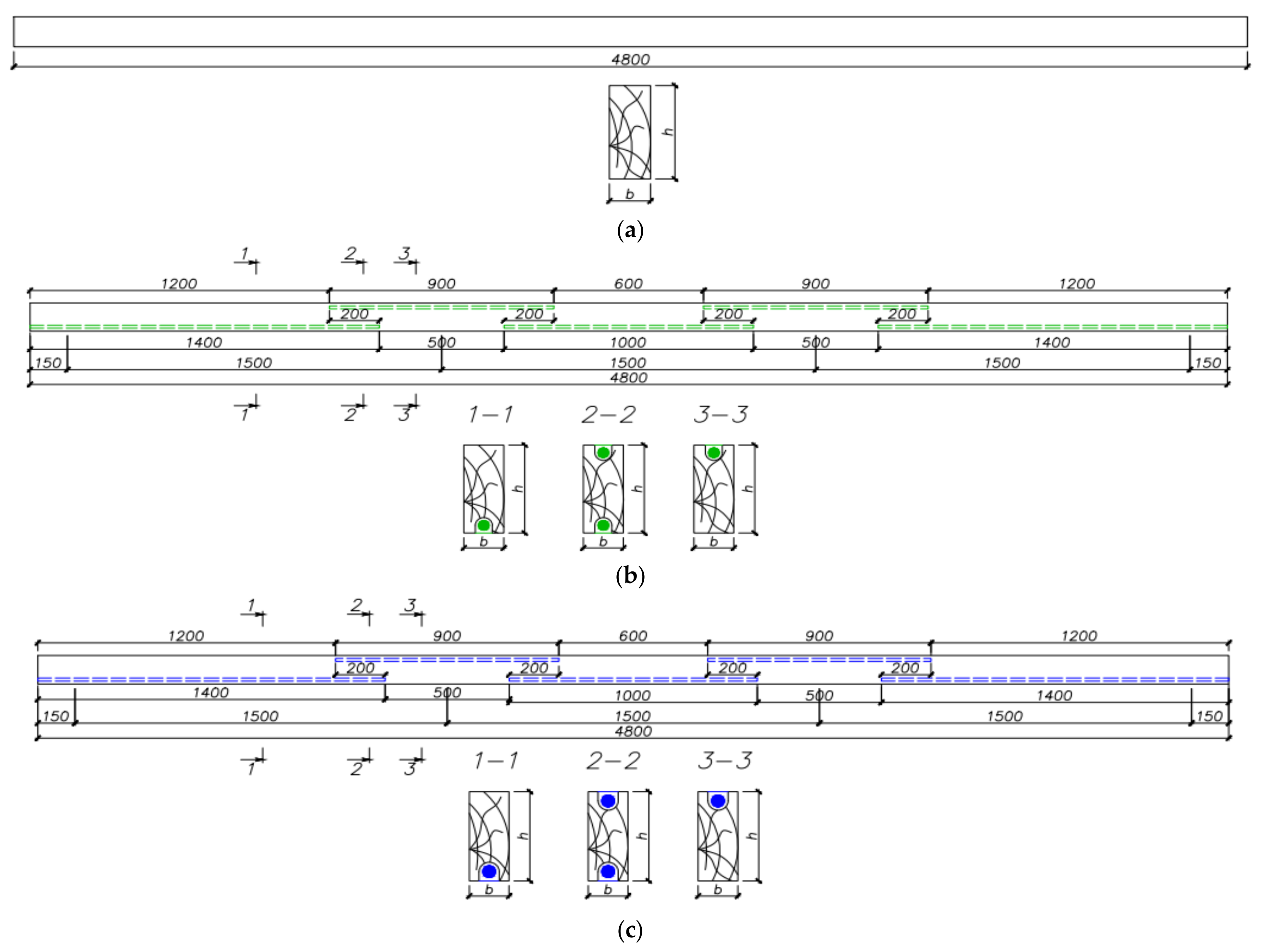
series 1—solid wood beams, taken as a standard, with 3 spans of 1.5 m each, with a section of 40 mm × 80 mm (b × h);
(2)
series 2—beams reinforced in the lower area of the span and in the upper area of the support with steel bars of A400 class, 8 mm in diameter, with 3 spans of 1.5 m each, with a section of 40 mm × 80 mm (b × h);
(3)
series 3—beams reinforced in the lower area of the span and the upper area of the support with reinforcing bars of class A400, 10 mm in diameter, with 3 spans of 1.5 m each, with a section of 40 mm × 80 mm (b × h).
The number of models in a series for testing was taken according to the formula:
n m i n = V 2   ×   t γ 2 P γ 2 ,
where V is the coefficient of variation of wood properties as a percentage, γ is the required confidence probability, and tγ is quantile of Student’s t-distribution.
The six-point loading scheme for each span was adopted for study the force-displacement state of beams with a design span of 1.5 m. With 5 or more concentrated loads, their effect on the structure can be replaced with 1 load evenly distributed over the span, which simulates the operational load with sufficient accuracy.
The experimental setup for testing beams was a stationary stand (Figure 2 and Figure 3), consisting of a reactive beam on which supports for beams and transmission shafts with a diameter of 300 mm were located. The test specimen was loaded using platforms that were attached to the transmission shafts. The load increased by 7 times through the transfer shafts and was transmitted to the beam with clamps with wooden lining. The beam′s load was transferred to the supports through metal distribution plates fixed in the support sections. These plates provided the crushing strength of the wood in the supporting areas of the structures. Additional struts rigidly connected to the reactive beam were installed for ensure the lateral beam stability.
The loading steps were assigned equal to 1/10 of the failure load. The holding time of each step was taken equal to 5–10 min. Holding was carried out after loading the structure in order to stabilize deformations at each stage of loading.
The strain gauge method using a multichannel measuring complex TDS-530 (Tokyo Sokki Kenkyujo Co., Ltd, Tokyo, Japan) and strain gauges with a base of 20 mm was chosen for experimental studies of composite three-span beams. This method provides a quantitative picture of displacements and stresses, rather than a qualitative picture. Numerical values of stresses were important to confirm theoretical studies in this work. The locations of the strain gauges on the beam are shown in Figure 3.
Vertical displacements and angles of rotation were measured by deflection meters PAO-6 (RSC Technokom, Yekaterinburg, Russia). Compression dynamometers with dial indicators with a graduation value of 0.01 mm were installed on the supports. The strains of the compressed and stretched fibers in the middle of the span were measured using Hugenberger strain gauges with a graduation of 0.001 mm and a base of 20 mm. Strain gauges were glued in the zone of action of the maximum bending moment across the section width.
The study of composite beam structures was carried out in 2 stages. At first, the integral modulus of elasticity of a wooden beam was determined, which, in contrast to the calculated modulus, took into account the heterogeneity of wood, defects, etc. The integral modulus of elasticity was not constant over time, in contrast to the calculated one, and was taken equal to the tangent of the angle of inclination to the strength curve, which was nonlinear. The integral modulus of elasticity more accurately described the actual work of structures in time. At the second stage, the force-displacement state of composite beams was investigated, and the nature of the failure was determined depending on the design parameters.
A fragment of the general view of the stand with the installed beam is shown in Figure 4.
The main tasks of experimental research include:
  • Revealing of the force-displacement state of multi-span reinforced beams and identification of the nature of the failure of such structures;
  • Determination of the magnitude of the failure loads;
  • Comparison of the results from experimental and theoretical studies.
During the research, the following individual steps can be distinguished:
  • Engineering (theoretical) calculation of beams;
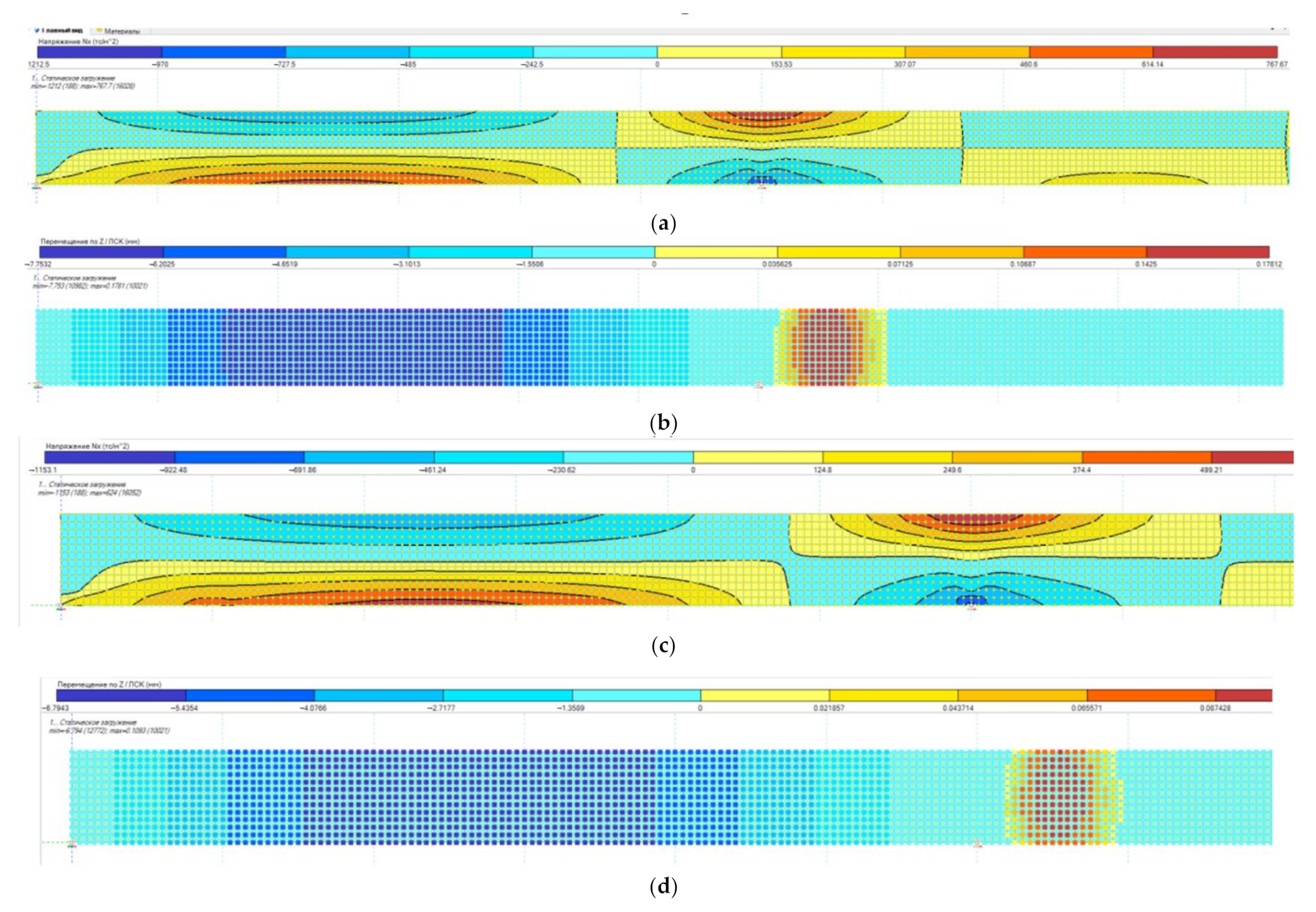
  • Numerical calculation in the software package;
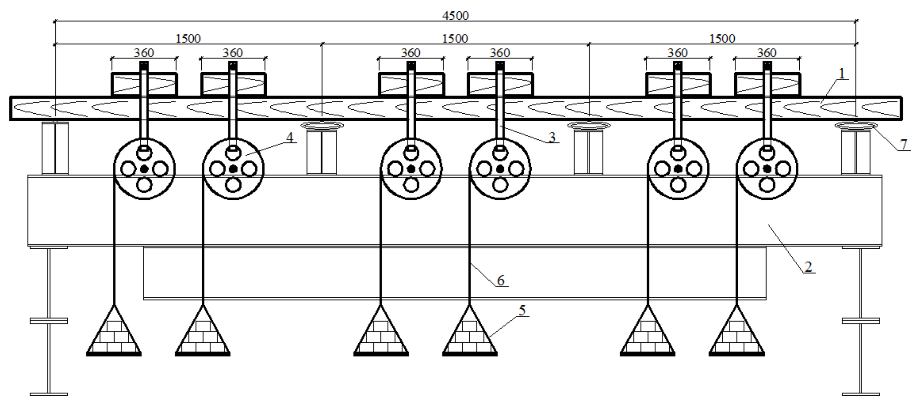
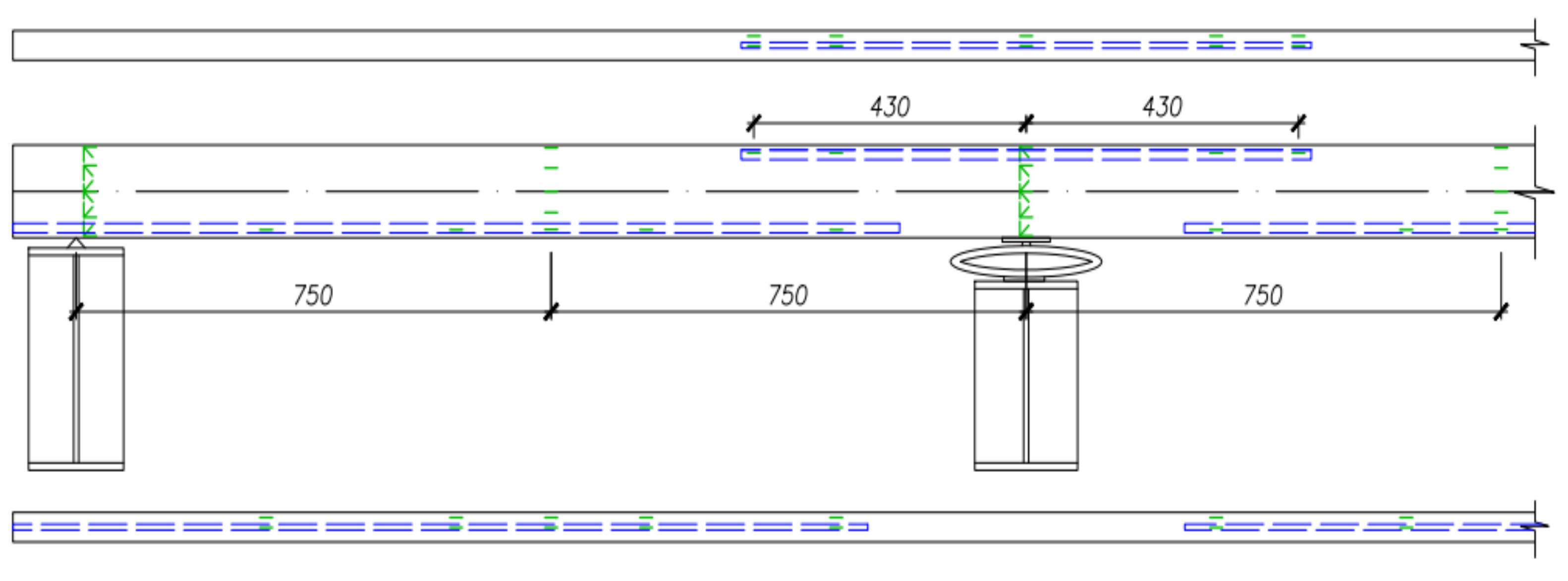
  • Planning an experimental study;
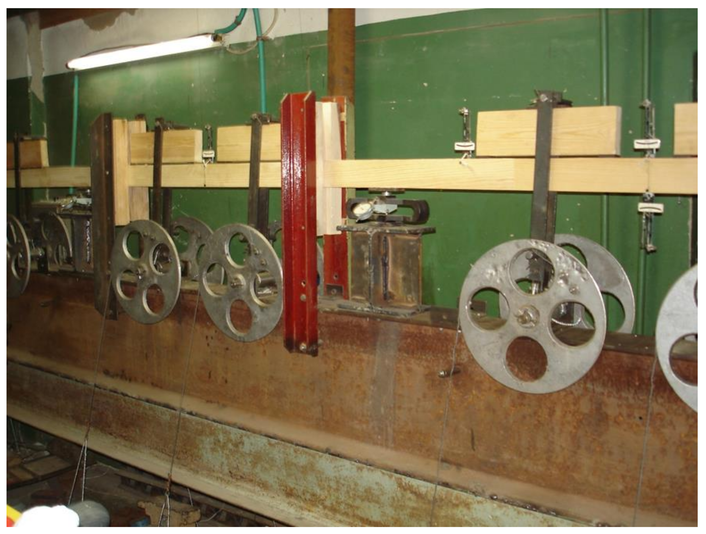
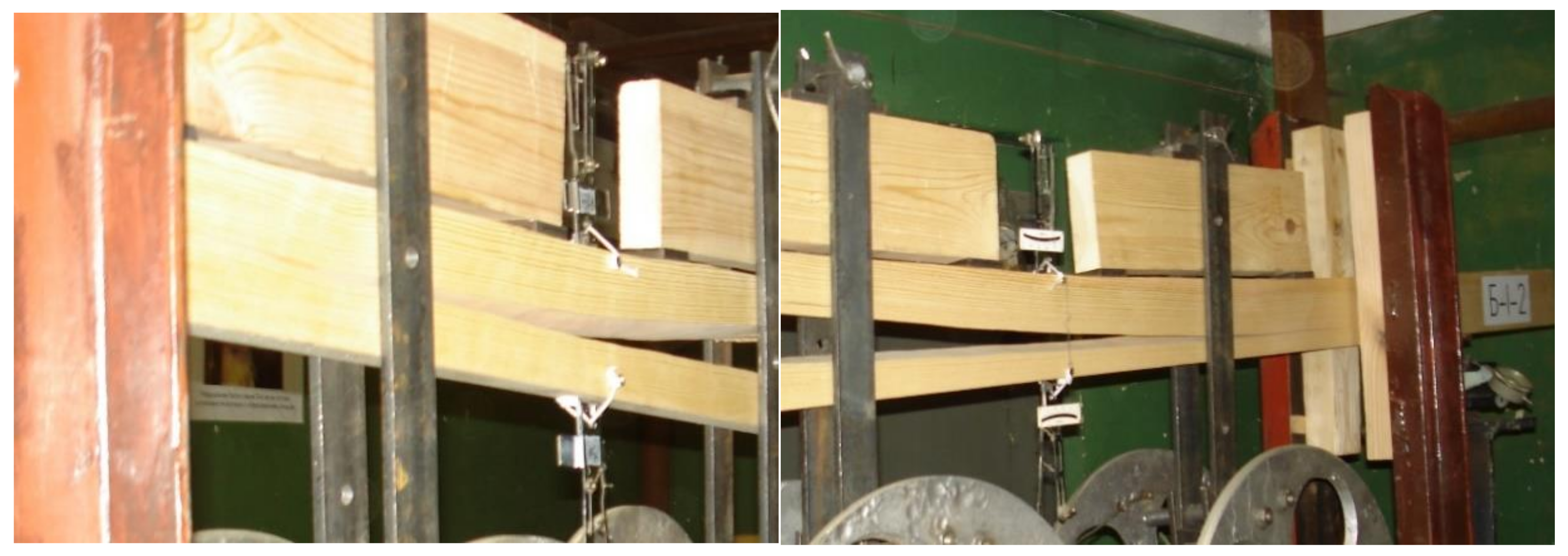
  • Experimental (laboratory) research;
  • Cameral processing of the results.
Before the manufacture of the experimental samples, a numerical calculation of the beams was performed in the Lira 10.10 software (https://lira-soft.com). The numerical calculation was carried out, taking into account all the features of the stress–strain state of the tested structures. This calculation allows for the pre-evaluation of the stress distribution in the reinforced beam, as well as the estimation of the failure load. The transtropic model of an anisotropic body was adopted in this work as a physical model of wood. To determine the elastic characteristics of the wood, we cut out standard samples of undisturbed areas of the beams after testing. Determination of the modulus of elasticity was carried out in accordance with the Russian standard 16483.24–73 “Wood. Method for determining the modulus of elasticity in compression along the fibers”. The coefficient of variation for determining the elastic modulus was assumed to be 0.15. The confidence interval for determining the elastic modulus was assumed to be 95%.
The finite element method was used for the calculations. The finite element mesh was assumed to be 10 mm in size. Finite elements for wood were lamellar, for reinforcing bars–rod. The connection of the reinforcing bars to the timber was modelled using their rigid common junctions. The diagrams of work of wood under load included in the calculation were taken from the results of testing standard specimens in tension and compression. The hypothesis of the highest normal stresses was accepted for calculations. Normal stresses were accepted due to the fact that the ultimate strength is easier to determine than the yield strength. Therefore, in determining the permissible stresses for plastic materials, one sometimes proceeds from the value of the ultimate strength.
The loading of the beams in the numerical calculation was carried out by 6 concentrated forces. The load value, at each of the 10 loading steps was assumed to be equal to 1/10 of the breaking load and amounted to 0.4 kN/m for beams of series 1 and 1.5 kN/m for beams of series 2 and 3. The calculation was performed in a non-linear formulation, taking into account the actual work of the material under load. The load–strain graphs included in the calculations were obtained by testing standard wood samples for compression and tension.
The load until stresses in wood reached the design resistance was determined from the condition of the strength of normal sections using the results of numerical studies.

3. Results and Discussion

Figure 5 shows the isofields of the stress distribution and displacements for half of the beam structure (half of the span).
The loads until stresses in wood reached the design resistance were 2.6 kN/m for wooden beams, and 6.9 and 7.9 kN/m for composite beams of series 2 and 3, respectively. The actual breaking loads identified during the experiment are presented in Table 1. The indicated values of the elastic moduli and shear moduli were used in finite element modeling.
The failure of solid wood beams began with crushing in the extreme fibers of the compressed zone with the formation of characteristic folds, and then the stretched fibers lost their stability. The failure took place in the middle of the span and was fragile. No deformations were noted in the support zones of the beams. The fractures of composite beams of series 2 and 3 were of a plastic nature, and the fracture began with a collapse in the compressed zones, after which a crack formed in the stretched zones at the location of defects in the form of a knots. Failure occurred in the span when the wood′s ultimate strength was reached. The stress in the reinforcement during testing did not exceed the design resistance and, accordingly, the yield strength. The required safety factor for the tests carried out was determined on the basis of the logarithm of the reduced time and the type of failure of structures during a short-term test. When analyzing the test, the required safety factor was k = 1.49…1.55 for series 1 of solid wood beams, and k = 1.91…2.0 for series 2 and 3 of composite beams. The safety factor was estimated as the ratio of the maximum allowable stress in wood to its design resistance. The failure of beams of a series 1 of solid wood occurred in the tensile zone in places where the section weakened due to knots or cut fibers of the near-knot cross grains with an average linear load of 4.01 kN/m. The difference between the theoretically calculated design load and the obtained experimental data was 4%. Fractures of a series 2 and 3 of composite beams occurred with the formation of plastic hinges in the form of folds in the compressed zone at an average linear load of 13.68 and 15.61 kN/m for series 2 and 3, respectively. The difference between the calculated load and the experimental one was 5%. Representative photos of the revealed characteristic fracture of structures during their failure for unreinforced beams are shown in Figure 6, and for reinforced beams in Figure 7.
The increases in strength for composite wooden beams of series 2 and 3 relative to wooden beams of series 1, provided that the requirements of the first and second groups of limit states were met, were 75% and 95%, respectively. Graphs of maximum stresses and relative deformations in the timber of beams are shown in Figure 8a,b, respectively.
Analysis of the data presented in Figure 8 shows that at the same level of loading in the tensioned and compressed zones when reinforcing wooden beams, the values of relative deformations decreased by 40 to 45%, which generally had a positive effect on the operational reliability of beams. The results obtained can be used to create new rational types of composite structures based on wood. Obviously, the durability of wooden structures with glued reinforcement increases, and also ensures their further safe operation. During the tests, the bearing capacity of series 3 beams was higher than that of series 2. The adhesive composition in the joint did not impair the performance of structures under load, since its strength was higher than that of wood, and the failure of structures in any case occurred through wood.
Figure 9 shows the curves of changes in normal stresses from deformations under tension and compression for different series of the beams.

4. Conclusions

On the basis of the performed experimental studies of multi-span reinforced beams with rational reinforcement in the places of the greatest moment action, we were able to draw conclusions and to provide the following recommendations for their use:
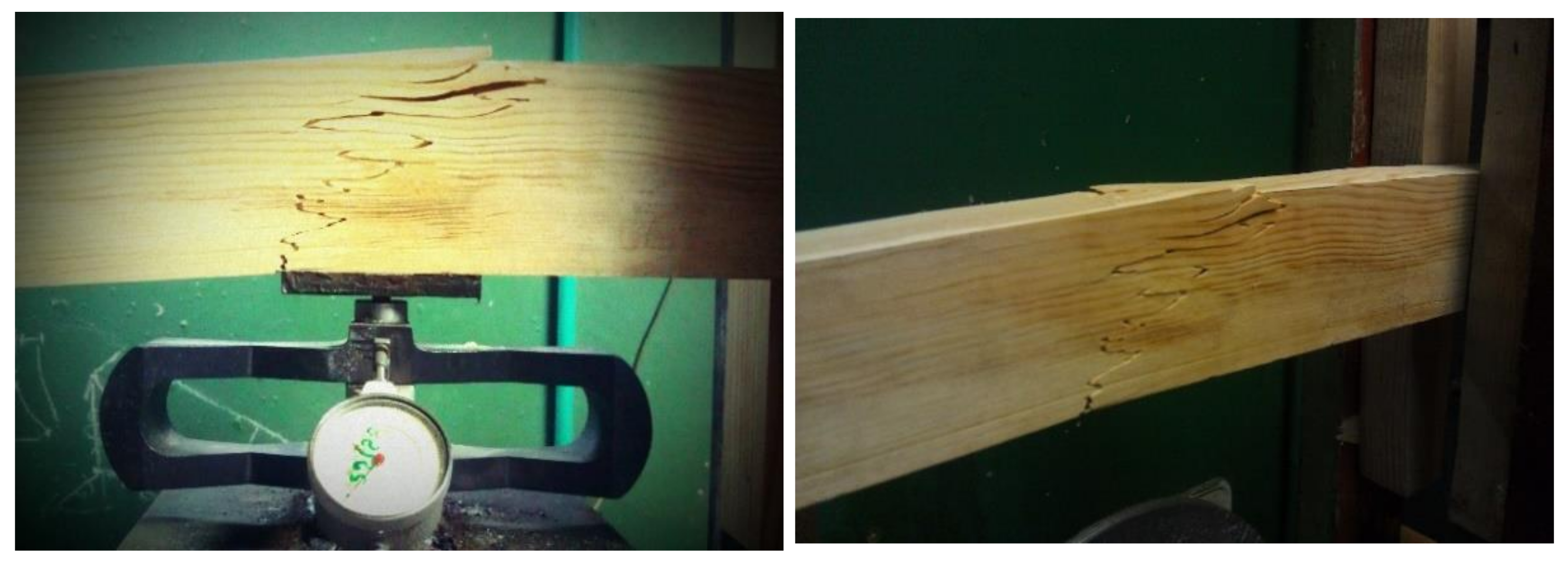
  • Fracture of a series of composite beams occurred with the formation of plastic hinges in the form of folds in the compressed zone at average linear loads of 13.68 and 15.61 kN/m for series 2 and 3, respectively. In contrast, the failure of solid wood beams occurred in the stretched zone in the places where the section weakened in the form of knots or cut fibers of the near-knot cross grains with an average linear load of 4.01 kN/m.
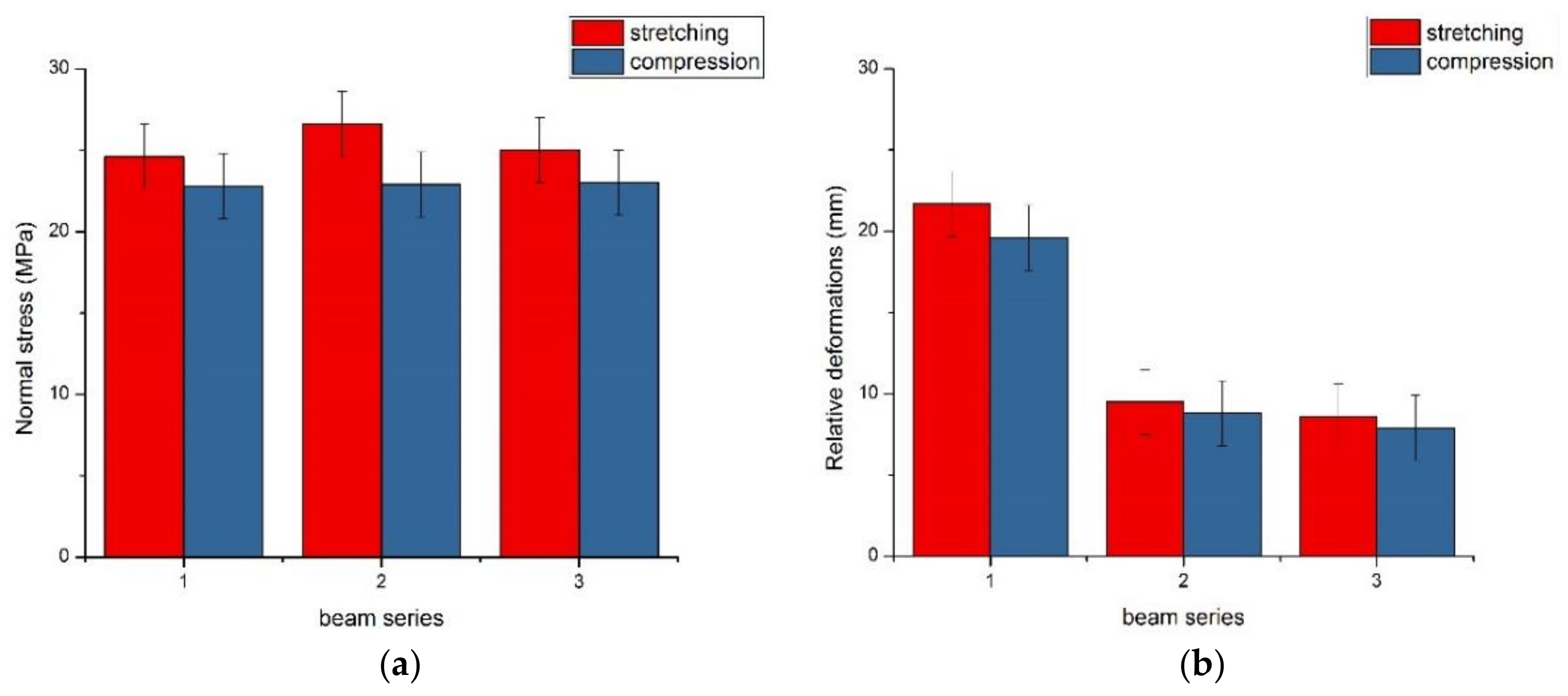
  • Rational reinforcement of wooden beams increased their bending capacity and reduces deformability by 75% and 85% for series 2 and 3, respectively. When analyzing the test, the required safety factor was k = 1.49…1.55 for a series of solid wood beams and k = 1.91…2.0 for a series of composite beams.
  • It was experimentally confirmed that the failure of composite timber beams had a plastic nature and occurred only along normal sections. These results eliminated the possibility of brittle fracture from tangential stresses and ensured the operational reliability of structures.

Author Contributions

Conceptualization, S.R. and N.V.; methodology, M.L.; software, M.L.; validation, E.P., M.L., and S.R.; formal analysis, S.R. and M.K.; investigation, M.L., E.P., and S.R.; resources, S.R.; data curation, M.L.; writing—original draft preparation, M.L.; writing—review and editing, E.P. and N.V.; visualization, E.P.; supervision, N.V.; project administration, E.P.; funding acquisition, E.P. All authors have read and agreed to the published version of the manuscript.

Funding

The research was carried out within the state assignment of Ministry of Science and Higher Education of the Russian Federation (agreement No. 075-03-2020-046/1 from 17.03.2020, theme No. FZUN-2020-0015).

Institutional Review Board Statement

Not applicable.

Informed Consent Statement

Not applicable.

Data Availability Statement

The data presented in this study are available on reasonable request from the corresponding author. The data are proprietary or confidential in nature and may only be provided with restrictions.

Conflicts of Interest

The authors declare no conflict of interest. The funders had no role in the design of the study; in the collection, analyses, or interpretation of data; in the writing of the manuscript; or in the decision to publish the results.

References

  1. Nowak, T.; Jasieńko, J.; Kotwica, E.; Krzosek, S. Strength enhancement of timber beams using steel plates—Review and experimental tests. Drewno 2016, 59, 75–90. [Google Scholar] [CrossRef]
  2. Walkup, S.L.; Erceg, M.; Brown, N.; Brown, V.L. Repair of partially embedded metal connector plates. For. Prod. J. 2016, 66, 225–232. [Google Scholar] [CrossRef]
  3. Liu, W. Research on product design method of recycling waste building wood. E3S Web Conf. 2020, 179, 01010. [Google Scholar] [CrossRef]
  4. Ribeiro, A.S.; de Jesus, A.M.P.; Lima, A.M.; Lousada, J.L.C. Study of strengthening solutions for glued-laminated wood beams of maritime pine wood. Constr. Build. Mater. 2009, 23, 2738–2745. [Google Scholar] [CrossRef]
  5. Barteneva, E.A.; Ylesin, M.A.; Mashin, N.A.; Dubrov, D.V. Improvement of heat-insulating properties of foam concrete by means of mineral additives. Key Eng. Mater. 2018, 771, 31–36. [Google Scholar] [CrossRef]
  6. Krutasov, B.V.; Ylesin, M.A.; Mashin, N.A.; Dubrov, D.V. Hydrophobic modifiers for restoration of old wooden buildings in Western Siberia. Key Eng. Mater. 2018, 771, 43–48. [Google Scholar] [CrossRef]
  7. Elesin, M.; Mashkin, N.; Bartenjeva, E.; Larichkin, V.; Nikolaeva, M. Studies of heat insulation concrete. Mater. Sci. Forum 2020, 992, 130–134. [Google Scholar] [CrossRef]
  8. Zhao, Q.Q.; Chen, M.Y.; He, R.L.; Zhang, Z.F.; Ashraf, M.A. Review on antibacterial characteristics of bridge engineering biomaterials. Saudi J. Biol. Sci. 2016, 23, S137–S141. [Google Scholar] [CrossRef] [Green Version]
  9. Roschina, S.I.; Lisyatnikov, M.S.; Melekhov, V.I.; Labudin, B.V.; Lukin, M.V. Application of high glued wooden beams in the ceiling of buildings textile plants. Izvestiya Vysshikh Uchebnykh Zavedenii Seriya Teknologiya Tekstilnoi Promyshlennosti 2016, 5, 267–271. [Google Scholar]
  10. Roshchina, S.; Lukin, M.; Lisyatnikov, M.; Koscheev, A. The phenomenon for the wood creep in the reinforced glued wooden structures. MATEC Web Conf. 2018, 245, 03020. [Google Scholar] [CrossRef]
  11. Kuzman, M.K.; Grošelj, P. Wood as a construction material: Comparison of different construction types for residential building using the analytic hierarchy process. Wood Res. 2012, 57, 591–600. [Google Scholar]
  12. Sobczak-Piastka, J.; Gomon, S.S.; Polishchuk, M.; Homon, S.; Gomon, P.; Karavan, V. Deformability of glued laminated beams with combined reinforcement. Buildings 2020, 10, 92. [Google Scholar] [CrossRef]
  13. Romano, N.; Lignola, G.P.; Brigante, M.; Bosso, L.; Chirico, G.B. Residual life and degradation assessment of wood elements used in soil bioengineering structures for slope protection. Ecol. Eng. 2016, 90, 498–509. [Google Scholar] [CrossRef]
  14. Ramage, M.H.; Burridge, H.; Busse-Wicher, M.; Fereday, G.; Reynolds, T.; Shah, D.U.; Wu, G.; Yu, L.; Fleming, P.; Densley-Tingley, D.; et al. The wood from the trees: The use of timber in construction. Renew. Sust. Energ. Rev. 2017, 68, 333–335. [Google Scholar] [CrossRef]
  15. Loss, C.; Tannert, T.; Tesfamariam, S. State-of-the-art review of displacement-based seismic design of timber buildings. Constr. Build. Mater. 2018, 191, 481–497. [Google Scholar] [CrossRef]
  16. Aseeva, R.; Serkov, B.; Sivenkov, A. Fire Behavior and Fire Protection in Timber Buildings; Springer: Berlin/Heidelberg, Germany, 2014. [Google Scholar]
  17. Luo, L.; Shi, B.; Liu, W.; Yang, H.; Ling, Z. Experimental investigation on the fire resistance of glued-in rod timber joints with heat resistant modified epoxy resin. Materials 2020, 13, 2731. [Google Scholar] [CrossRef]
  18. Ghanbari-Ghazijahani, T.; Russo, T.; Valipour, H.R. Lightweight timber I-beams reinforced by composite materials. Compos. Struct. 2020, 233, 111579. [Google Scholar] [CrossRef]
  19. Alinoori, F.; Moshiri, F.; Sharafi, P.; Samali, B. Reinforcement methods for compression perpendicular to grain in top/bottom plates of light timber frames. Constr. Build. Mater. 2020, 231, 116377. [Google Scholar] [CrossRef]
  20. Papavasileiou, G.S.; Pnevmatikos, N.G. Optimized design of steel buildings against earthquake and progressive collapse using cables. Int. J. Progress. Sci. Technol. 2017, 6, 213–220. [Google Scholar]
  21. Negrao, J.H.J.O. Preliminary study on wire prestressing methods for timber pieces reinforcement. Constr. Build. Mater. 2014, 102, 1093–1100. [Google Scholar] [CrossRef]
  22. Pnevmatikos, N.G.; Papagiannopoulos, G.A.; Papavasileiou, G.S. Fragility curves for mixed concrete/steel frames subjected to seismic excitation. Soil Dyn. Earthq. Eng. 2019, 116, 709–713. [Google Scholar] [CrossRef]
  23. Bashandy, A.A.; El-Habashi, A.E.; Dewedar, A.K. Repair and strengthening of timber cantilever beams. Wood Mater. Sci. Eng. 2018, 13, 241–253. [Google Scholar] [CrossRef]
  24. Jankowski, L.J.; Jasieńko, J.; Nowak, T.P. Experimental assessment of CFRP reinforced wooden beams by 4-point bending tests and photoelastic coating technique. Mater. Struct. 2010, 43, 141. [Google Scholar] [CrossRef]
  25. Custódio, J.; Broughton, J.; Cruz, H. A review of factors influencing the durability of structural bonded timber joints. Int. J. Adhes. Adhes. 2009, 29, 173–185. [Google Scholar] [CrossRef]
  26. Issa, C.A.; Kmeid, Z. Advanced wood engineering: Glulam beams. Constr. Build. Mater. 2005, 19, 99–106. [Google Scholar] [CrossRef]
  27. Nardone, F.; Lignola, G.P.; Prota, A.; Manfredi, G.; Nanni, A. Modeling of flexural behavior of RC beams strengthened with mechanically fastened FRP strips. Compos. Struct. 2011, 93, 1973–1985. [Google Scholar] [CrossRef]
  28. Vallée, T.; Tannert, T.; Fecht, S. Adhesively bonded connections in the context of timber engineering—A review. J. Adhes. 2017, 93, 257–287. [Google Scholar] [CrossRef]
  29. Broughton, J.G.; Hutchinson, A.R. Pull-out behaviour of steel rods bonded into timber. Mat. Struct. 2001, 34, 100. [Google Scholar] [CrossRef]
  30. Martín-Gutiérrez, E.; Estévez-Cimadevila, J.; Otero-Chans, D. Durability of joints made with threaded steel rods glued in chestnut timber—An experimental approach. Compos. Part B Eng. 2017, 108, 413–419. [Google Scholar] [CrossRef]
  31. Alam, P.; Ansell, M.; Smedley, D. Effects of reinforcement geometry on strength and stiffness in adhesively bonded steel-timber flexural beams. Buildings 2012, 2, 231–244. [Google Scholar] [CrossRef] [Green Version]
  32. Jasieńko, J.; Nowak, T.P. Solid timber beams strengthened with steel plates—Experimental studies. Constr. Build. Mater. 2014, 63, 81–88. [Google Scholar] [CrossRef]
  33. Borri, A.; Corradi, M. Strengthening of timber beams with high strength steel cords. Compos. Part B Eng. 2011, 42, 1480–1491. [Google Scholar]
  34. Koscheev, A.A.; Lukin, M.V.; Roshchina, S.I. Investigation of glued in bars strength and deformability indexes within framework of research of wood reinforcement with cable reinforcement. IOP Conf. Ser. Mater. Sci. Eng. 2019, 687, 033023. [Google Scholar] [CrossRef]
  35. De Lima, L.C.C.; Costa, A.A.; Rodrigues, C.F. On the use of prestress for structural strengthening of timber beams: Assessment with numerical support and experimental validation. Int. J. Arch. Heritage 2018, 12, 710–725. [Google Scholar] [CrossRef]
  36. De Luca, V.; Marano, C. Prestressed glulam timbers reinforced with steel bars. Constr. Build. Mater. 2012, 30, 206–217. [Google Scholar] [CrossRef]
  37. Miebach, F. Design ideas for solid timber bridges. Wood Mater. Sci. Eng. 2018, 13, 184–189. [Google Scholar] [CrossRef]
  38. Corradi, M.; Osofero, A.I.; Borri, A. Repair and reinforcement of historic timber structures with stainless steel—A review. Metals 2019, 9, 106. [Google Scholar] [CrossRef] [Green Version]
  39. Wu, W.; Gou, H. Analyzing of the timber beams of ancient buildings strengthened with NSM stainless steel bars. Int. J. Sci. 2015, 2, 77–87. [Google Scholar]
  40. Metelli, G.; Preti, M.; Giuriani, E. On the delamination phenomenon in the repair of timber beams with steel plates. Constr. Build. Mater. 2016, 102, 1018–1028. [Google Scholar]
  41. Ghanbari-Ghazijahani, T.; Jiao, H.; Holloway, D. Composite timber beams strengthened by steel and CFRP. J. Compos. Constr. 2017, 21, 04016059. [Google Scholar] [CrossRef]
  42. Li, A.; Zhou, K.; Wang, C.; Xie, L. Prospective analyses on restoration and reinforcement techniques toward wooden structure of Chinese ancient architectures. J. Southeast Univ. Nat. Sci. Ed. 2019, 49, 195–206. [Google Scholar] [CrossRef]
  43. Al Ali, M.; Bajzecerova, V.; Kvocak, V. Design methods of timber-concrete composite ceiling structure. Mag. Civ. Eng. 2017, 5, 112. [Google Scholar] [CrossRef]
Figure 1. Variants of the investigated multi-span reinforced beam structures: (a) series 1—solid wood beam; (b) series 2—composite beam, reinforcement coefficient 0.016; (c) series 3—composite beam, reinforcement coefficient 0.025. Values are expressed in mm.
Buildings 11 00046 g001
Figure 2. Experimental stand: 1—mounted beam; 2—reactive beam; 3—clamps with wooden lining; 4—transfer shaft-coil; 5—baskets with cargo; 6—cables; 7—dynamometers. Values are expressed in mm.
Buildings 11 00046 g002
Figure 3. The locations of the strain gauges on the beam. Values are expressed in mm.
Buildings 11 00046 g003
Figure 4. Experimental stand with mounted beam.
Buildings 11 00046 g004
Figure 5. The isofields of the distribution of stresses and displacements for the half of the beam: (a) isofields of normal stresses σx, MPa for a glued beam (half-length); (b) vertical displacements z, mm for a glued beam (half-length); (c) isofields of normal stresses σx, MPa for a composite beam (half-length); (d) vertical displacements z, mm for composite beam (half-length).
Buildings 11 00046 g005
Figure 6. Characteristic fracture of unreinforced beams during their failure.
Buildings 11 00046 g006
Figure 7. Characteristic fracture of reinforced beams during their failure.
Buildings 11 00046 g007
Figure 8. Maximum normal stresses (a) and relative deformations (b) in the wood beams of various types: 1—solid wood beam; 2—composite beam with a reinforcement coefficient of 0.016; 3—composite beam with a reinforcement coefficient of 0.025.
Buildings 11 00046 g008
Figure 9. Stress–deformation relationships under compression (a) and tension (b) for the beams of different series.
Buildings 11 00046 g009
Table 1. Beam experimental test results.
Beam SeriesSectionDesign Load p, kN/mDeformations, ε × 10−4Failure Load, kN/mSafety FactorModulus of Elasticity, MPaShear Modulus, MPa
h, mmb, mmTimber
CompressedStretched
1/179.040.02.619.4221.704.101.5713,255576.3
1/280.039.0−”−19.4821.703.891.4912,868559.5
1/380.039.5−”−19.5221.684.051.5512,735553.7
2/181.040.06.98.879.5213.852.0012,237532.0
2/281.039.0−”−8.899.5513.962.0213,035566.7
2/379.040.0−”−8.859.4913.241.9112,438540.8
3/180.041.07.97.798.5415.641.9712,774555.4
3/279.039.0−”−7.908.5915.321.9312,894560.6
3/380.040.0−”−7.878.6515.872.0013,002565.3
Publisher’s Note: MDPI stays neutral with regard to jurisdictional claims in published maps and institutional affiliations.

