Article

Evaluation of Non-Autoclaved Aerated Concrete for Energy Behaviors of a Residential House in Nur-Sultan, Kazakhstan

Department of Civil and Environmental Engineering, School of Engineering and Digital Sciences, Nazarbayev University, Nur-Sultan 020000, Kazakhstan
*
Author to whom correspondence should be addressed.
Buildings 2021, 11(12), 610; https://doi.org/10.3390/buildings11120610
Submission received: 11 November 2021 / Revised: 23 November 2021 / Accepted: 25 November 2021 / Published: 4 December 2021

Abstract

:
Autoclaved aerated concrete (AAC) is commonly used as a modern, energy-efficient construction material in Nur-Sultan, Kazakhstan—the second-coldest national capital in the world after Ulaanbaatar, Mongolia. The autoclave curing method used to manufacture the AAC has potential risks and is environmentally costly because of its high-pressure and -temperature operation. Therefore, for phase I and II studies, non-autoclaved aerated concrete (NAAC) was cast, and its properties were evaluated in terms of compressive strength, density, porosity, and thermal conductivity. Moreover, the thermal conductivity prediction model of NAAC was successfully developed. In this Phase III study, the energy behavior of the NAAC was evaluated by energy simulation for a typical two-story residential house model in Kazakhstan. Different wall materials, such as fired brick and normal concrete, were adapted to compare the energy performance of NAAC. Finally, the annual heat loss and amount of heat transferred through the wall of the house were calculated to cross-check the energy-saving effect of NAAC. It was found that the NAAC conserved energy, because the heating and cooling loads, annual heat loss, and amount of heat transfer of NACC were lower than those of fired brick and normal concrete.

1. Introduction

In the past decade, sustainable or green building technology in the construction industry has been adapted and has grown continuously. Green building is defined as the practice of creating structures and using environmentally responsible and resource-efficient processes throughout a building’s life cycle, from the planning stage to the demolition of the building. This practice includes not only the classical building design criteria such as economy, utility, durability, and comfort, but also the efficient use of land, water, resources, and energy in and around the building, with a low environmental impact [1,2,3].
The demand for constructing energy-efficient residential houses and buildings is gradually rising, especially in Nur-Sultan, the capital city of Kazakhstan. Nur-Sultan has a significant temperature difference between seasons, with long, harsh winters and short, hot summers. While summer temperatures occasionally reach +35 °C, the temperature between mid-December and early March usually ranges from −20 to −35 °C, along with an average wind velocity of 5.2 m/s, reaching as high as 31 m/s [1,4]. Because of such severe weather conditions, heating and cooling costs of residential houses and buildings form the bulk of operating expenses in the residential houses and buildings in Nur-Sultan. For example, more than 30% of total energy is consumed by residential buildings, and the heat energy consumption in Nur-Sultan increased from 4963 MW to 6401 MW between 2010 and 2014 [5,6]. Moreover, up to 35% of heat loss is induced through the walls in the existing conventional houses built in the 1990s. Therefore, designing an energy-efficient building with the proper construction materials can significantly save homeowners in terms of energy-related operations and maintenance costs.
Aerated concrete (AC) is a modern energy-efficient construction material classified as lightweight concrete due to its low density and strength [7]. According to the production method, the AC can be divided into cellular concrete (CC) and autoclaved aerated concrete (AAC). CC is produced using an organic or synthetic foaming agent and a normal curing method. In contrast, AAC is manufactured using an expansion agent such as aluminum (Al) powder and an autoclaved curing process [8,9]. As a building material, AAC is typically used in concrete masonry units, such as blocks. The typical mixture composition of AAC includes binders (cement and lime), silica-rich supplementary cementitious material, fine aggregates (silica and quartz mineral aggregates), an expansion agent (Al), and water [10,11]. The unique property of AAC is its low thermal conductivity coefficient. The λ of AAC is attributed to the millions of evenly distributed, uniformly sized, and entrapped air voids caused by the chemical reaction between Al powder and alkalis in the cementitious mixtures, producing hydrogen gas [12,13]. Despite depending on the mixture proportions, the typical porosity of AC ranges from 75 to 90% [14]. This unique property gives AAC a thermal conductivity (λ) as low as 0.085–0.30 W/(m·K), depending on density, curing method, moisture content, mixture proportions, and ingredients [13,15]. For example, Walczak et al. [13] reported that the λ value of sand-based AAC is approximately 0.15 W/(m·K), while the λ value of fly-ash-based AAC is 0.085 W/(m·K) at the same density (400 kg/m3).
For energy conservation, Walczak et al. [13] reported that the λ value of materials used for the construction of buildings should be lower than 0.23 W/(m·K) in order to reduce energy consumption and utility bills; AAC can fulfill this condition. Several researchers have studied the energy efficiency quality of AC materials. Radhi [16] reported that the use of AC materials in the wall layer of buildings reduced energy use by 7%. Narayanan and Ramamurthy [7] described how AAC provides better thermal insulation than conventional concrete blocks, and is considered to be an energy-efficient material, conserving temperature and reducing energy consumption. From the viewpoint of sustainability, approximately 350 kg of CO2 emissions could be saved by each 1 m2 of AAC wall throughout the life cycle of a building [17]. According to the research survey conducted by the Portland Cement Association (PCA), 77% of design professionals assert that AAC can be considered a sustainable material that corresponds to all sustainability requirements [18].
Several researchers have compared different building materials, including AAC, in terms of energy consumption. For example, Kaşka and Yumrutaş [19] examined various multilayer building walls consisting of materials commonly used in Turkey, which include briquettes, bricks, blokbims, and AAC. They found that AAC is a more suitable wall material than the other materials because it has a lower temperature at the inner surface, and heat flows through the wall when the external air temperature is high. Heathcote [20] determined the internal temperature of a building without an air conditioner during the summer days, which was constructed with brick veneer, mud bricks, and AAC wall panels; his results indicated that the internal temperature of the building constructed with AAC was 25.0 °C, while the those constructed with brick veneer and mud bricks were 25.4 °C and 26.6 °C, respectively; he concluded that using walls with AAC leads to a more comfortable room than the other materials. Aybek [18] also conducted building energy simulations with AAC, wooden frames, and metal frames; he found that the building model made with AAC consumed 14% and 11.6% less energy than the wood-framed and metal-framed models, respectively.
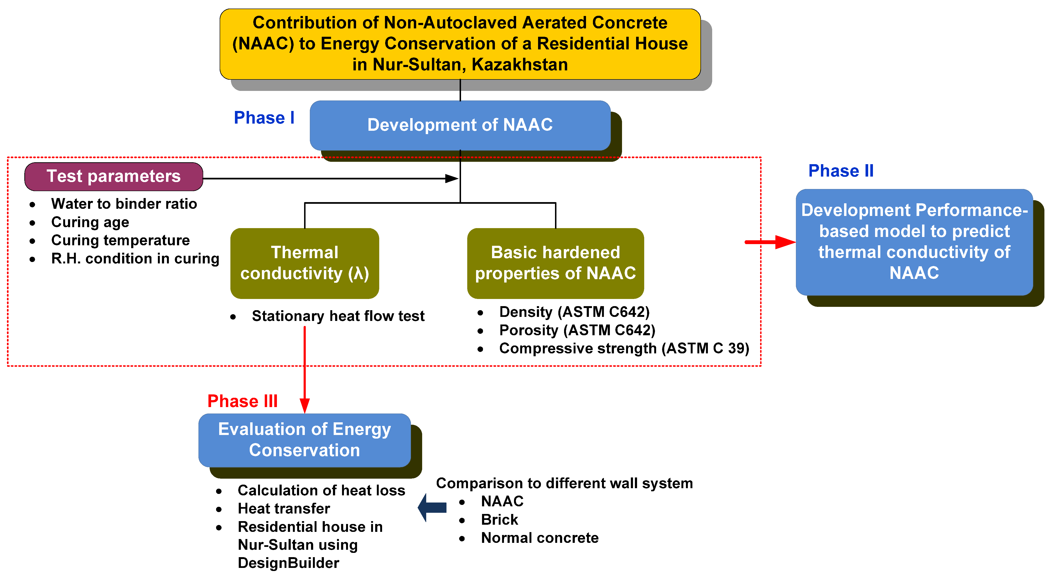
As previously stated, AC produced using an expansion agent, such as Al powder, typically uses an autoclaved curing method. The autoclave curing used for the AC has potential risks and is environmentally costly because of its high-pressure and -temperature operation. Therefore, a non-autoclaved aerated concrete (NAAC) cured in the air, or in a moist room at 100% RH, was developed. The authors’ previous work successfully assessed the properties of NAAC in terms of compressive strength, porosity, and λ, and found that NAAC could have enough strength and a similar λ to AAC [
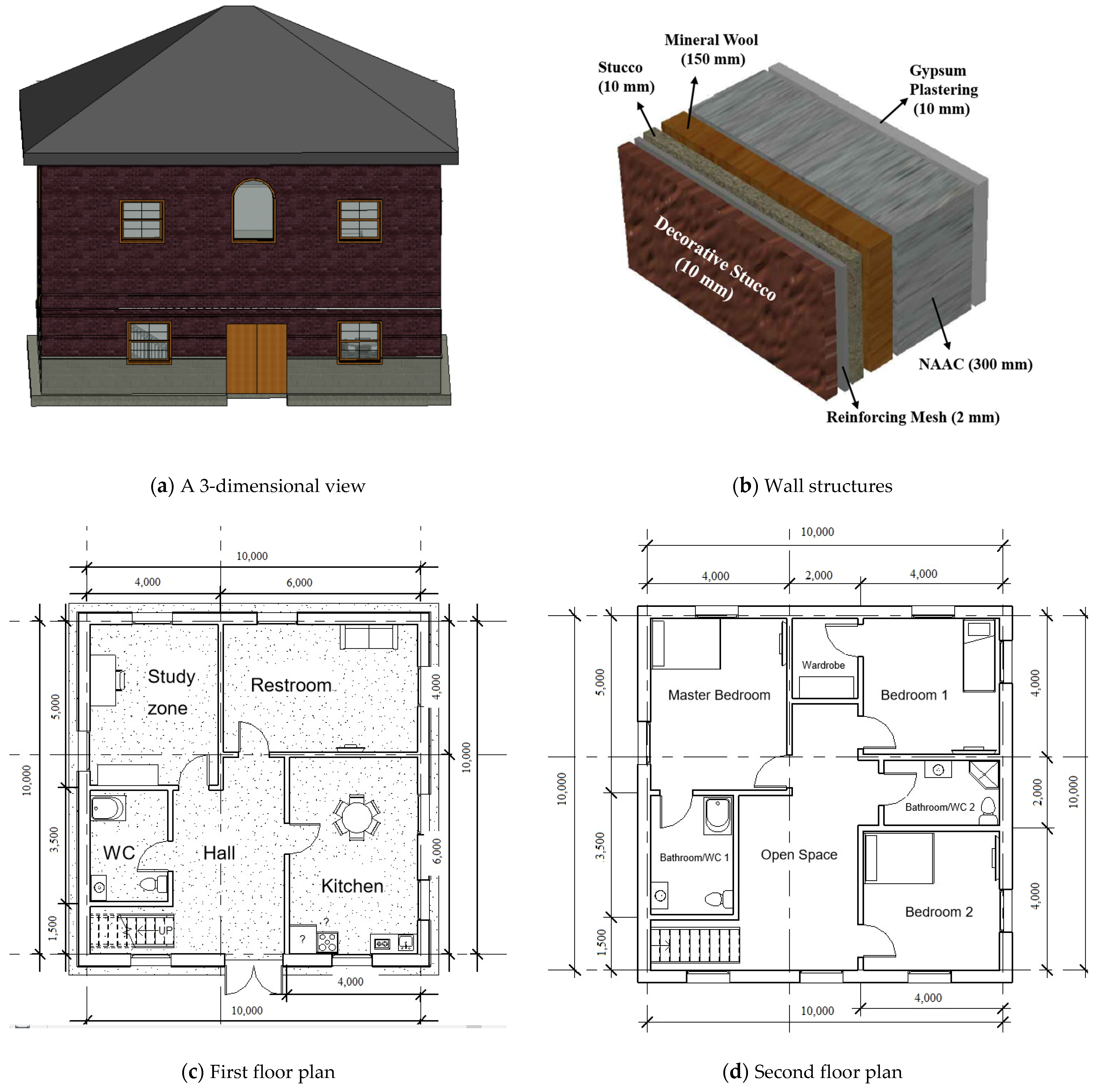
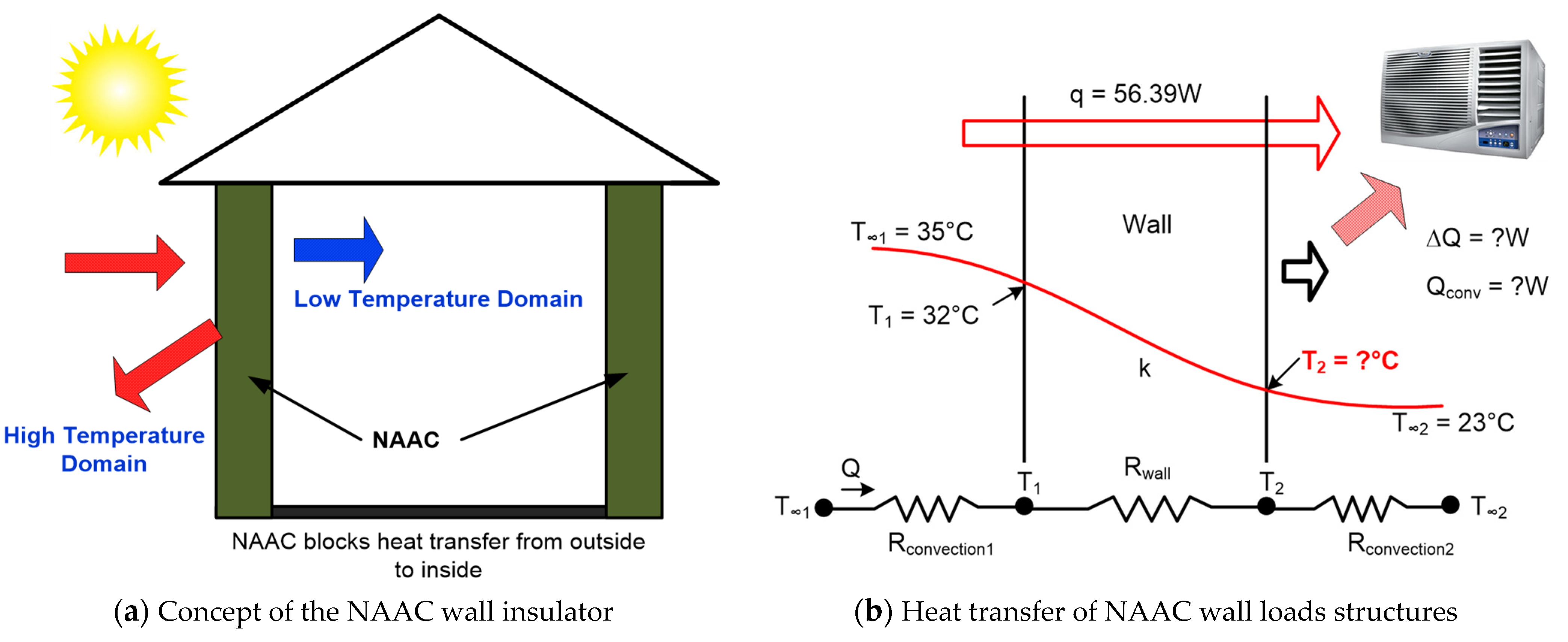
10]. However, when NAAC is used as a building wall material in a residential house in Nur-Sultan, Kazakhstan, it is interesting how much the NAAC contributes to energy conservation. Therefore, in this research, the energy-saving potential of NAAC to improve the energy performance of a residential house was assessed throughout the simulation with DesignBuilder software tools. Finally, both simple annual heat loss and heat transfer through the walls of the building were calculated.

2. Research Scope and Summary of Phases I and II Work

2.1. Research Scope

This research aims to evaluate how much NAAC contributes to the energy conservation of a residential house in Nur-Sultan, Kazakhstan. As presented in Figure 1, this goal was accomplished by three principal works: (1) the manufacture of NAAC, (2) the development of a performance-based model to predict the thermal conductivity of NAAC, and (3) evaluation of the energy conservation of a residential house containing NAAC walls.
In phases I and II studies, manufacturing of NAAC and development of a prediction model of NAAC’s thermal conductivity were successfully conducted and reported [9,20]. The mix design formulation(s) was accomplished by determining density, porosity, compressive strength, and λ under various curing conditions and different water-to-binder ratios (w/b). Furthermore, based on the linear relationship between λ and test parameters and the normalized curves for each parameter, the performance-based mathematical model to predict the λ of NAAC was developed. The advantage of this modeling is that it considers all mixture design parameters and curing conditions. However, there is room to improve the performance-based model to predict the λ of NACC. For example, taking the moisture content of the NAAC mixture as an input parameter for the prediction model may increase the model’s reliability.
As a phase III work, this paper mainly focuses on evaluating the contribution of NAAC to energy conservation. The obtained λ values of NAAC mixtures from phase I and II studies were used to calculate the heat loss and transfer for a typical residential house with NAAC walls. Finally, the energy-saving potential of building walls consisting of NAAC was compared to that of the brick and regular concrete commonly used in Kazakhstan throughout the simulation, using DesignBuilder software (V7, DesignBuilder Software Ltd., Stroud, UK).

2.2. Summary of Phase I and II Work

2.2.1. Mixture Proportions and Levels of Test Parameters

Nine NAAC mixtures were cast to evaluate key parameters influencing the λ of NAAC in the phase I study. Test parameters included the w/b, curing age, curing temperature, and moisture condition of the cured specimen. Compressive strength, porosity, density, and λ value of NAAC were obtained from the tests. The NAAC was produced with 42.0% sand, 12.9% cement, 9.0% lime, 0.06% aluminum powder, and 36.04% water. Mixture proportions and levels of test parameters are presented in Table 1 and Table 2, respectively.

2.2.2. Materials and Test Methods

Ordinary Portland cement (OPC-ASTM Type I), lime, three types of sand with different Al2O3 and SiO2 contents, and aluminum (Al) powder were used to cast NAAC. The Al2O3 and SiO2 contents were equal to 11.27% and 56.54%, respectively, in Sand 1; 0.64% and 78.83%, respectively, in Sand 2; and 16.57% and 72.92%, respectively, in Sand 3. Al powder with a medium size of 44–53.5 µm was used as an expansion agent, producing the volume-increased portion of the concrete as a result of many hydrogen–air holes caused by a chemical reaction between the water, Al powder, and alkalis released from cementitious materials (binders). The OPC with specific gravity of 3.14 had the following chemical composition: 18.20% SiO2, 4.01% Al2O3, 11.79% Fe2O3, 53.8% CaO, 0.79% K2O, 0.16% Na2O, 0.58% MgO, 0.20% TiO2, 0.46% MnO, and 4.32% SO3.
Cubic specimens with dimensions of 50 mm × 50 mm × 50 mm were cast for the compressive strength tests, while prismatic-shaped samples with dimensions of 150 mm × 150 mm × 30 mm were cast for the thermal conductivity measurements. During the casting process for the thermal conductivity samples, the concrete mixture was placed into a mold with two layers, and 25 strokes of the tamping rod per layer were applied by a metal rod. Surplus concrete from the mold was removed, and then the mold containing concrete was put into an oven maintained at 40 °C and 40 ± 5% relative humidity (RH), and then covered with plastic sheets for 2 h. After 24 h oven curing, the NAAC specimens were demolded and placed under various curing conditions, as described in Table 2. Three samples per mixture were made in order to increase the reliability of the test results.
The λ of NAAC was measured using a thermal conductivity measuring equipment based on stationary heat flow. This device can measure three thermal properties—thermal conductivity (W/mK), thermal insulance (m2∙K/W), and heat flux (W/m2)—using the specimen, which had dimensions of 150 mm × 150 mm and thickness ranging from 3 mm to 40 mm.
Based on the ASTM C642-13 Standard Test Method for Density, Absorption, and Voids in Hardened Concrete, the density and porosity of the NAAC sample were determined.

2.2.3. Test Results

Figure 2 presents the development of compressive strength over time for each mixture. Regardless of mixture type, the compressive strength increased as curing age increased. Moreover, the comparison of strength development in mixtures 7–9 clearly shows that the increase in w/b led to lower compressive strength.
In moist curing, the compressive strength generally increased as the curing temperature increased. Interestingly, the compressive strength decreased as the curing temperature increased for the mixtures cured in dry conditions. This result was due to the loss of water from the drying surface of the concrete, which did not contain enough water for further continuation of the hydration process.
Figure 3 shows the relationship between the λ and porosity-to-density ratio (P/D) of NAAC mixtures at 14 and 28 days. In general, the concrete mixtures with higher porosity and lower density have a low λ value, regardless of curing age; in other words, the higher the P/D, the lower the λ [1].
As expected, the λ values of the NAAC mixture increased as the P/D increased, except for the moist-cured (saturated) specimens. For example, the λ value of mixture 9, with a P/D of 0.055, was 0.233, while the λ value of mixture 7, with a P/D of 0.039, was 0.426; 28-day-cured specimens followed the same trend. Interestingly, the moist-cured sample followed the opposite trend: the higher the P/D, the higher the λ. This result may be attributed to the curing temperature, which affects the formation of large and open-connected pores in the NAAC. Machrafi and Lebon [21] reported that the λ was considerably increased when pore size increased from nano- to macro-pores. Bhattacharjee and Krishnamoorthy [22] reported that concrete with open-pore cells had higher λ than that with enclosed pores, because open-cell concrete has more chance of being saturated. It should be noted that a higher curing temperature at an early age produces coarse and open-cell pores that are filled with free water, consequently resulting in larger λ values.
Phase I research has also investigated how different parameters—such as the w/b, curing age, curing temperature, and moisture condition of the cured specimen—influence the λ of the NAAC mixture. In summary, the λ of the NAAC mixture decreased with the increase in w/b, curing age, and air-dried curing temperature, whereas the λ increased with the rise in the curing temperature under saturated conditions. For example, Figure 4 presents the effect of w/b on the λ of NAAC specimens cured for 14 and 28 days. As previously stated, the λ of the NAAC mixture decreased as the w/b increased. This result can be attributed to the fact that higher water content increases the intensity of pore formation, which creates more pores in the NAAC and, eventually, leads to a lower value of λ.
Based on the phase I study results, a performance-based model to predict the λ of NAAC mixture was successfully developed (phase II work). The model showed good reliability to predict 28-day λ of NAAC mixtures, along with an R2 value of 0.875 [10]. This model was based on the relationship between λ and each test parameter, as described above and in Table 2.

3. Evaluation of Energy Behavior in a Residential House (Phase III Study)

3.1. Building Characteristics, Material Properties, and Simulation Software

To determine the contribution of NAAC to the energy conservation of a residential house in Nur-Sultan, Kazakhstan, the geometry of the house was first established. As presented in Figure 5a,c,d, a typical two-story conventional house with a total area of 191.5 m2 was used as the simulation model. The first floor of the house consisted of a hall, kitchen/dining room, bathroom, guest room, and family room, with areas of 19 m2, 24 m2, 8.75 m2, 20 m2, and 24 m2, respectively. The second floor comprised a hall, master bedroom (including a bathroom), 2 bedrooms, and 2 bathrooms, with areas of 16 m2, 20 m2, 36 m2, and 16.1 m2, respectively. House geometry components for the simulation are given in Table 3.
Materials for six wall layers consisted of 10 mm decorative Munich stucco, 2 mm reinforcing mesh, 10 mm stucco, 150 mm mineral wool, 300 mm NAAC, and 10 mm gypsum plastering, as shown in Figure 5b. As previously stated, the other two sets of wall structures, with brick and normal concrete—the most common materials for constructing conventional houses in Kazakhstan—instead of NAAC, were also selected in order to evaluate the differences in energy-saving performance between different materials. The properties of each material in the wall structure—such as density, specific heat, and thermal conductivity—are given in Table 4.
The software simulation used these geometric models and material properties to evaluate how much energy could be saved for the residential house with different materials. While the DesignBuilder software with a cross-platform use of EnergyPlus (V9, U.S. Department of Energy, Washington DC, USA) as the main simulation engine was used for whole-house energy simulation, the Autodesk Revit software (Revit 2021, Autodesk, San Rafael, CA, USA) was used to quickly create the geometry and floor plans needed for simulating the house.

3.2. Calculation of Annual Heat Loss

To cross-check the energy-saving effect of NAAC, the annual heat loss (AHL) through the wall of the house was calculated using the American Society of Heating, Refrigerating, and Air-Conditioning Engineers (ASHRAE) method [23], considering the same house geometry mentioned above. In the ASHRAE method, it is necessary to know the terminology of heating degree days (HDD), cooling degree days (CDD), and degree days. Whereas HDD is the amount of energy that is required to heat the building during the cold season, CDD is the amount of air conditioning required during the hot season. The degree day is the index of fuel consumption demonstrating how many °F the mean temperature fell below 65 °F for the day. Because Nur-Sultan is located in the seventh climate zone, with 9000 < HDD65 °F ≤ 12,600, the annual HDD65 value of 10,291 was used. In order to calculate the AHL, this value was multiplied by the heat loss per degree day (HLPDD), which is the heat loss per day with one degree between the internal and external temperatures. The HLPDD can be obtained from Equation (1):
H L P D D = A × ( T i n s i d e T o u t s i d e ) R × 24 h day
where HPLDD = heat loss per degree day; A = total wall area (ft2); ( T i n s i d e T o u t s i d e ) = 1 °F; and R = thermal resistance (h·ft2·F/Btu).
Thermal resistance was calculated using Equation (2):
R = Δ x λ
where Δ x = the thickness of the wall layer (ft); and λ = thermal conductivity (Btu·in/h·ft2·F).

3.3. Estimation of Heat Transfer

To further validate the effect of NAAC on energy saving, heat transfer through the wall of the house was estimated based on a one-dimensional heat transfer method developed by Thomas [24]. Figure 6 shows a steady-state one-dimensional heat transfer model; it is assumed that the wall is a homogeneous material with constant thickness and constant thermal conductivity, and that each face of the wall is held at a continuous uniform temperature. The wall heat transfer system consists of two convection elements on the outside and inside of the wall, and one heat conduction element inside the wall.
In general, the one-dimensional heat transfer model uses the following concept: rate of heat convection into the wall = rate of heat conduction through the wall = rate of heat convection from the wall. Table 5 presents the elements used to calculate the heat transfer through the wall, including the air conditioner and inner surface temperature. Therefore, the heat transfer of the wall was calculated using Equation (3).
Q w = h 1 × A × ( T 1 T 1 ) = λ × A × ( T 1 T 2 ) Δ x = h 2 × A × ( T 2 T 2 )
where Q w = heat transfer of wall; A = area of the wall (m2); T 1 = outdoor temperature; T 1 = outer wall surface temperature; T 2 = inner wall surface temperature; T 2 = indoor temperature; λ = thermal conductivity (W/(m·K)); Δ x = wall thickness (m); h = heat transfer coefficient (W/m2·K).

4. Results and Discussion

4.1. Evaluation of Energy Conservation from DesignBuilder Simulation

4.1.1. Energy Consumption of 9 NAAC Mixtures

Figure 7 shows the simulation results of monthly heating and cooling loads for nine different NAAC mixtures. It was observed that NAAC mixture 3, with the lowest λ value, had a significant reduction in heating and cooling loads for each month. For example, the heating and cooling loads in January and July for mixture 3 were 5346 kWh and 2253 kWh, respectively, when these months recorded the lowest and highest outdoor temperatures of the year, respectively. These values were 1.6% and 6.3% lower than the heating and cooling loads in the same months, respectively, for mixture 6, which had the highest λ value. Therefore, it can be concluded that NAAC with a lower λ value leads to lower heating and cooling energy needs, depending on the mixture parameters used in the NAAC mixture.
In the meantime, Table 6 indicates the energy consumption for heating and cooling of the individual rooms when mixture 3, with the lowest λ value, was used. The annual total energy consumption of heating and cooling for both the first and second floors was 22,515.2 kWh and 6760.8 kWh, respectively. The kitchen, dining room, and hall space recorded the maximum heating (1204.5 kWh) and cooling (445.7 kWh) consumption because of its having the largest area (43 m3). This area also had the most significant 12-month average heating and cooling energy consumption, with 419.0 kWh and 109.5 kWh, respectively.

4.1.2. Energy Consumption of Three Different Wall Materials

The monthly heating and cooling loads for NAAC (mixture 3), brick, and normal concrete are shown in Figure 8. The heating and cooling loads of NAAC were lower than those of brick and normal concrete for the entire year. For example, the heating load of NAAC in January was 5346 kWh, while the heating loads of brick and normal concrete were 5421 kWh and 5445 kWh, respectively. This result indicates that the use of NAAC in wall structure layers leads to a 1.4% and 1.8% reduction in heating load in January compared to brick and normal concrete, respectively. However, the heating load from May to August presents almost zero reading because of higher seasonal temperature, regardless of wall materials.
On the other hand, the maximum cooling load—irrespective of the type of wall material—was recorded in July, which has the highest outdoor temperature. In July, the energy consumption for cooling with NAAC was 2253 kWh, whereas brick and normal concrete had energy demands for cooling of 2379 kWh and 2381 kWh, respectively. Again, this result indicates that the NAAC reduces the cooling load by 5.3% and 5.4% compared to brick and normal concrete, respectively. Therefore, these results clearly indicate that the NAAC has higher energy conservation than brick and normal concrete.

4.1.3. Analyses of Cost, Site Energy, and Source Energy

Table 7 compares the cost, site energy, and source energy between three different wall materials. The site energy is the energy consumed at the final destination of the power generation cycle to maintain the desired conditions; in other words, it is all of the energy consumed by the house (building), and is typically expressed in utility bills. The source energy contains site energy as well as all energies that are produced; this includes the raw materials (e.g., coal) that are consumed to create the power that is distributed to consumers, as well as the power (e.g., electricity) that enters the distribution system [25].
Both site energy and source energy of two-story houses using NAAC are lower than those of brick and normal concrete materials. In fact, a building made with NAAC, which has lower a material cost than brick or normal concrete, leads to 1.08% and 1.38% lower source energy savings than similar houses constructed with brick and normal concrete, respectively. In addition, the use of NAAC walls can lead to site energy savings of of 0.67% and 0.91% compared to brick and normal concrete, respectively. Overall, the simulation results of DesignBuilder demonstrate that NAAC is a more effective material than conventional brick and normal concrete in terms of heating load, cooling load, site energy, and source energy. This result is consistent with previous research finding that autoclaved aerated concrete can be the most efficient material in terms of operational energy for any building, and can reduce heating and cooling losses if the material’s thermal properties are used appropriately [26].

4.2. Evaluation of Annual Heat Loss

To check the energy-saving effect of NAAC, the annual heat loss (AHL) through a wall of the house was calculated as described in Section 3.2. The following is an example of AHL calculation using mixture 3 and the house geometry listed in Table 3.
Using Equation (2), thermal resistance was first calculated:
R = 11.811   in 1.605   Btu in h f t 2 F = 7.358   h f t 2 F Btu
Next, heat loss per degree day was calculated by substituting all of the values into Equation (1):
Q = 3013.89   f t 2 × 1 F 7.358   h f t 2 F Btu × 24   h day = 9830   Btu degree   day
Finally, the AHL was calculated by multiplying HLPDD and annual degree days in Nur-Sultan city:
A H L = Q = 9830   Btu degree   day × 10,291   degree   day = 101.16   MBtu year
The same procedure was used to identify the AHL for the other NAAC mixtures, brick, and normal concrete. As shown in Figure 9, the AHL was proportionally reduced as the λ value in each mixture was reduced. Moreover, the NAAC mixture produced a significant energy saving in heat loss for a conventional house in Nur-Sultan. For instance, the AHL of mixture 3 has the lowest λ value of 101.2 MBtu, while brick and normal concrete are 314.6 MBtu and 559.3 MBtu, respectively. This means that the NAAC mixture has approximately 3 and 5 times less heat loss than brick and normal concrete, respectively. In other words, this result indicates that the NAAC reduces the AHL by 67.8% and 81.9% compared to brick and normal concrete, respectively. This result follows the same trend as the heating load obtained from the DesignBuilder simulation, but presents more energy conservation. It should be noted that the different energy-saving results between the DesignBuilder simulation and the simple AHL calculation are due to the fact that the building simulated on DesignBuilder comprises six layers of material, while the hand calculation considers only a single material layer.

4.3. Evaluation of Heat Transfer

The DesignBuilder simulation results and annual heat loss calculations clearly indicate that NAAC has a better energy conservation effect than brick or normal concrete, due to thermal conductivity reduction. To support these results, the heat transfer through a wall of the house was obtained from Equation (3). Figure 10 shows the amounts of heat transferred by convection inside the wall, and by the air conditioner and the temperature of the inner surface of the wall, for each mixture. NAAC mixture 3, with the lowest λ value, had the lowest amount of heat transferred inside the wall by convection, as well as the lowest inner surface temperature. For instance, at a given room temperature of 23 °C, 7.51 W of heat was transferred by convection, and the calculated inner surface temperature was 23.4 °C, when mixture 3 was used. In this case, the air conditioner transferred very little heat to maintain its steady state.
On the other hand, the results of heat transfer to the wall by convection (Q1), heat transfer inside the wall by convection (Q2), heat transfer by the air conditioner ∆Q (W), and inner surface temperature (T2) are summarized in Table 8. The heat transferred to the wall by convection was constant, because the conditions for external and outer-wall surface temperature were the same. Moreover, NAAC mixture 3, which has the lowest thermal conductivity value, demonstrated the lowest amount of heat transferred inside the wall by convection, along with the lowest inner surface temperature. For example, at a given room temperature of 23 °C, 7.5 W of heat was transferred inside the wall by convection when NAAC mixture 3 was used. Therefore, the air conditioner should transfer 84.9 W of heat in order to maintain the steady-state conditions in the room.
On the other hand, 250.2 W and 341.8 W of heat were transferred inside the wall by convection when brick and normal concrete were used, respectively. This means that air conditioners should transfer 157.8 W and 249.4 W of heat, respectively, in order to maintain the steady-state conditions in the room. According to the calculation results, it is clear that the use of air-dried NAAC mixture 3 with curing temperature = 60 °C and 0.2315 W/(m*K), w/c = 0.6, results in 97.0% and 97.8% energy cost reduction compared to brick and normal concrete, respectively.
In addition, the inner surface temperature was lower when NAAC mixture 3 was used. For example, the inner surface temperatures of NAAC mixture 3, brick, and normal concrete were 23.4 °C, 29.3 °C, and 30.9 °C, respectively. According to Nicol and Humphreys [27], the most likely comfort thermal temperature can be identified using Equation (7):
T c = 13.5 + 0.54 T 0
where T c = comfort temperature (°C) and T 0 = monthly average outdoor temperature (°C). For example, since the average outdoor temperature in Nur-Sultan in July 2020 was 21 °C, Tc was estimated as 24.8 °C. The inner surface temperature of normal concrete and brick walls is much higher than this value, whereas that of NAAC walls is roughly the same.

5. Conclusions

The paper presents how much NAAC contributes to the energy conservation of a typical residential two-story house in Kazakhstan. The energy conservation potential of NAAC was evaluated throughout the study in comparison to brick and normal concrete, via simulation using DesignBuilder software, the calculation of annual heat loss, and assessment of the amount of heat transferred through the walls of the house. After comparing the results of NAAC, brick, and normal concrete, the following conclusions can be drawn:
(1)
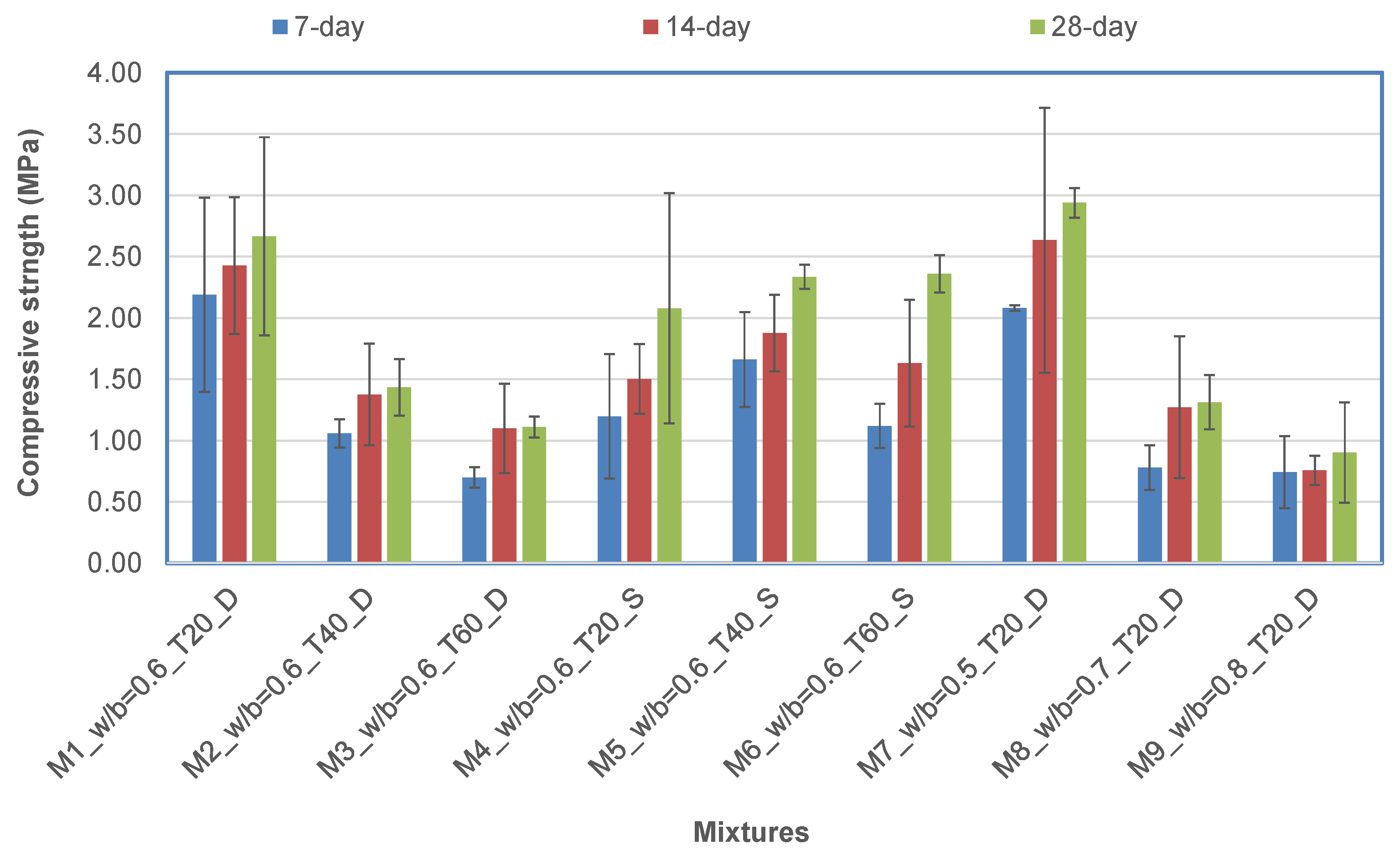
The compressive strength of NAAC generally increased with moist curing conditions, the increase in curing temperature, and the decrease in the water-to-binder ratio;
(2)
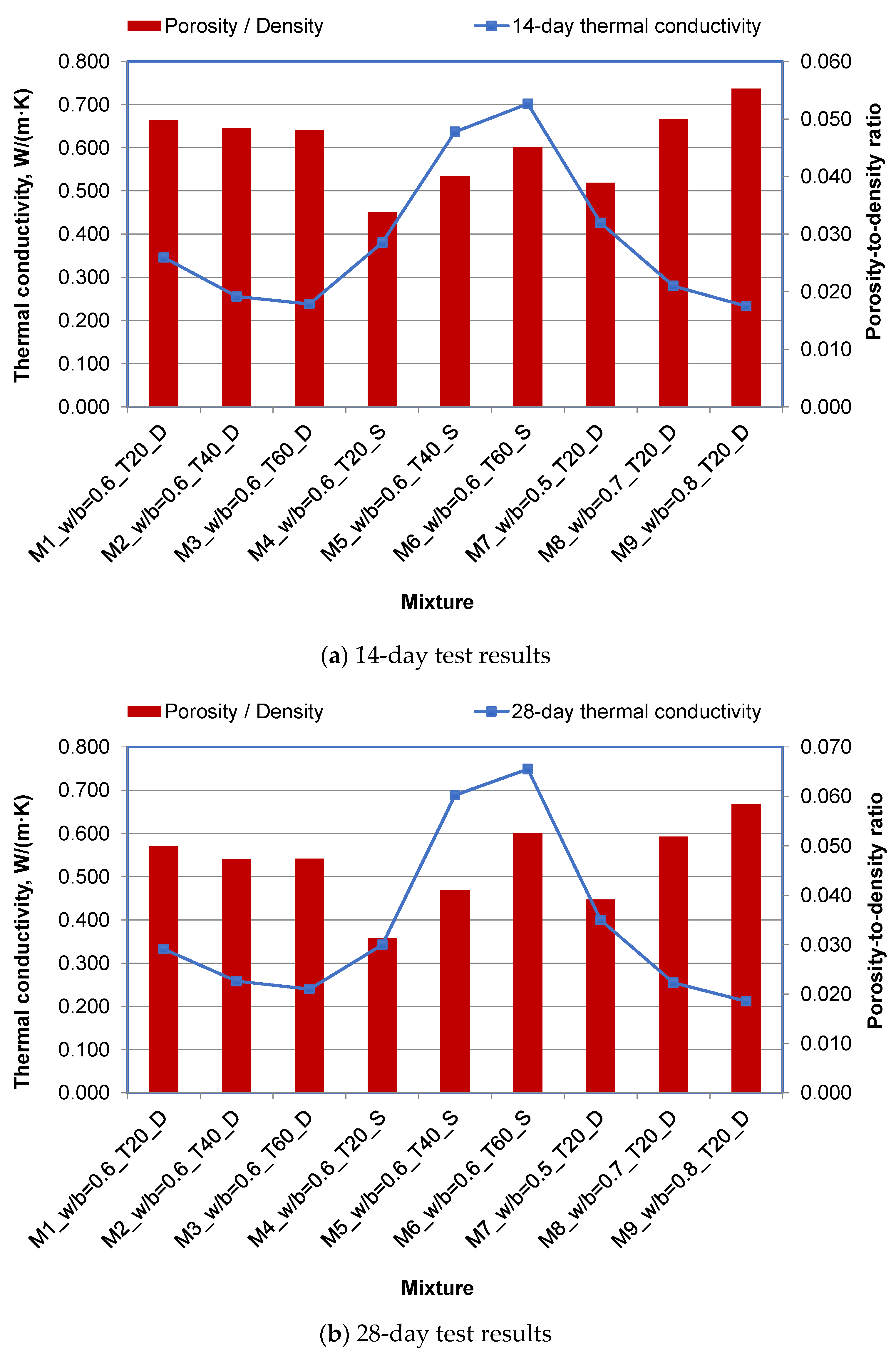
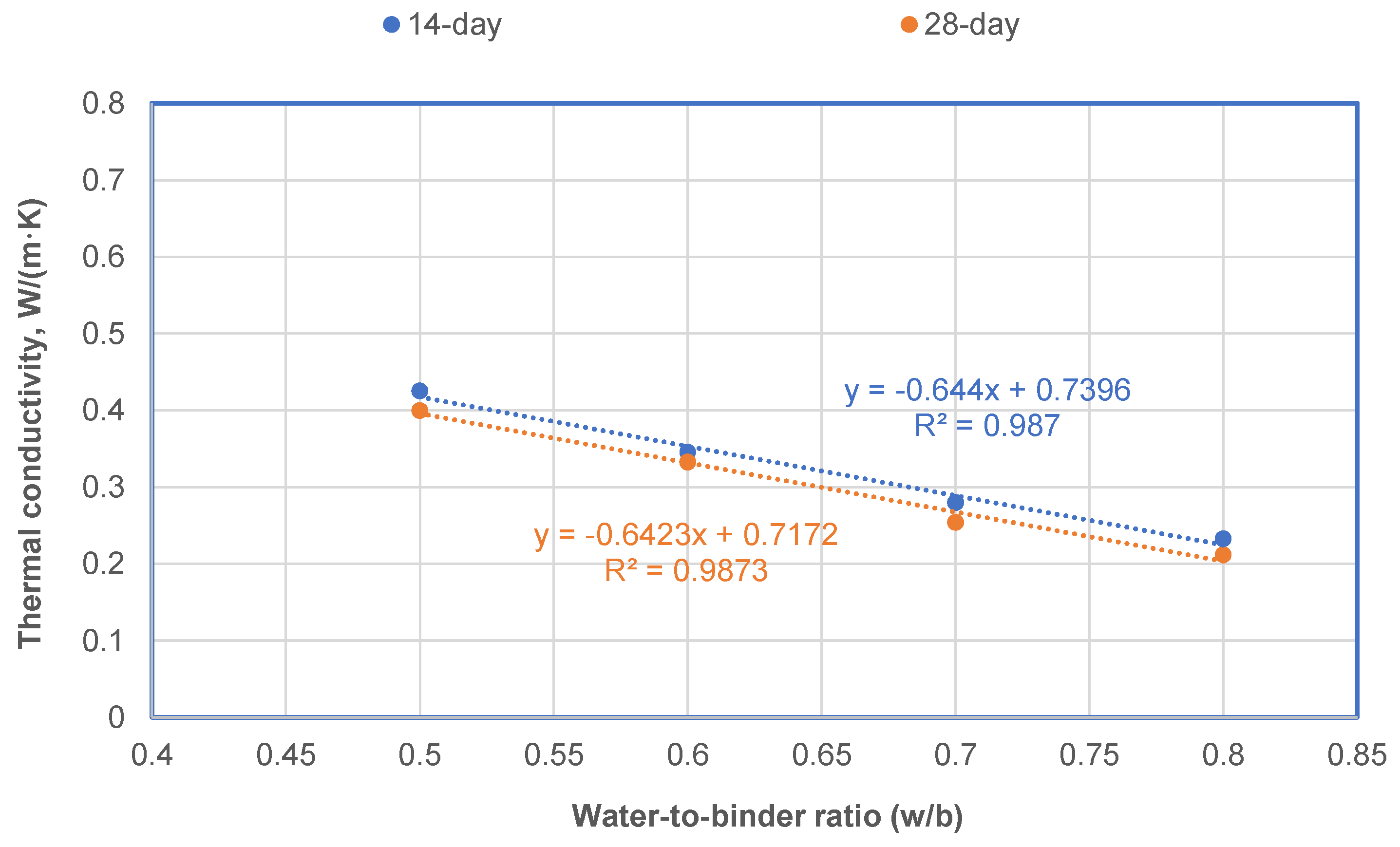
The concrete mixtures with higher porosity and lower density had low λ values, regardless of curing age;
(3)
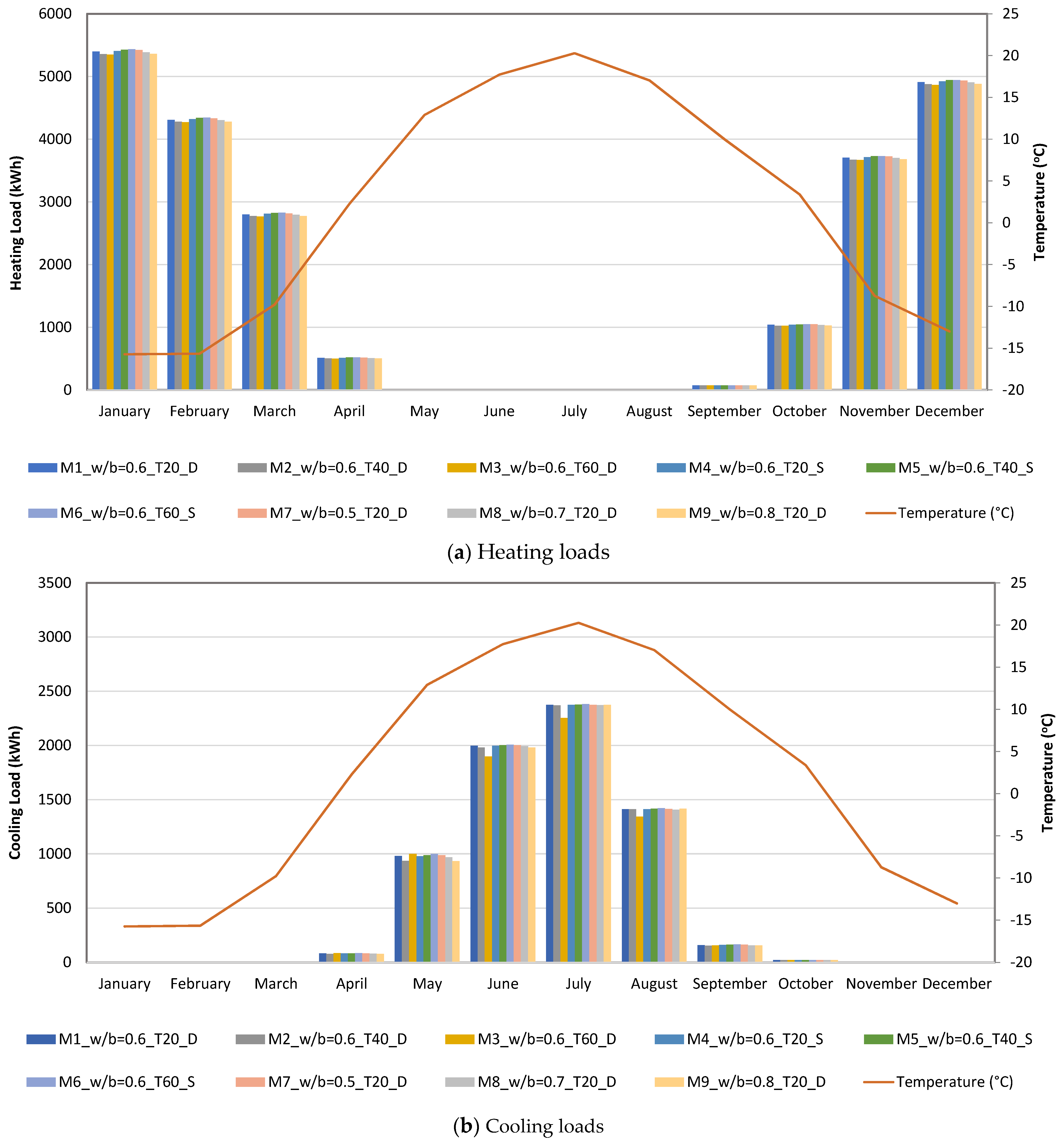
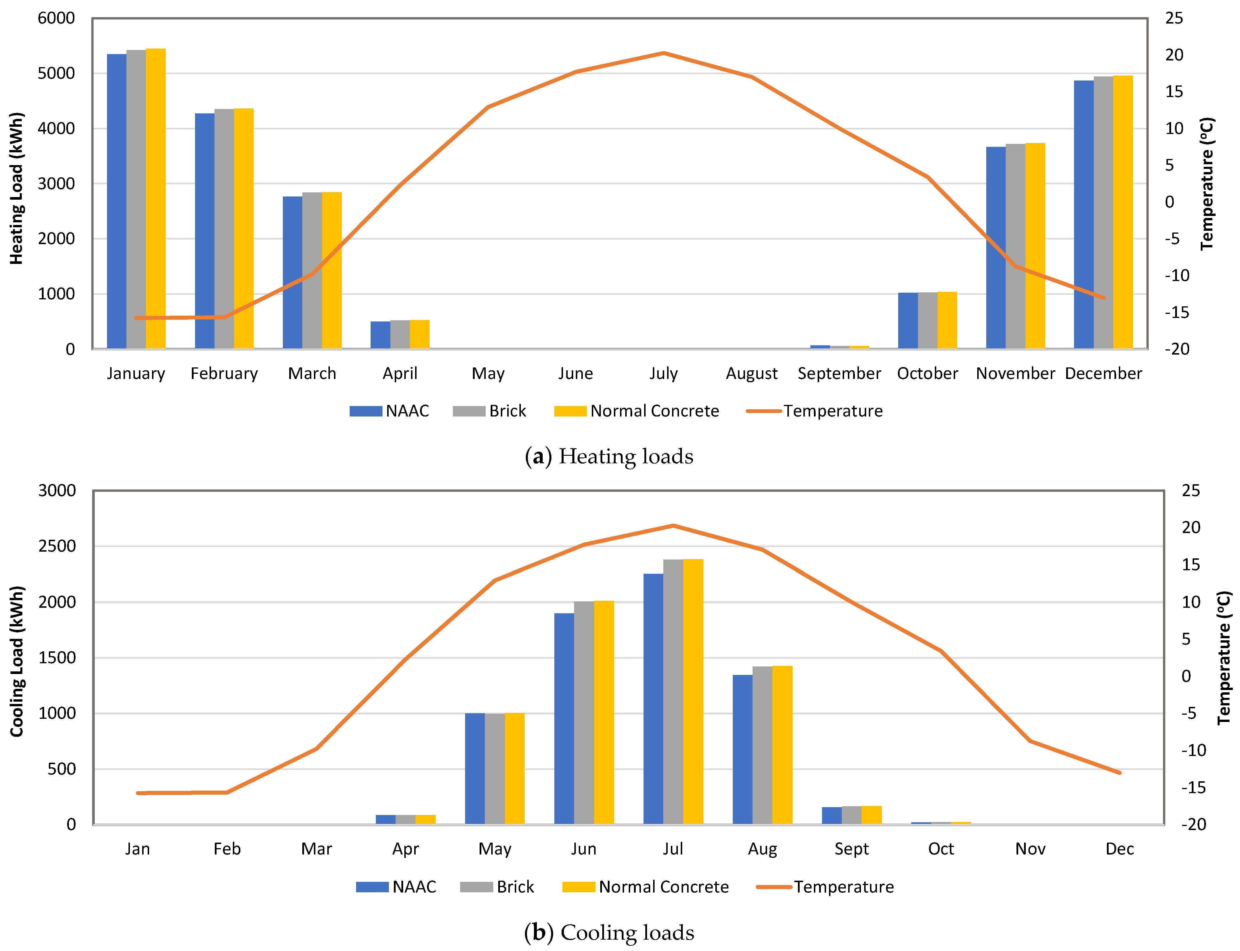
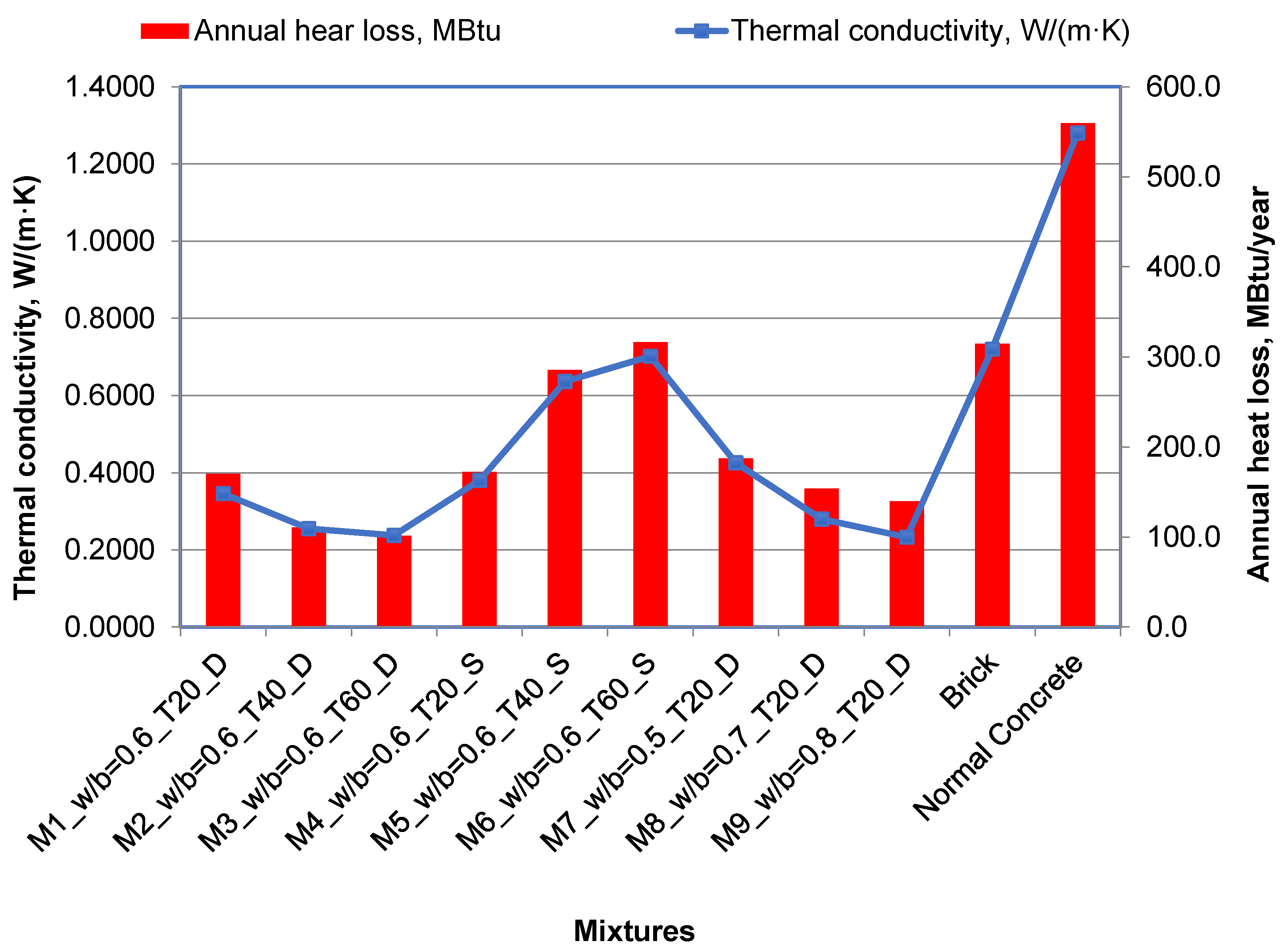
DesignBuilder simulation results indicate that NAAC with lower λ values led to lower heating and cooling energy needs;
(4)
The largest area in the house consumed more heating and cooling energy, regardless of mixture type;
(5)
Because the heating and cooling loads of NACC were lower than those of brick and normal concrete, the house with NACC walls was more efficient in saving source energy and site energy, as well as in reducing material costs;
(6)
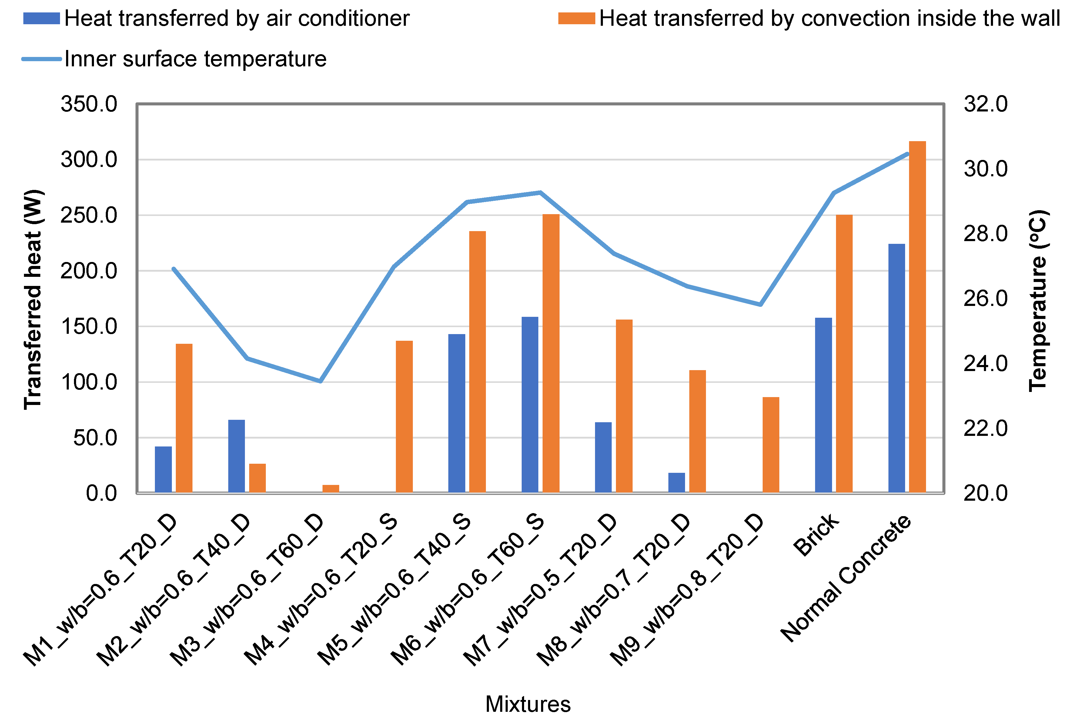
Evaluation results of annual heat loss and heat transfer were consistent with DesignBuilder simulation results, showing that the use of NAAC conserves more energy than brick or normal concrete.
The thermal properties of NAAC are remarkably affected by various ingredients of concrete and hardened properties of concrete, such as density and porosity. The NAAC in this study was made from conventional materials such as cement, lime, silica-rich sand, and aluminum powder. Therefore, a more sustainable approach could be adopted if the NAAC was made of industrial byproducts such as fly ash and ground granulated blast-furnace slag (GGBFS), or solid municipal waste materials such as waste glass bottles.

Author Contributions

Conceptualization, C.-S.S. and D.Z.; data curation, A.U.; formal analysis, I.M. and A.U.; funding acquisition, C.-S.S. and J.K.; investigation, C.-S.S., I.M., and A.U.; methodology, C.-S.S., I.M., and D.Z.; project administration, J.K.; resources, J.K.; software, I.M.; supervision, C.-S.S., D.Z., and J.K.; validation, I.M.; visualization, I.M.; writing—original draft, C.-S.S.; writing—review and editing, C.-S.S., D.Z., and J.K. All authors have read and agreed to the published version of the manuscript.

Funding

Nazarbayev University funded this research under Faculty Development Competitive Research Program Grant No. 021220FD1351; the authors are grateful for this support. Any opinions, findings, conclusions, or recommendations expressed in this material are those of the author(s), and do not necessarily reflect the views of Nazarbayev University.

Institutional Review Board Statement

Not Applicable.

Informed Consent Statement

Not Applicable.

Data Availability Statement

The data used to support the findings of this study are included within the article. The original details of the data presented in this study are available on request from the corresponding author.

Acknowledgments

The authors appreciate Ecoton Company and the National Laboratory of Astana (NLA) at Nazarbayev University for their provision of the raw materials and equipment used in this work.

Conflicts of Interest

The authors declare no conflict of interest. The funders had no role in the design of the study, in the collection, analyses, or interpretation of data, in the writing of the manuscript, or in the decision to publish the results.

References

  1. Shon, C.-S.; Mukashev, T.; Lee, D.; Zhang, D.; Kim, J.R. Can Common Reed Fiber Become an Effective Construction Material? Physical, Mechanical, and Thermal Properties of Mortar Mixture Containing Common Reed Fiber. Sustainability 2019, 11, 903. [Google Scholar] [CrossRef] [Green Version]
  2. Real, S.; Gomes, M.D.G.; Rodrigues, A.M.; Bogas, J.A. Contribution of structural lightweight aggregate concrete to the reduction of thermal bridging effect in buildings. Constr. Build. Mater. 2016, 121, 460–470. [Google Scholar] [CrossRef]
  3. Sobhy, I.; Brakez, A.; Benhamou, B. Analysis for thermal behavior and energy savings of a semi-detached house with different insulation strategies in a hot semi-arid climate. J. Green Build. 2017, 12, 78–106. [Google Scholar] [CrossRef]
  4. Astana Current Weather Report, World Weather Online. Available online: https://www.worldweatheronline.com/lang/ru/astana-weather-averages/astana/kz.aspx (accessed on 26 September 2021).
  5. Committee of Atomic and Energy Supervision and Control. Available online: http://en.kaenk.energo.gov.kz/ (accessed on 26 September 2021).
  6. Energy Situation in Astana. Urban Corners. Available online: https://www.urbaneecken.org/en/energy-situation-in-astana/ (accessed on 26 September 2021).
  7. Narayanan, N.; Ramamurthy, K. Structure and properties of aerated concrete: A review. Cem. Concr. Compos. 2000, 22, 321–329. [Google Scholar] [CrossRef]
  8. Qu, M.-L.; Tian, S.-Q.; Fan, L.-W.; Yu, Z.-T.; Ge, J. An experimental investigation and fractal modeling on the effective thermal conductivity of novel autoclaved aerated concrete (AAC)-based composites with silica aerogels (SA). Appl. Therm. Eng. 2020, 179, 115770. [Google Scholar] [CrossRef]
  9. Soultana, A.; Galetakis, M. Utilization of quarry dust and calcareous fly ash for the production of lightweight cellular micro-concrete—synthesis and characterization. Buildings 2020, 10, 214. [Google Scholar] [CrossRef]
  10. Ulykbanov, A.; Sharafutdinov, E.; Chung, C.-W.; Zhang, D.; Shon, C.-S. Performance-based model to predict thermal conductivity of non-autoclaved aerated concrete through linearization approach. Constr. Build. Mater. 2019, 196, 555–563. [Google Scholar] [CrossRef]
  11. ACI Committee 523. Guide for Design and Construction with Autoclaved Aerated Concrete Panels, ACI 523.4R-09; American Concrete Institute: Farmington Hills, MI, USA, 2009. [Google Scholar]
  12. Hlaváček, P.; Šmilauer, V.; Škvára, F.; Kopecký, L.; Šulc, R. Inorganic foams made from alkali-activated fly ash: Mechanical, chemical and physical properties. J. Eur. Ceram. Soc. 2015, 35, 703–709. [Google Scholar] [CrossRef]
  13. Walczak, P.; Szymański, P.; Różycka, A. Autoclaved aerated concrete based on fly ash in density 350kg/m3 as an environmentally friendly material for energy-efficient constructions. Procedia Eng. 2015, 122, 39–46. [Google Scholar] [CrossRef] [Green Version]
  14. Ropelewski, L.; Neufeld, R. Thermal inertia properties of autoclaved aerated concrete. J. Energy Eng. 1999, 125, 59–75. [Google Scholar] [CrossRef]
  15. Jones, M.; McCarthy, A. Utilising unprocessed low-lime coal fly ash in foamed concrete. Fuel 2005, 84, 1398–1409. [Google Scholar] [CrossRef]
  16. Radhi, H. A systematic methodology for optimising the energy performance of buildings in Bahrain. Energy Build. 2008, 40, 1297–1303. [Google Scholar] [CrossRef]
  17. Drochytka, R.; Zach, J.; Korjenic, A.; Hroudová, J. Improving the energy efficiency in buildings while reducing the waste using autoclaved aerated concrete made from power industry waste. Energy Build. 2013, 58, 319–323. [Google Scholar] [CrossRef]
  18. Aybek, H. Energy Performance Evaluation of AAC; The University of Alabama at Birmingham: Birmingham, AL, USA, 2013. [Google Scholar]
  19. Kaşka, Ö.; Yumrutaş, R. Comparison of experimental and theoretical results for the transient heat flow through multilayer walls and flat roofs. Energy 2008, 33, 1816–1823. [Google Scholar] [CrossRef]
  20. Heathcote, K. Comparison of the Summer Thermal Performance of Three Test Buildings with that Predicted by the Admittance Procedure. Arch. Sci. Rev. 2008, 51, 31–38. [Google Scholar] [CrossRef]
  21. Machrafi, H.; Lebon, G. Size and porosity effects on thermal conductivity of nanoporous material with an extension to nanoporous particles embedded in a host matrix. Phys. Lett. A 2015, 379, 968–973. [Google Scholar] [CrossRef]
  22. Bhattacharjee, B.; Krishnamoorthy, S. Permeable Porosity and Thermal Conductivity of Construction Materials. J. Mater. Civ. Eng. 2004, 16, 322–330. [Google Scholar] [CrossRef]
  23. ASHRAE. ASHRAE Handbook-Fundamentals. In American Society of Heating, Refrigerating, and Air-Conditioning Engineers, USA; ASHRAE: Atlanta, GA, USA, 2017. [Google Scholar]
  24. Thomas, L.C. Mass Transfer Supplement—Heat Transfer; Prentice Hall: Hoboken, NJ, USA, 1991. [Google Scholar]
  25. Site vs. Source Energy. ArchToolBox. 2021. Available online: https://www.archtoolbox.com/materials-systems/sustainability/site-vs-source-energy.html (accessed on 26 September 2021).
  26. Zhao, Z.; Yang, X.; Qu, X.; Zheng, J.; Mai, F. Thermal insulation performance evaluation of autoclaved aerated concrete panels and sandwich panels based on temperature fields: Experiments and simulations. Constr. Build. Mater. 2021, 303, 124560. [Google Scholar] [CrossRef]
  27. Nicol, J.F.; Humphreys, M.A. Adaptive thermal comfort and sustainable thermal standards for buildings. Energy Build. 2002, 34, 563–572. [Google Scholar] [CrossRef]
Figure 1. Diagram of research scope and experimental program.
Buildings 11 00610 g001
Figure 2. Compressive strength development of each mixture.
Buildings 11 00610 g002
Figure 3. Relationship between thermal conductivity and porosity-to-density ratio.
Buildings 11 00610 g003
Figure 4. Effect of water-to-binder ratio (w/b) on thermal conductivity at 14 days and 28 days.
Buildings 11 00610 g004
Figure 5. A typical 2-story residential house model in Nur-Sultan for energy simulation.
Buildings 11 00610 g005
Figure 6. One-dimensional steady-state model.
Buildings 11 00610 g006
Figure 7. Monthly heating and cooling loads of 9 NAAC mixtures.
Buildings 11 00610 g007
Figure 8. Comparison of monthly heating and cooling loads of NAAC, brick, and normal concrete.
Buildings 11 00610 g008
Figure 9. Annual heat loss of NAAC mixtures, brick, and normal concrete.
Buildings 11 00610 g009
Figure 10. Heat transfer results through a house wall.
Buildings 11 00610 g010
Table 1. Mixture proportions of non-autoclaved aerated concrete.
MixtureUnit Weight (kg/m3)
Sand 1Sand 2Sand 3CementLimeWaterAluminum Powder
M1_w/b = 0.6_T20_D3363793394051983601.62
M2_w/b = 0.6_T40_D3363793394051983601.62
M3_w/b = 0.6_T60_D3363793394051983601.62
M4_w/b = 0.6_T20_S3363793394051983601.62
M5_w/b = 0.6_T40_S3363793394051983601.62
M6_w/b = 0.6_T60_S3363793394051983601.62
M7_w/b = 0.5_T20_D3363793394402293351.62
M8_w/b = 0.7_T20_D3363793393182203781.62
M9_w/b = 0.8_T20_D3363793393201763971.62
Note: M#: mixture number; w/b: water-to-binder ratio; T: curing temperature; D: dried condition; S: saturated condition.
Table 2. Test parameter variables.
Test ParameterLevels
Curing age3, 7, 14, or 28 days
Curing temperature20 °C, 40 °C, or 60 °C
Humidity conditionsDry or moist (saturated)
Water-to-binder ratio0.5, 0.6, 0.7, or 0.8
Table 3. House geometry components for the simulation.
ComponentValue
Floor height7 m (22.97 ft)
Perimeter of house40 m (131.23 ft)
Total area of house280 m2 (3013.89 ft2)
Thickness of wall layer300 mm (11.81 in.)
Thermal conductivity of mixture 30.2315 W/m·K (1.605 Btu·in/h·ft2·F)
Table 4. Properties of wall structure materials.
MaterialsThickness (mm)Thermal Conductivity (W/m·K)Specific Heat (J/kg·K)Density (kg/m3)Cost (GBP/kg)
Decorative stucco100.691884018585.26
Reinforcing mesh20.3100010000.68
Stucco100.691884018582.02
Mineral wool1500.055084014037.90
NAAC3000.2315600111332.16
Brick3000.72840192031.01
Normal concrete3001.81000240028.31
Gypsum plastering100.168307850.081
Table 5. Conditions of one-dimensional heat transfer model.
ElementCondition
Outdoor temperature, T∞1 (°C)35
Indoor temperature, T∞2 (°C)23
Outer wall surface temperature, T1 (°C)32
Length of the wall (1 room), L (m)4
Height of the wall, h (m)3.5
Thickness of the wall, ∆x (m)0.3
Thermal conductivity, λ (W/(m·K))NAAC0.2315
Brick0.72
Normal concrete1.8
Table 6. Heating and cooling energy consumption for each room using mixture 3.
FloorRoomHeating Energy (kWh)Cooling Energy (kWh)
AnnualMaximumAverageAnnualMaximumAverage
First floorGuest room3142691.1261.8403.0157.133.6
Bathroom/WC831.7177.269.377.033.86.4
Kitchen, dining room, and hall6026.81495.1502.2826.5387.368.9
Family room3595.3788.8299.6405.516933.8
Second floorMaster bedroom (MB)3081.3696.4256.8380.4156.231.7
Bathroom/WC 11060.0225.588.3122.751.810.2
Bedroom 12711.1594.9225.9345.5145.528.8
Wardrobe686.7143.257.279.535.86.6
Bedroom 22374.9550.9197.9511.7194.642.6
Bathroom/WC 2773.9167.264.5104.345.78.7
Open space3353.6800.6279.5601.2254.750.1
Total energy consumption27,637.76330.72303.13857.41631.5321.5
Table 7. Cost, total site energy, and total source energy.
MaterialsCost (GBP)Site Energy (kWh)Site Energy Saving (%)Source Energy (kWh)Source Energy Saving (%)
NAAC2781336210.21 118553.77
Brick4144037402.733.291232733.98
Normal concrete4116038103.05.231253385.72
Table 8. Heat transfer results.
Mixtureλ (W/(m·K))Q1 (W)Q2 (W)∆Q (W)T2 (°C)
M1_w/b = 0.6_T20_D0.389192.4134.341.926.9
M2_w/b = 0.6_T40_D0.252492.426.565.924.2
M3_w/b = 0.6_T60_D0.231592.47.584.923.4
M4_w/b = 0.6_T20_S0.394192.4137.244.827.0
M5_w/b = 0.6_T40_S0.653292.4235.4143.029.0
M6_w/b = 0.6_T60_S0.723492.4250.9158.529.3
M7_w/b = 0.5_T20_D0.428792.4156.163.727.4
M8_w/b = 0.7_T20_D0.352492.4110.618.326.4
M9_w/b = 0.8_T20_D0.319792.486.46.025.8
Brick0.720092.4250.2157.829.3
Normal concrete1.80092.4341.83249.4430.9
Note: M#: mixture number; w/b: water-to-binder ratio; T: curing temperature; D: dried condition; S: saturated condition.
Publisher’s Note: MDPI stays neutral with regard to jurisdictional claims in published maps and institutional affiliations.

