1. Introduction
The technologies related to producing freeform architecture are evolving [
1]. This can be confirmed by comparing recent architecture to architecture from the more distant past [
2]. The development of computer technologies has allowed much more free design of buildings with curved and twisted structures [
3,
4,
5,
6]. However, while it may be easy to design freeform buildings using computer software, the paneling, production, and construction required to realize those buildings remains very challenging and expensive [
7]. The curved concrete facades of freeform buildings cannot be produced with a single massive mold, they must be constructed by dividing the façade into smaller panels. Freeform panels can be divided into flat, single, or double curved lines. To manufacture them, a formwork must be produced individually for each panel. The recently completed National Museum of Qatar used approximately 76,000 freeform concrete panels to produce a structure composed of 316 intersecting discs in various orientations [
8]. About 3000 molds were produced to make all the concrete panels of different shapes and sizes [
9].
To address the issues around producing freeform concrete panels, reusable molds that take advantage of CNC technologies are being developed, but this is still labor intensive and generates high volumes of waste. The CNC technology is used to create curves in the lower part of the mold for the concrete panels while the curves in the upper part of the mold are plastered. The corresponding curves on the upper and lower parts of the mold cannot be created simultaneously, the precision of the shape is reduced due to the manual work on the upper surface. The precision of the panel also differs depending on the skills of the worker, and molds by the same worker will show different levels of precision; this can result in the panel having quality issues [
10,
11]. Therefore, technologies that can simultaneously produce precise curves in both the upper and lower parts of the same mold are needed. Motivated by the problems outlined above, in this study we introduce a double-sided multipress tool that produces two sides of a freeform concrete panel. Furthermore, operational technology for accurately producing both sides of the freeform concrete panels using the developed equipment is presented. This study had three objectives.
Develop a double-sided multipoint press.
Perform experiments to demonstrate this tool’s ability to produce curved panels.
Propose operational technology for manufacturing freeform concrete panels.
2. Literature Review
CNC technologies have continuously improved freeform element production technologies [
12]. In the case of the freeform concrete production sector, EPS (Expandable Polystyrene) [
13,
14], wood [
15], and textiles [
16,
17] processed by CNC have been successfully used to manufacture panels. CNC technology helps to ensure the accuracy of the concrete shapes produced and is partially reusable, but the materials themselves cannot be reused. If all panels have unique shapes and each panel requires a mold, then if the molds cannot be reused, the costs will be significant.
Oesterle et al. [
18] developed a mold based on wax that can be reused. However, only the concepts related to the equipment and technology were proposed; there was no mention of the problems that can occur with wax when making molds such as the hardening time of wax, crystallization, cracking, etc., nor were solutions for these issues suggested. Furthermore, the shape the wax molds could produce and the errors in the process were not verified, therefore, this proposal is still very much in the idea stage. Lee [
12] developed PCM manufacturing technology based on CNC that can be reused. However, upper and lower molds must be created to produce a single freeform concrete panel, then in order to reuse the PCM, a considerable amount of time is required for production processes such as melting and hardening. These technologies require two manufacturing processes and the mold itself cannot be transformed.
The most economical solution for producing individual panels with unique shapes is a variable mold [
19]. Variable molds were first mentioned by Renzo Piano in 1960. Piano [
20] suggested that molds could be transformed by adjusting their height with actuators using computer processing technology. Starting with this idea, the variable mold concept has been developed using support structure formats and CNC technology. Huyghe [
21] produced curved panels by carving plywood and inserting thin wires in all of the grooves. However, because of the grooves, the plywood cannot act as a mold on its own, so it was covered with a silicon plate to produce the panel. When producing curved panels, the thickness of the plywood resulted in inaccurate bends, while gaps occurred between the rod and the plywood. Janssen [
19] developed a variable lower mold that can implement both single curved and double curved panels. In order to prevent sag caused by the load of concrete, the shape plate consisted of a wooden strip supported by a pin bed that could move to curve the face of the mold. Concrete cannot be poured directly onto the wooden strips, so additional materials are needed to cover the shape plate. Furthermore, the time required for transforming the mold to the appropriate shape must also be taken into consideration. Eigenraam [
22] used plastic strips to create curved panels, a notch was carved into the strips to create gentle curves. Upon creating curved concrete panels with the developed mold, an error of less than four millimeters was measured. Though this is a small error, the concrete panels were not manufactured, and the rigidity of the mold could not be confirmed. A variable mold using CNC technology was developed [
23,
24]. A rod system with a silicone protective membrane was used to create a mold that could adapt its shape. As the height of the rods changed, the protective surface could take on the shape of various smooth curves. However, since this equipment only implements curves on the lower part of the mold, the upper part needs to be created manually.
Jeong [
5] proposed the concept of a double-sided multipoint press that could simultaneously produce the curved upper and lower parts of the mold needed to fabricate freeform concrete panels. Plans to improve the accuracy of the mold shapes by analyzing problems related to producing freeform concrete panels have also been proposed. However, the equipment used, operating principles, performance, and many other details have not yet been discussed while the panels themselves were not manufactured, so verification of the equipment used to produce these freeform panels has yet to be conducted.
Finally, the focus of this work is to build on the concepts introduced in our previous paper on freeform concrete panel production technology [
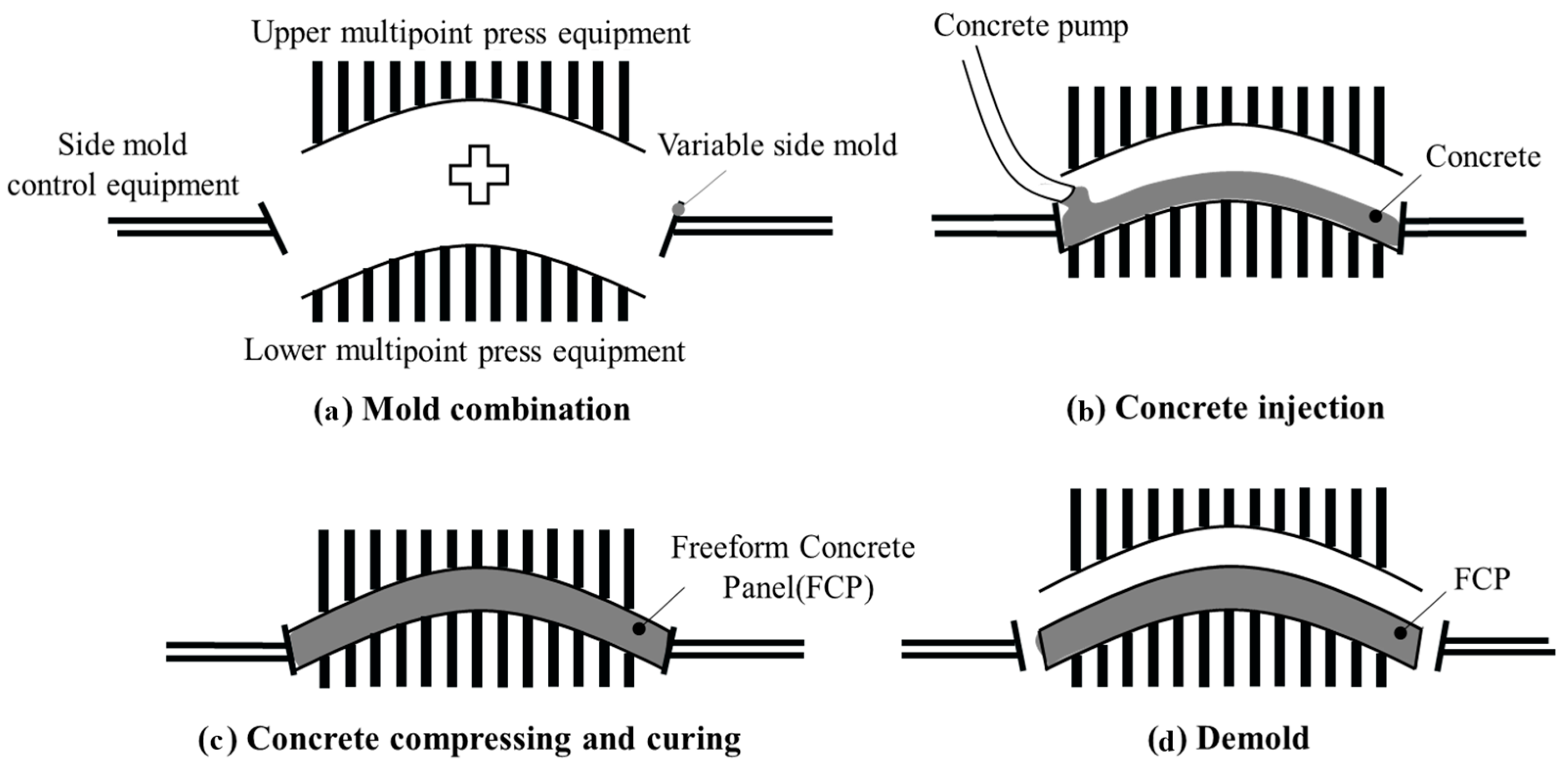
25]. In that paper, the idea for freeform concrete panel production equipment that included a double-sided multipoint press that produced curves on both sides of a panel, a side mold control equipment that adjusts the side angles of the panel, and a variable side mold that transforms according to the desired curvature of panel was introduced. The production process was divided into four stages: combination, injection, compression and curing, as well as demolding, as shown in
Figure 1. The upper, lower, and side parts of the mold were combined to the form the shape of the panel before concrete was injected for production. The injected concrete was compressed from all directions by the mold and then cured in place. Once the concrete was cured, the mold was removed, and production was complete. This paper focuses on developing the double-sided multipoint press CNC introduced in our previous work.
3. Development of Double-Sided Multipoint Press CNC
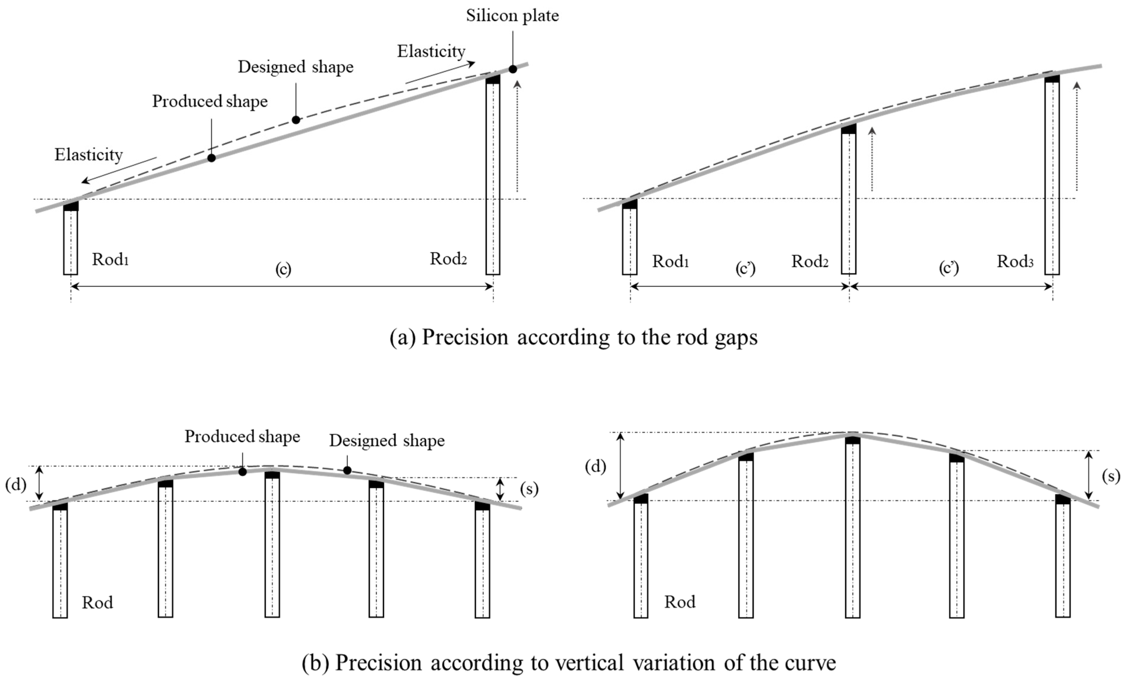
Technologies that can produce freeform concrete panels tend to be composed of support structures combined with a shape plate, in this technology, a rod type support structure that takes advantage of CNC is used while the shape plate is made from silicone. The two elements, fixed together by bolts, produce curved surfaces according to the rod heights. The silicone plate must be very elastic because it is bolted to the moving rods so will be deformed into many different shapes. When the rods rise up, the silicone plate becomes stretched and errors can occur between the shapes of the designed and produced panels, as shown in
Figure 2. However, by increasing the number of rods and reducing the gap between rods this error is reduced. In other words, in order to implement precise shapes, it is necessary to choose the appropriate rod gap(c). Even if the rod gap is small, significant errors can occur due to the height difference(s) between rods. The height differences between the rods increase as the vertical variation of the curve(d) surface of the panel increases [
10]. To reduce the difference in height between rods, the gap must be further reduced. Therefore, in order to minimize errors, appropriate rod gaps must be set. Considering this, the rod spacing (C’) in
Figure 2a is designed to be 100 mm.
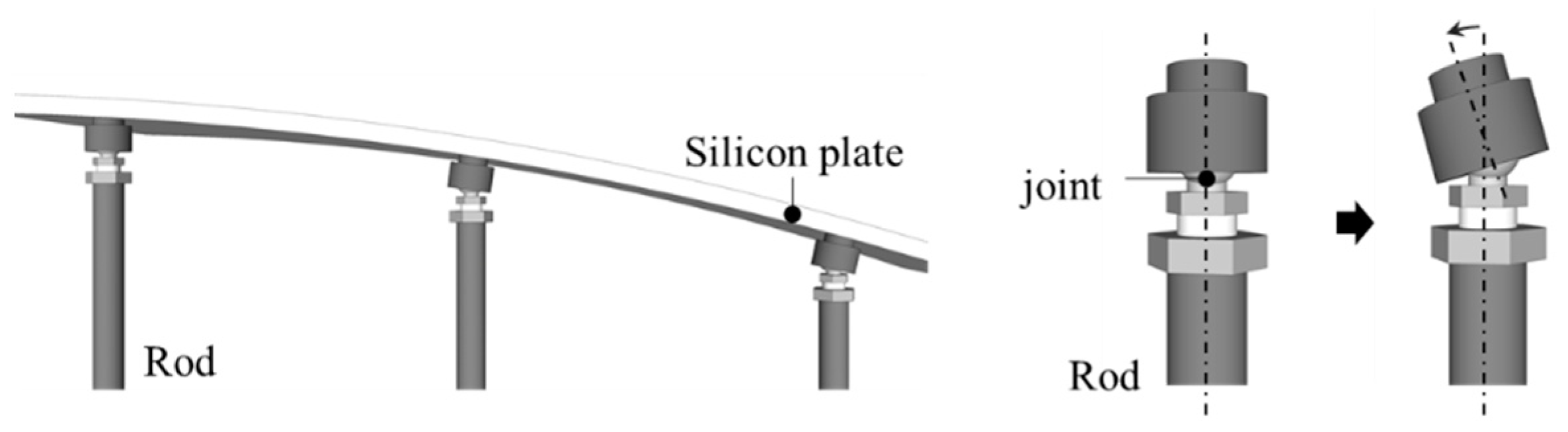
Errors in the shape of the produced panels can be minimized by adjusting the rod gap but whenever we combine silicone plates and rods like this there are certain limitations in implementing curved panels exactly as they were designed. The silicone plate produces curves according to the height difference between the rods supporting the plate. However, as the silicone plate is bolted to the rod, twisting can occur at the combining point, making it impossible to produce smooth curves. Therefore, the bolted points between the plate and the rods were allowed to rotate by attaching joints to the end of each rod as shown in
Figure 3.
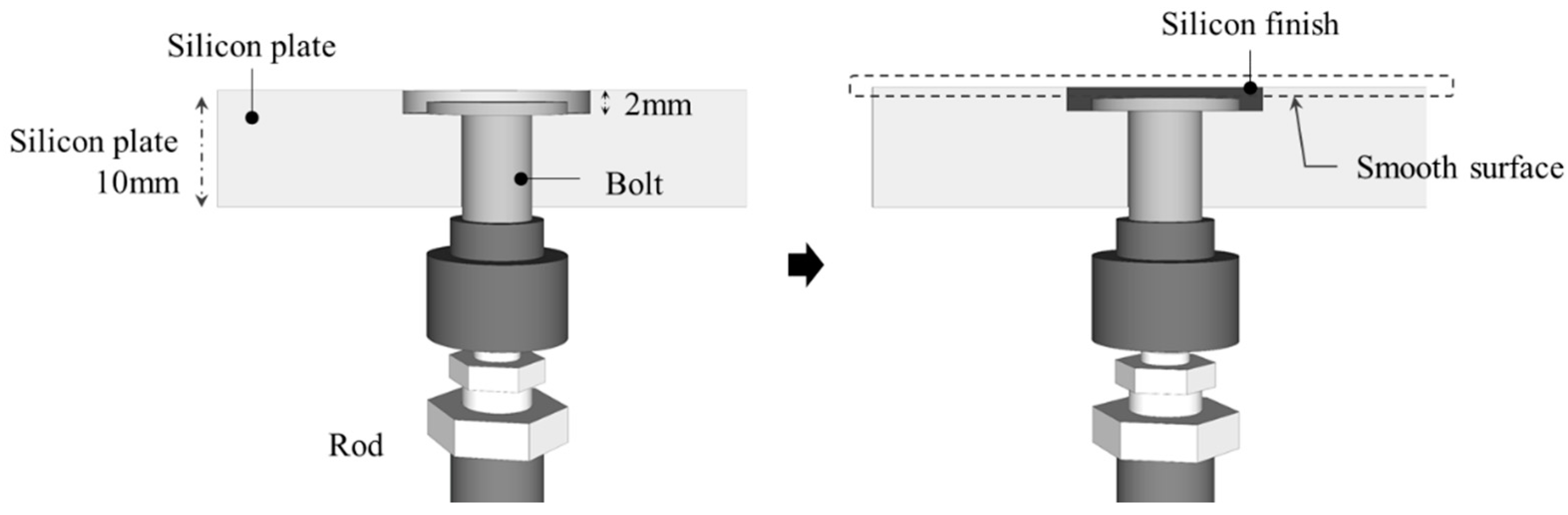
The concrete is poured on the silicone plate so its surface must be smooth. However, as the silicone plate and rods are attached by bolts, the bolts protrude above the surface. When the freeform concrete panels are produced with plates with a protruding surface, the quality is reduced and additional processing is required. Therefore, in order to improve the surface finish, the silicon plate is bolted to the rod and the surface is finished by injecting silicon as shown in
Figure 4.
The double-sided multipoint press produces freeform concrete panels in combination with side shape control equipment and the variable side molds discussed in the concept presented by Yun [
25]. The side mold control forms a circular perimeter from a plan view to produce various shapes. Therefore, the double-sided multipoint press surface is also a circle from a plan view so all parts of the mold fit together to produce accurate concrete panels with freeform surfaces, as shown in
Figure 1.
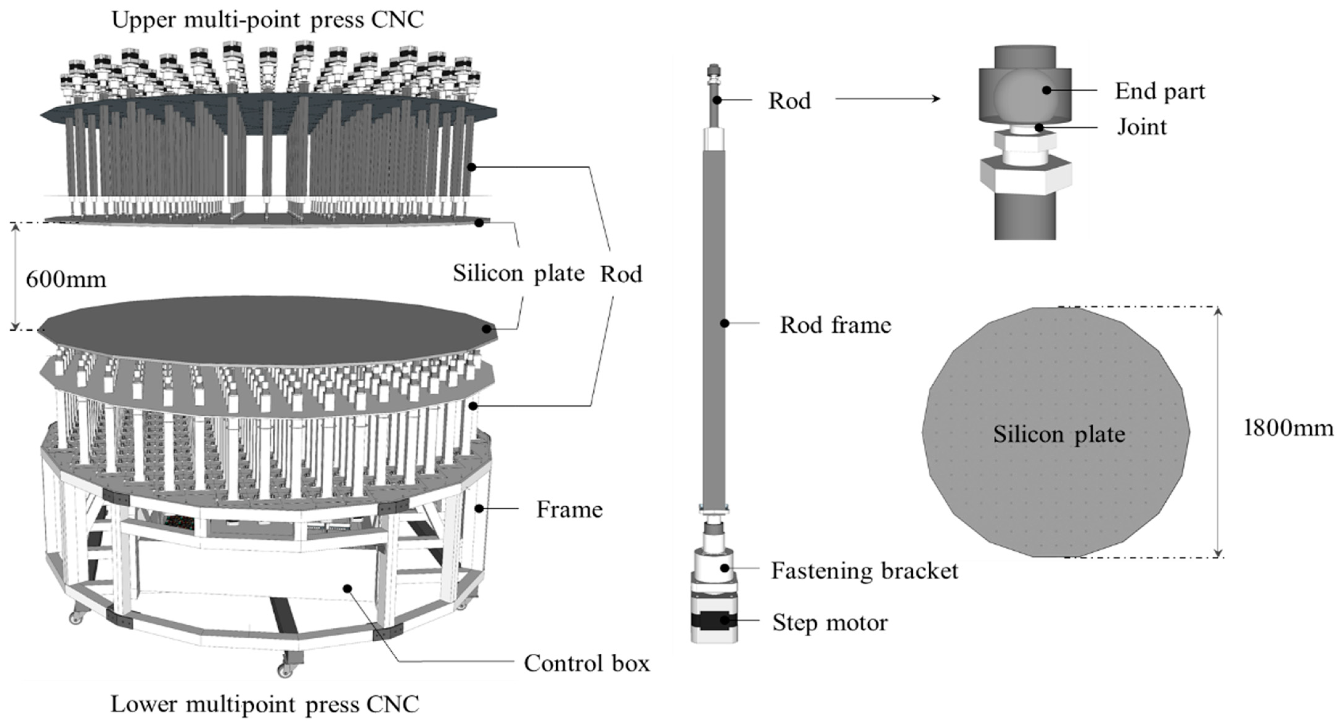
The double-sided multipoint press consists of an upper multipoint press and a lower multipoint press, together they can produce freeform panels using silicon plates and rods. As shown in
Figure 5, each press is composed of rods, a silicone plate, a frame, and a control box. There are a total of 310 rods—89 on the top and 211 on the bottom; the rods are arranged at 150 mm intervals on the top and at 100 mm intervals on the bottom. Each rod is composed of a rod end which is bolted to the silicon plate, joint, rod frame, fastening bracket, and stepper motor. The gap between the upper multipoint press and lower multipoint press is 60 mm; the rods can move up to 300 mm according to the number of motor rotations. The fixed part of the rod is made up of the combining part and joint. The diameter of the silicone plate is 1800 mm and the maximum size of one side of a rectangular freeform concrete panel is 1200 mm while the minimum size for one side is 500 mm.
4. Operational Technology and Curved Surface Implementation Experiment
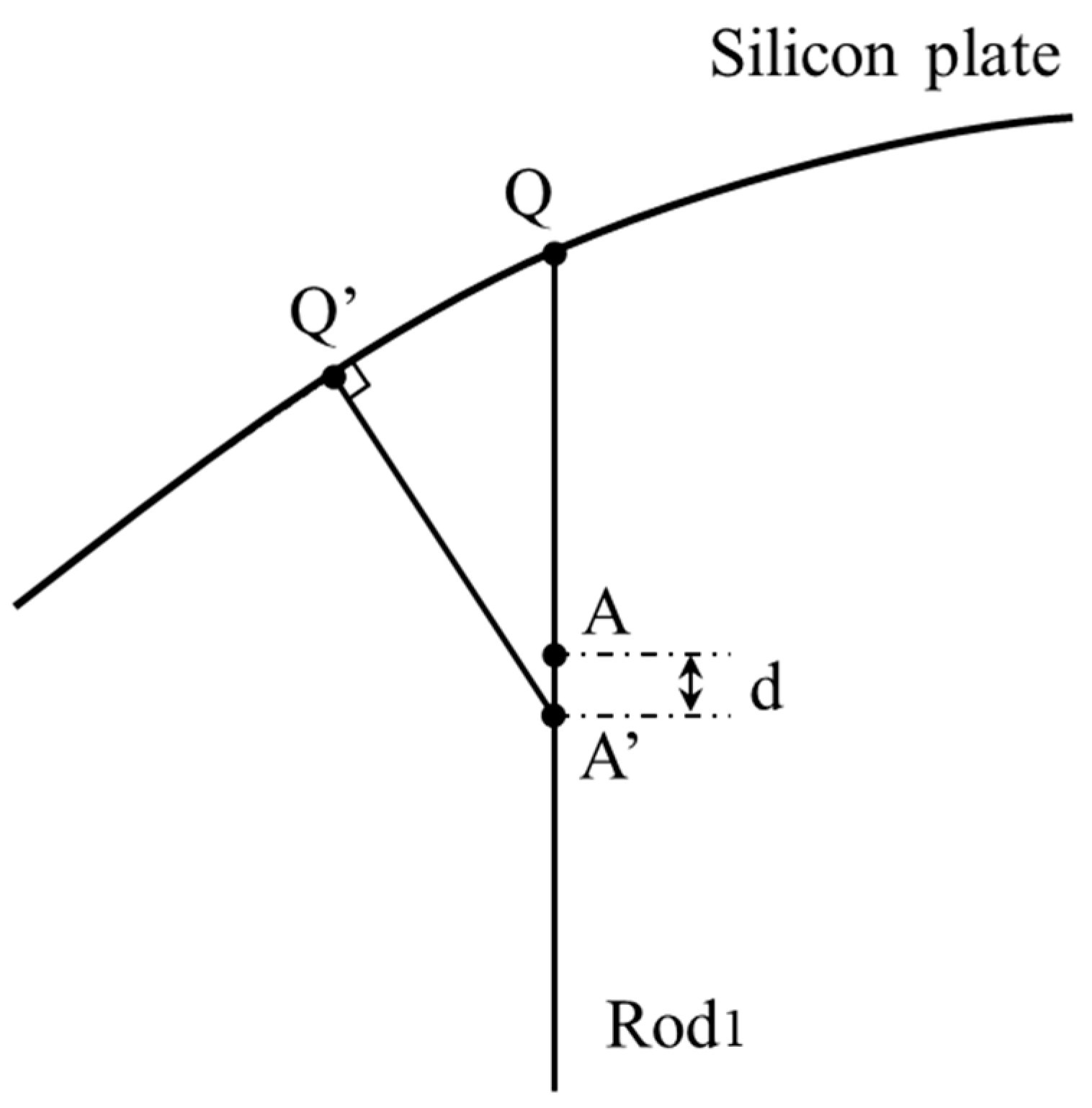
When producing the curved panels, the existence of a joint changes the height the rod should be set to. Rod
1, illustrated in
Figure 6, has a rod end (AQ) and a joint (A) that allows the rod end to rotate. Rod
1 can rotate around the joint at location A. If the AQ of rod
1 does not rotate, then point Q on the silicone plate supports the load. However, as the shape of the silicone plate produces curved surfaces, the rod end of rod
1 rotates in the direction AQ to support the silicone plate.
In this case, the height of rod1 is reduced as much as d. When the rotational angle of the rod end increases, d also increases. In other words, the difference in the height set for the rod (d) according to the angle of the joint is determined by how curved the surface of the silicone plate is. As a result, the heights the rods with joints are set to are smaller than those for rods without joints. Thus, to produce accurate panels, the height set for the rod with a joint must be calculated carefully. However, since the input value is calculated through a complex procedure, this may take a long time. Yet, if the height that would have been set for a rod without a joint is used, the shape of the panels produced will not be accurate. Therefore, it is appropriate to calculate and set the correct height for rods with joints. Even so, there can be errors in the panels produced due to the elasticity of the silicone plate, as such, it is necessary to decide whether this level of error is allowable. Furthermore, if the error due to the elasticity of the silicone plate is large, it is necessary to attempt to correct it through adjusting the heights the rods are set to. Given all the considerations outlined above, it becomes clear that operational technology for accurately producing the freeform concrete panels is needed.
Given the need for the operational technology discussed above, this study conducted curved panel production experiments with a manual multipoint press to understand the operational technology needed for the double-sided multipoint press CNCs. The multipoint press used in the experiments had the same set up as the equipment described above. The rods (6 × 6) were arranged with a 100 mm gap and a silicone plate (600 × 600 × 10) was attached to the tops of the rods. The rods rose and fell as a lead screw rotated to produce the desired curved surface. The experiment was carried out using the following process.
The curved surface of a panel for the silicon plate to produce was designed, and the heights to set the rods to realize that shape were calculated.
The curved surfaces in the mold were implemented and any errors in the shape were analyzed.
Errors in the shape were corrected through reverse engineering.
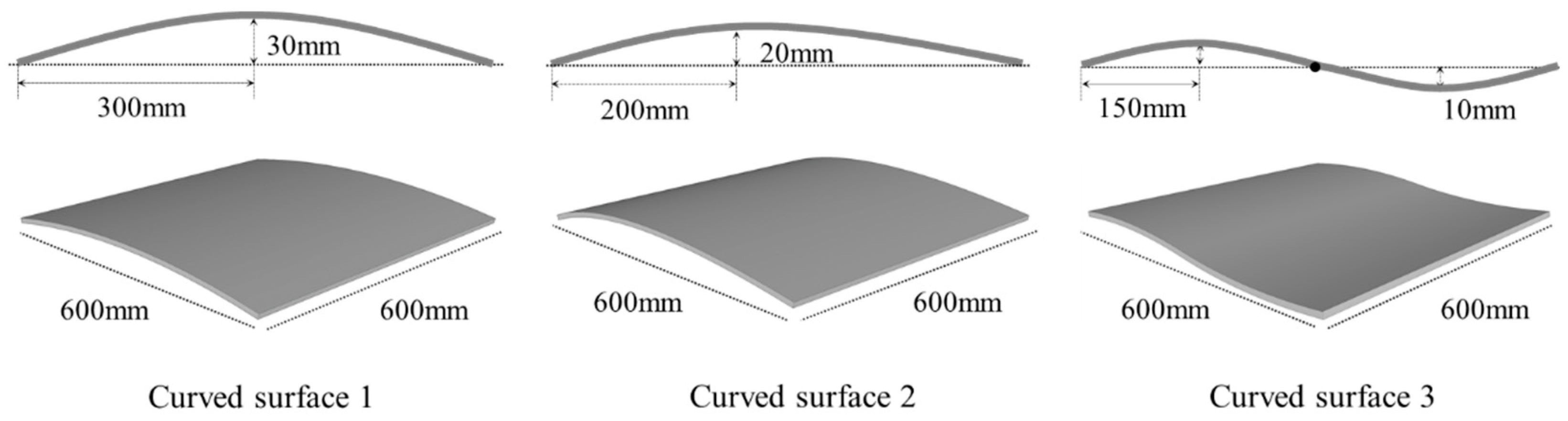
The multipoint press used in the experiment was flexible and could implement a variety of curved surfaces. The silicone plate was set to have three different curved surfaces. Curved surface one, shown in
Figure 7, had no inflection point, and the vertical variation of the curve at 300 mm was 30 mm. Curved surface two had no inflection point, and the vertical variation of the curve at 200 mm was 20 mm. Lastly, curved surface three had an inflection point in the center of the silicone plate and the vertical variation of the curve at the 150 mm and 450 mm point was 10 mm.
All the curved surfaces were designed to have a single curve, so the set heights of rods X
1 to X
6 were the same; the values of X and Y
1 to Y
6 to produce the correct curved surface are shown in
Table 1. X
a is the height that would be set for a rod without joints and X
b is height set for rods with joints. For curve 1, the Y value of X
a was measured in the range from 9.2 mm to 29.2 mm and X
b was measured in the range from 8.5 mm to 29.1 mm. For curve 2, the Y value of X
a was measured in the range from 8.7 mm to 40.9 mm and X
b was measured in the range from 7.9 mm to 40.9 mm. For curve 3, the Y value of X
a was measured in the range from 1.6 mm to 19.6 mm and X
b was measured in the range from 1.4 mm to 19.5 mm. The difference in the heights set (X
a-b) according to the existence of joints in the three types of curve shapes fell in the range from 0.0 mm to 2.0 mm. This difference was very small, but the precise input values were important to match the design as closely as possible, i.e., X
b were used to minimize shape errors.
The rods were raised to their set heights to manipulate the silicon plate to produce a curved surface, as shown in
Figure 8. As any errors in the shape of the plate could not be judged by eye, the errors were analyzed using a 3D scanner (GoCanSpark) and a quality inspection program (VXInspect). Excluding where the silicone plate was supported by the outermost rods, the assessed area of the plate was divided into nine sections and 45 pieces of data were collected. There are no precise regulations on the allowable error for freeform concrete panels, therefore, in this study, we applied the allowable error for plane wall thicknesses of 3% from Korean architecture standards as the standard for freeform concrete panels. The allowable error for the freeform concrete panels with a thickness of 100 mm was chosen to be 3 mm (3%) [
10,
11,
25,
26]. Upon analyzing the shape error, the average error in curved surface one was −1.879 mm and the maximum error was 2.633 mm, as shown in
Table 2. For curved surface two, the average error was −1.933 mm and the maximum error was 2.690 mm. For curved surface three, the average error was −1.074 mm and the maximum error was 3.497 mm. The shape errors were very small, and while shapes one and two were measured to be within the allowable error, shape three exceeded the allowable error. The silicon plate between the rods was stretched into a flat plane due to the elasticity. This elasticity resulted in some deviations from the shape that was designed. This elasticity can have different effects according to the circumstances, for example it is affected by factors such as the type of silicon plate, thickness, appearance, and temperature, also the elasticity at any point on the surface is a direct result of the height differences between the neighboring rods supporting that point. Furthermore, the plate’s elasticity affects the rotation angle of the rod joints. As shown in
Table 3, upon analyzing the errors where the support points of the rods meet the plate, deviations from the designed heights were found. The expected rotation angle of the rods and their heights were calculated beforehand. However, when these values were applied using the actual equipment, the joint rotated more or less than expected due to the elasticity of the silicone plate. Therefore, the actual rod heights that were needed to produce the correct shape were slightly different, the support points become slightly too low because the rod and the support were in the wrong position. In other words, each rod was lower than it should have been to provide the designed support points, causing errors in the shape produced. As such, it was impossible to manufacture panels with a curved surface using the rod heights calculated from the design. The heights of the rods that would produce the exact shape were unknown, and unpredictable shape errors occurred. Therefore, as it is difficult to precisely match the shape produced with the shape designed, in this study, we minimized the shape errors through reverse engineering.
In this study, we adjusted the heights set through reverse engineering. The approach was to raise the load as much as the average of the shape errors analyzed in the first order so that the average became zero. To test this, curved surface three was corrected. Curved surface three needed correction because it exceeded the allowable error proposed. As the average error was −1.074, the rods were too low compared to the designed shape, the rods were raised by the average error and the new shape errors were analyzed. As shown in
Table 4, while in theory the average error of the corrected shape should have been zero, after applying the corrections and measuring the errors again, the error in corrected shape three was found to be 0.671 mm on average, the maximum value was 2.887 mm, and the minimum value was 0.117 mm. The maximum value was reduced by 0.610 mm compared to before the correction, and all errors were measured to be within the allowable error.
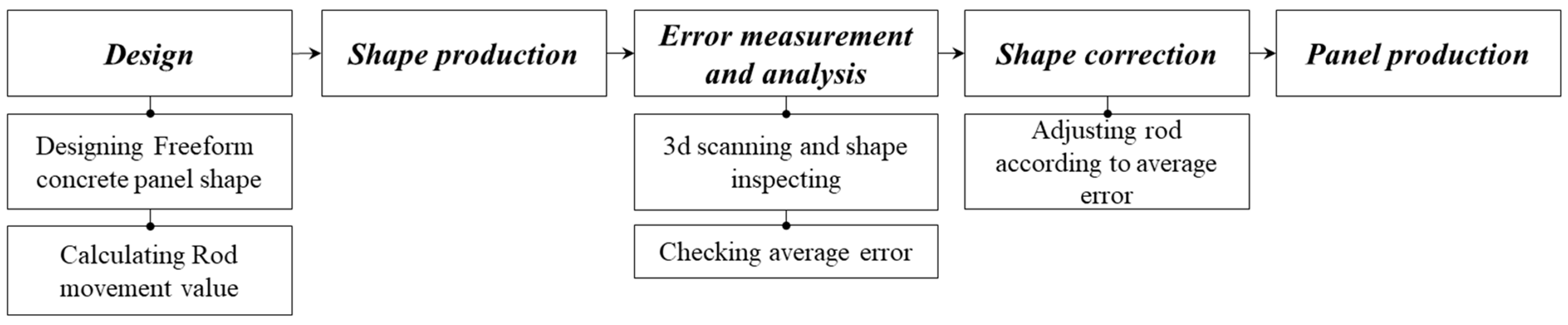
The process for the operational technology to produce freeform concrete panels with the double-sided multipoint press CNC is shown in
Figure 9. (1) Design: The shape of the freeform concrete panel was designed, the heights to set the rods were then calculated. (2) Shape production: The rod heights were entered into the double-sided multipoint press CNC to produce the shape. (3) Error measurement and analysis: Any errors were measured and the average error was checked through 3D scans and shape inspection. (4) Shape correction: The rods were raised or lowered by the average error to correct the shape. (5) Panel production: All molds were assembled and the freeform concrete panel was produced.
The operational technology proposed in this study cannot produce freeform panels that exactly match the designed shape of the lower surface. However, as it is possible to minimize shape errors to allowable levels, our method is a suitable technology for producing freeform concrete panels. However, only the technology for producing freeform concrete panels was proposed in this study, as such, studies that investigate the errors in the panels produced when using this technology are needed.


