Article

Welds Assessment in K-Type Joints of Hollow Section Trusses with I or H Section Chords

by
Miroslaw Broniewicz
* and
Filip Broniewicz
Faculty of Civil and Environmental Engineering, Bialystok University of Technology, Wiejska 45 E, 15-351 Bialystok, Poland
*
Author to whom correspondence should be addressed.
Buildings 2020, 10(3), 43; https://doi.org/10.3390/buildings10030043
Submission received: 15 December 2019 / Revised: 28 January 2020 / Accepted: 27 February 2020 / Published: 3 March 2020
(This article belongs to the Special Issue Architecture and Engineering: the Challenges - Trends - Achievements)

Abstract

:
The use of hollow section structures has received considerable attention in recent years. Since the first publication of CIDECT (International Committee for the Development and Study of Tubular Structures), additional research results became available, especially concerning the design of welds between members of trusses joints. To assess the capacity of welded joints of trusses between braces made of hollow sections and I-beam chords, the effective lengths of the welds should be estimated and their location around the braces and the forces acting on individual weld’s sections. The objective of this paper is to present the most up-to-date information to designers, teachers, and researchers according to the design of welds for certain K and N overlapped joints between rectangular hollow section (RHS) braces and I- or H-section chord.

1. Introduction

The structural elements made of circular or rectangular (square) hollow sections are usually used for lattice structures (roof trusses and lattice frames) and less often to Vierendeel beams. Welds between such elements (e.g. between brace members and chords) are designed as butt welds or fillet welds. Tubular steel structures are characterized by numerous advantages, among which the most important are low weight, favorable aerodynamic shape, aesthetic appearance, and very good strength properties [1,2].
The current European standards concerning the design of steel construction contain many of the principles and recommendations referring to the design of welded connections in nominally pinned or rigid joints. However, in the range of semi-rigid joints, made of hollow sections, principles are general and recommendations too simplistic [3,4].
In the case of truss structures, the general principle is to design welds of such thickness that their resistance is not less than the resistance of joining member walls [5]. This principle is satisfied by full butt welds, which cannot be performed in all cases, or the thick fillet weld, without specifying what their thickness must be taken. As a specific recommendation it is indicated that we can take welds of thickness less than mentioned in general rule, but without any information on how to determine their value.
Nowadays, there are basic recommendations for assessing the effective lengths of fillet welds in K-type gap joints made of rectangular hollow sections [6,7]. These recommendations were also extended to the T-type of joints [8].
According to the general rule, we should always use thick welds in all design situations, even when it is totally unnecessary. The use of thick fillet welds is often a reason for the introduction of large welding stresses, preventing proper execution of construction and increasing labor costs. However, the use of butt welds is often not advisable, because it requires chamfering the edges of joining members.
The shaping of overlapped joints of trusses has been widely discussed in [9,10]. The basis for calculating their capacity provides European codes and other standardization documents [11,12].
In the European standards, rules to determine the fillet weld strength in welded joints made of hollow sections have been presented in a general way without giving detailed design recommendations.
The Canadian publication written by Packer and Henderson [9] presents information on determining effective lengths only for K joints with a spacing between the braces, whereas in the case of K-type overlapped joints no design recommendations have been presented so far. An uncomplicated procedure of assessing effective lengths has been presented in IIW recommendations [13] and in publications [2,14], as well as repeated in the ISO standard [12].
In this paper, the authors based on the cited references, suggest an estimated assessment of the resistance of the weld of K-type overlapped joints with rectangular hollow section (RHS) braces and the chords made of I- or H-section, thereby extending the use of the calculation method shown in [15,16,17]. The method of evaluating both design cases is the same, but there are some differences in determining effective widths of the welds, resulting from different flexibility of the chord walls. These differences will be presented further and their impact on the strength of effective lengths of welds will be discussed.

2. Method of Determining the Resistance of Fillet Welds

Welded joints made of hollow sections should be made using fillet or butt welds, or combination of the two, laid on the perimeter of the profile. In overlapped joints, the covered part of the member need not be welded, when the components of axial forces in the brace members perpendicular to the chord axis do not differ by more than 20% [18].
According to Dexter and Lee [19], the resistance of the overlapped CHS joints with the hidden part welded was about 10% higher.
To simplify the calculation of the welds in hollow section structures European standard recommends the design of the welds in such a way, that the weld resistance per unit length of the member perimeter should not be less than the resistance of that member also calculated per unit length of perimeter. This condition is met when butt or fillet welds which are used have such thickness, that their resistance is equal to the resistance of connected members. Methods of estimating the thickness of fillet welds that meet this requirement are given in [16].
The European standard [20] suggests, in cases where the design of a full butt weld or the adequate fillet weld is not required, that the thickness of the weld may be reduced, on condition that the resistance of such weld and its rotation capacity are checked, considering only the weld effective lengths.
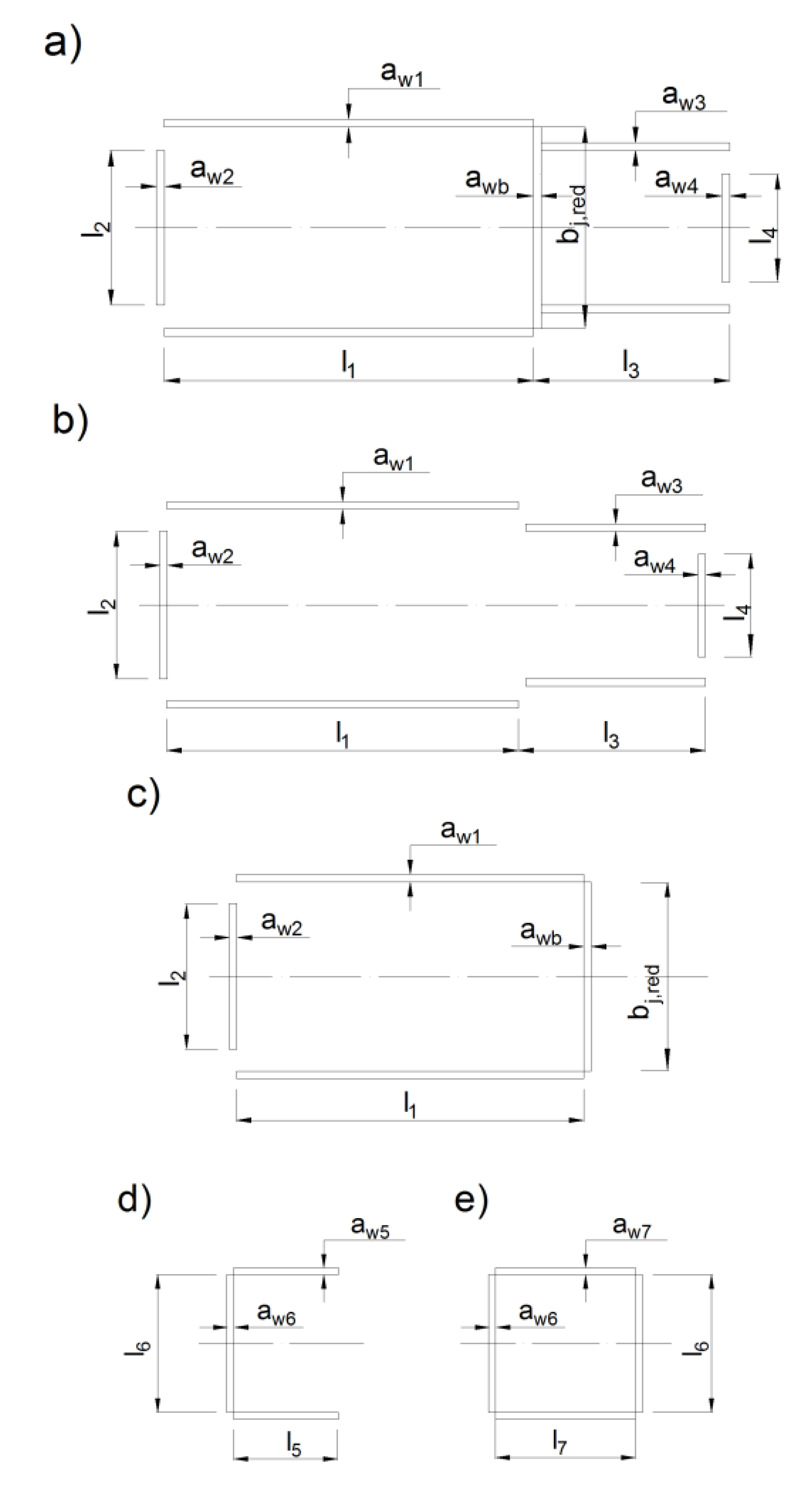
In Figure 1, using the IIW guidance [13] the layout of fillet welds in the K-type overlapped joint between the RHS braces and the H chord is shown. An assumption was made that the value of the component force perpendicular to the chord transferred directly through the welds connecting the brace members is equal to (Figure 1a):
Δ K i = α K i sin θ i   when   25 % λ o v 80 % , Δ K i = K i sin θ i   when   λ o v > 100 % ,
where α = q/p and 0.25 ≤ α ≤ 0.80, λ o v = ( q / p ) 100 % in %, q—the overlapping surface of braces projected on the face of the chord, p—length of contact area between the overlapping brace and the chord (the procedure of assessment of welds resistance in K-type joints made of hollow section is presented in [21]).
The remaining part of the load component perpendicular to the chord is
r e d Δ K j = K j sin θ j α K i sin θ i   when   25 %     λ o v     80 % , r e d Δ K j = K j sin θ j K i sin θ i   when   λ o v   >   100 % , r e d Δ K j = 0   in   the   case   of   no   external   load   applied   to   the   joint .
The values of effective lengths of welds are determined as follows (Figure 2):
1. In connections of braces with the flange of the chord (Figure 2a–c):
l 1 = h j / sin θ j ,   b j , r e d = b j 2 a w , l 2 = p j , e f f = t w + 2 r + 7 t f f y 0 / f y j ,   but   p j , e f f b j ,
l 3 = h i , r e d / sin θ i = ( 1 α ) h i / sin θ i , l 4 = p i , e f f = t w + 2 r + 7 t f f y 0 / f y i ,   but   p i , e f f b i .
2. In the direct connection between braces (Figure 2d,e):
  • In the case of the partial overlap:
    l 5 = q ( 1 + t g θ j / t g θ i ) cos θ j ,   l 6 = b i
  • In the case of the complete overlap:
    l 7 = h i / sin ( θ i + θ j ) , l 6 = b i
    where θi, θj—inclination angles of the overlapping and overlapped braces in relation to the chord, fy0 —the yield strength of the chord, bi, hi—respectively, the width and the height of the section of the overlapping brace, bj, hj—respectively, the width and the height of the section of the overlapped brace, ti—the wall thickness of the overlapping brace, tj—the wall thickness of the overlapped brace, tf—the flange thickness of the I-section, tw—the web thickness of I-section, r— the radius of the I-section.
Areas of cross-sections of effective lengths of welds are (Figure 1): A 1 = l 1 a w 1 , A 2 = l 2 a w 2 , A 3 = l 3 a w 3 , A 4 = l 4 a w 4 , A j , r e d = b j , r e d a w b , A 5 = l 5 a w 5 , A 6 = l 6 a w 6 , A 7 = l 7 a w 7 , where a w 1 , a w 2 , a w 3 , a w 4 a w b , a w 5 , a w 6 —thicknesses of welds.
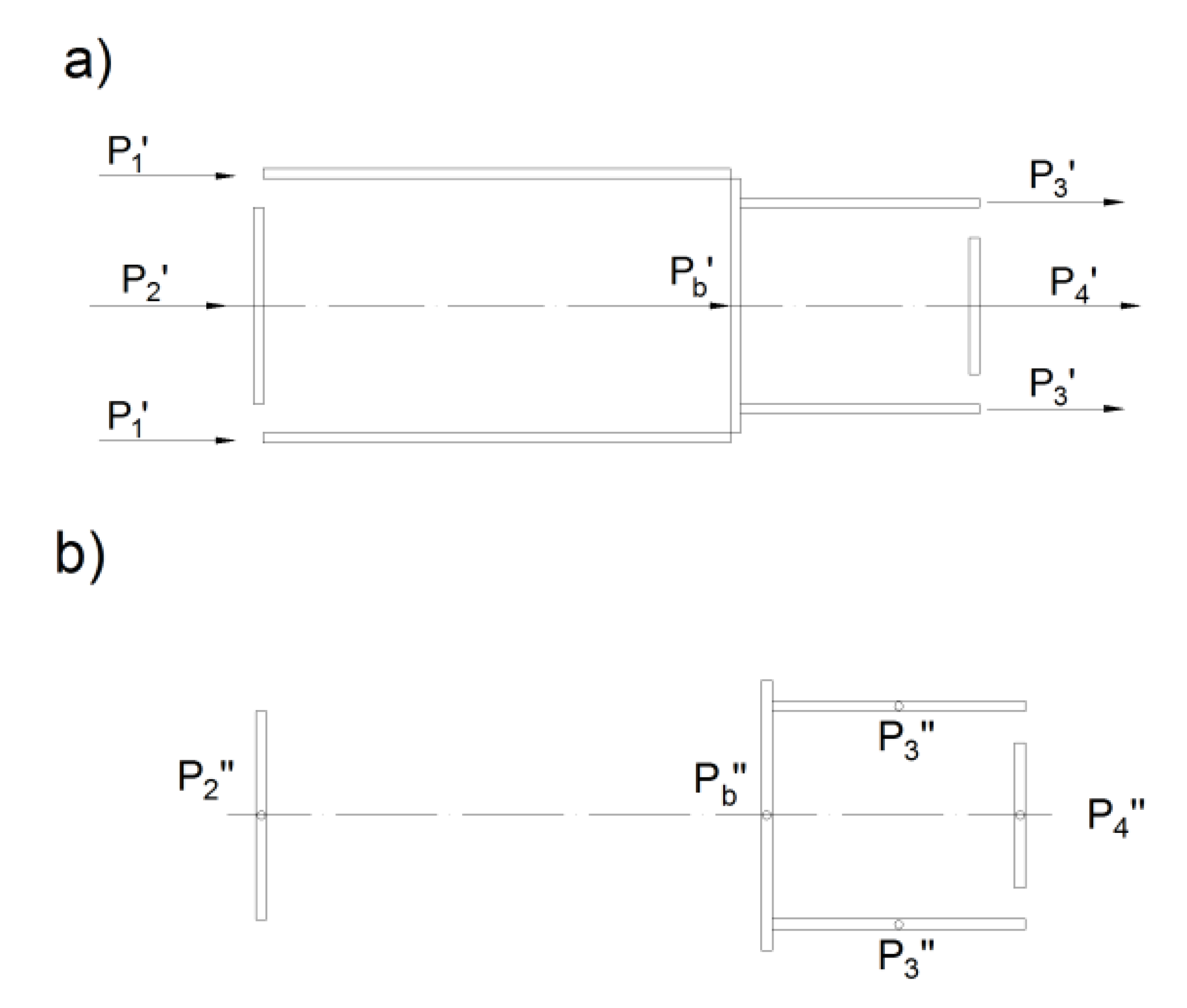
In the case of 25 % λ o v 80 % design situation, all welds are made (also in hidden part) in the place of the splice of braces with the chord. The sections of fillet welds are loaded by the component forces in braces parallel to the chord (Figure 3a).
Loads for individual effective lengths are
P 1 = ( K j cos θ j + K i cos θ i ) A 1 / A ,
P 2 = ( K j cos θ j + K i cos θ i ) A 2 / A ,
P 3 = ( K j cos θ j + K i cos θ i ) A 3 / A ,
P 4 = ( K j cos θ j + K i cos θ i ) A 4 / A ,
P b = ( K j cos θ j + K i cos θ i ) A j , r e d / A ,
where Kj and Ki are the designed axial loads acting respectively in overlapped and overlapping braces and
A = 2 A 1 + A 2 + 2 A 3 + A 4 + A j , r e d .
In the same design situation, the fillet weld sections are loaded by load components in braces perpendicular to the chord, as shown in Figure 3b. Forces loading effective lengths can be calculated based on equations:
P 1 = 0 ,
P 2 = r e d Δ K j A 2 / ( A 2 + A j , r e d ) ,
P 3 = ( 1 α ) Δ K i A 3 / ( 2 A 3 + A 4 ) ,
P 4 = ( 1 α ) Δ K i A 4 / ( 2 A 3 + A 4 ) ,
P b = r e d Δ K j A j , r e d / ( A 2 + A j , r e d ) ,
Components of loads in welds directly between the braces, in the case of the partial overlap are determined from equations (Figure 2d):
  • Loads parallel to the overlapped brace axis:
    P 5 = Δ K i A 5 sin θ j / ( 2 A 5 + A 6 ) ,
    P 6 = Δ K i A 6 sin θ j / ( 2 A 5 + A 6 ) .
  • Loads perpendicular to the overlapped brace axis:
    P 5 = Δ K i A 5 cos θ j / ( 2 A 5 + A 6 ) ,
    P 6 = Δ K i A 6 cos θ j / ( 2 A 5 + A 6 ) .
Components of loads in welds directly between the braces, in the case of the full overlap are determined from equations (Figure 2e):
  • Loads parallel to the overlapped brace axis:
    P 6 = Δ K i A 6 sin θ j / ( 2 A 6 + 2 A 7 ) ,
    P 7 = Δ K i A 7 sin θ j / ( 2 A 6 + 2 A 7 ) .
  • Loads perpendicular to the overlapped brace axis:
    P 6 = Δ K i A 6 cos θ j / ( 2 A 6 + 2 A 7 )
    P 7 = Δ K j A 7 cos θ j / ( 2 A 6 + 2 A 7 ) .
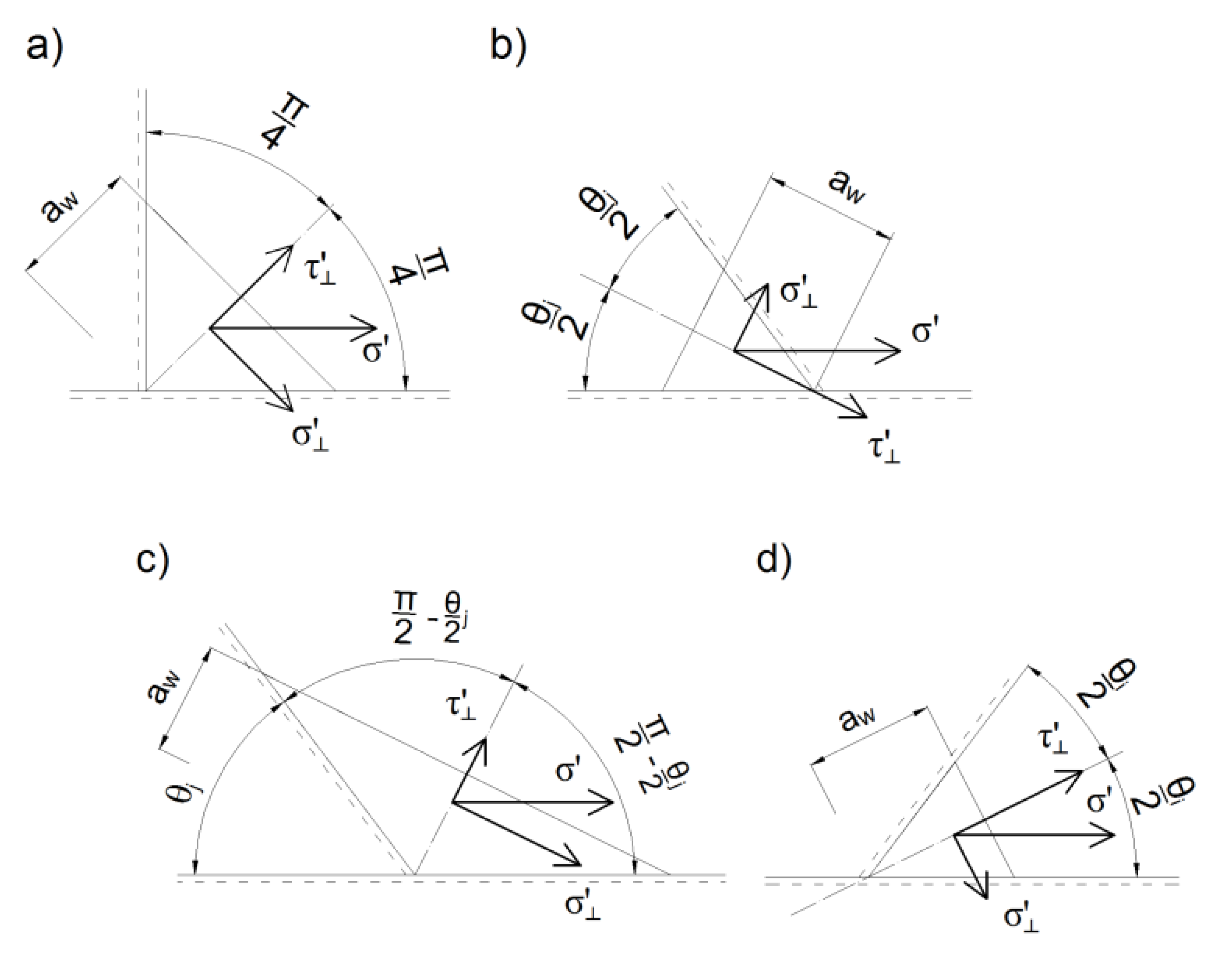
Stresses in welds caused by the force parallel to the chord at the partial overlap of 25 % λ o v 80 % :
1. In longitudinal welds (Figure 4a):
  • In the case of welds placed by the overlapped brace’s walls:
    σ = 0 ,     σ = τ = 0 ,   τ I I = P 1 / ( a w 1 l 1 )
  • In the case of welds placed by the overlapping brace’s walls:
    σ = 0 ,     σ = τ = 0 ,   τ I I = P 3 / ( a w 3 l 3 )
2. On the not fully cooperating overlapped brace’s transverse length (Figure 4b):
σ = P 2 / ( a w 2 l 2 ) ,   σ = σ sin ( θ j / 2 ) , τ = σ cos ( θ j / 2 ) ,   τ I I = 0 .
3. On the fully cooperating transverse length of the overlapped brace (Figure 4c):
σ = P b / ( a w b b j , r e d ) ,   σ = σ cos ( θ j / 2 ) , τ = σ sin ( θ j / 2 ) ,   τ I I = 0 .
4. On the not fully cooperating overlapping brace ‘s transverse length (Figure 4d):
σ = P 4 / ( a w 4 l 4 ) ,   σ = σ sin ( θ i / 2 ) , τ = σ cos ( θ i / 2 ) ,   τ I I = 0 .
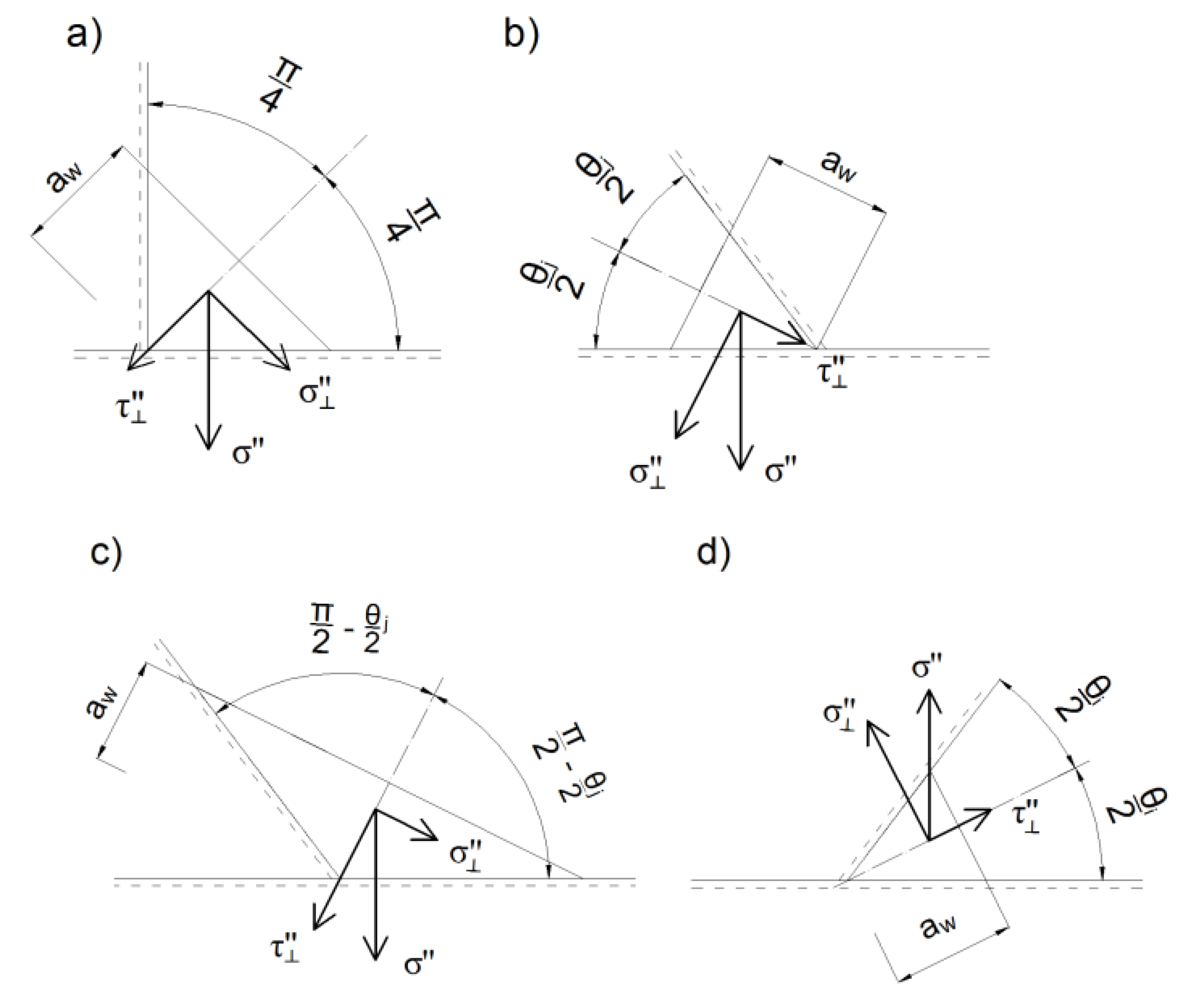
Stresses in welds of load perpendicular to the chord at the partial overlap of 25 % λ o v 80 % :
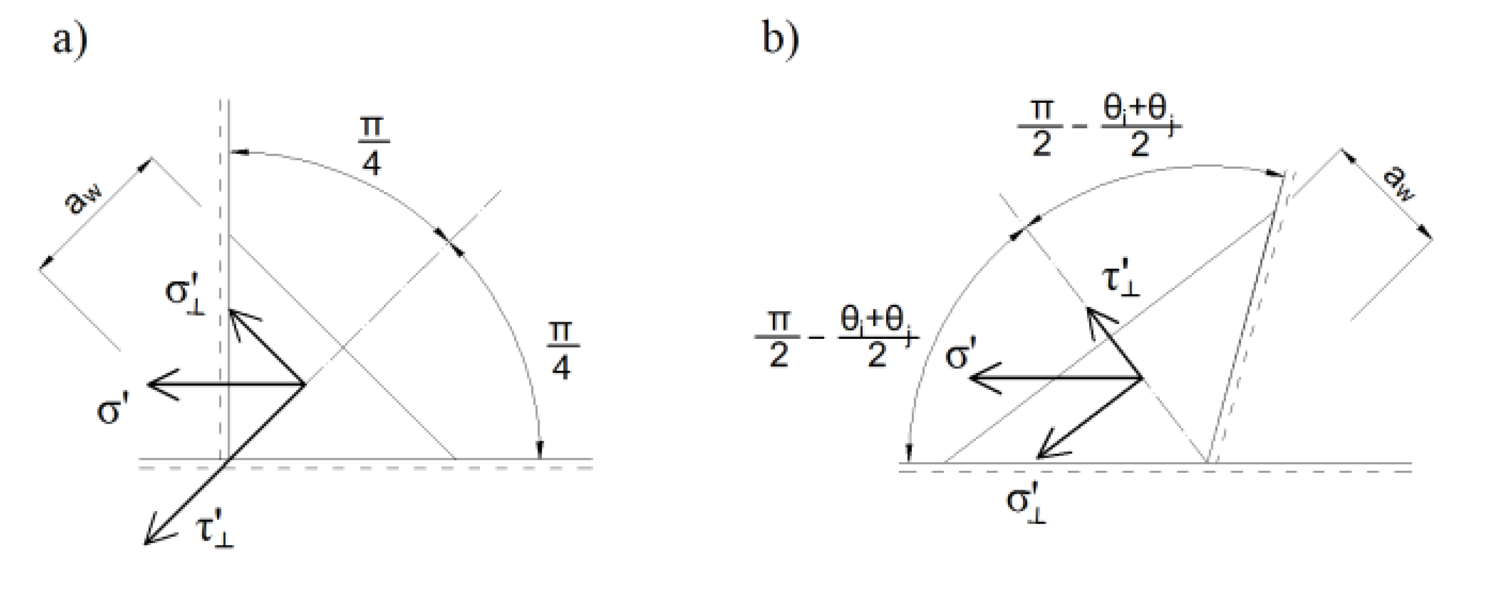
1. In longitudinal welds (Figure 5a):
  • In the case of welds placed by the walls of the overlapped brace:
    σ = P 1 a w 1 l 1 ,   σ = σ 2 , τ = σ 2 , τ I I = 0 .
  • I the case of welds placed by the walls of the overlapping brace:
    σ = P 3 a w 3 l 3 ,   σ = σ 2 , τ = σ 2 ,   τ I I = 0 .
2. On the not fully cooperating the overlapped brace‘s transverse weld (Figure 5b):
σ = P 2 a w 2 l 2 ,   σ = σ cos θ j 2 , τ = σ sin θ j 2 ,   τ I I = 0 .
3. On the fully cooperating the overlapped brace’s transverse weld (Figure 5c):
σ = P b a w b b j , r e d ,   σ = σ cos θ j 2 , τ = σ sin θ j 2 ,   τ I I = 0 .
4. On the not fully cooperating the overlapping brace’s transverse weld (Figure 5d):
σ = P 4 a w 4 l 4 ,   σ = σ cos θ i 2 , τ = σ sin θ i 2 ,   τ I I = 0 .
Stresses in the welds made directly between the brace members at the partial overlap of 25% ≤ λov ≤ 80% from the force parallel to the overlapped brace axis:
1. In longitudinal welds (Figure 6a):
σ = 0 ,   σ = τ = 0 ,   τ I I = P 5 a w 5 l 5 .
2. In the fully cooperating transverse weld (Figure 6b):
σ = P 6 a w 6 l 6 ,   σ = σ cos θ i + θ j 2 , τ = σ sin θ i + θ j 2 ,   τ I I = 0 .
Stresses in welds placed between the brace members at the partial overlap of 25% ≤ λov ≤ 80% from the force perpendicular to the overlapped brace:
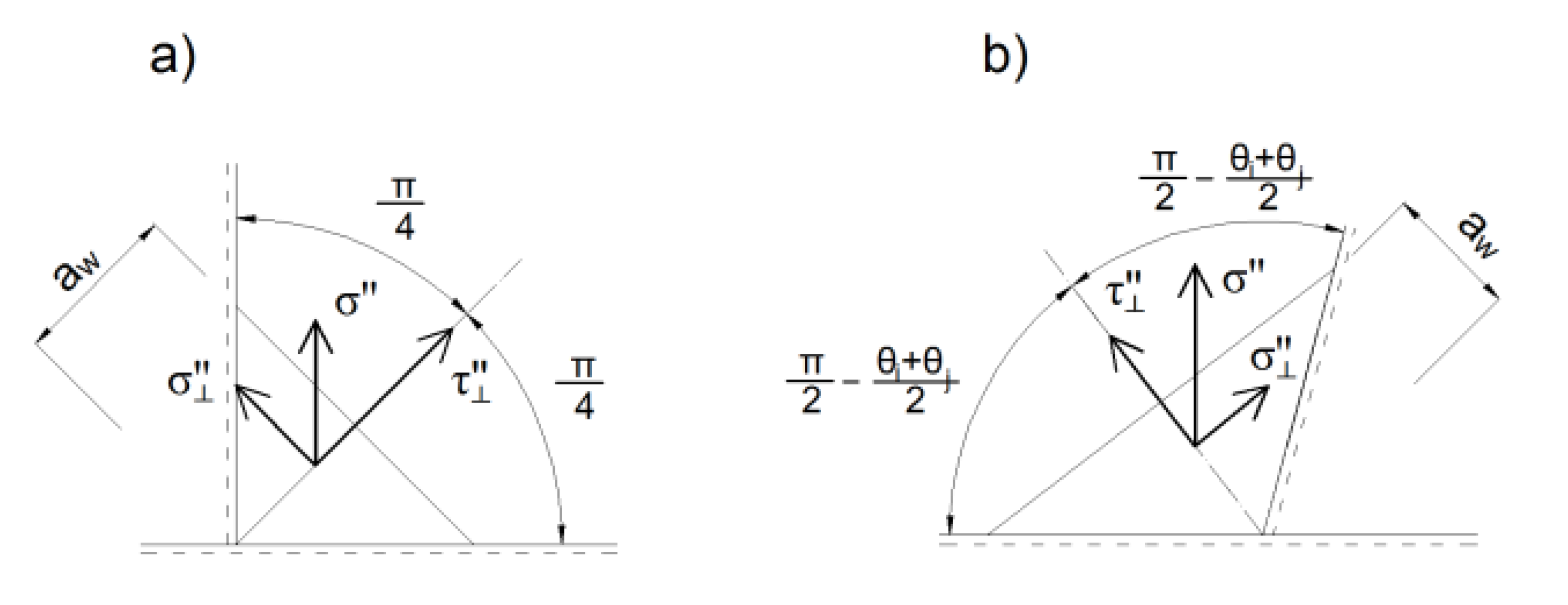
1. In longitudinal welds (Figure 7a):
σ = P 5 a w 5 l 5 ,   σ = σ 2 , τ = σ 2 , τ I I = 0 .
2. In the fully cooperating transverse weld (Figure 7b):
σ = P 6 a w 6 l 6 ,   σ = σ cos θ j + θ i 2 , τ = σ sin θ j + θ i 2 ,   τ I I = 0 .
The procedure of checking of a design situation with the full overlap of braces λov = 100% is analogous. In that case, the stresses in the transverse weld located near the connection of the overlapped brace with the chord should be examined (Figure 8), using the loads expressed by the Equations (24) and (25). The components of stress are:
1. In the transverse weld from the force parallel to the overlapped brace (Figure 8a):
σ = P 6 a w 6 l 6 ,   σ = σ sin θ j + θ i 2 , τ = σ cos θ j + θ i 2 , τ I I = 0 .
2. In the transverse weld from the force perpendicular to the overlapped brace (Figure 8b):
σ = P 6 a w 6 l 6 ,   σ = σ cos θ j + θ i 2 , τ = σ sin θ j + θ i 2 ,   τ I I = 0 .
The component stresses occurring in cross-section of the welds should be added using the formulas:
τ I I = τ I I + τ I I ;   σ = σ + σ ;   τ = τ + τ .
Standardized formulas for checking the safety of fully or partially cooperating transverse and longitudinal welds are:
[ σ 2 + 3 ( τ 2 + τ I I 2 ) ] f u / ( β w γ M 2 ) ,
σ 0.9 f u / γ M 2 ,
where: βw—the correlation coefficient, fu—the tensile strength of steel, γM2 = 1.25—the safety factor.

3. Conclusions

RHS joints are generally semi-rigid, mainly because of the preferred technologies for their production, i.e., the direct welding of members. It implements a significant load from braces to the relatively slender front walls of the chord. The basic information for calculating joint resistance is given in many standards and references, but European standards contain a general recommendation on the calculation of capacity of welded joints and do not provide detailed design guidelines. The information contained is random and concerns only Y, X, K, and N joints with the gap. Additionally, in the case of the K and N types of joints with partially overlapped brace members, there is no indication of how to calculate the capacity of welds between the members.
This paper presents the method of assessment of the welded K and N type overlapped joints between RHS brace members and I or H section chords. This method comprises determining the stress components in welds in different load cases based on their effective lengths.
Design Example:
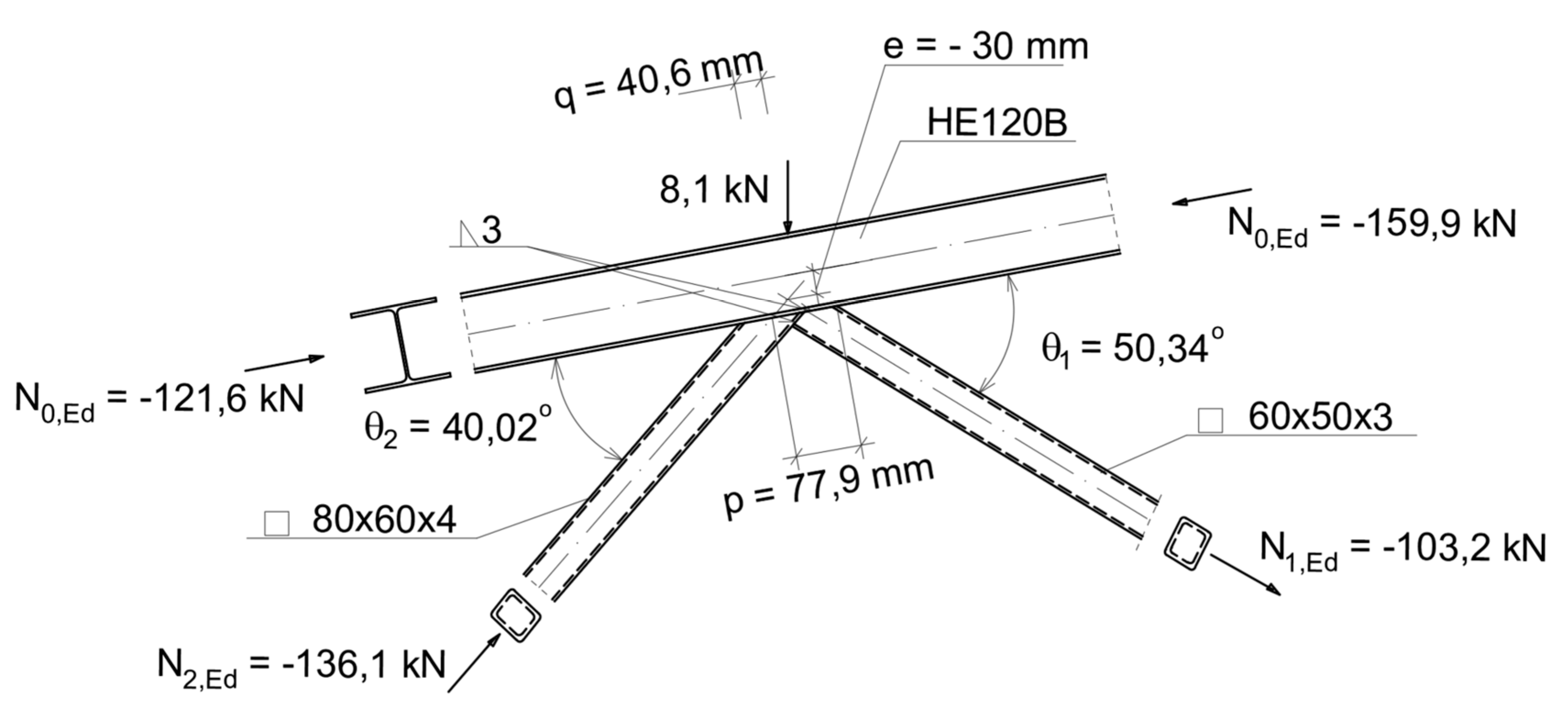
Check the resistance of welds of an overlap K joint with a chord made of HEB 120 and SHS braces (Figure 9). Steel grade of S355H, fy = 355 N/mm2, fu = 490 N/mm2. Chord: h0 = 120 mm, bf = 120 mm, tw = 6.5 mm, tf = 11.0 mm, r = 12.0 mm, A0 = 34.0 cm2, Wpl.y,0 = 165.2 cm3, N0 = −159.9 kN. Brace loaded with compressive force: h2 = 80 mm, b2 = 60 mm, t2 = 4 mm; N2.Ed = −136.1 kN. Brace loaded with tension force: h1 = 60 mm, b1 = 50 mm, t1 = 3 mm, N1.Ed = + 103.2 kN. The angles: θ1 = 50.34° > 30°, θ2 = 40.02° > 30° (sin θ1 = 0.7698, cos θ1 = 0.6382, sin θ2 = 0.6431, cos θ2 = 0.7658, sin (θ1 + θ2)≅ 1.0). The overlapped transverse weld is done −cs = 2.
A. An Overlap Value.
e = −30 mm,
q = ( e + h 0 2 ) sin ( θ 1 + θ 2 ) sin θ 1 sin θ 2 h 1 2 sin θ 1 h 2 2 sin θ 2 = ( 30 + 120 2 ) 1.0 0.7698 0.6431 60 2 0.7698 80 2 0.6431 = 40.6   mm ,
p = h 1 / sin θ 1 = 60 / 0.7698 = 77.9   mm ,
λ 0 v = ( q / p ) 100 % = ( 40.6 / 77.9 ) 100 % = 52.1   %   <   λ 0 v , lim = 80 % .
B. The Design Conditions.
h 1 t 1 = 60 3 = 20.0   <   35 ,   b 1 t 1 = 50 3 = 16.7   <   35 ,   h 2 t 2 = 80 4 = 20.0   <   35 ,
b 2 t 2 = 60 4 = 15.0   <   35 ,
h 1 b 1 = 60 50 = 1.2 > 1.0 ,   h 2 b 2 = 80 60 = 1.33 > 1.0 .
C. The Design Resistance of the Joint.
In the case of 50% < λ 0 v = 52.1% < 80%:
p 1 , e f f = t w + 2 r + 7 t f f y 0 / f y 1 = 6.5 + 2 12 + 7 11 355 / 355 = 107.5 mm > b 1 = 50   mm
Adopted p 1 , e f f = 50   mm .
b e , o v = 10 b j / t j f y j t j f y i t i b i = 10 60 / 4 355 4 355 3 50 = 44.4   mm   < b 1 = 50   mm .
The brace failure.
N 1 , R d = f y 1 t 1 ( p 1 , e f f + b e , o v + h 1 2 t 1 ) / γ M 5 = 355 3 ( 50 + 44.4 + 60 2 3 ) / 1.0 = 158000   N = 158.0   kN ,
N 2 , R d = N 1 , R d sin θ 1 sin θ 2 = 158.0 0.7698 0.6431 = 189.1   kN .
Checking the braces resistance.
103.2 158 = 0.65 <   1.0 ,   136.1 189.1 = 0.72 <   1.0 .
The brace bending and the axial force resistance.
M 0 = ± 0.5 ( N 02. E d N 01. E d ) e = ± 0.5   ( 159.9 + 121.6 ) 30 = ± 574.5 kNmm ,
M 0. p l = W p l .0 f y / γ M 1 = 165.2 10 3 355 / 1.0 = 586.5 · 10 2 kNmm ,
N 0. p l = A 0 f y / γ M 1 = 34.0 10 2 355 / 1.0 = 1207 10 3   N = 1207   kN , N 0 N 0 . p l + M 0 M 0. p l = 159.9 1207 + 574.5 58650 = 0.14 < 1.0.
D. The Shear Resistance of Thin Fillet Welds.
Effective parts of welds, ( α = p q = 0.521 ) :
l 1 = h 2 / sin θ 2 = 80 / 0.6431 = 124.4   mm , l 2 = p 2 , e f f = t w + 2 r + 7 t f f y 0 / f y 2 = 6.5 + 2 12 + 7 11 355 / 355 = 107.5 mm > b 2 = 60 mm
Assumed l2=60 mm.
b j . r e d = b 2 2 a w = 60 2 3 = 54   mm , l 3 = h i . r e d / sin θ i = ( 1 α ) h i / sin θ i = ( 1 0.521 ) 60 / 0.7698 = 37.3   mm , l 4 = p 1. e f f = t w + 2 r + 7 t f f y 0 / f y 1 = = 107.5   mm   > b 1 = 50   mm .
Assumed   l 4 = 50   mm . l 5 = q ( 1 + tan θ 2 / tan θ 1 ) cos θ 2 = 40.6 ( 1 + 0.8397 / 1.2062 ) 0.7658 = 31.3   mm ,
l 6 = b 1 = 50 mm .
Cross-section areas of effective lengths of welds.
Assumed the thickness of welds a w 1 = a w 2 = a w 3 = a w b = a w 4 = a w 5 = a w 6 = 3.0 mm,
A 1 = l 1 a w 1 = 124.4 3 = 373.2   mm 2 , A 2 = l 2 a w 2 = 60 3 = 180.0   mm 2 ,
A 3 = l 3 a w 3 = 37.3 3 = 111.9   mm 2 , A 2 , r e d = b 2 , r e d a w b = 54 3 = 162.0   mm 2 ,
A 4 = l 4 a w 4 = 50 3 = 150.0   mm 2 , A 5 = l 5 a w 5 = 31.3 3 = 93.9   mm 2 ,
A 6 = l 6 a w 6 = 50 3 = 150.0   mm 2 ,
A = 2 A 1 + A 2 + 2 A 3 + A j , r e d + A 4 = 2 373.2 + 180 + 2 111.9 + 162 + 150 = 1462.2   mm 2 .
Forces acting on individual weld’s sections (K1 = N1.Ed ; K2 = N2.Ed):
Δ K 1 = α K 1 sin θ 1 = 0.521 103.2 0.7698 = 41.4   kN ,
r e d Δ K 2 = K 2 sin θ 2 α K 1 sin θ 1 = 136.1 0.6431 0.521 103.2 0.7698 = 46.1   kN .
Loads in effective lengths parallel to the chord.
P 1 = ( K 2 cos θ 2 + K 1 cos θ 1 ) A 1 / A = ( 136.1 0.7658 + 103.2 0.6382 ) 373.2 / 1462.2 = 43.4   kN ,
P 2 = ( K 2 cos θ 2 + K 1 cos θ 1 ) A 2 / A = ( 136.1 0.7658 + 103.2 0.6382 ) 180.0 / 1462.2 = 20.9   kN ,
P 3 = ( K 2 cos θ 2 + K 1 cos θ 1 ) A 3 / A = ( 136.1 0.7658 + 103.2 0.6382 ) 111.9 / 1462.2 = 13.0   kN ,
P 4 = ( K 2 cos θ 2 + K 1 cos θ 1 ) A 4 / A = ( 136.1 0.7658 + 103.2 0.6382 ) 150.0 / 1462.2 = 17.4 kN ,
P b = ( K 2 cos θ 2 + K 1 cos θ 1 ) A j , r e d / A = ( 136.1 0.7658 + 103.2 0.6382 ) 162 / 1462.2 = 18.8 kN ,
P 5 = Δ K 1 A 5 sin θ 2 / ( 2 A 5 + A 6 ) = 41.4 93.9 0.6431 / ( 2 93.9 + 150 ) = 7.4 kN ,
P 6 = Δ K 1 A 6 sin θ 2 / ( 2 A 5 + A 6 ) = 41.4 150 0.6431 / ( 2 93.9 + 150 ) = 11.8 kN .
Loads in effective lengths perpendicular to the chord.
P 1 = 0 ,
P 2 = r e d Δ K 2 A 2 / ( A 2 + A 2 , r e d ) = 46.1 180 / ( 180 + 162 ) = 24.3   kN ,
P 3 = ( 1 α ) Δ K 1 A 3 / ( 2 A 3 + A 4 ) = ( 1 0.521 ) 41.4 111.9 / ( 2 111.9 + 150 ) = 5.9   kN ,
P 4 = ( 1 α ) Δ K 1 A 4 / ( 2 A 3 + A 4 ) = ( 1 0.521 ) 41.4 150 / ( 2 111.9 + 150 ) = 8.0   kN ,
P b = r e d Δ K 2 A 2 , r e d / ( A 2 + A 2 , r e d ) = 46.1 162 / ( 180 + 162 ) = 21.8   kN ,
P 5 = Δ K 1 A 5 cos θ 2 / ( 2 A 5 + A 6 ) = 41.4 93.9 0.7658 / ( 2 93.9 + 150 ) = 8.8   kN ,
P 6 = Δ K 1 A 6 cos θ 2 / ( 2 A 5 + A 6 ) = 41.4 150 0.7658 / ( 2 93.9 + 150 ) = 14.1   kN .
Stresses on the throat section of a fillet welds from the force component parallel to the chord:
-
longitudinal welds between the lower (overlapped) brace and the chord:
σ = 0 ,
σ = τ = 0 ,
τ I I = P 1 a w 1 l 1 = 43.4 10 3 3.0 124.4 = 116.3   MPa ,
-
the not fully effective transverse weld between the lower brace and the chord:
σ = P 2 a w 2 l 2 = 20.9 10 3 3.0 60 = 116.1   MPa ,
σ = σ sin θ 2 2 = 116.1 0.3422 = 39.7   MPa ,
τ = σ cos θ 2 2 = 116.1 0.9396 = 109.1   MPa ,
τ I I = 0 ,
-
longitudinal welds between the upper (overlapping) brace and the chord:
σ = 0 ,
σ = τ = 0 ,
τ I I = P 3 a w 3 l 3 = 13.0 10 3 3.0 37.3 = 116.2   MPa ,
-
the fully effective transverse weld between the lower brace and the chord:
σ = P b a w b b j . r e d = 18.8 10 3 3.0 54 = 116.0   MPa ,
σ = σ cos θ 2 2 = 116.0 0.9396 = 109.0   MPa ,
τ = σ sin θ 2 2 = 116.0 0.3422 = 39.7   MPa ,
τ I I = 0 ,
-
the not fully effective transverse weld between the upper brace and the chord:
σ = P 4 a w 4 l 4 = 17.4 10 3 3.0 50 = 116.0   MPa ,
σ = σ sin θ 1 2 = 116.0 0.3849 = 44.6   MPa ,
τ = σ cos θ 1 2 = 116.0 0.9050 = 105.0   MPa ,
τ I I = 0 ,
-
longitudinal welds between the upper (overlapping) brace and the lower (overlapped) brace:
σ = 0 ,
σ = τ = 0 ,
τ I I = P 5 a w 5 l 5 = 7.4 10 3 3.0 31.3 = 78.8   MPa ,
-
the transverse weld between the upper brace and the lower brace:
σ = P 6 a w 6 l 6 = 11.8 10 3 3.0 50 = 78.7   MPa ,
σ = σ cos θ 1 + θ 2 2 = 78.7 0.7049 = 55.5   MPa ,
78.8 0.7093 = 55.9   MPa ,
τ I I = 0
.
Stresses on the throat section of a fillet welds from the force component perpendicular to the chord:
-
longitudinal welds between the lower (overlapped) brace and the chord:
P 1 = 0 ,
σ = τ = 0 ,
τ I I = 0 ,
-
the not fully effective transverse weld between the lower brace and the chord:
σ = P 2 a w 2 l 2 = 24.3 10 3 3.0 60.0 = 135.0   MPa ,
σ = σ cos θ 2 2 = 135.0 0.9396 = 126.8   MPa ,
τ = σ sin θ 2 2 = 135.0 0.3422 = 46.2   MPa ,
τ I I = 0 ,
-
longitudinal welds between the upper (overlapping) brace and the chord:
σ = P 3 a w 3 l 3 = 5.9 10 3 3 37.3 = 52.7   MPa ,
σ = σ 2 = 52.7 2 = 37.2   MPa ,
τ = σ 2 = 52.7 2 = 37.2   MPa ,
τ I I = 0 ,
-
the fully effective transverse weld between the lower brace and the chord:
σ = P b a w b b j . r e d = 21.8 10 3 3.0 54 = 134.6   MPa ,
σ = σ cos θ 2 2 = 134.6 0.9396 = 126.4   MPa ,
τ = σ sin θ 2 2 = 134.6 0.3422 = 46.1   MPa ,
τ I I = 0 ,
-
the not fully effective transverse weld between the upper brace and the chord:
σ = P 4 a w 4 l 4 = 8.0 10 3 3.0 50 = 53.3   MPa ,
σ = σ cos θ 1 2 = 53.3 0.9050 = 48.3   MPa ,
τ = σ sin θ 1 2 = 53.3 0.3849 = 20.5   MPa ,
τ I I = 0 ,
-
longitudinal welds between the upper brace and the lower brace:
σ = P 5 a w 5 l 5 = 8.8 10 3 3.0 31.3 = 93.7   MPa ,
σ = σ 2 = 93.7 2 = 66.3   MPa ,
τ = σ 2 = 93.7 2 = 66.3   MPa ,
τ I I = 0 ,
-
the transverse weld between the upper brace and the lower brace:
σ = P 6 a w 6 l 6 = 14.1 10 3 3.0 50 = 94.0   MPa ,
σ = σ cos θ 1 + θ 2 2 = 94 0.7049 = 66.3   MPa ,
τ = σ sin θ 1 + θ 2 2 = 94 0.7093 = 66.7   MPa ,
τ I I = 0
.
The normal and shear stresses in welds.
-
longitudinal welds between the lower brace and the chord:
τ | | = τ | | + τ | | = 116.3 + 0 = 116.3   MPa ,
σ = σ + σ = 0 + 0 = 0   MPa ,
τ = τ + τ = 0 0 = 0   MPa ,
-
the not fully effective transverse weld between the lower brace and the chord:
τ | | = τ | | + τ | | = 0 + 0 = 0 ,
σ = σ + σ = 39.7 126.8 = 87.1   MPa ,
τ = τ + τ = 109.1 + 46.2 = 155.3   MPa ,
-
longitudinal welds between the upper brace and the chord:
τ | | = τ | | + τ | | = 116.2 + 0 = 116.2   MPa ,
σ = σ + σ = 0 37.2 = 37.2   MPa ,
τ = τ + τ = 0 + 37.2 = 37.2   MPa ,
-
the fully effective transverse weld between the lower brace and the chord:
τ | | = τ | | + τ | | = 0 + 0 = 0 ,
σ = σ + σ = 109.0 + 126.4 = 235.4   MPa ,
τ = τ + τ = 39.7 + 46.1 = 85.8   MPa ,
-
the not fully effective transverse weld between the upper brace and the chord:
τ | | = τ | | + τ | | = 0 + 0 = 0   MPa ,
σ = σ + σ = 44.6 48.3 = 3.7   MPa ,
τ = τ + τ = 105.0 + 20.5 = 125.5   MPa ,
-
longitudinal welds between the upper brace and the lower brace:
τ | | = τ | | + τ | | = 78.8 + 0 = 78.8   MPa ,
σ = σ + σ = 0 66.3 = 66.3   MPa ,
τ = τ + τ = 0 + 66.3 = 66.3   MPa ,
-
the transverse weld between the upper brace and the lower brace:
τ | | = τ | | + τ | | = 0 + 0 = 0   MPa ,
σ = σ + σ = 55.5 + 66.3 = 121.8   MPa ,
τ = τ + τ = 55.9 66.7 = 10.8   MPa .
E. The design resistance of the fillet welds.
-
longitudinal welds between the lower brace and the chord:
[ σ 2 + 3 ( τ 2 + τ | | 2 ) ] 0.5 = [ 0 2 + 3 ( 0 2 + 116.3 2 ) ] 0.5 = 201.4   MPa < f u β w γ M w = 490 0.9 1.25 = 435.6   MPa ,
σ = 0   MPa   <   0.9 490 1.25 = 352.8   MPa ,
-
the not fully effective transverse weld between the lower brace and the chord:
[ σ 2 + 3 ( τ 2 + τ | | 2 ) ] 0.5 = [ ( 87.1 ) 2 + 3 ( 155.3 2 + 0 2 ) ] 0.5 = 282.7   MPa < f u β w γ M w = 490 0.9 1.25 = 435.6   MPa ,
σ = 87.1   MPa   <   0.9 490 1.25 = 352.8   MPa ,
-
longitudinal welds between the upper brace and the chord:
[ σ 2 + 3 ( τ 2 + τ | | 2 ) ] 0.5 = [ ( 37.2 ) 2 + 3 ( 37.2 2 + 116.2 2 ) ] 0.5 = 247.6   MPa < f u β w γ M w = 490 0.9 1.25 = 435.6   MPa ,
σ = 72.1   MPa <   0.9 490 1.25 = 352.8   MPa ,
-
the fully effective transverse weld between the lower brace and the chord:
[ σ 2 + 3 ( τ 2 + τ | | 2 ) ] 0.5 = [ 235.4 2 + 3 ( 85.8 2 + 0 ) ] 0.5 = 278.4   MPa   <   f u β w γ M w = 490 0.9 1.25 = 435.6   MPa , σ = 235.4   MPa   <   0.9 490 1.25 = 352.8   MPa ,
-
the not fully effective transverse weld between the upper brace and the chord:
[ σ 2 + 3 ( τ 2 + τ | | 2 ) ] 0.5 = [ ( 3.7 ) 2 + 3 ( 125.5 2 + 0 2 ) ] 0.5 = 217.4   MPa < f u β w γ M w = 490 0.9 1.25 = 435.6   MPa ,
σ =   3.7   MPa < 0.9 490 1.25 = 352.8   MPa ,
-
longitudinal welds between the upper brace and the lower brace:
[ σ 2 + 3 ( τ 2 + τ | | 2 ) ] 0.5 = [ ( 66.3 ) 2 + 3 ( 66.3 2 + 78.8 2 ) ] 0.5 = 190.3 MPa < f u β w γ M w = 490 0.9 1.25 = 435.6   MPa ,
σ = 66.3   MPa < 0.9 490 1.25 = 352.8   MPa ,
-
the transverse weld between the upper brace and the lower brace:
[ σ 2 + 3 ( τ 2 + τ | | 2 ) ] 0.5 = [ 121.8 2 + 3 ( ( 10.8 ) 2 + 0 2 ) ] 0.5 = 123.2   MPa < f u β w γ M w = 490 0.9 1.25 = 435.6   MPa ,
σ = 121.8   MPa < 0.9 490 1.25 = 352.8   MPa .
The safety coefficient is equal: 435.6 282.7 435.6 100 % = 35.1 % .

Author Contributions

Conceptualization, M.B.; methodology, M.B. and F.B.; analysis, M.B. and F.B; writing, M.B. and F.B. All authors have read and agreed to the published version of the manuscript.

Funding

This research was funded by grants numbers: S/WBiIŚ/2/2017; W/WBiIŚ/12/2019.

Conflicts of Interest

The authors declare no conflict of interest.

References

  1. Eekhout, M. Tubular Structures in Architecture, 2nd ed.; Delft University of Technology: Delft, The Netherlands, 2011; 127p. [Google Scholar]
  2. Wardenier, J.; Packer, J.A.; Zhao, X.L.; Van der Vegte, G.J. Hollow Sections in Structural Applications; John Wiley & Sons: Hoboken, NJ, USA, 2010; 232p. [Google Scholar]
  3. Brodka, J.; Broniewicz, M. Steel Structures from Hollow Sections; Arkady: Warsaw, Poland, 2001; 383p. [Google Scholar]
  4. Dutta, D. Structures with Hollow Sections, 1st ed.; Ernst & Sohn: Berlin, Germany, 2002; 600p. [Google Scholar]
  5. Packer, J.A.; Wardenier, J. Design rules for welds in RHS K, T, Y and X connections. In Proceedings of the IIW International Conference on Engineering Design in Welded Constructions, Madrid, Spain, 7–8 September 1992; pp. 113–120. [Google Scholar]
  6. Frater, G.S.; Packer, J.A. Weldment design for RHS truss connections. I: Applications. J. Struct. Eng. 1992, 118, 2784–2803. [Google Scholar] [CrossRef]
  7. Frater, G.S.; Packer, J.A. Weldment design for RHS truss connections. II: Experimentation. J. Struct. Eng. 1992, 118, 2804–2820. [Google Scholar] [CrossRef]
  8. Teh, L.H.; Rasmussen, K.J.R. Strength of Butt Welded Connections between Equal Width Rectangular Hollow Sections; Research Report No. R817; Department of Civil Engineering, University of Sydney: Sydney, Australia, 2002; 27p. [Google Scholar]
  9. Packer, J.A.; Henderson, J.E. Hollow Structural Section Connections and Truss—A Design Guide, 2nd ed.; Canadian Institute of Steel Construction: Toronto, ON, Canada, 1997; 447p. [Google Scholar]
  10. Packer, J.A.; Sherman, D.R.; Lecce, M. HSS Connections. Steel Design Guide No. 24; American Institute of Steel Construction: Chicago, IL, USA, 2009; 146p. [Google Scholar]
  11. IIW. Recommendations for Fatigue Design of Welded Joints and Components; Commission XV. IIW Docs, IIW-1823-07; International Institute of Welding: Paris, France, 1823. [Google Scholar]
  12. ISO 14346. Static Design Procedure for Welded Hollow Section Joints—Recommendations; International Institute of Welding: Paris, France, 2013. [Google Scholar]
  13. IIW. Static Design Procedure for Welded Hollow Section Joints—Recommendations, 3rd ed.; Commission XV. IIW Doc. XV-1329-09; International Institute of Welding: Paris, France, 2009. [Google Scholar]
  14. Packer, J.A.; Wardenier, J.; Zhao, X.L.; Van der Vegte, G.J.; Kurobane, Y. Design Guide for Rectangular Hollow Section (RHS) Joints under Predominantly Static Loading; LSS Verlag, CIDECT: Koln, Germany, 2009; pp. 149p. [Google Scholar]
  15. Brodka, J.; Broniewicz, M. Design of welded joints of trusses made of hollow sections. In Steel Construction; No 1; Polish Chamber of Steelwork: Warsaw, Poland, 2002; p. 29. [Google Scholar]
  16. Brodka, J.; Broniewicz, M. Assessing of resistance of connections according to EN 1993-1-8:2006. In Steel Construction; No 1; Polish Chamber of Steelwork: Warsaw, Poland, 2007; pp. 32–38. [Google Scholar]
  17. Brodka, J.; Broniewicz, M. Calculation of welding trusses overlap joints. In Archives of Civil Engineering; Committee for Civil Engineering, Polish Academy of Sciences: Warsaw, Poland, 2013; 24p. [Google Scholar]
  18. Davies, G.; Crockett, P. Effect of the hidden weld on RHS partial overlap K joint capacity. In Proceedings of the 6th International Symposium on Tubular Structures, Melbourne, Australia, 14–16 December 1994; Balkema: Rotterdam, The Netherlands, 1994; pp. 573–579. [Google Scholar]
  19. Dexter, E.M.; Lee, M.M.K. Effect of overlap on the behaviour of axially loaded CHS K-joints. In Proceedings of the 8th International Symposium on Tubular Structures, Singapore, 26–28 August 1998; Balkema: Rotterdam, The Netherlands, 1998; pp. 249–258. [Google Scholar]
  20. EN 1993-1-8. Eurocode 3: Design of Steel Structures. Part 1–8: Design of Joints; European Committee For Standardization: Brussels, Belgium, 2006. [Google Scholar]
  21. Brodka, J.; Broniewicz, M. Calculation of welding trusses overlap joints made of rectangular hollow sections. Arch. Civ. Eng. 2013, 59, 441–468. [Google Scholar] [CrossRef] [Green Version]
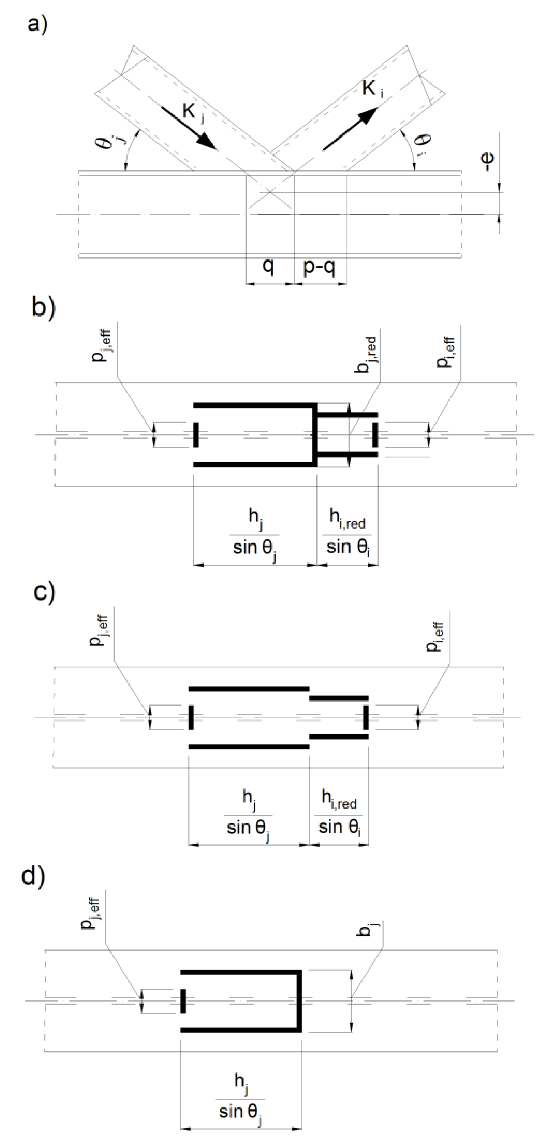
Figure 1. The connection of hollow section brace members to I- or H-section chords: (a) The standard joint: (b) The layout of fillet welds joining the rectangular hollow section (RHS) braces to the H chords when 25 % λ o v 80 % and the hidden part of the connection is welded; (c) the layout of fillet welds joining the RHS braces to the H chords when 25 % λ o v 80 % and the hidden part of the connection does not have to be welded; (d) layout of fillet welds joining the RHS braces to the H chords when λ o v > 100 % .
Buildings 10 00043 g001
Figure 2. Effective lengths of welds: (a) the layout of fillet welds joining the RHS braces to the H chords when 25 % λ o v 80 % and the hidden part of the connection is welded; (b) the layout of fillet welds joining the RHS braces to the H chords when 25 % λ o v 80 % and the hidden part of the connection is not welded; (c) the layout of fillet welds joining the RHS braces to the H chords when λ o v > 100 % ; (d) welds between the braces in the case of the partial overlap; (e) welds between the braces in the case of the full overlap.
Buildings 10 00043 g002
Figure 3. Component loads in the welds of braces: (a) parallel to the chord; (b) perpendicular to the chord.
Buildings 10 00043 g003
Figure 4. Stresses in welds caused by the load parallel to the chord: (a) in longitudinal welds; (b) on the not fully cooperating overlapped brace’s transverse length; (c) on the fully cooperating transverse length of the overlapped brace; (d) on the not fully cooperating transverse length of the overlapping brace.
Buildings 10 00043 g004
Figure 5. Stresses in welds of the load perpendicular to the chord: (a) in longitudinal welds; (b) on the not fully cooperating the overlapped brace‘s transverse weld; (c) on the fully cooperating the overlapped brace’s transverse weld; (d) On the not fully cooperating the overlapping brace’s transverse weld.
Buildings 10 00043 g005
Figure 6. Stresses in welds between the brace members from the force parallel to the overlapped brace: (a) in longitudinal welds; (b) in the fully cooperating transverse weld.
Buildings 10 00043 g006
Figure 7. Stresses in welds between the brace members from the force perpendicular to the overlapped brace: (a) in longitudinal welds; (b) in the fully cooperating transverse weld.
Buildings 10 00043 g007
Figure 8. Stresses in the transverse weld with full overlap: (a) in the transverse weld from the force parallel to the overlapped brace; (b) in the transverse weld from the force perpendicular to the overlapped brace.
Buildings 10 00043 g008
Figure 9. The overlap joint made of H-section chord and SHS braces.
Buildings 10 00043 g009