Article

Sustainable High-Speed Finishing Turning of Haynes 282 Using Carbide Tools in Dry Conditions

by
Antonio Díaz-Álvarez
*,
José Díaz-Álvarez
,
José Luis Cantero
and
Henar Miguélez
Department of Mechanical Engineering, University Carlos III of Madrid, 30 Avida. de la Universidad, 28911 Leganés, Madrid, Spain
*
Author to whom correspondence should be addressed.
Metals 2019, 9(9), 989; https://doi.org/10.3390/met9090989
Submission received: 30 July 2019 / Revised: 29 August 2019 / Accepted: 3 September 2019 / Published: 6 September 2019
(This article belongs to the Special Issue Metal Machining—Recent Advances, Applications and Challenges)

Abstract

:
Nickel-based superalloys exhibit an exceptional combination of corrosion resistance, enhanced mechanical properties at high temperatures, and thermal stability. The mechanical behavior of nickel-based superalloys depends on the grain size and the precipitation state after aging. Haynes 282 was developed in order to improve the creep behavior, formability, and strain-age cracking of the other commonly used nickel-based superalloys. Nevertheless, taking into account the interest of the industry in the machinability of Haynes 282 because of its great mechanical properties, which is not found in other superalloys like Inconel 718 or Waspaloy, more research on this alloy is necessary. Cutting tools suffer extreme thermomechanical loading because of the high pressure and temperature localized in the cutting zone. The consequence is material adhesion during machining and strong abrasion due to the hard carbides included in the material. The main recommendations for finishing turning in Haynes 282 include the use of carbide tools, low cutting speeds, low depth of pass, and the use of cutting fluids. However, because of the growing interest in sustainable processes and cost reduction, dry machining is considered to be one of the best techniques for material removal. During the machining of Haynes 282, at both the finishing and roughing turning, cemented carbide inserts are most commonly used and are recommended all over the industry. This paper deals with the machining of Haynes 282 by means of coated carbide tools cutting fluids (dry condition). Different cutting speeds and feeds were tested to quantify the cutting forces, quality of surface, wear progression, and end of tool life. Tool life values similar to those obtained with a lubricant under similar conditions in other studies have been obtained for the most favorable conditions in dry environments.

1. Introduction

Turbine components suffer the extreme conditions of thermomechanical loading during their service life. Significant tensile stresses in rotative elements induce fatigue phenomena [1]. The development of new advanced materials and the continuous improvement of the processing routes are required in order to improve the performance of the turbine components [2]. Nickel-based superalloys are widely used in turbine elements because of their excellent mechanical properties at high temperatures and their resistance to corrosion [3]. Being about 50 wt. % of the materials used in these applications [4], Ni alloys are also used in other applications such as pressure vessels, marine equipment, different elements of aircraft engines, and petrochemical plants [5,6]. The excellent mechanical properties of this family of superalloys also include low formability, with different problems during component processing that could affect its service life. New-generation alloys are developed in order to solve these problems. For example, Haynes 282 focuses on the improvement of the weldability and fabricability with a similar creep strength. These combinations of properties are of great interest for critical steam applications. This superalloy has already been adopted for hot section parts in gas turbines for aircraft and power generation, and it can be a baseline for the further improvement of superalloys [7].
Haynes 282 is highlighted by a high percentage of molybdenum (>6 wt. %), which develops carbide particles at temperatures ranging from 815 to 870 °C in a complex cubic structure, with it being more stable at high temperatures [8]. Haynes 282 was developed at the beginning of the 21st century. It is strengthened by the precipitation of the γ′ phase, which is the L12 ordered structure Ni3 (Al,Ti), and has a coherent relationship with the γ matrix [9]. These γ′ precipitates, characterized by their size, distribution, morphology, and composition, influence the mechanical properties of the alloy [10].
Despite the renewed interest in Haynes 282, there is a lack of information concerning its machinability. The machining of nickel-based superalloys presents great challenges, mainly because of the high work hardening tendency, structure stability, low thermal conductivity, adhesion of materials in the tool, and carbide particles in its structure [11]. All of the above features result in hard loads and temperatures (up to 1200 °C [12]) at the chip–tool interface, resulting in the rapid wear of the tool [13,14], which influences the surface integrity of the piece, generating residual stresses and increments in roughness [15,16]. Elevated temperatures combined with a high chemical affinity between the workpiece and the materials used for the cutting tools promote oxidation and diffusion wear, as well as the adhesion of the work material at the cutting tool area (mostly related to the damage on the tool–rake face) [3]. Moreover, the adhesion and abrasion on the clearance surface normally induce flank wear, chipping, and catastrophic failures [17].
Thus, the selection of the tool is critical during the machining of nickel-based superalloys, requiring elevated wear resistance and hardness, high strength, and chemical stability at elevated temperatures [18]. The industry recommendation for the turning of nickel-based alloys involves the use of ceramic and carbide tools, the latter being used in finishing the turning [4].
Concerning the tool coating physical vapor deposition (PVD), TiAlN, ALTiN, or AlCrTiN are widely used for carbide tools in the turning of nickel-based alloys for improving the competitiveness of carbides as opposed to ceramic tools, because of their lower cost [19]. The TiAlN coating in comparison to the TiN coating decreases the machining forces, whereas it improves tool resistance to flank wear because of its chemical inertness, adhesion resistance, high hardness at elevated temperatures (up to 1000 °C), and high oxidation resistance [20,21]. Coated carbide tools are recommended for a medium cutting speed, ranging between 30–70 m/min [22] for the turning of nickel-based alloys, because of its thermomechanical instability [14].
Traditionally, cutting fluids have been used to lubricate (helping to reduce the friction in the area of contact between the chip and the tool), eliminate the chip from the cutting area, and, above all, to eliminate the heat produced during the process of machining, cooling the tool and the workpiece at the interface. Thus, the use of cutting fluids during the machining process (generally between 10–100 L per minute [23]) has a huge impact on the temperature of the tool, its wear evolution, and life, as well as on the surface finishing of the workpiece (roughness of the surface, generation of residual stresses, etc.). However, the impact of cutting fluids on the environment is significant. Therefore, industrial activities are encouraging manufacturers to implement new green techniques, replacing the use of traditional cutting fluids. Moreover, the use of cutting fluids is both harmful to the environment and very expensive, not only for its acquisition, but also for the costs associated with its recovery and disposal management [24].
Sustainability requirements are leading to the use of new vegetable-based cutting fluids that are sustainable, environmentally friendly, biodegradable, and less toxic, and they are becoming a real alternative to petrol-based cutting fluids [25]. Moreover, cutting fluids are normally applied with flood coolant systems (FC), systems that can account for up to 17% of the total production costs [26] and that sometimes do not reach the area of machining because of the obstruction of the chips. Alternatives for the application of cutting fluids have been developed, such as near-dry-machining (NDM) systems, also known as minimum quantity lubrication (MQL) [27] or minimum quantity cutting fluids (MQCF) [28]. However, dry machining that avoids the use of cutting fluid would be the best technique, if possible. Cantero et al. [3,29] analyzed the performance of the carbide and PCBN tools in the dry finishing turning of Inconel 718, obtaining a tool life of 29 min and 2 min, respectively, for competitive cutting conditions, confirming the industrial viability of the carbide inserts but not of the PCBNs in the dry finishing of the Inconel 718.
Few papers are available on the topic of Haynes 282 machinability. Suarez et al. [30] carried out an experimental investigation focusing on the effect of lubricant pressure and material heat treatment on the turning of this alloy. A negligible effect for the high-pressure cooling was observed, while the solution annealing large grain solution (LGS) state presented enhanced machinability when compared to the precipitation hardened large grain aged (LGA) state in terms of force levels and tool wear. Díaz-Álvarez et al. [11] studied the performance of a coated carbide tool during the finishing turning of Haynes 282 with a cutting fluid at the conventional pressure, observing that, for all of the cutting conditions, the tool broke because of the fragile fracture of the cutting edge.
There is a lack of research focusing on the machining of Haynes 282. Moreover, the tool wear analysis of the carbide inserts when machining Haynes 282 in a dry environment has not been studied. The present work deals with the finishing turning of the Haynes 282 alloy in dry conditions. Dry machining tests using coated carbide tools were performed under different cutting conditions in order to evaluate the viability of the cutting fluid removal in finishing turning of Haynes 282 with carbide tools. Roughness, cutting forces, and tool wear were quantified in each test. Although the industrial dry machining of Haynes 282 has not yet been applied, in this study, tool life values similar to those obtained with lubricants under similar conditions in other studies have been obtained for the most favorable conditions in dry conditions.

2. Experimental Setup

2.1. Material Properties and Cutting Tools.

A Haynes 282 alloy was tested in a round bar with a 90 mm diameter shape, which was manufactured following the AMS5951 specification. The Haynes 282 workpiece was annealed at 1135 °C (in the typical range 1121–1149 °C) and age hardened according to the following stages: It was heated up to 1283 °C, maintained at this temperature for 2 h, and then cooled in air. Afterwards, it was heated up to 1061 °C, maintained at this temperature for 8 h, and then cooled in air. The hardness of each specimen tested was quantified at different points, obtaining values that varied between 42.2 and 43.5 HRc. Each element percentage of the Haynes 282 that was tested in the present paper is summarized in Table 1.
A carbide tool (CW, TS200 grade) with a multilayer coating of TiAl/TiAlN, provided by SECO (SECO tools, Fagersta, Sweden), were used for turning tests. These coated carbide tools are especially recommended for finishing turning of Nickel superalloy. Insert presents a tip and honing radius of 0.4 mm and 25 µm respectively, tip angle equal to 80°, rake angle of 16° and a relief angle of 7°. The cutting tool with the code CCMT 09T304F1 was fixed in a tool holder type SCLCR 2525M09JET provided by SECO.

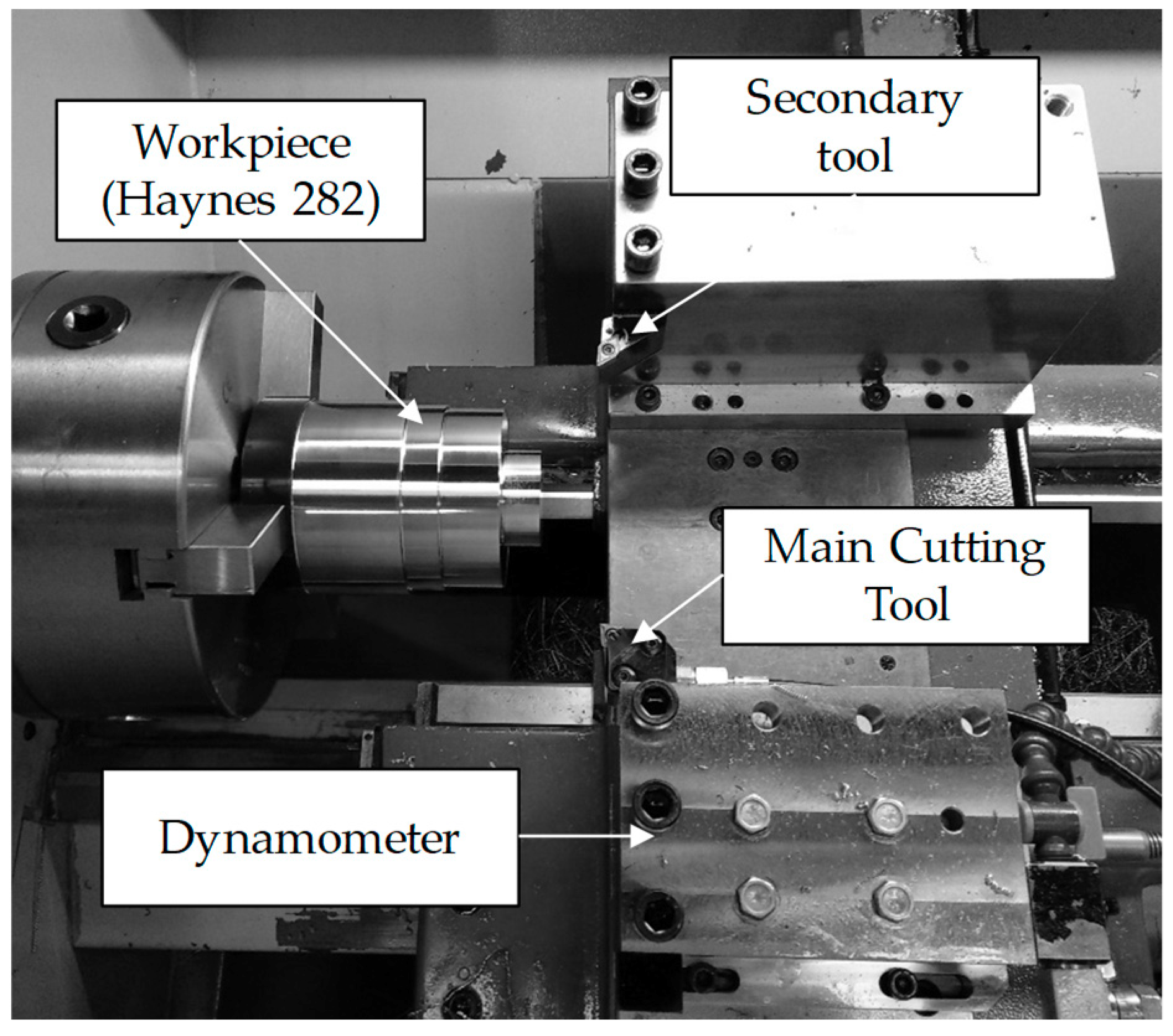
2.2. Experimental Setup and Instrumentation

Haynes 282 turning tests were carried out in a lathe Pinacho Smart turn 6/165 (Pinacho, Castejón del Puente, Spain) equipped with a Kistler 9257B dynamometer (Kistler, Winterthur, Switzerland) for the cutting force measurement (Figure 1).
During the development of the turning tests and at the end of each pass, a rounded surface remained because of the effect of the tool tip radius. Therefore, because of the consequent increase of material needing to be removed in that zone in the next pass, which did not allow for a continuous cut, a sudden increment of undeformed chip cross-section was caused [29]. The finishing operation was characterized by small cutting depths, so this increase in material as a result of the tool tip radius at the end of the pass led to a significant increase in the cutting forces, hence influencing the tool wear. To avoid this phenomenon, a second tool was attached in the tool holder in the lathe (see Figure 1) in order to remove this zone once the cutting force had been stabilized and measured using the tested tool.
The tool wear level was periodically evaluated during the turning tests for each cutting condition, tested by means of obtaining images from a stereo microscope Optika SZR (Optika, Ponteranica BG, Italy). Also, a scanning electron microscopy (SEM) Philips XL-30 (Philips, Eindhoven, Netherlands) with an EDSDX4i system was used to analyze the wear evolution. At the same time, the surface finish of the workpiece was evaluated by means of the surface roughness through a Mitutoyo model SJ-201 (Mitutoyo, Kawasaki, Japan) rugosimeter, obtaining the mean of nine measurements as the representative roughness value.
All of the cutting tests in this study were carried out without any type of coolant by analyzing the finishing turning of Haynes 282 under dry conditions.
As knowledge of the machining of the Haynes 282 alloy at an industrial level is poor, tool manufacturers do not include the relevant information for the selection of the cutting parameters for its process. Nevertheless, in the bibliography, there are general recommendations establishing the ranges for the cutting speed (30–35 m/min), feed rate (0.1–0.18 mm/rev), and depth (1 mm) [31]. Moreover, Díaz-Álvarez et al. [11] investigated the machining of Haynes 282 with carbide tools under a conventional pressure coolant using cutting speeds between 50–90 m/min, feeds between 0.1–0.15 mm/rev, and a depth of pass of 0.25 mm, obtaining a maximum tool life of 33 min. Thus, the cutting parameters selected for the present study are summarized in Table 2.

3. Results and Discussion

3.1. Cutting Forces Analysis

The evolution of the cutting forces—cutting force (Fc), feed force (Ff), and back force (Fp)—were recorded for each preformed test using a frequency of acquisition of 100 Hz. To guarantee the repeatability of the results, each test was performed twice, obtaining deviations lower than 5% with respect to the mean value. Thus, the average values have been used for the subsequent analyses. For the sake of simplicity, in the following analysis, the specific force components (kc, kf, and kp) have been defined as the each of the cutting forces over the undeformed cross section of the chip. In the subsequent points, the results of each component are compared with the observed tool wear damage (notch, chipping, flank, and built up edge).

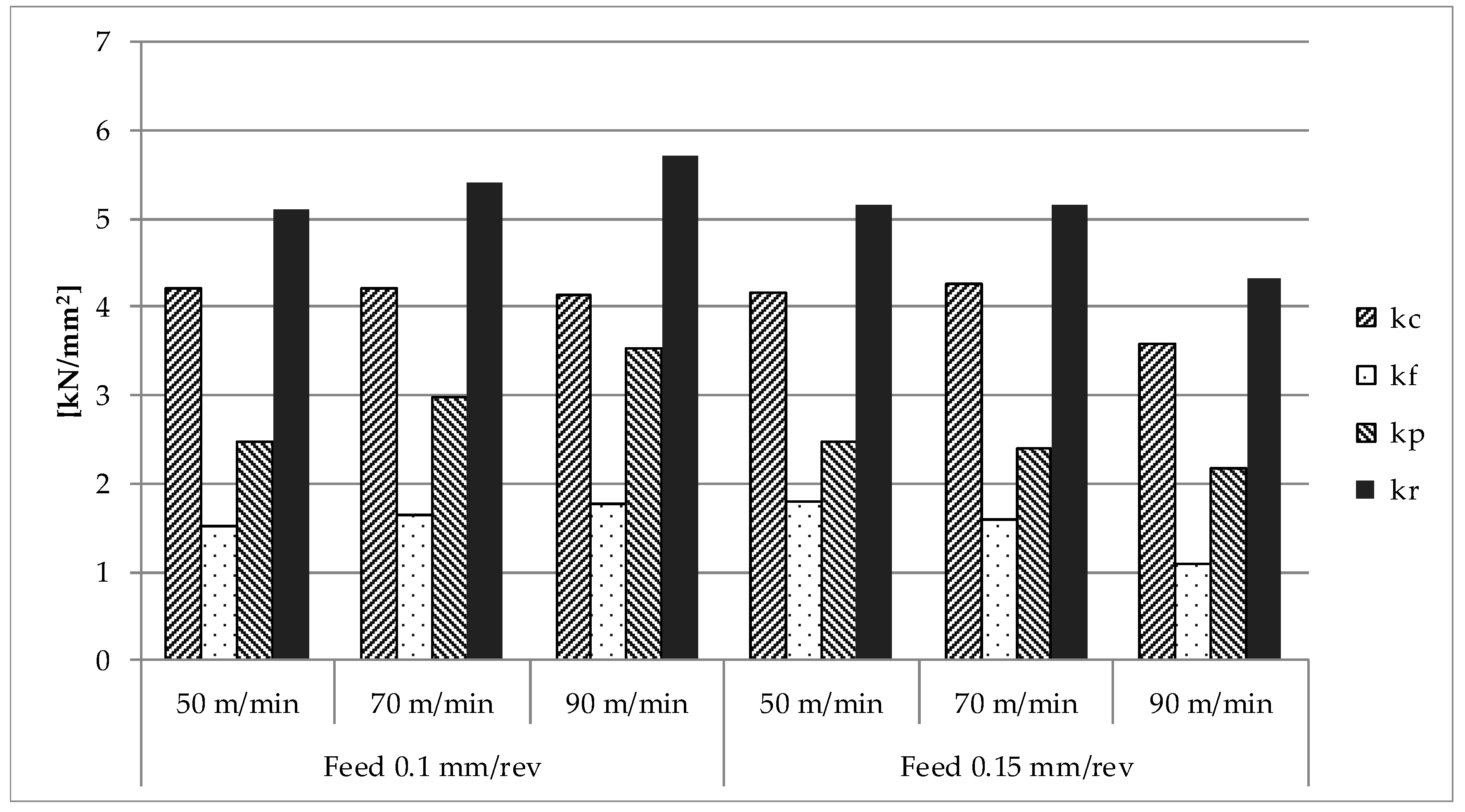
3.1.1. Fresh Tools Results for the Specific Cutting Force

In Figure 2, the obtained results for each component plus the resultant specific cutting force (kr) quantified at the first stages of each of the tests through fresh tools are represented. For the series of cutting parameters that were studied, the results of the specific cutting force (kc) ranged from 3580 N/mm2 (case: Vc = 90 m/min and feed = 0.15 mm/rev) to 4200 N/mm2 (case: Vc = 50 m/min and feed = 0.1 mm/rev). The values of the resultant cutting forces that take into account all of the cutting forces components range from 4330 N/mm2 (case: Vc = 90 m/min and feed = 0.15 mm/rev) to 5700 N/mm2 (case: Vc = 90 m/min and feed = 0.1 mm/rev).

Cutting Speed vs. Specific Cutting Forces

  • For the lowest feed (0.1 mm/rev) used, the specific cutting force (kc) was not significantly affected by the cutting speed for the studied range. However, the rest of the components increased by up to 26% for the specific feed force (kf), and up to 100% for the specific back force (kp) when the cutting speed was increased from 50 m/min to 90 m/min. This behavior was not observed for the feed equal to 0.15 mm/rev, whereas the cutting speed was increased from 50 m/min to 90 m/min, the values of the specific cutting forces were decreased by up to 57%, 70%, and 30% for the specific cutting force (kc), the specific feed force (kf), and the specific back force (kp), respectively. By increasing the cutting speed, the temperature of the material to be cut rose, so that it softened, thus requiring lower cutting forces. At the same time, increasing the cutting speed also increased the strain rate by increasing the resistance of the material to be cut. For a feed of 0.1 mm/rev, it was observed that, because of the higher proportion of chip sections with high levels of deformation, when increasing the cutting speed, the specific cutting forces increased because of the strain hardening effect; however, for the feed value of 0.15 mm/rev, the softening effect of the material, because of the increment of the cutting speed, was the predominant effect.

Feed vs. Specific Cutting Forces

  • Regarding the specific cutting force component induced by the feed, reductions of up to 13% for the specific cutting force (kc), up to 39% for the specific feed force (kf), and up to 38% for the specific back force (kp) were recorded with increments on the feed from 0.1 mm/rev to 0.15 mm/rev. The specific cutting force component induced by the feed was as expected. For the lowest feed, as the proportion of material subjected to large deformation (along the cutting edge) was higher, the specific cutting force results were also higher; this tendency can also be verified through the resultant specific cutting force (kr).

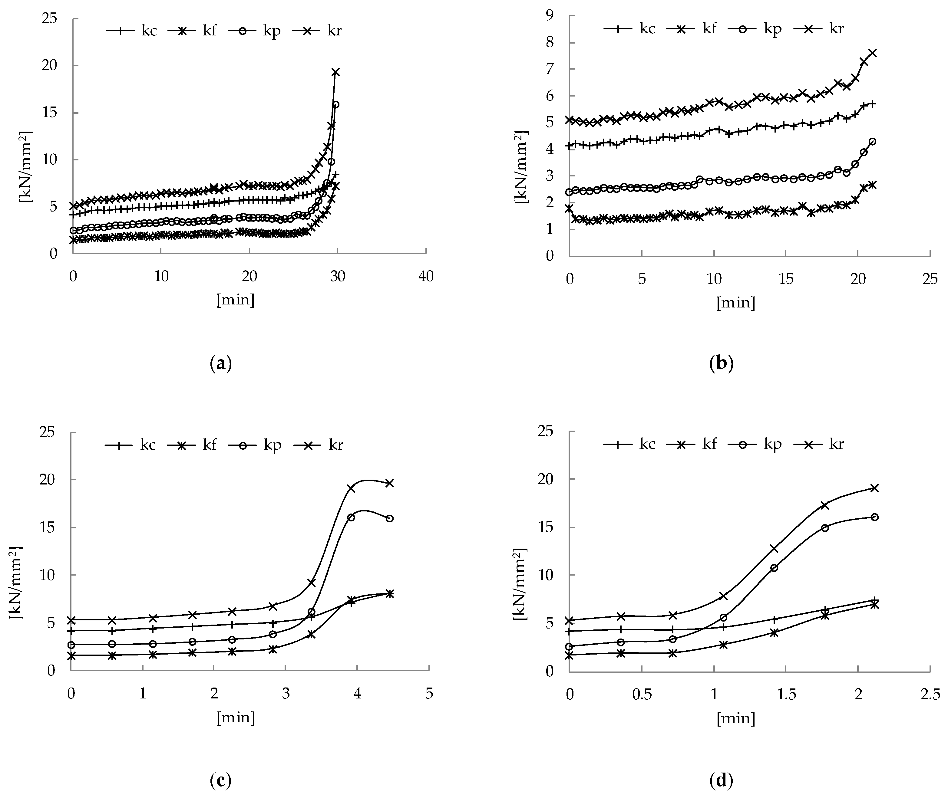
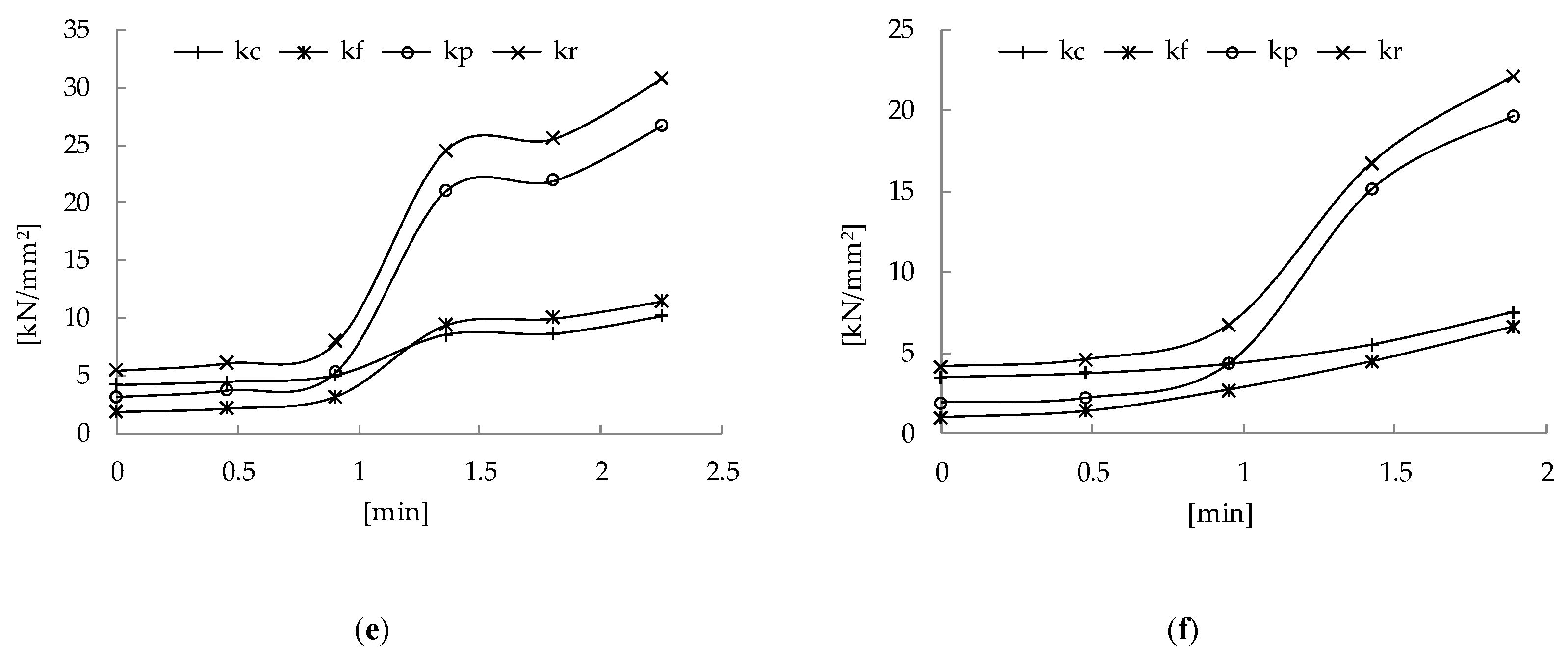
3.1.2. Specific Cutting Forces Evolution During Haynes 282 Turning

The specific force progression and the resultant specific force for the different components with the cutting time are represented in Figure 3. For all of the cutting conditions, all of the specific cutting force components increased with the time of use of the tool. However, kc presented an increasing linear trend for the tool life, while the growth of the kf- and kp-specific forces showed other trends in all of the cases being highlighted in two regions, as follows: the first one with a linear growth and the second one with a more pronounced increment.

Cutting Speed vs. Specific Cutting Forces

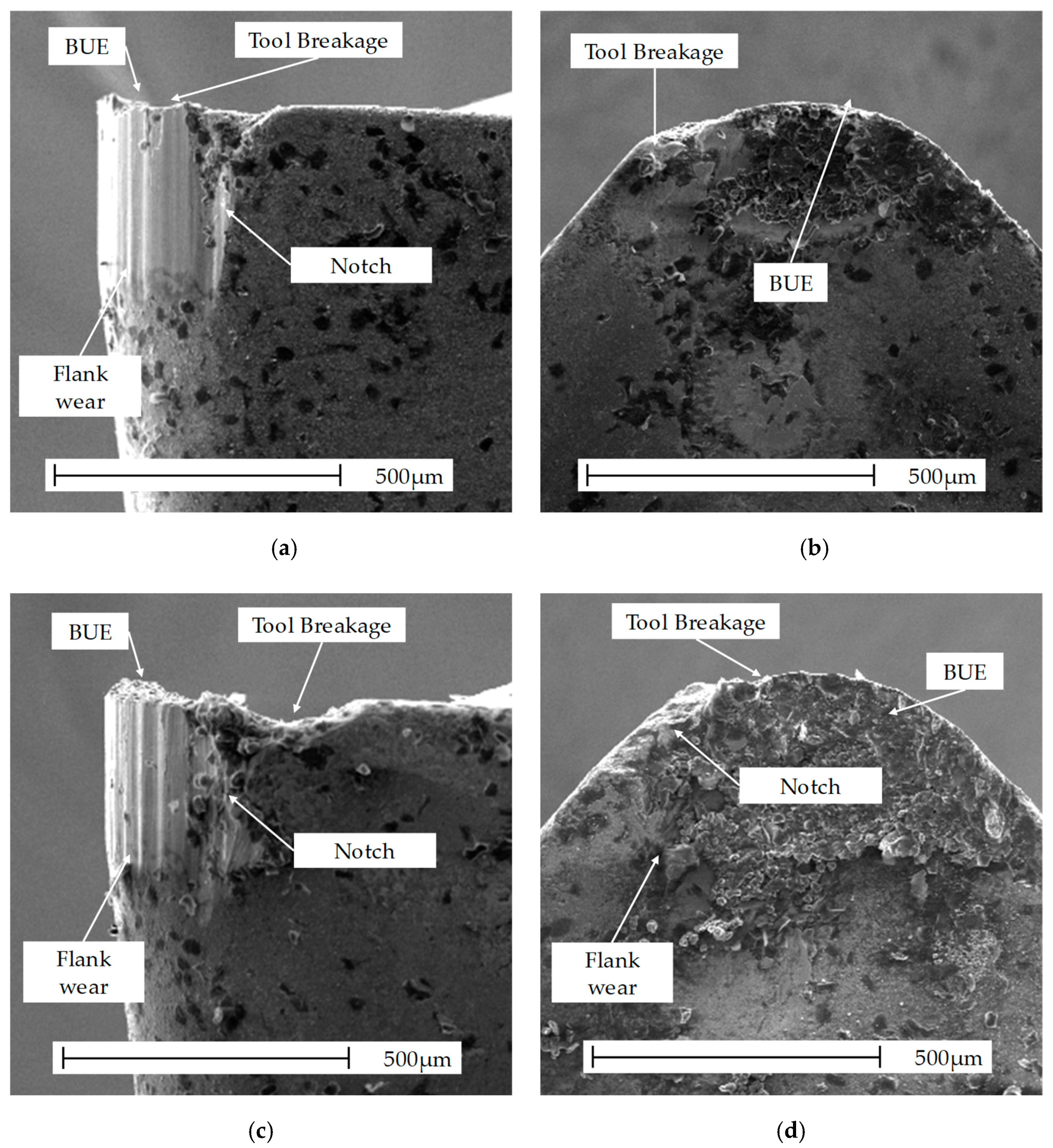
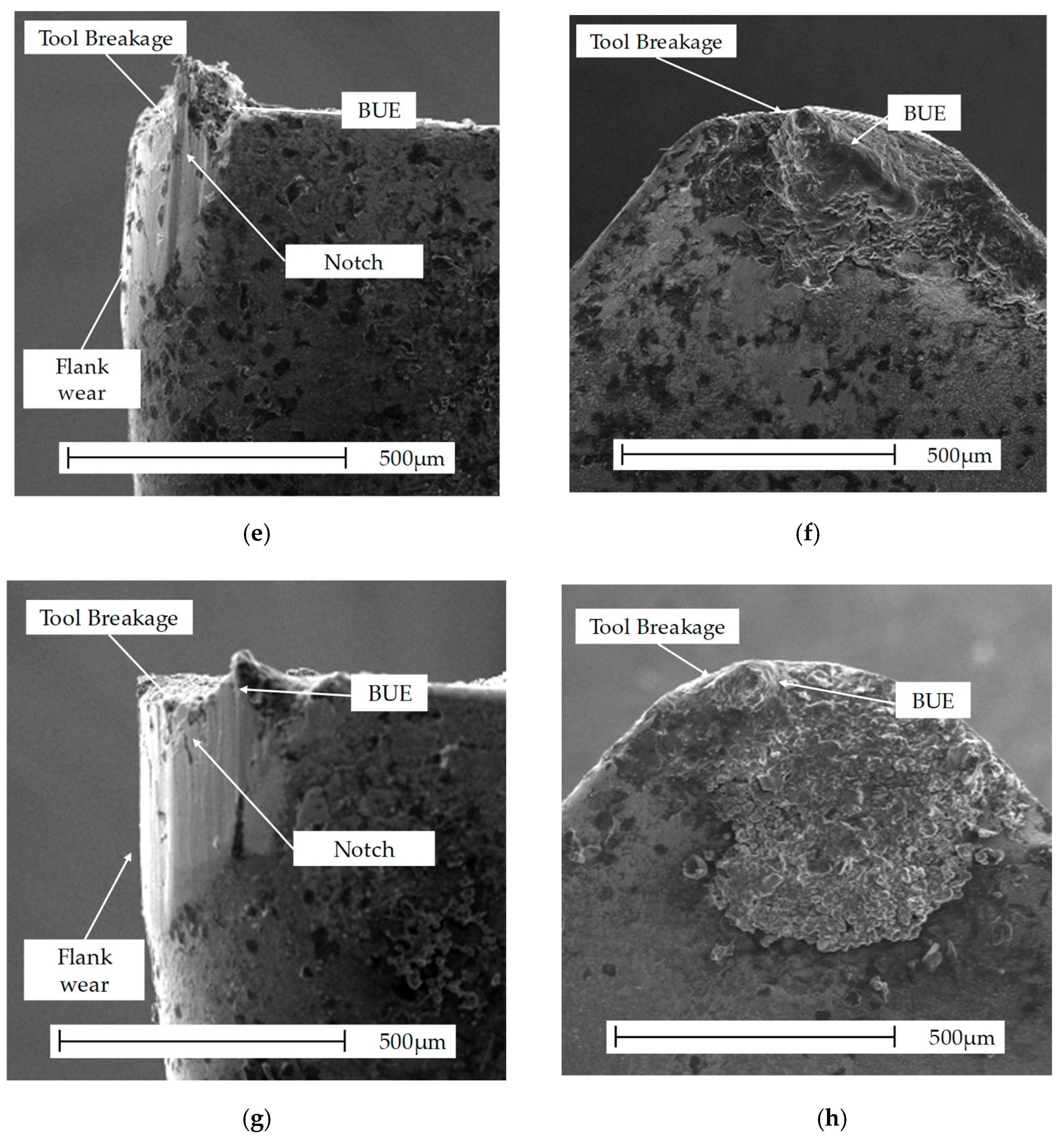
  • Cutting speed 50 m/min: As mentioned in the previous paragraph, a slight linear increase in the cutting forces was recorded in the first region. In the subsequent region, the kp component underwent a drastic increase, contrasting the kf components with a lower increase. These two regions, clearly identifiable during the tests, exhibited a close relationship with the different wear modes observed. Thus, while for the first region of the force evolution a moderate chipping combined with a progressive erosion of the tool flank was observed, for the second region, the kf and kp components of the specific force through the loss of the cutting edge integrity were affected by a more aggressive chipping combined with a rapid progression of the notch. Therefore, a clear trend can be observed, according to which, as the cutting speed increases, both the tool wear rate and consequently the specific forces increase.
  • Cutting speed 70 m/min: The evolution of the specific cutting force showed a similar trend to those obtained for the 50 m/min cutting speed. Thus, for kp, it could be clearly seen in the two regions, with a drastic increase in the second one, whereas for the kf component, this increase was not so evident. Therefore, all of the components of the cutting speed exhibited a slight increase during the first region, with the flank wear progression moderated by means of a light chipping. However, the components of force kf and kp suffered suspected growth during the second region because of a great deterioration of the cutting edge through the notch and more intense chipping in this final stage.
  • Cutting speed of 90 m/min: As in the previous cases, there were two clearly differentiated regions of specific forces of growth, the main difference between them being the use time of the tool, in which the trend change appeared much smaller than for the lower speeds. These two growth zones were also related by a moderate growth of flank wear together with chipping, until the chipping was dominant, progressing in quick increment of the specific force components kf and kp.

Feed vs. Specific Cutting Forces

  • For all of the conditions analyzed, a remarkable influence of the feed on the evolution of the components of the specific cutting force were not found during the turning tests.
Near the end of the tool life, values up to 10 times of those obtained with a fresh tool were obtained for the specific back force, whereas values up to 7 and 2.5 times were obtained for the feed and specific cutting forces respectively, when compared with the ones obtained for the fresh tool. Therefore, especially for lower cutting speeds, the evolution of the specific back force could be a suitable indicator of tool wear progression. The value of the resultant specific cutting force included in Figure 3 can be used as a more stable variable to evaluate the wear state of the tool.

3.2. Analysis of Wear and Tool Life

During each experiment, the test tool wear progression was checked, with the main wear modes identified being the notch, chipping, flank, and built-up edge (BUE). In order to quantify the wear for all of the cutting conditions analyzed, the tool wear was periodically studied within each test. Tools reached the end of tool life by means of the breakage of the cutting edge, or through the end of tool life criterion, established by means of a notch or flank wear larger than 0.4 mm; however, only one cutting condition reached a value of flank wear close to 0.4 mm. The value of 0.4 mm for the notch or flank wear was established by attending to the behavior of the tools, and for values of flank wear close to 0.4 mm, high increments of the cutting forces and a rapid growth of the chipping wear leading to the catastrophic failure of the cutting edge were observed (see Figure 3, Vc = 50 m/min and a feed of 0.1 mm/rev to check the rapid increments of the cutting forces when the value of the flank wear reached values close to 0.4 mm).
Although both BUE and the adhesion of the material were observed for all of the cutting conditions analyzed, as can be seen in Figure 4, they have not supposed a significant influence on the tool life.
Chipping, together with notch wear, were predominant along the entire cutting edge of the tools at the beginning of the performed tests. The wear progression was similar, regardless of the cutting conditions. Chipping became larger, being filled by material (BUE). Furthermore, the area of the notch that grew throughout the tests was clearly differentiated, and, at the same time, the flank wear progressed. It was found that for higher cutting speeds, the chipping progressed more rapidly, exposing more of the flank surface (causing the flank wear to grow much faster than with lower cutting speeds, where chipping was not so aggressive).
The progression of chipping wear is enhanced with the increment of the cutting speed, and, to a lesser extent, by increasing the feed, causing a reduction in the tool life and leading to the final catastrophic breakage of the cutting edge for all of the cases analyzed. Increasing the feed results in obtaining higher forces and a more unstable cut because of the increase of material that is to be removed in each pass, thus, favoring the appearance of fragile breaks in the cutting edge. Increasing the cutting speed is related to an increase in the temperature at the cutting area [12]. This increase in temperature favors the adhesion of materials in the tool (and the consequent chipping) through a reduction of the tool material strength.
In Table 3, both the tool life values by means of cutting time, the machined surface per time (Smach.t) and the machined surface per cutting edge (Sedge), quantified through Equations (1) and (2), respectively, have been summarized for all of the cases analyzed [11].
Smach.t = Vc·f·1000/60
Sedge = Smach.t T·60
where Smach.t is the machined surface per unit time (mm2/s), Sedge is the machined surface per edge (mm2), Vc is the cutting speed (m/min), f is the feed (mm/rev), and T is the tool life (min).
For the lowest cutting speed (50 m/min), values of 30.1 and 21 min of tool life for 0.1 mm/rev and 0.15 mm/rev feeds, respectively, were obtained when reaching the point of the highest level of flank extension (almost 0.4 mm), which is near to the end of tool life criterion that has been established (Figure 4a–d). The end of tool life by means of cutting-edge breakage was reached because of predominant chipping.
Wear due to chipping appears during tests at cutting speeds of 70 m/min, compared with the cutting speed of 50 m/min, reaching the end of tool life through a breakage of the cutting edge. Thus, tool life values of 4.5 and 2.1 min for feeds of 0.1 and 0.15 mm/rev, respectively, were obtained during turning tests at 70 m/min.
In the turning tests at 90 m/min cutting speed, wear due to chipping appeared at the first stages, with a fast progression up to cutting edge breakage at the end of tool life (Figure 4e–h). As expected, the lowest tool life values were reported at 90 m/min, obtaining 2.3 and 1.9 min for feeds of 0.15 and 0.1 mm/rev, respectively.
As shown in Table 3, tool life values of 1.9 (Vc = 90 m/min) up to 30.1 min (Vc = 50 m/min) were obtained during the dry turning tests on Haynes 282. As mentioned above, increasing the cutting speed increased the adhesion of the material in the tool and therefore the chipping wear. Thus, the best results in terms of tool life time were those obtained for both low cutting speeds and feeds. The tool life obtained for the cutting speed of 50 m/min and 0.1 mm/rev feed was very close to those obtained by the authors in analogous tests, where a conventional pressure coolant was used [11]. However, a great influence of the cutting speed in the tool life has been found, decreasing its life up to 85% when the cutting speed increases from 50 to 70 for a feed of 0.1 mm/rev, and up to 90% for a feed of 0.15 mm/rev.
The machined surface per cutting edge (known as an indicator for tool industrial performance) at 50 m/min cutting speed was similar for both feeds (0.1 and 0.15 mm/rev), whereas, because of the short tool life derived from increasing the cutting speed from 70 m/min to 90 m/min, there was no significant variation in the machined surface per cutting edge. It is necessary to highlight the important result obtained in terms of the mechanized surface and tool life for the less aggressive tool parameters (50 m/min and 0.1 mm/rev) in dry conditions, these being very similar to those obtained at the conventional coolant pressure [11]. This result makes the use of this type of tool suitable for the finishing the machining of Haynes 282 under dry conditions, which, until today, was done with cutting fluid.

3.3. Analysis of Surface Quality

The surface roughness progression was evaluated at different stages during the development of the tests. The surface quality was measured three times at three different zones over the machined surfaces in terms of the average roughness (Ra). Thus, the maximum value of these measured values for each stage were taken as the value of the roughness for each condition tested (Figure 5).
During the first stage of tests, with fresh tools and no significant wear, the values of roughness within the range of 0.7 and 2.5 µm were obtained. It should be noted that the Ra values were reduced with the wear of the tool for a cutting speed of 50 m/min, which is related to the type of wear found, with the flank for this cutting speed evolving progressively, reaching values close to 0.4 mm, causing an artificial increase in the tip radius, resulting in lower values of Ra. However, for higher cutting speeds, the chipping was dominant, as the beginning caused the original honing of the cutting edge, which was not so defined. The authors obtained similar results during the finishing turning of Inconel 718 [32].
The best roughness values were those obtained for the 50 m/min cutting speed and 0.1 mm/rev of the feed. This phenomenon is related to the lower chipping obtained at the beginning for the lowest cutting speed, because a more linear trend was observed in the roughness progression.
On the contrary, for cutting speeds of 70 and 90 m/min, where chipping wear affects the tool more severely from the first moments of the test, it has not been possible to establish a clear trend in the roughness progression.
The feed shows a clear influence on the roughness values obtained, with it being generally greater for higher feeds, regardless of the cutting speed. This result agrees with that which is theoretically expected from the application of Equation (3) [33], namely,
Ra = 0.0321·f /rc
where f is the feed (mm/tooth), and rc is the tool nose radius (mm).

4. Conclusions

This work dealt with the sustainable finishing turning of Haynes 282 by means of coated carbide tools without cutting fluids (dry condition). Different cutting speeds and feeds for Ni-based alloys were tested in order to quantify the cutting forces, the quality of surface, the wear progression, and the end of tool life. The main contributions of the analysis are summarized below.
  • The less aggressive conditions for the tool when working on dry conditions are low cutting speeds, 50 m/min in this study. The effect of the feed is not so significant in terms of the mechanized surface, whereas, on the contrary, it is significant in terms of the tool life, with shorter lives having the greatest feed. This effect must be taken into account for productivity purposes.
  • It should be noted that life values similar to those obtained in other studies, with lubricant under similar conditions, have been obtained for the most favorable conditions in dry conditions. This is a significant result, demonstrating the suitability of implementing dry turning in an industrial environment.
  • The great influence of the cutting speed in the tool life was demonstrated by decreasing it by 85% when going from 50 to 70 m/min for a feed of 0.1 mm/rev and 90% for a feed of 0.15 mm/rev.
  • Great increases in cutting forces have been appreciated for all of the tested conditions, obtaining values for the specific back force at the end of tool life, of 10 times the value obtained when the tool was fresh. It has been possible to observe a clear relationship between this force and the tool life.
  • Regarding the wear, since the beginning of the trials, chipping, built up edge (BUE), and notch wear were found. The catastrophic failure of the cutting edge has been found at the end of tool life in all of the cutting conditions tested because of the chipping progression.
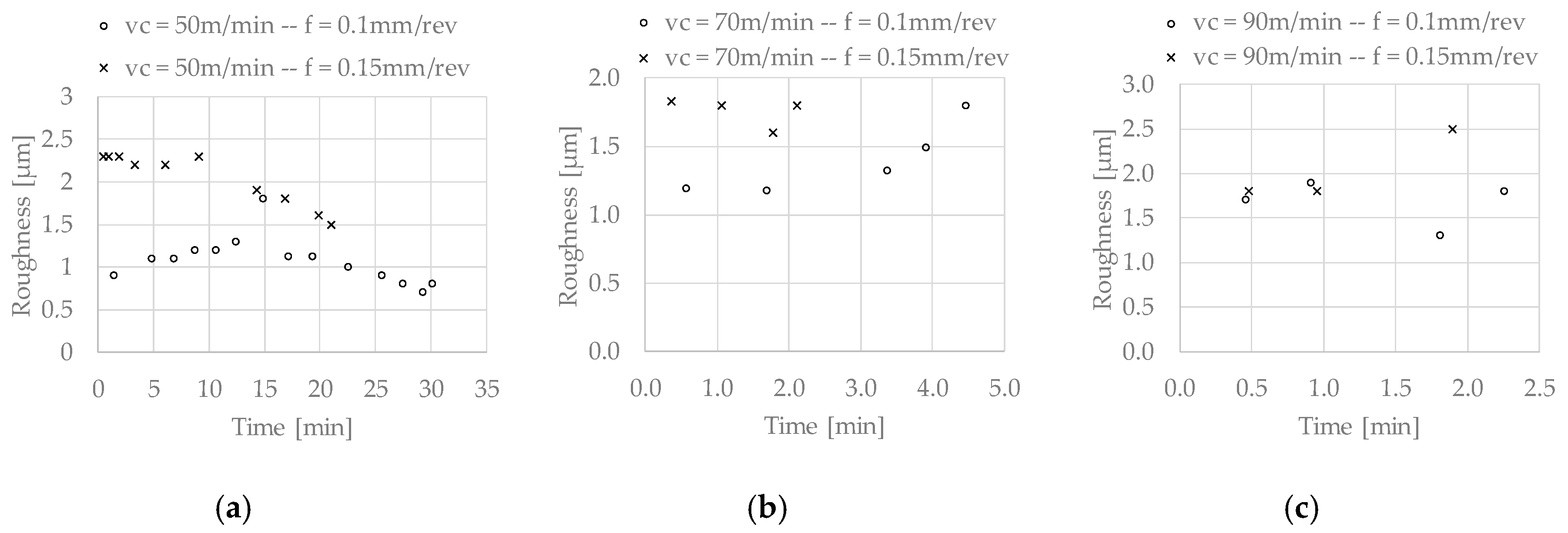
  • For all of the tests, the Ra values were low, regardless of the time of use of the tool (between 0.7 and 2.5 µm). However, the homogeneity in terms of Ra for the test with a 50 cutting speed and 0.1 mm/rev of feed stands out, which gives one an idea of the stability of this condition in relation to the other cutting parameters, where large variations in this value were found.

Author Contributions

Conceptualization, J.D.-Á. and J.L.C.; data curation, J.D.-Á. and A.D.-Á.; formal analysis, J.D.-Á., A.D.-Á., and J.L.C.; funding acquisition, H.M. and J.L.C.; investigation, J.D.-Á. and A.D.-Á.; project administration, H.M. and J.L.C.; resources, J.L.C.; supervision, H.M. and J.L.C.; validation, J.D.-Á., A.D.-Á., H.M., and J.L.C.; visualization, A.D.-Á.; writing (original draft), J.D.-Á. and A.D.-Á.; writing (review and editing), A.D.-Á., J.D.-Á., and H.M.

Funding

This research was funded by the Ministry of Economy, Industry, and Competitiveness, and the FEDER program, grant number DPI2017-89197-C2-1-R.

Conflicts of Interest

The authors declare no conflict of interest.

References

  1. Hu, D.; Wang, T.; Ma, Q.; Liu, X.; Shang, L.; Li, D.; Pan, J.; Wang, R. Effect of inclusions on low cycle fatigue lifetime in a powder metallurgy nickel-based superalloy FGH96. Int. J. Fatigue 2019, 118, 237–248. [Google Scholar] [CrossRef]
  2. Zhu, D.; Zhang, X.; Ding, H. Tool wear characteristics in machining of nickel-based superalloys. Int. J. Mach. Tools Manuf. 2013, 64, 60–77. [Google Scholar] [CrossRef]
  3. Cantero, J.L.; Díaz-Álvarez, J.; Miguélez, M.H.; Marín, N.C. Analysis of tool wear patterns in finishing turning of Inconel 718. Wear 2013, 297, 885–894. [Google Scholar] [CrossRef] [Green Version]
  4. Ezugwu, E.O.; Bonney, J.; Yamane, Y. An overview of the machinability of aeroengine alloys. J. Mater. Process. Technol. 2003, 134, 233–253. [Google Scholar] [CrossRef]
  5. Wang, F.; Cheng, X.; Liu, Y.; Yang, X.; Meng, F. Micromilling Simulation for the Hard-to-cut Material. Procedia Eng. 2017, 174, 693–699. [Google Scholar] [CrossRef]
  6. Thakur, A.; Gangopadhyay, S. State-of-the-art in surface integrity in machining of nickel-based super alloys. Int. J. Mach. Tools Manuf. 2016, 100, 25–54. [Google Scholar] [CrossRef]
  7. Kruger, K.L. HAYNES 282 Alloy; Elsevier Ltd.: Amsterdam, The Netherlands, 2016; ISBN 9780081005583. [Google Scholar]
  8. Donachie, M.J. Superalloys: A Technical Guide, 2nd ed.; ASM International: New York, NY, USA, 2002; pp. 1–409. [Google Scholar]
  9. Shin, K.Y.; Kim, J.H.; Terner, M.; Kong, B.O.; Hong, H.U. Effects of heat treatment on the microstructure evolution and the high-temperature tensile properties of Haynes 282 superalloy. Mater. Sci. Eng. A 2019, 751, 311–322. [Google Scholar] [CrossRef]
  10. Rodríguez-Millán, M.; Díaz-Álvarez, J.; Bernier, R.; Cantero, J.; Rusinek, A.; Miguelez, M. Thermo-Viscoplastic Behavior of Ni-Based Superalloy Haynes 282 and Its Application to Machining Simulation. Metals 2017, 7, 561. [Google Scholar] [CrossRef]
  11. Díaz-Álvarez, J.; Díaz-Álvarez, A.; Miguélez, H.; Cantero, J. Finishing Turning of Ni Superalloy Haynes 282. Metals 2018, 8, 843. [Google Scholar] [CrossRef]
  12. Díaz-Álvarez, J.; Tapetado, A.; Vázquez, C.; Miguélez, H. Temperature measurement and numerical prediction in machining inconel 718. Sensors 2017, 17, 1531. [Google Scholar] [CrossRef]
  13. Ezugwu, E.O. Key improvements in the machining of difficult-to-cut aerospace superalloys. Int. J. Mach. Tools Manuf. 2005, 45, 1353–1367. [Google Scholar] [CrossRef]
  14. Choudhury, I.; El-Baradie, M. Machinability of nickel-base super alloys: A general review. J. Mater. Process. Technol. 1998, 77, 278–284. [Google Scholar] [CrossRef]
  15. Muñoz-Sánchez, A.; Canteli, J.A.; Cantero, J.L.; Miguélez, M.H. Numerical analysis of the tool wear effect in the machining induced residual stresses. Simul. Model. Pract. Theory 2011, 19, 872–886. [Google Scholar] [CrossRef] [Green Version]
  16. Urbikain, G.; de Lacalle, L.N.L. Modelling of surface roughness in inclined milling operations with circle-segment end mills. Simul. Model. Pract. Theory 2018, 84, 161–176. [Google Scholar] [CrossRef]
  17. Hoier, P.; Malakizadi, A.; Stuppa, P.; Cedergren, S.; Klement, U. Microstructural characteristics of Alloy 718 and Waspaloy and their influence on flank wear during turning. Wear 2018, 400–401, 184–193. [Google Scholar] [CrossRef]
  18. Thellaputta, G.R.; Chandra, P.S.; Rao, C.S.P. Machinability of Nickel Based Superalloys: A Review. Mater. Today Proc. 2017, 4, 3712–3721. [Google Scholar] [CrossRef]
  19. Grzesik, W.; Niesłony, P.; Habrat, W.; Sieniawski, J.; Laskowski, P. Investigation of tool wear in the turning of Inconel 718 superalloy in terms of process performance and productivity enhancement. Tribol. Int. 2018, 118, 337–346. [Google Scholar] [CrossRef]
  20. Thakur, D.G.; Ramamoorthy, B.; Vijayaraghavan, L. Study on the machinability characteristics of superalloy Inconel 718 during high speed turning. Mater. Des. 2009, 30, 1718–1725. [Google Scholar] [CrossRef]
  21. Bouzakis, K.D.; Michailidis, N.; Skordaris, G.; Bouzakis, E.; Biermann, D.; M’Saoubi, R. Cutting with coated tools: Coating technologies, characterization methods and performance optimization. CIRP Ann. Manuf. Technol. 2012, 61, 703–723. [Google Scholar] [CrossRef]
  22. Olovsjö, S.; Nyborg, L. Influence of microstructure on wear behaviour of uncoated WC tools in turning of Alloy 718 and Waspaloy. Wear 2012, 282–283, 12–21. [Google Scholar] [CrossRef]
  23. Goindi, G.S.; Sarkar, P. Dry machining: A step towards sustainable machining—Challenges and future directions. J. Clean. Prod. 2017, 165, 1557–1571. [Google Scholar] [CrossRef]
  24. Devillez, A.; Schneider, F.; Dominiak, S.; Dudzinski, D.; Larrouquere, D. Cutting forces and wear in dry machining of Inconel 718 with coated carbide tools. Wear 2007, 262, 931–942. [Google Scholar] [CrossRef]
  25. Gajrani, K.K.; Suvin, P.S.; Kailas, S.V.; Sankar, M.R. Hard machining performance of indigenously developed green cutting fluid using flood cooling and minimum quantity cutting fluid. J. Clean. Prod. 2019, 206, 108–123. [Google Scholar] [CrossRef]
  26. Amiril, S.A.S.; Rahim, E.A.; Syahrullail, S. A review on ionic liquids as sustainable lubricants in manufacturing and engineering: Recent research, performance, and applications. J. Clean. Prod. 2017, 168, 1571–1589. [Google Scholar] [CrossRef] [Green Version]
  27. Gutnichenko, O.; Bushlya, V.; Bihagen, S.; Ståhl, J.-E. Influence of GnP additive to vegetable oil on machining performance when MQL-assisted turning Alloy 718. Procedia Manuf. 2018, 25, 330–337. [Google Scholar] [CrossRef]
  28. Gajrani, K.K.; Ram, D.; Ravi Sankar, M. Biodegradation and hard machining performance comparison of eco-friendly cutting fluid and mineral oil using flood cooling and minimum quantity cutting fluid techniques. J. Clean. Prod. 2017, 165, 1420–1435. [Google Scholar] [CrossRef]
  29. Cantero, J.; Díaz-Álvarez, J.; Infante-García, D.; Rodríguez, M.; Criado, V. High Speed Finish Turning of Inconel 718 Using PCBN Tools under Dry Conditions. Metals 2018, 8, 192. [Google Scholar] [CrossRef]
  30. Suárez, A.; Veiga, F.; de Lacalle, L.N.L.; Polvorosa, R.; Wretland, A. An investigation of cutting forces and tool wear in turning of Haynes 282. J. Manuf. Process. 2019, 37, 529–540. [Google Scholar] [CrossRef]
  31. Pike, L.M.; Weatherhill, A.E. HAYNES® 282TM Alloy: A New Wrought Superalloy Designed for Improved Creep Strength and Fabrication Ability; ASME: New York, NY, USA, 2006; pp. 1031–1039. [Google Scholar]
  32. Díaz-Álvarez, J.; Criado, V.; Miguélez, H.; Cantero, J. PCBN Performance in High Speed Finishing Turning of Inconel 718. Metals 2018, 8, 582. [Google Scholar] [CrossRef]
  33. Asiltürk, I.; Çunkas, M. Expert Systems with Applications Modeling and prediction of surface roughness in turning operations using artificial neural network and multiple regression method. Expert Syst. Appl. 2011, 38, 5826–5832. [Google Scholar] [CrossRef]
Figure 1. Instrumentation and setup.
Metals 09 00989 g001
Figure 2. Specific cutting forces for fresh carbide tools at the beginning of the tests.
Metals 09 00989 g002
Figure 3. Specific cutting force evolutions with the times for the different cutting conditions tested. (a) Vc = 50 m/min and f = 0.1 mm/rev; (b) Vc = 50 m/min and f = 0.15 mm/rev; (c) Vc = 70 m/min and f = 0.1 mm/rev; (d) Vc = 70 m/min and f = 0.15 mm/rev; (e) Vc = 90 m/min and f = 0.1 mm/rev; (f) Vc = 90 m/min and f = 0.15 mm/rev.
Metals 09 00989 g003aMetals 09 00989 g003b
Figure 4. Scanning electron microscopy (SEM) images at the end of the tool life for the different conditions tested. Vc = 50 m/min and f = 0.1 mm/rev: (a) relief and (b) rake surface view. Vc = 50 m/min and f = 0.15 mm/rev: (c) relief and (d) rake surface view. Vc = 90 m/min and f = 0.1 mm/rev: (e) relief and (f) rake surface view. Vc = 90 m/min f = 0.15 mm/rev: (g) relief and (h) rake surface view. BUE—built up edge.
Metals 09 00989 g004aMetals 09 00989 g004b
Figure 5. Roughness evolution at the machined surface for all of the cutting conditions tested: (a) Vc = 50 m/min, (b) Vc = 70 m/min, (c) Vc = 90 m/min.
Metals 09 00989 g005
Table 1. Haynes 282 chemical composition [11].
Element (%)NiCrFeNbMoTiAlCoSiCuMnC
Haynes 2825719.420.87˂0.018.522.221.4110.2˂0.05˂0.010.060.062
Table 2. Cutting parameters for the turning tests.
Cutting Speed (m/min)Feed (rev/min)Pass Depth (mm)
500.10.25
0.15
700.1
0.15
900.1
0.15
Table 3. Tool life, machined surface per unit time (mm2/s), and machined surface per edge (mm2) for the different cutting conditions tested.
ToolCutting Speed (m/min)Feed (mm/rev)Depth (mm)Life (min)Machined Surface per Unit Time (mm2/s)Machined Surface per Cutting Edge (mm2)
Carbide (TS2000, Seco)500.10.2530.183.3150,520
0.1521.0125.0157,629
700.10.254.511731,196
0.152.1175.022,266
900.10.252.3150.020,263
0.151.9225.025,525

