1. Introduction
Failure time and temperature of the column is important information in estimating the resistance capacity of a column in a fire situation. Most investigations conducted on individual columns evaluate the failure time and temperature. Cold-formed steel (CFS) is a very sensitive material due to its thinner width, which is perceived to have low resistance when on fire. The thermal conductivity of material and the section factor of CFS contribute to low fire resistance [
1]. Currently, the estimation of CFS capacity in EN 1993-1-2:2005 is based on hot-rolled steel with a Class 4 cross-section. The prediction includes the variety of buckling mode, i.e., local, global, and distortional buckling, and their interactions [
2]. Besides that, the degradation of material strength of CFS under fire conditions was found to be the dominant factor influencing fire resistance [
3].
The application of CFS material as a column structure has recently widened due to its advantages at ambient temperature. Therefore, the evaluation of a CFS column under fire conditions is relevant. CFS is a production material that is normally formed into open sections. The large sections are usually used for purlin and columns. The open sections, such as the channel section, are prone to have a variety of buckling modes, such as local, global, and distortional buckling. To minimize buckling failures, the open sections are upgraded as close sections by joining two channels back to back (BTB) or box up (BU) for better strength and stability.
To date, many studies have conducted strength tests on CFS column with various section configurations. The BTB member deforms in local buckling between the connections, and on each end, and fails with a smooth curve with the flange buckling near mid-span [
4]. BTB columns were extensively studied by Jakab [
5], Georgieva et al. [
6], and Xu et al. [
7]. BU columns were studied by Dunai [
8], Young and Chen [
9], Liu et al. [
10], Whittle and Ramseyer [
11], Reyes and Guzmán [
12], and Piyawat et al. [
13]. All studies were conducted at ambient temperature. In addition, information about CFS at elevated temperature is widely available since most CFS has been used in a wall frame system. The CFS is usually covered with gypsum board or embedded in concrete. The CFS is not directly exposed to fire, making the study of CFS under elevated temperature relevant. Feng et al. [
1] has conducted elevated-temperature tests on short CFS columns. Column imperfections have a great effect on column failure mode, but the failure mode is identical at both ambient and high temperature.
Studies of CFS structure exposed directly to fire are still limited. One study was conducted by Laím & Rodrigues [
2], who proposed a new fire design method for CFS beams. From their analysis, they found that the value of limiting temperature 350 °C for a Class 4 section as recommended in EN 1993-1-2:2005 is not suitable for beam fire design, especially under lower degrees of use, i.e., 30%. It has a high critical temperature of greater than 500 °C. The study conducted by Naser & Degtyareva [
14] reported that the fire performance of CFS beam-slotted webs at high temperature significantly exceeds the Eurocode 3 limit of 350 °C. In addition, CFS beam-slotted webs are very sensitive to shear loading under fire conditions. The use of a CFS column has widened due to the availability of information on its strength, behavior, and design guidelines. Recently, a few experimental studies on the real fire behavior of CFS columns have been conducted.
Gardner and Baddoo [
15] conducted a few tests on an unprotected stainless-steel structure subjected to the ISO 834 fire standard. The test involved three rectangular hollow sections, which were columns Class 1–3 cross-sections that were built up from tip-to-tip weld along the length of two cold-rolled channels and one I-section with Class 4 cross-section that was built up from two cold-rolled channels welded back to back along the length. The critical temperature and fire resistance of the hollow sections were higher than the critical temperature of the I-section. The I-section had a lower fire resistance due to the non-symmetric heating around the section that caused excessive thermal bowing.
Currently, no study has investigated the effect of cross-sectional shape directly. Individual tests on hollow rectangular shape and I-shape have been undertaken. Tondini et al. [
16] conducted a test at room temperature prior to fire testing. The study fully identified the effect of fire-loading on square hollow sections (SHS) and rectangular hollow sections (RHS) of different lengths. Initially, the fire curve did not follow the ISO 834 fire; however, after five minutes, the curve was close to the standard. The axial deformation was calculated by averaging the left and right displacements of the transducer. The column expanded due to thermal expansion, and shortened quickly due to increasing lateral deflection during failure. Time and temperature were taken when the column failed. The column buckled about the weak axis. Two clear spatial plastic mechanisms formed at approximately the top and mid-height of the column. This mechanism happened due to the non-uniform temperature gradient along the length, where the top of the furnace, for all tests, was warmer compared to the bottom end. The recorded temperature might be lower than the actual temperature of the column, which resulted in the conservative temperature value.
The only test for CFS subjected to fire has been conducted by Craveiro et al. [
17]. Restraint thermal elongation slender channel and I-section with the arrangement of BTB with different types of cross-sections, end support conditions, and initial applied load levels were studied. The semi-rigid and pin-ended support conditions for both section types of CFS column with higher initial load level were experienced at the lower critical temperature. The heating rate was identical for each section type, load level, and boundary condition. The temperature evolution for the channel section was uniform, while for the I-section it varied. The web temperature was cooler due to greater thickness and thermal conductance between the CFS profiles. The heating rate considered at the first 100 °C of the channel section was higher at 76.2 °C/min as compared to the built-up I-section at 60.38 °C/min. The higher initial applied load resulted in lower critical time and temperature. The furnace temperature reaches the temperature of the ISO 834 fire standard is about 5 minutes and 6 minutes for channel and I-section column, respectively.
Previous studies have contained limited information on the effect of different cross-section types on the failure time and temperature of CFS columns. Hence, experimental investigation and analysis on CFS columns subjected to fire were conducted at the Construction Research Center (CRC), Universiti Teknologi Malaysia, Skudai, Malaysia. The study involved three types of column cross-sections, i.e., channel, BTB, and BU columns with two or three degrees of use with constant constraint. The objective of this study was to evaluate the effect of different cross-section types on the time and temperature failure of CFS columns when subjected to the ISO 834 fire standard.
2. Materials and Method
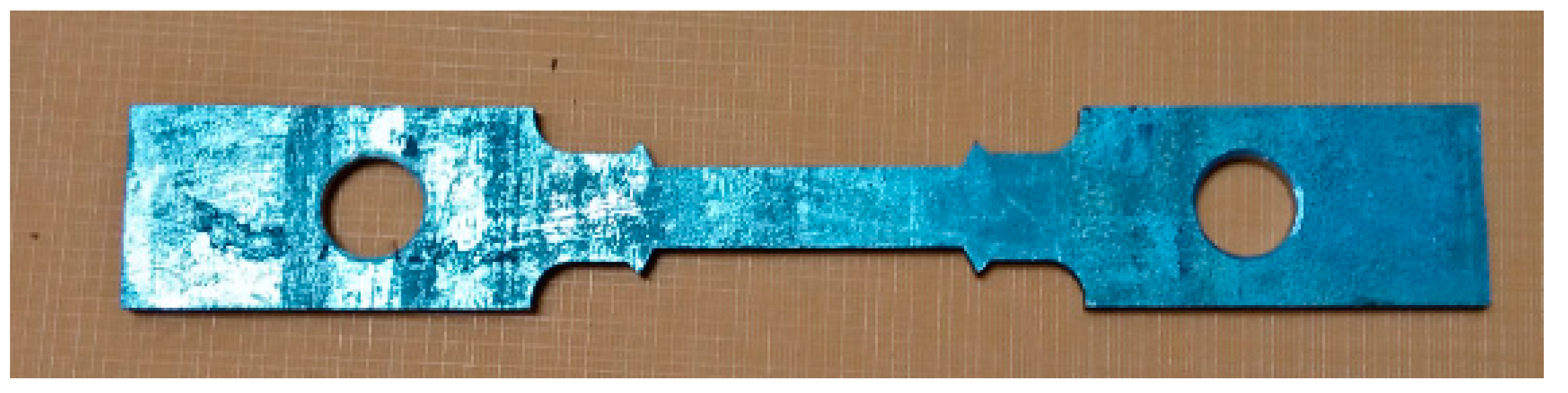
The CFS channel section was supplied by the local CFS manufacture in southern Malaysia. The size of the section was 200 mm web depth, 73 mm flange width, 17 mm lipped size, 1.9 mm thickness, 2.5 mm round corner, and the centroid was 20.38 mm from the web. The evaluation of CFS material properties at elevated temperature was conducted under a steady-state test. The sample size followed BS EN 10002-1:2001 as shown in
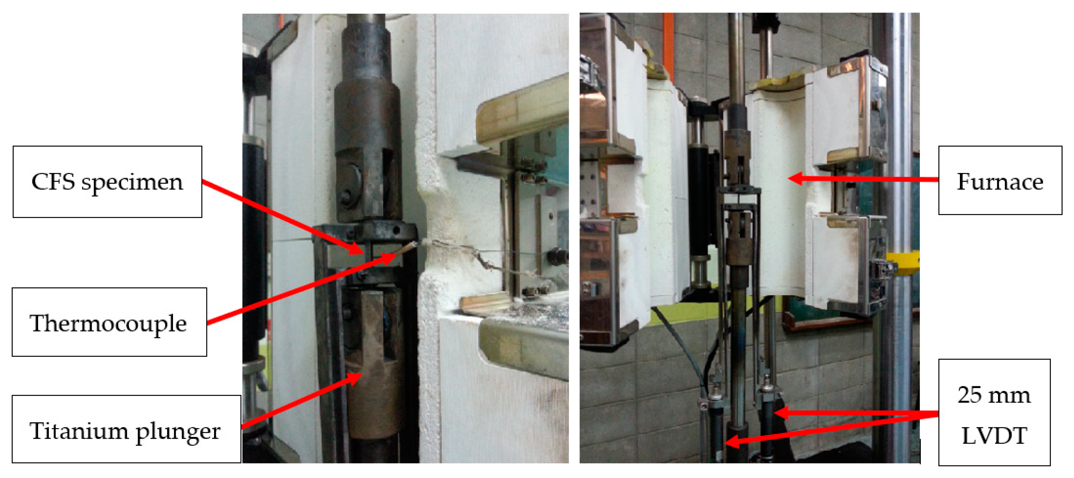
Figure 1. The test is conducted by using a Universal Tensile Machine (Instron, Skudai, Malaysia) together with a furnace. The temperature range is 100–800 °C. The arrangement of the test is illustrated in
Figure 2. Two amounts of 25 mm Linear Variable Displacement Transducer (LVDT) were used to get the elongation of the CFS from the initial of temperature to failure. The furnace was covered with ceramic fiber on the top, bottom, and front of the furnace opening to contain the temperature. The specimen was placed in the center of the furnace. It was attached to the extended support to provide tensile stress of the specimen. Thermocouple type K was attached to the specimen surface to measure the CFS temperature. Then, the specimens of ambient and 600 °C were cut to around 5 mm × 5 mm for chemical composition testing using energy-dispersive X-ray spectroscopy (EDX, ZEISS GeminiSEM, Skudai, Malaysia).
Two channel sections with a length of 3 m were attached, known as BTB and BU sections, as shown in
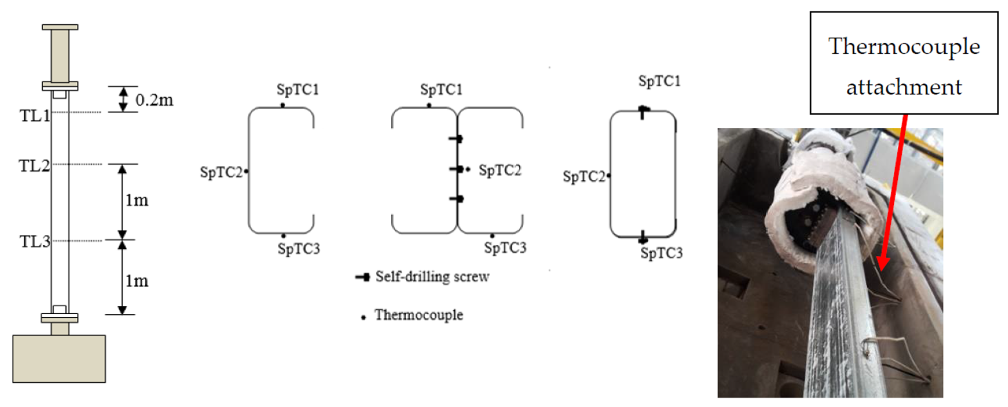
Figure 3. The channel was connected by using self-drilling screws with spacing at 400 mm center to center along the length. The column was restrained by using a screw at both columns ends with a steel angle plate to prevent lateral movement. The angle plate and channel were sat on a circular steel plate for uniform load distribution on the column cross-section. The boundary condition was considered to be semi-rigid. The column was unrestraint in thermal elongation to allow an axial expansion during a fire. All support facilities and accessories were coated with 3 mm-high temperature coated (Heat Resisting Aluminum, 600 °C) paint to prevent expansion during fire. 20-mm ceramic fibers that can exposed to up to 1260 °C under continuous use were added to cover the steel plate. The temperature of the end support was monitored by a thermocouple. It was observed that the temperature was less than 100 °C.
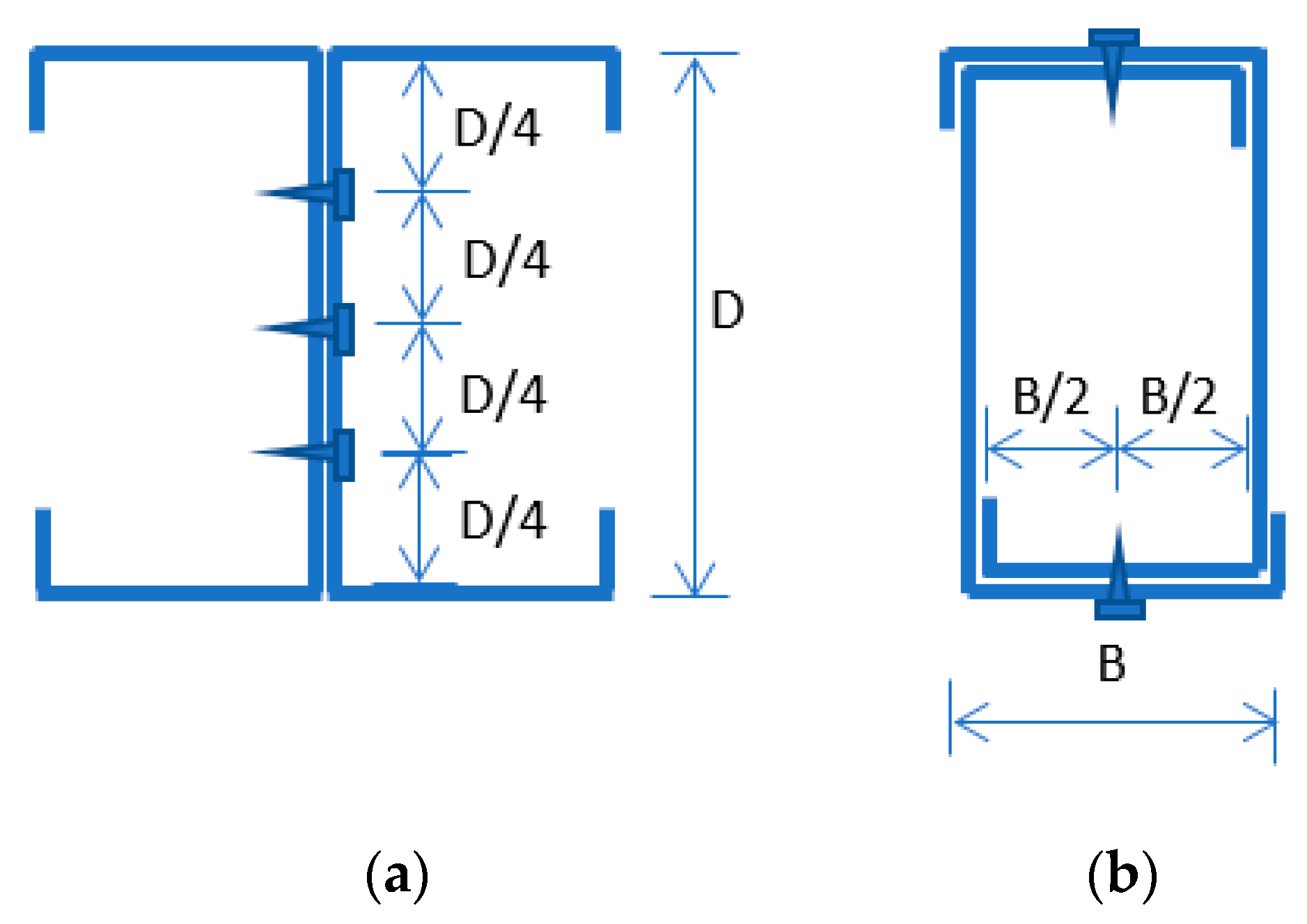
A Type K thermocouple was used to monitor temperature changes on the column surface. It was located along the column length based on the BS EN 13381-4:2013 (E) recommendation. It was attached by a screw on the column surface. Initially, the thermocouple was planned to be welded to the column surface. Since this experiment involves the reuse of the thermocouple, to avoid thermocouple damage, and to obtain reliable temperature data, the attachment was simplified by using screws. In addition, the width of CFS is thin, so welding was not the best option. The thermocouple was attached at 3 locations along the column’s length, specifically TL1, TL2, and TL3. The location and specific name of the thermocouple at each level is shown in
Table 1. The thermocouple was attached to the column section at the flange and the web. The detail position of all thermocouples in this study is shown in
Figure 4.
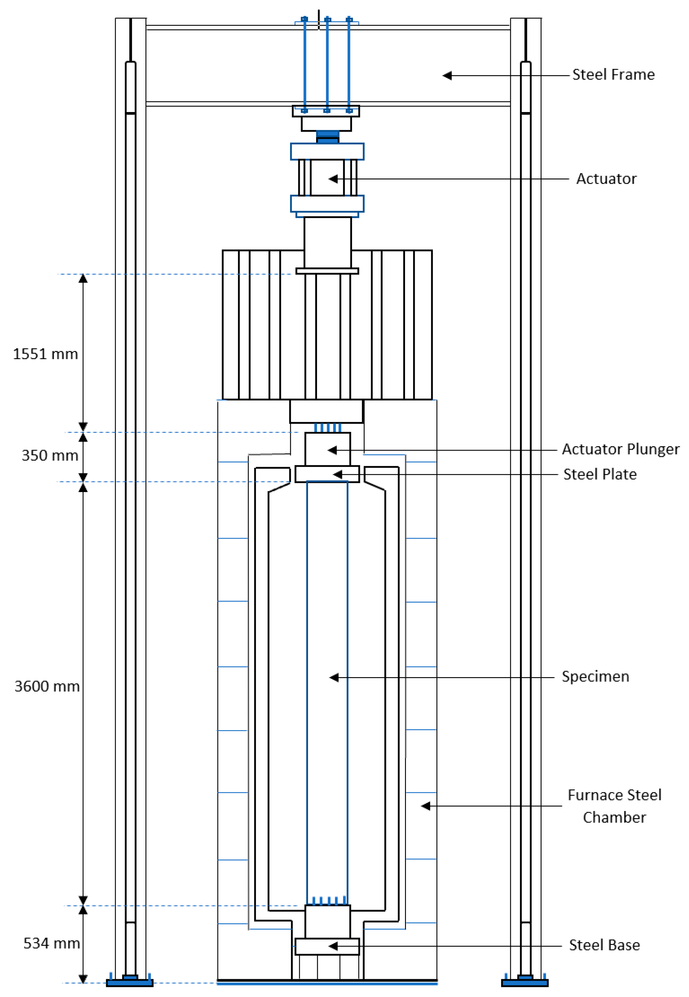
A static test was conducted at ambient temperature to determine the capacity of all the column types. According to this static test, a load ratio known as the degree of utilization was applied during the fire test. The column was loaded at three different constant load levels, i.e., 30%, 50%, and 70% degree of utilization. It was loaded by using a hydraulic jack loading system with a maximum loading of 1000 kN and a loading rate of 0.25 kN/s. The column was placed in a furnace to simulate the ISO 834 fire exposure standard, as shown in
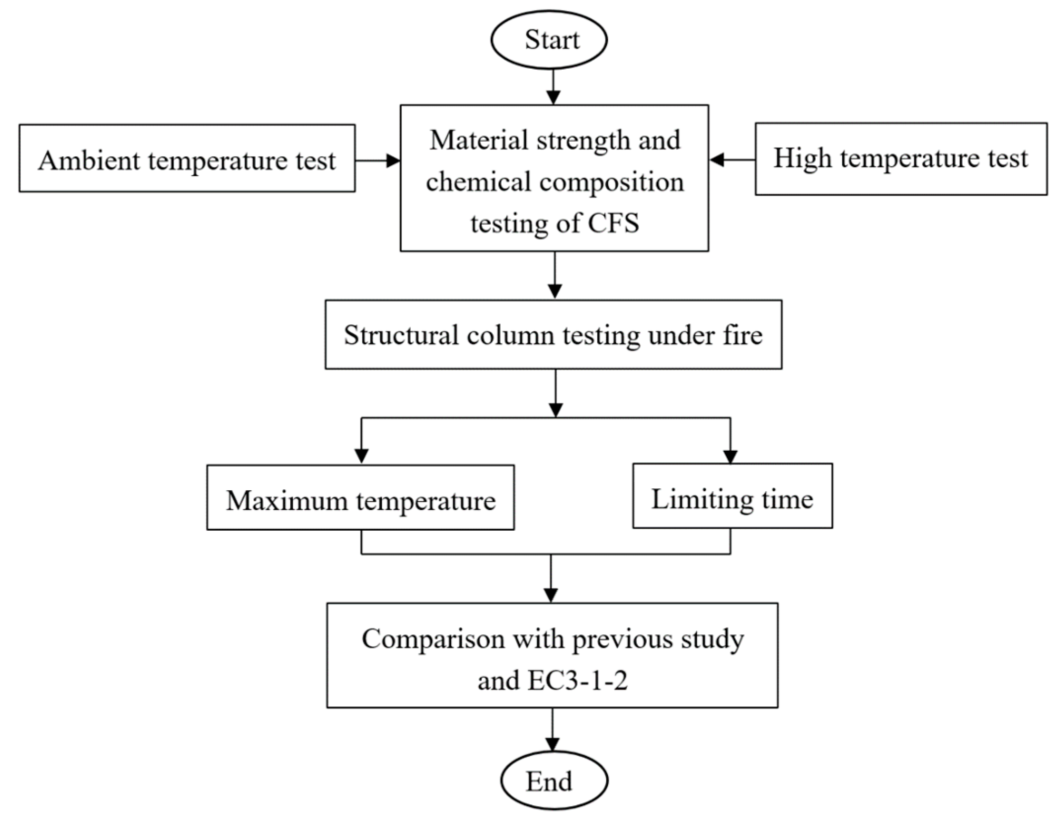
Figure 5. The load was left constant until it reached a stable condition for 15 min, then the fire was induced. The gas furnace consisted of 6 fire blowers at the bottom, middle, and top. The average of those 6 blowers was determined by the overall furnace temperature inside the column. The column was considered to have failed when the constant load dropped significantly. Since the column was placed in a sealed furnace, the failure mode during the test cannot be observed. The final mode shape after the column cooled was obtained. The summary of the research methodology is shown in
Figure 6.
The temperature inside the furnace ensured that the ISO 834 fire standard curve was followed within an acceptable range of 15% percentage deviation (de) as recommended by BS EN 1363-1:2012 (E). The pressure inside the furnace was also monitored. It should be approximately 8.5 Pa per-meter height of furnace and must be within ± 5 Pa after five minutes of fire as recommended by BS EN 1363-1:2012 (E).
Three static tests (channel, BTB, and BU) and 8 fire tests (3 degree of utilization for channel, and BTB, and 2 degree of utilization for BU) were done.
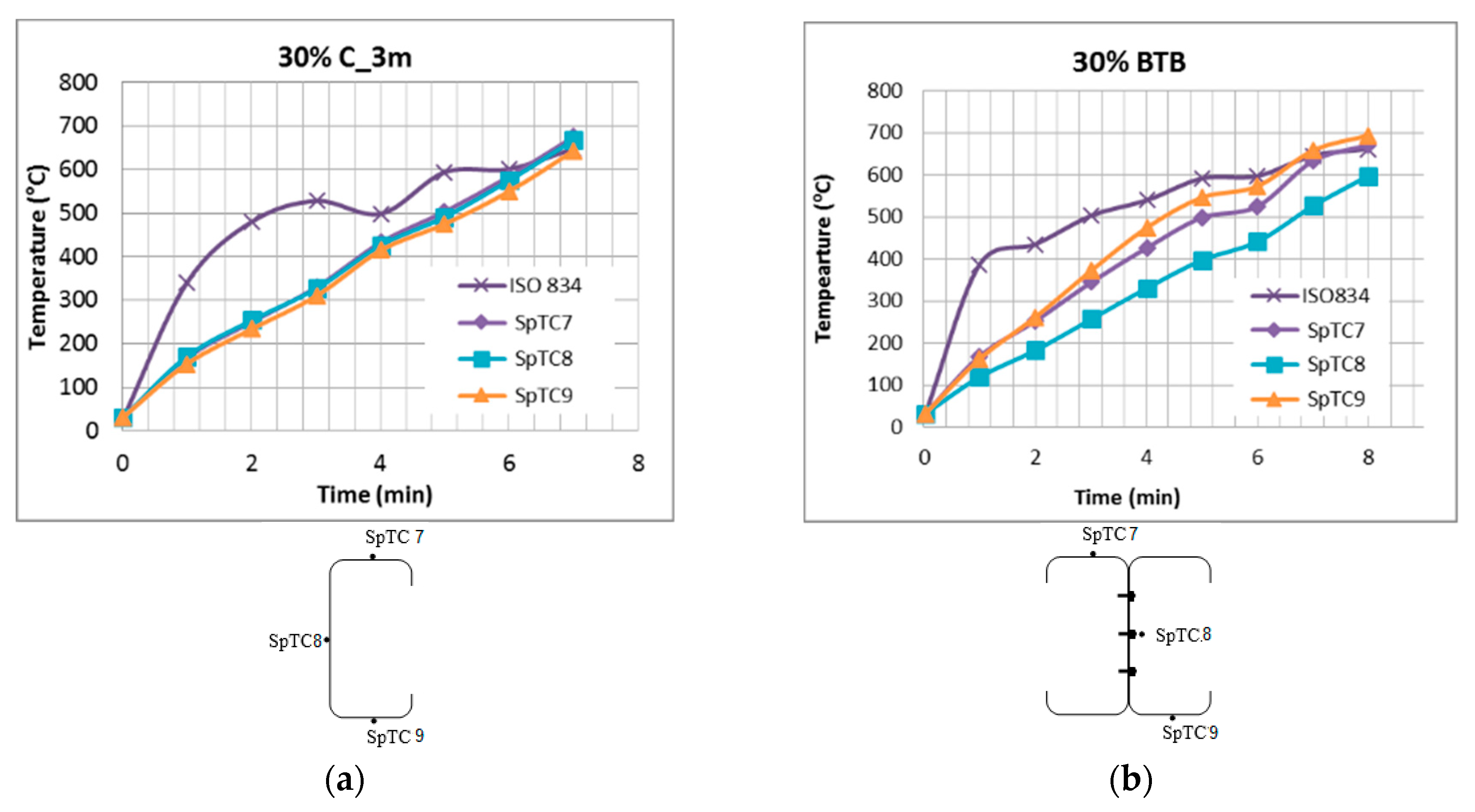
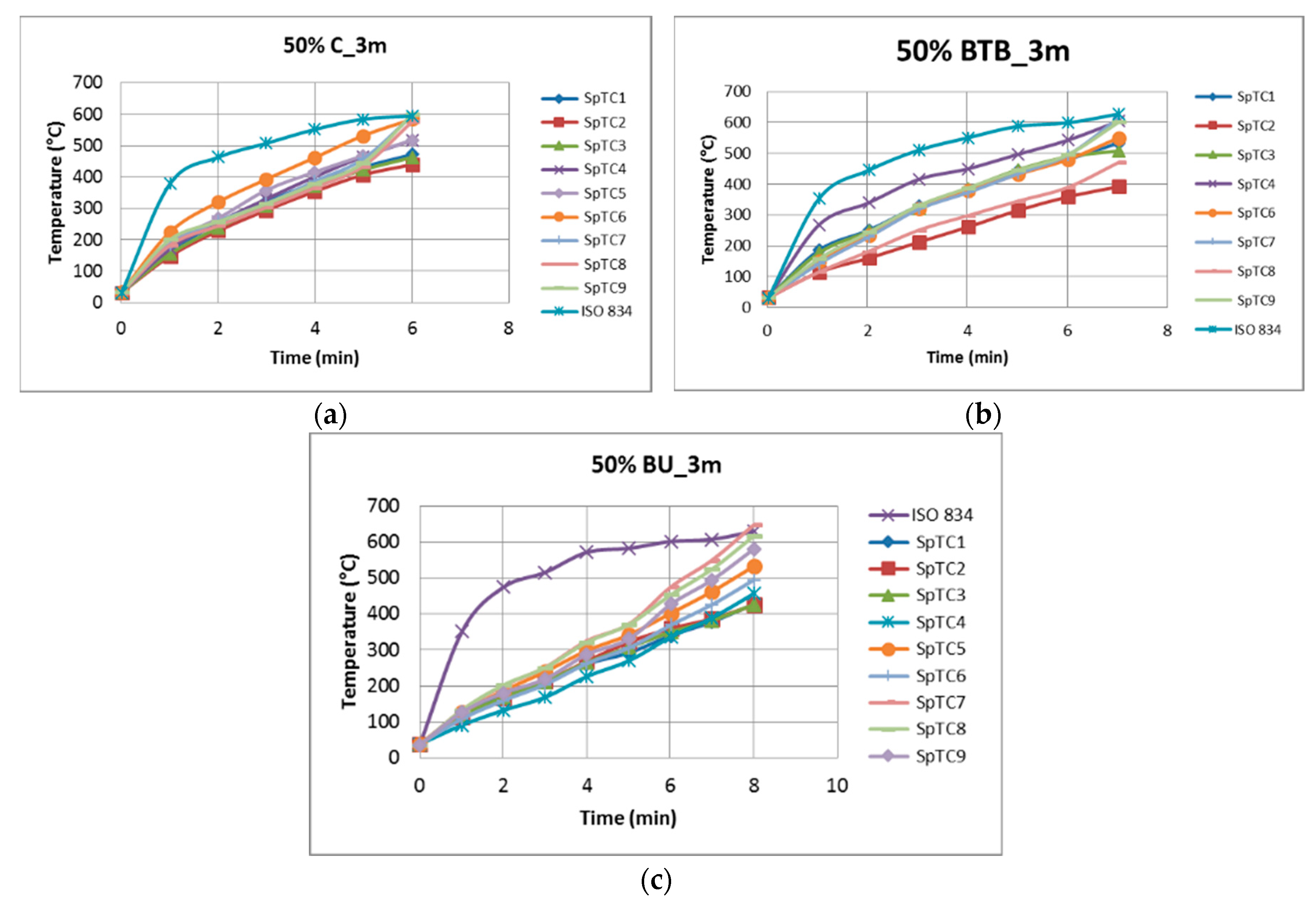
Figure 7 shows the typical temperature recorded during 50% load use for the channel, BTB, and BU column. The temperature variation at the web and flange of CFS is shown in
Figure 8. Generally, the analysis of mean temperature was done for each column by using a ratio according to the surface area in which the temperatures recorded multiplied by the area of the column surface, and divided by the total area of the column.
3. Experimental Results
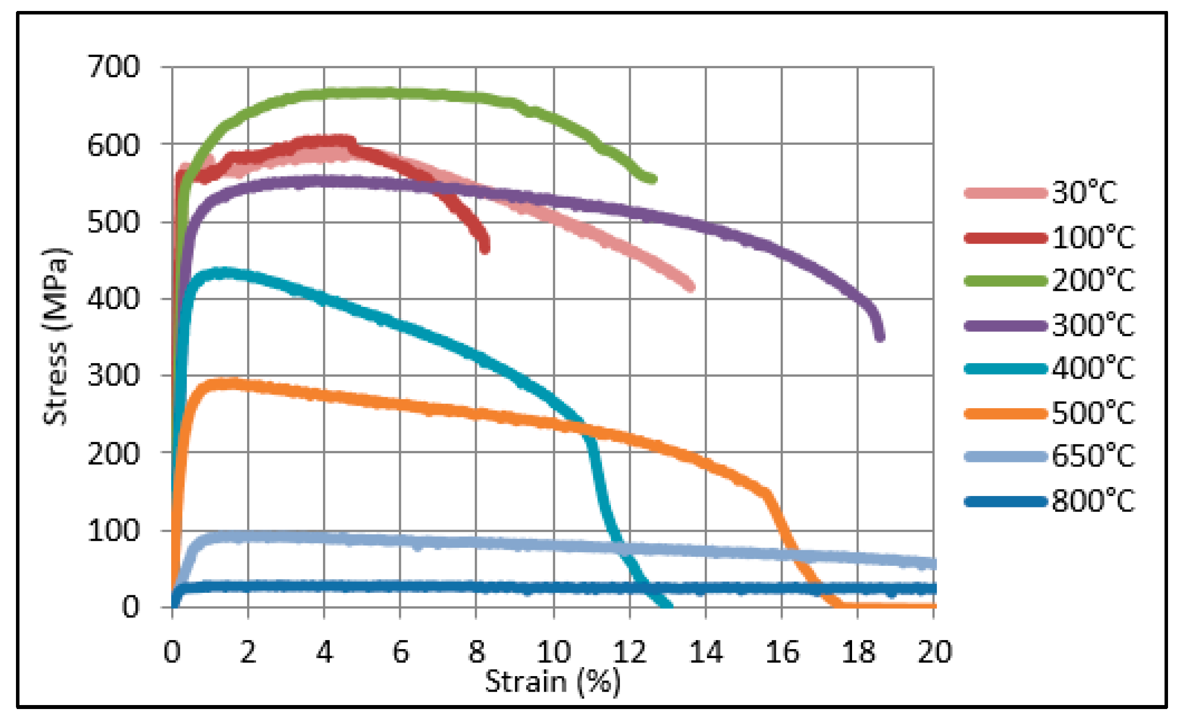
The stress–strain relationship at elevated temperature shows that CFS under different elevated high temperature has shown a change of less ductile to ductile behavior of material, as shown in
Figure 9. A clear linear elastic region followed by a defined yield plateau is observed in ambient and 100 °C stress–strain curves. Other temperatures result in undefined yield plateau. For stress–strain curves for temperatures up to 300 °C, the curve type is similar. The process of plastic flow with an increase in strength occurs until it reaches the ultimate strength, then the strength rapidly decreases. The CFS is less ductile at lower temperature. Beyond 300 °C and up to 500 °C, the strength reduces progressively. The material is considerably lost in the places that flow towards ultimate strength. The strength decreases aggressively after the ultimate stress. Temperatures 650 °C and 800 °C also lost in the plastic flow toward ultimate strength but it undergoes very slow strength drop after the ultimate strength and clear necking failure is observed. The CFS is highly ductile at high temperature.
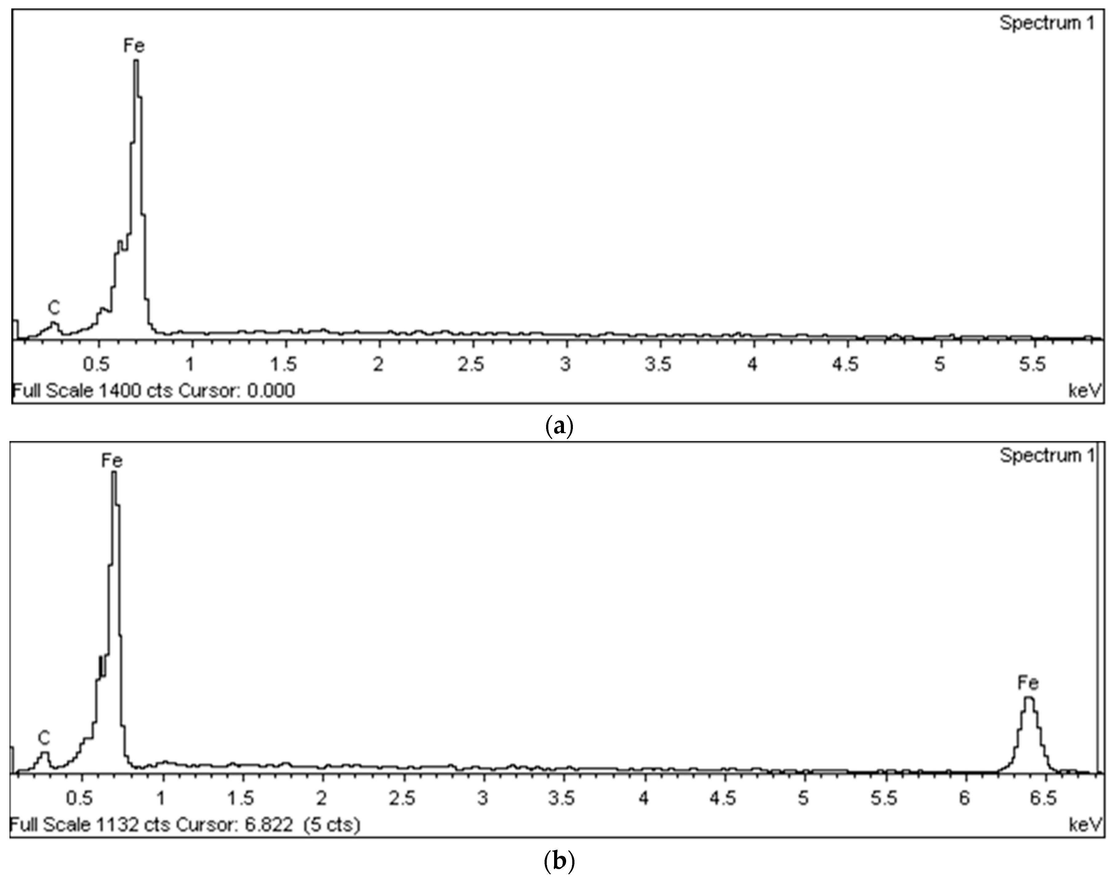
The chemical composition between ambient temperature and fire under 600 °C temperature is tested, and the result is shown in
Table 2. The EDX spectrum from the testing of the CFS was analyzed and shown in
Figure 10. The major element of the CFS is carbon, and iron is detected at ambient and 600 °C temperature. The carbon element is increased, and the iron element is decreased when the CFS is subjected to fire. The percentage difference of weight and atomic weight of carbon element is reported to be 23.53% and 21.51% when comparing between ambient and 600 °C temperature, respectively. Additionally, the iron element is reduced by approximately 0.86% of weight and 3.57% of atomic weight when CFS is subjected to fire under 600 °C temperature. Finally, the chemical composition of CFS is not significantly changed when subjected to fire conditions under 600 °C.
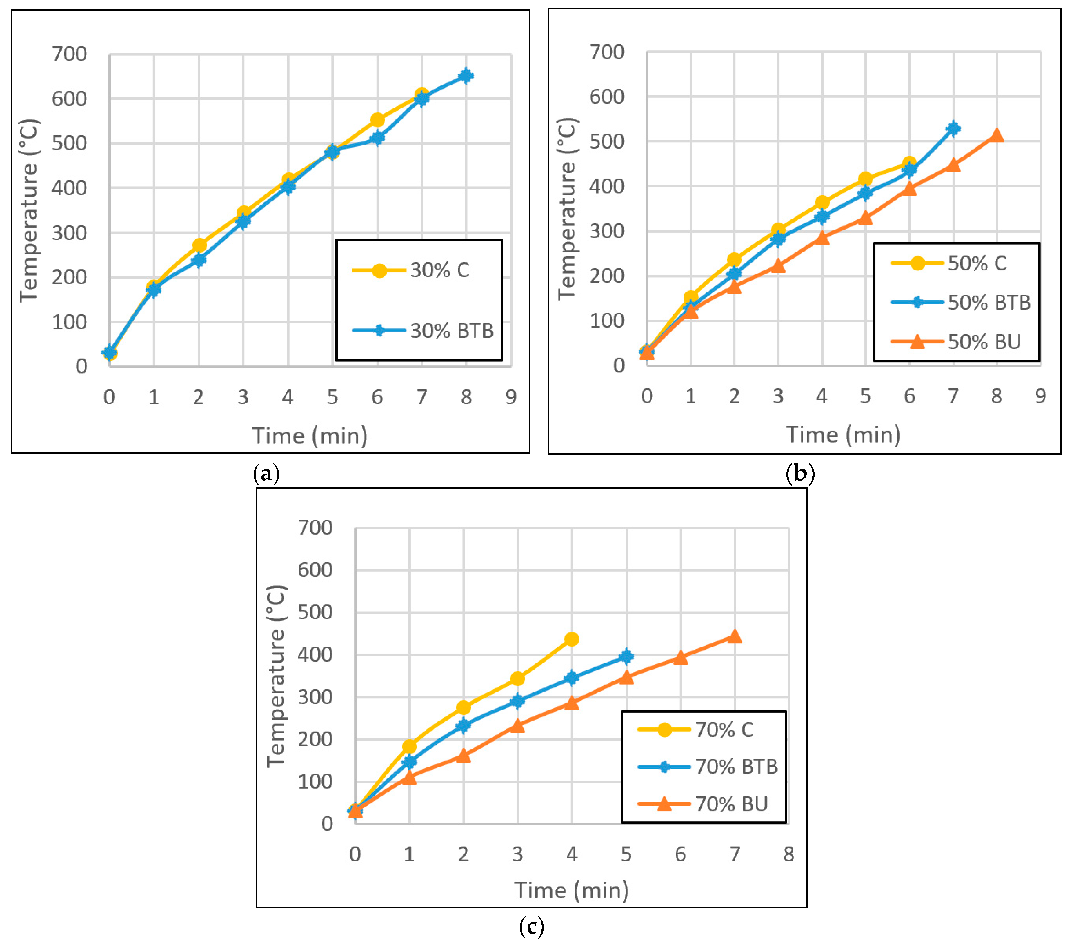
Column shape could have a significant effect on the temperature and failure time of a column. To analyze the effect, an analysis should be conducted against the degree of utilization.
Figure 11 shows the temperature–time curve of CFS columns. Both channel and BTB columns at 30% and 50% degree of utilization had similar temperature rises until failure, while BTB had slightly higher time and temperature. However, when the column was under 70% degree of utilization, the temperature rise differed for all column types. The channel column had a higher temperature rate followed by BTB and BU. There was a similarity for 30% and 50% load use for the channel and BTB columns because both columns were open sections; thus, their temperatures were higher as both sides of the columns were exposed to fire. In addition, the initial buckling of both columns was slightly similar because the columns were axially loaded. Hence, it can be said that buckling shape was the reason for the similar heating rates. However, initially, when a higher load was initially applied, the channel section experienced lateral distortion in the cross-section at mid-height, which may have caused the higher temperature. The BTB column still maintained a cross-section position in local and global buckling, due to the symmetrical cross-section along the column length. The BU showed a lower temperature rise because the inner side of the hollow column was cool. Hence, the temperature outside the BU needed to be balanced with the inside temperature, causing the delay in temperature rise. In addition, the BU column was a symmetrical section, and able to maintain the shape of buckling without the distortion mode in the cross-section.
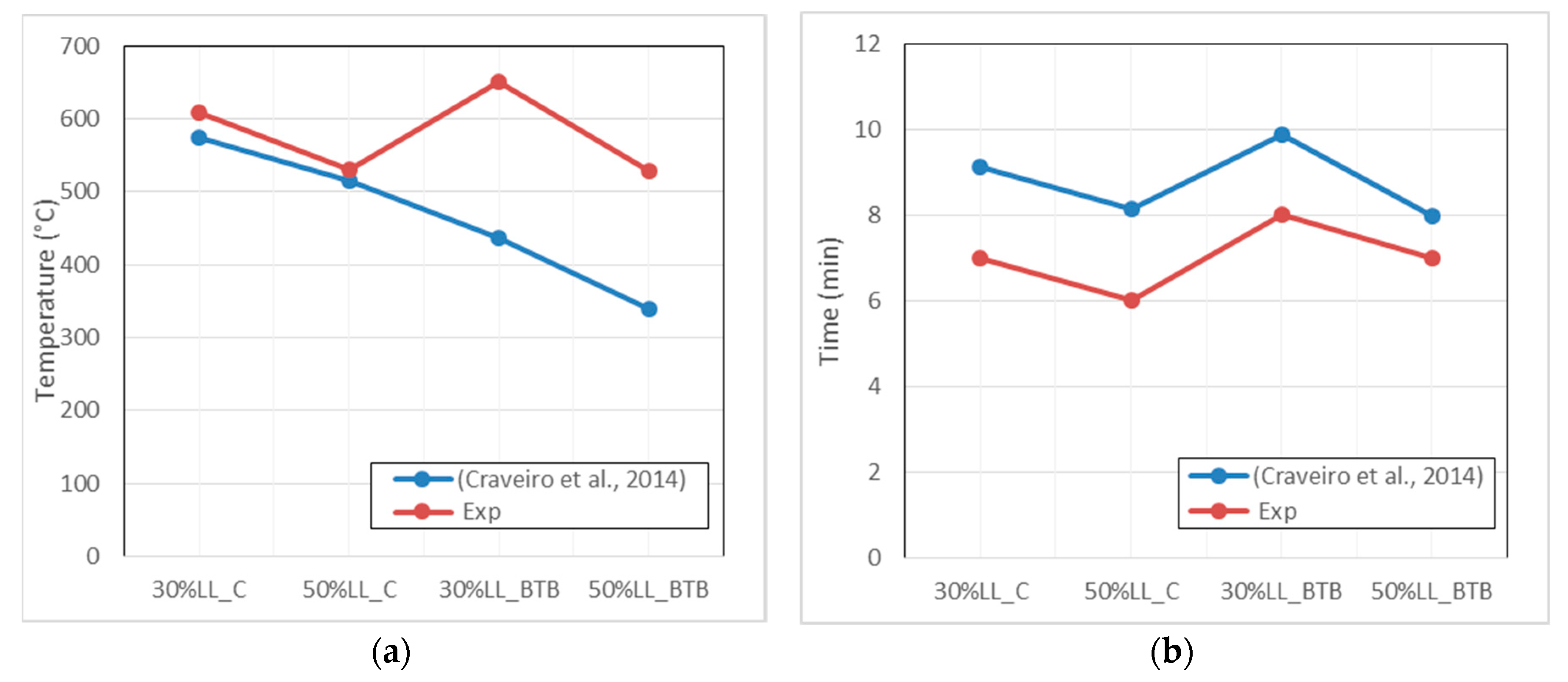
The maximum temperature was compared to the results from Craveiro et al. [
17], as shown in
Figure 12. The temperature of 30% and 50% degree of utilization for a CFS channel section has gained similar value. However, the BTB section results differed. In this study, the temperature for BTB was higher and almost similar to the channel column. The higher value of the temperature was achieved because the analysis of the column temperature found that the built-up column can withstand a longer time of exposure; hence the furnace was able to expose higher temperature to the column. Therefore, the surface temperature resulted in higher values before the column failed. The time recorded was shown with a similar pattern to the previous research.
The design strength of CFS column is based on the limiting time or temperature. According to EC3-1-2, the limiting temperature of CFS is 350 °C, which is much lower than the value gained from the experiment. Hence, the prediction can only be made by adapting the maximum temperature gain from the experiment, and calculating the predicted buckling force at that particular temperature. The material properties of CFS at high temperature is also adapted. Based on the calculation for CFS under critical temperature, buckling force was determined for CFS column results, as shown in
Table 3. Comparison of the proposed design buckling resistance with test results yielded a mean test divided by predicting resistance of 1.42 for CFS columns.
Further analysis was conducted to evaluate the suitability of the limiting temperature method of EN 1993-1-2:2005 applied for the CFS fire design.
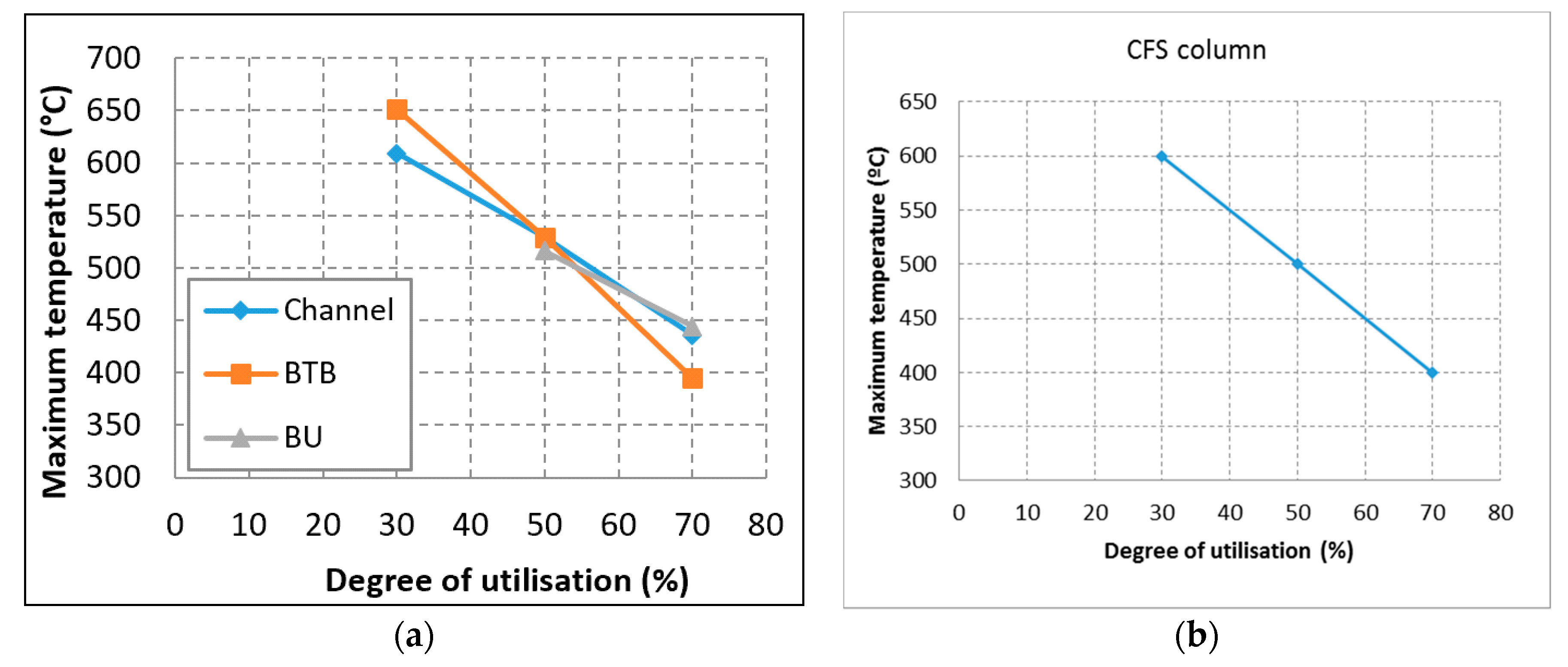
Figure 13a shows the maximum temperature and temperature at failure for the columns according to the degree of utilization. Generally, all columns experienced higher maximum temperatures at 30% degree of utilization and lower maximum temperatures at higher degrees of utilization. A negative linear relationship was found between the critical temperature and the degree of utilization.
The maximum temperature of different column shapes under 30% degree of utilization were compared. The BTB column had the highest value of temperature at 651 °C. Meanwhile, the channel column had a maximum temperature of 609.08 °C, a difference of about 42 °C compared with the BTB column. The BU column test was not conducted because a few tests produced unreliable results. However, the maximum temperature can be predicted according to the pattern of the channel column. The maximum temperatures of 50% degree of utilization were almost the same at 529.82 °C, 529 °C, and 515 °C for the channel, BTB, and BU columns, respectively. Finally, the 70% load use resulted in similar maximum temperatures of 435.68 °C and 443.77 °C for the channel and BU columns, respectively, and a slightly lower value of 395°C for BTB column, with a difference of around 45 °C compared with the other two column types. This proved that shape did not have any significant effects on critical temperature of CFS columns because the difference for each shape was small, which was less than 50 °C. According to this analysis of temperature in
Figure 13a, the critical temperature of CFS at different degrees of utilization can be determined. It is determined by the selection of the lowest maximum temperatures due to safety reasons to represent the critical temperatures of CFS at different degrees of use, i.e., 609.08 °C, 515 °C, and 395 °C. These values of temperature were plotted against the degree of utilization as represented in
Figure 13b. The higher the applied load—or, as used in this study, the higher the degree of utilization of the CFS columns—the greater the negative linear effect on their critical temperature. This behavior was the reason for the higher initial deformation, whether in vertical or lateral deformation of the column, at high degree of utilization [
17].
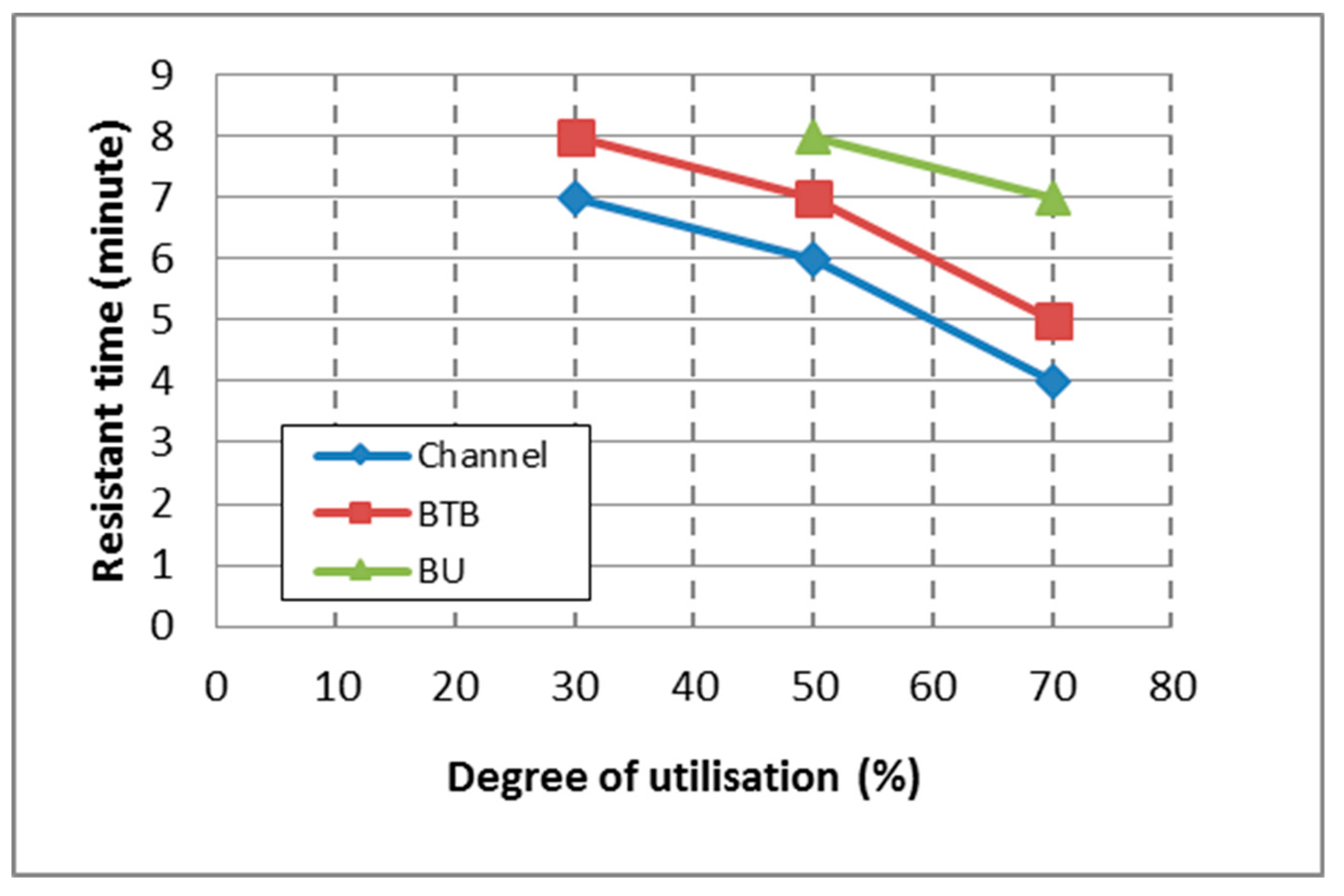
Resistance time was also analyzed based on the effect of different column shapes.
Figure 14 shows the effect of steel section type on fire resistance time under different degrees of use. Similar to the maximum temperatures of the columns, the resistance time was higher at 30% degree of utilization and lower at higher degrees of utilization. The critical time had a non-linear relationship with the degree of utilization. The BU column experienced higher resistance time of 8 and 7 minutes for 50% and 70% degree of utilization, respectively. Meanwhile, the channel column had the fastest resistance time of 7, 6, and 5 minutes for 30%, 50%, and 70% degree of utilization, respectively. The trend for the channel and BTB columns was similar to that of the BTB column, and differed by only one minute compared to the channel column for all degrees of use. The BU column was able to withstand the load longer before it failed. It allowed the temperature to rise in the column. The studied hollow BU column with a 2-mm wall thickness had 8 minutes of fire resistance under 50% load use. This proved that the hollow section had a better fire resistance compared to the open section. Previous research has shown that a steel column with a hollow section has better fire resistance. CFS hollow sections with thickness of 8 mm and 25 mm had fire resistance of 15 min and 30 min, respectively, whereas the open section had an even lower fire resistance time [
18]. The reason for the higher fire resistance time of the hollow section was that the air in the column was cooler, and had to be inside the stable air temperature before reaching the stable steel temperature. The steel wall had different inner and outer temperatures. The difference caused a delay of temperature rise for the steel column. Meanwhile, for the open sections, i.e., the BTB and channel columns, the fire was exposed to both sides of the steel wall. The temperature of the steel was constant on both sides, causing the steel temperature to reach the furnace temperature faster.
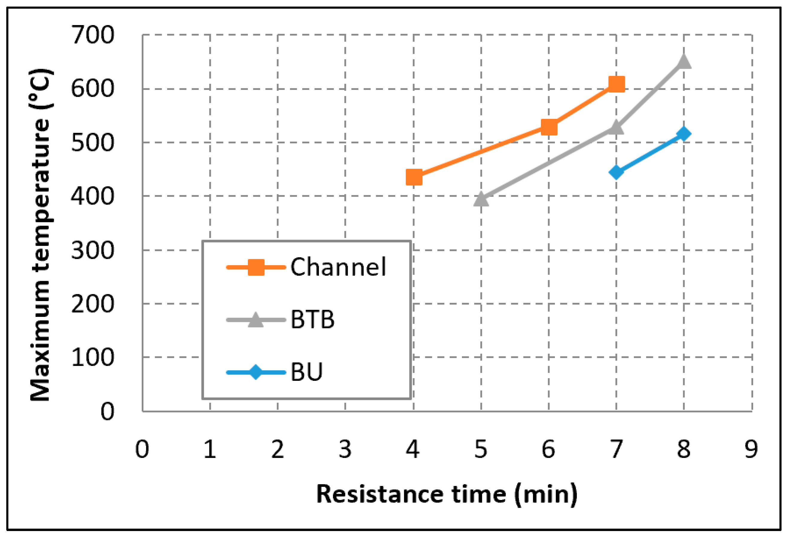
Figure 15 shows the relationship between the maximum temperature and the resistance time of the CFS columns. As time increases, the maximum temperature of the column also increases. 400 °C was considered to be the minimum limiting temperature of the column, and four minutes the minimum limiting time of the column.
As per the recommendation in EN 1993-1-2:2005, CFS was classified as a Class 4 cross-section. The constant limiting temperature was 350 °C and it was applied for all degrees of use. This value is too low and too conservative compared to the value of limiting temperature for 30% load level and high slenderness single-channel CFS fire design. Meanwhile, according to the load level and slenderness of the column for the built-up I-section, it may or may not be too conservative [
17]. It was concluded that a new methodology or simplified calculation technique for the limiting temperature method should consider the cross-section shape and slenderness [
17]. The finding of the temperature analysis found that the minimum limiting temperature was 400 °C. In addition, it was not constant for lower degrees of use where the maximum failure temperature could be higher.
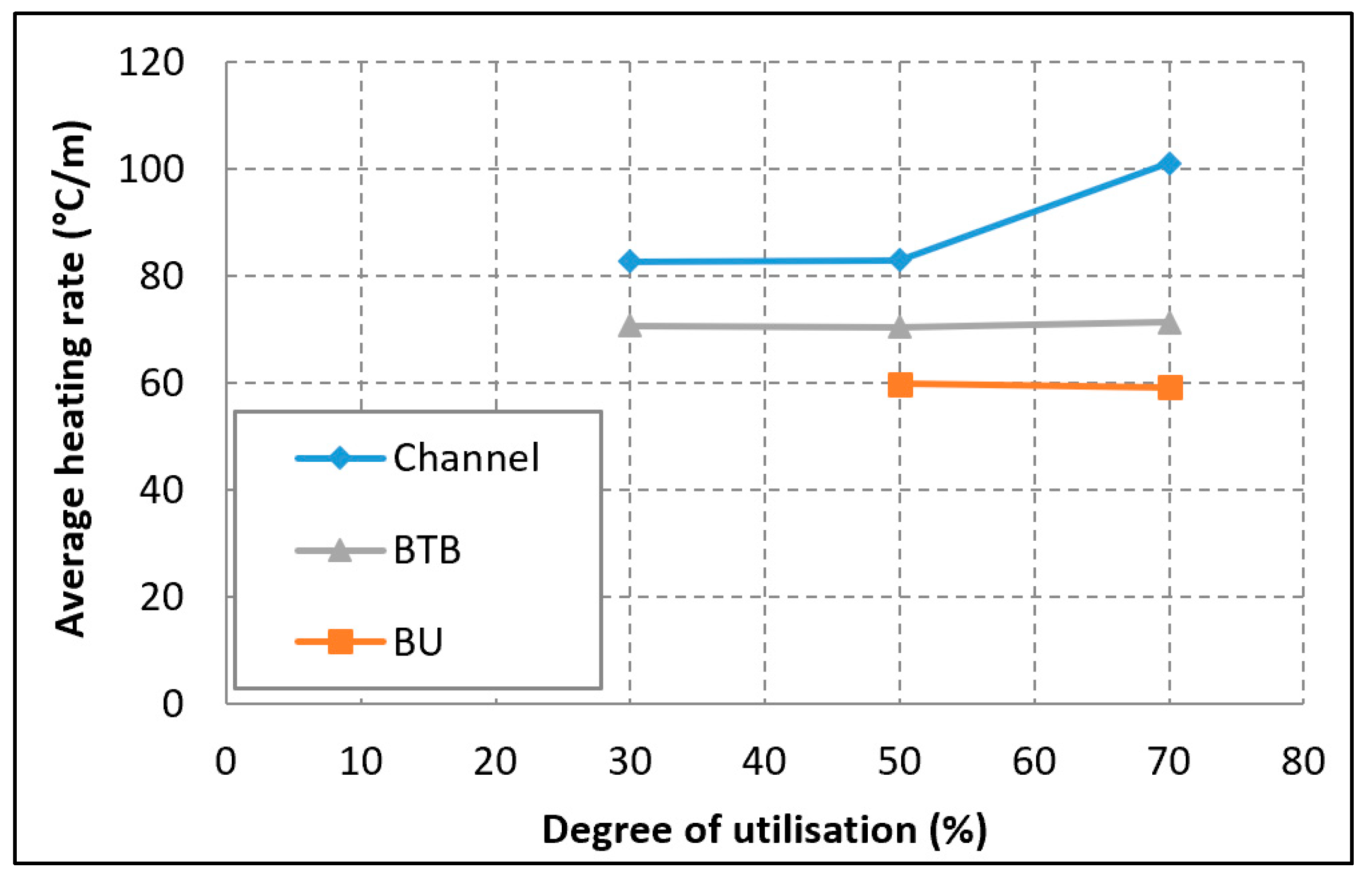
The variation of the average heating rate is shown in
Figure 16. The average heating rate shows how fast the column temperature rises when exposed to fire. The channel column had the fastest average heating rate followed by the BTB column, whereas the BU column had the slowest average heating rate. The thicker width of the column web and flanges resulted in a lower average heating rate for both BT and BU columns, respectively.
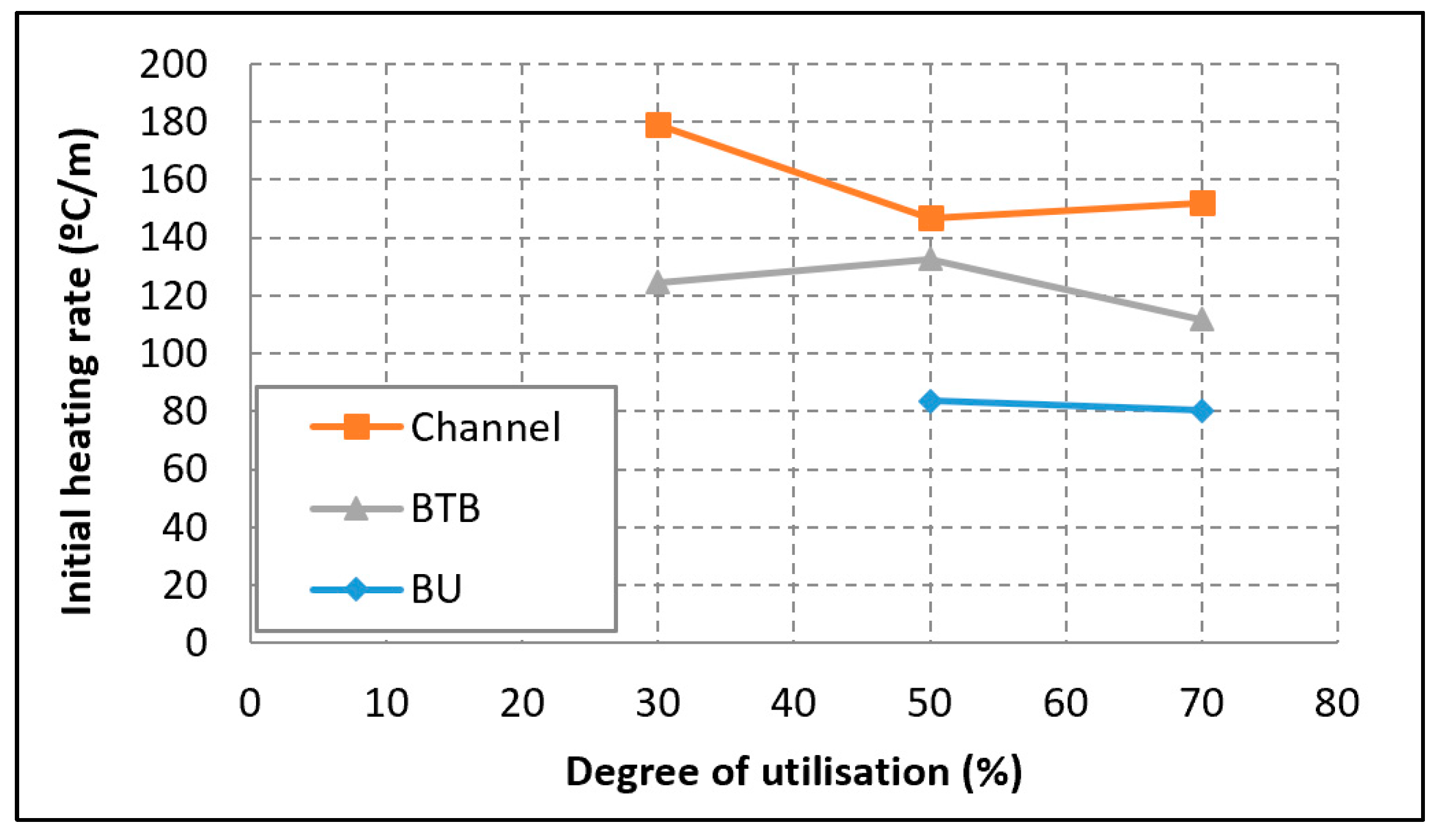
Figure 17 shows the initial heating rate of one minute of fire exposure.
The rate of temperature rise of the column greatly depended on the surface area of the member that was exposed to fire. It was affected by the “section factor” or “massivity factor”, Am/V, where A is the surface area exposed to heat flux and V is the volume of the member per unit length. The unit is m
−1. A low section factor will have a slower heating rate, and vice versa. The section factor values for the channel, BTB, and BU columns were 1.04 m
−1, 0.79 m
−1 and 0.39 m
−1, respectively.
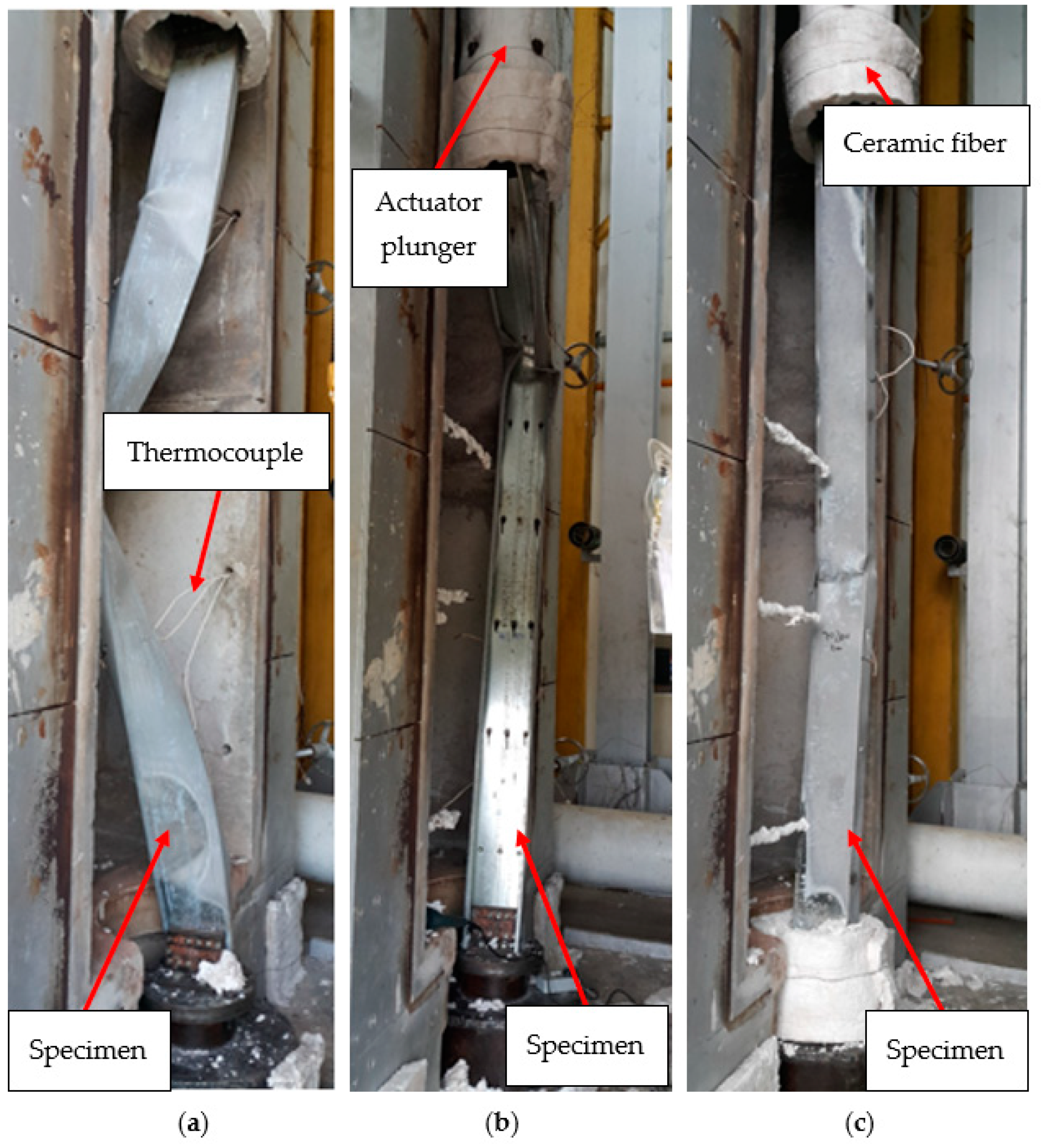
Figure 18 shows the typical column failure after exposure to fire. The load was applied by a hydraulic actuator and plunger located on top of the column. The support for the column was covered with ceramic fiber. It was covered to avoid support deformation due to fire. Generally, all columns fail due to a variety of modes of buckling.


