Article

Continuous Cooling Transformation Diagram, Microstructures, and Properties of the Simulated Coarse-Grain Heat-Affected Zone in a Low-Carbon Bainite E550 Steel

1
Key Laboratory for Anisotropy & Texture of Materials, Ministry of Education, Northeastern University, Shenyang 110819, China
2
School of Mechanical & Automobile Engineering, Qilu University of Technology (Shandong Academy of Sciences), Jinan 250353, China
3
School of Materials Science and Engineering, Northeastern University, Shenyang 110819, China
*
Authors to whom correspondence should be addressed.
Metals 2019, 9(9), 939; https://doi.org/10.3390/met9090939
Submission received: 26 July 2019 / Revised: 15 August 2019 / Accepted: 22 August 2019 / Published: 27 August 2019
(This article belongs to the Special Issue Advances in Structural Steel Research)

Abstract

:
In order to provide important guidance for controlling and obtaining the optimal microstructures and mechanical properties of a welded joint, the continuous cooling transformation diagram of a new low-carbon Nb-microalloyed bainite E550 steel in a simulated coarse-grain heat-affected zone (CGHAZ) has been constructed by thermal dilatation method in this paper. The welding thermal simulation experiments were conducted on a Gleeble-3800 thermo-mechanical simulator. The corresponding microstructure was observed by a LEICA DM2700M. The Vickers hardness (HV) and the impact toughness at −40 °C were measured according to the ASTM E384 standard and the ASTM E2298 standard, respectively. The experimental results may indicate that the intermediate temperature phase transformation of the whole bainite can occur in a wide range of cooling rates of 2–20 °C/s. In the scope of cooling rates 2–20 °C/s, the microstructure of the heat-affected zone (HAZ) mainly consists of lath bainite and granular bainite. Moreover, the proportion of lath bainite increased and granular bainite decreased as the cooling rate increasing. There is a spot of lath martensite in the microstructure of HAZ when the cooling rate is above 20 °C/s. The Vickers hardness increases gradually with the increasing of the cooling rate, and the maximum hardness is 323 HV10. When the cooling time from 800 °C to 500 °C (t8/5) is 5–15 s, it presents excellent −40 °C impact toughness (273–286 J) of the CGHAZ beyond the base material (163 J).

1. Introduction

At present, a series of new higher strength steel with 440–690 MPa is developing and applying to meet the needs of hull and offshore platform structure manufacturing [1]. Both hull and offshore platform structures are heavily welded with thick steel plates. They serve in the marine environment. Steel for those structures needs to have superior comprehensive properties, such as high strength, low-temperature impact toughness, seawater corrosion resistance, and good field weldability [2]. Studies have shown that a new type of ultra-low carbon bainite (ULCB) steel can meet those requirements of excellent comprehensive properties and more cost-effective [3,4,5]. The chemical composition design ideas of ULCB steel is a low carbon equivalent with additions of micro-alloying elements including molybdenum (Mo), niobium (Nb), titanium (Ti), nickel (Ni), and copper (Cu) [6,7,8]. On the one hand, the composition design of the low carbon equivalent of steel can improve the toughness and weldability; on the other hand, ultra-low carbon content inhibits the formation of cementite (Fe3C), thus avoiding the development of galvanic coupling between the ferrite (anode) and cementite (cathode) phases resulting in higher corrosion rates [9,10]. Meanwhile, ULCB steel was produced by applying reasonable thermo-mechanical controlled process (TMCP) and quenching and tempering (QT) technology [11,12,13]. Thus, the superior performance of ULCB steel can be obtained through solid solution strengthening, grains refining and precipitation strengthening, as well as through elevated hardenability and corresponding adjustment of the transformation microstructures [14,15]. However, the heating and cooling process of during steel welding is different from steel producing. The microstructure and performance of welded joint changes inevitably. As for the newly developed high-strength ULCB steel, it is a challenging task to ensure that the performance of the welded joint is not lower than that of the parent material. The welding heat-affected zone (HAZ), which suffers rapid heating and rapid cooling process, is the weak zone at the joint. The performance of the HAZ is greatly changed with the occurring of a very unbalanced continuous cooling transformation behavior and the arising of more complex abnormal microstructure. Therefore, it is of great significance to investigate the phase transition and microstructure of HAZ and further propose measures to control the phase change and organization. The solid-state phase transformation and final HAZ microstructure are affected by many factors, including steel composition, the steel rolling process, austenite grain coarsening characteristics, plate thickness, and the welding conditions [16,17]. For steel of certain composition, specification, and method of production, its transformation, microstructure, and properties of HAZ are mainly affected by welding thermal cycle parameters, such as heating rate, peak temperature, and welding heat input, especially the post-welding cooling rate [18,19,20]. To ensure the welding quality, welding efficiency, and cost reduction [21,22], the appropriate heat cycle parameters should be adopted in the offshore engineering industry. The continuous cooling transformation curve of the welding heat-affected zone (SH-CCT) is a helpful tool to display the phase transformation behavior of a material in the welding process [23,24]. It can be applied to optimize welding process parameters, relieve welding cracks, and lay down a standard of heat treatment after welding. In spite of the study of phase transformation behavior in CGHAZ becoming a key issue for research [25,26], SH-CCT diagrams vary with chemical composition of steels [27]. It is, therefore, necessary to understand the microstructural and microhardness changes within different sub-regions of the HAZ for different heat inputs in new high-strength microalloyed steel [28]. As a new type of steel, the SH-CCT of low-carbon bainite E550 steel in this paper has not been reported. This is the reason to establish the SH-CCT diagram of the specific E550 steel [29].
In this study, the expanding curves and SH-CCT of E550 steel were obtained by dilatometry and microscopic testing under different cooling rate. The transformation behavior, the evolution of microstructure, hardness, and low temperature impact toughness of CGHAZ are all studied. This study can provide references for understanding and controlling the microstructure and properties of such an ULCB steel during the welding process.

2. Materials and Methods

2.1. Experimental Material

The experimental material was cut from E550 platform steel which was produced by TMCP and QT. Its chemical composition is listed in Table 1 and the original microstructure mainly consisted of granular bainite (GB) and some lath bainite ferrite (LBF), as shown in Figure 1. This steel has the following mechanical properties: Rel = 624 MPa, Rm = 717 MPa, δ = 21%, AKV (−40 °C) ≥ 165 J, 240 HV10. Specimens were machined into three sizes: the ϕ 3 × 10 mm size specimens for measuring the Ac1 and Ac3 point, another samples as shown in Figure 2 for determining the SH-CCT, and the third sample of 11 × 11 × 60 mm3 was used to measure low-temperature impact toughness after welding thermal simulation and further machining.

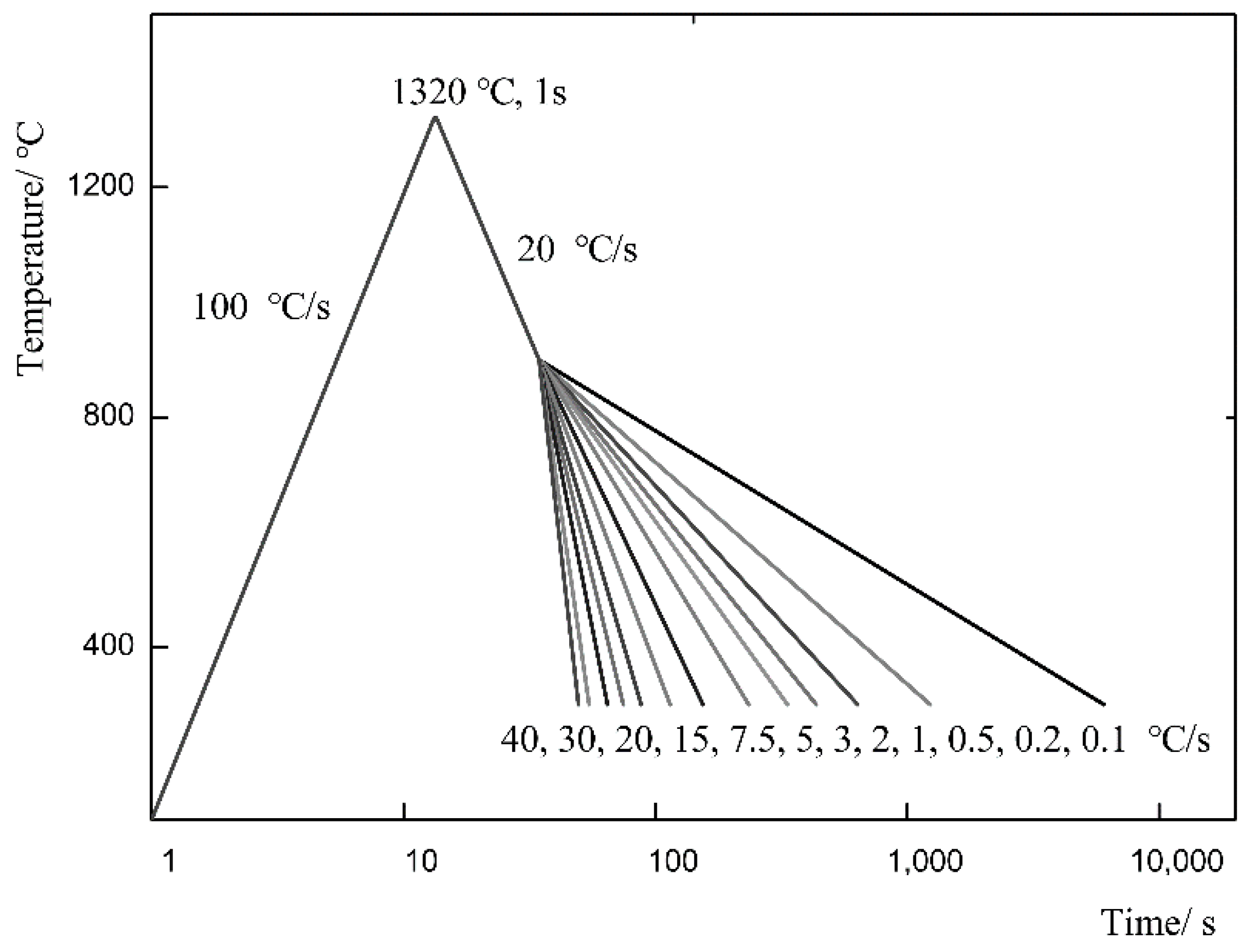
2.2. Experimental Method

The points of Ac1 and Ac3 were measured by a Formaster-FII dilatometer (Fuji Industry Inc, Tokyo, Japan): the sample was heated with heating rate 20 °C/s from room temperature to 250 °C, then heated to 1150 °C with a heating of 0.05 °C/s, after that, the critical point was determined according to the inflection point of the thermal expansion curve.
On a Gleeble-3800, specimens were heated at 100 °C/s from room temperature to the peak temperature (Tp1) of 1320 °C, holding for 1 s, then cooled to 900 °C at 20 °C/s, and finally cooled to room temperature at different cooling rates ranging from 0.1–40 °C/s, in which the cooling time from 800 °C to 500 °C (t8/5) is from 7.5–3000 s accordingly. The scheme for SH-CCT of experimental steel was shown in Figure 3. The cooling transformation temperature point was determined according to the inflection point of the cooling curve. The SH-CCT diagram of E550 steel was plotted according to the transformation points coupled with the microstructure characteristic and the hardness result at different cooling rates.
Specimens were heated at 100 °C/s from room temperature to the peak temperature 1320 °C, holding for 1 s, then cooled at different linear rates ranging from 2–60 °C/s, in which t8/5 is from 5 s to 150 s accordingly, as shown in Table 2. After that, specimens were machined into 10 × 10 × 55 mm3 standard Charpy V-Notch (CVN) samples and −40 °C impact toughness were measured according to the American Society for Testing Material (ASTM) E2298 standard. Three parallel samples are set at each observation point.
The observation of metallographic structures was made by a Leica DM2700M (Made in Leica Microsystems Inc., GER; Supplied by Leica Microsystems (Shanghai) Trading Co., Ltd., Changning, China). The Vickers hardness (HV) was measured by an HVS-50 (Laizhou Huayin Experimental Instrument Co., Ltd., Laizhou, China) under the condition of 98 N load and 15 s dwell time according to ASTM E384.

3. Results

3.1. Comparison of Austenitic Transformation Temperature of Test Steel under Different Heating Rate
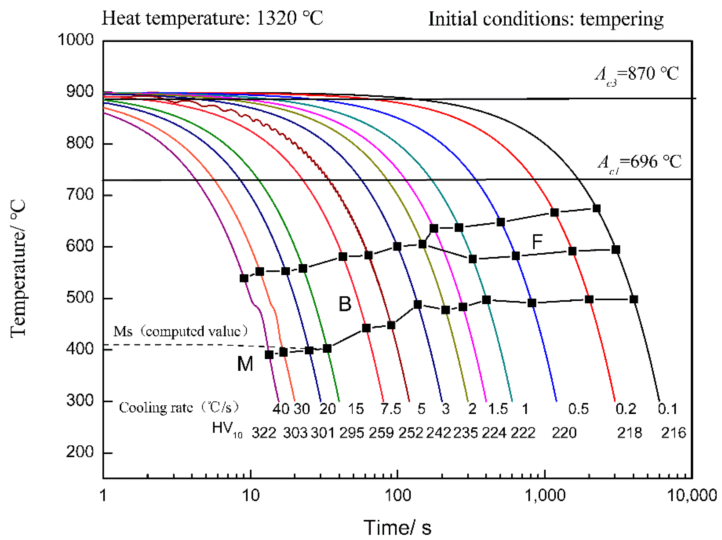
The αβ phase transformation critical temperatures of tested steel under different heating rates are presented in Figure 4. It can be seen from Figure 4, when the steel is heated at 0.05 °C/s, the critical temperature of Ac1 and Ac3 are 696 °C and 870 °C, respectively; when the steel is heated at 100 °C/s, the transformation of base metal bainite organization to austenite starts at 780 °C and ends at 920 °C. The start temperature of αβ phase transformation under the condition of rapid heating rate 100 °C/s is delayed about 84 °C compared to quasi-equilibrium state (when the heating rate is 0.05 °C/s) and the end temperature of the phase transition is delayed about 50 °C. The phase transformation range narrows 34 °C. Obviously, the austenitic temperature in simulated welding conditions is significantly higher than the austenitic temperature in the quasi-equilibrium state, and the phase transition time is shortened. This phenomenon will have an important effect on the subsequent cooling transformation behavior and products of austenite. The carbides in the steel lack sufficient time to fully dissolve under the condition of rapid heating. The concentration distribution of carbon and alloy elements in the austenite is uneven because of the atoms of carbon and alloy elements has insufficient time to diffuse. The corresponding carbon-poor zone and carbon-rich zone are formed [30]. The carbon-rich zone is more likely to form a carbon-rich M-A constituent in the subsequent cooling process. The amount, size, and distribution of M-A components have great influence on hardness and toughness.

3.2. SH-CCT Diagram

The SH-CCT diagram of tested E550 steel is presented in Figure 5. In the diagram, F is ferrite, B is bainite, and M is martensite. It can be seen that the cooling rate has an obvious effect on the αβ phase transformation temperatures. From Figure 5, the phase transformed into bainite completely can occur in a wide range of cooling rates in the range 2–20 °C/s. Moreover, the initial temperature of the bainite phase transition decreases as the cooling rate increases. This indicates that the steel can obtain a single bainite microstructure within a relatively wide heat input range which corresponds to the cooling rate. Furthermore, as the cooling rate increases, the bainite phase transition begins to decrease in temperature, the microstructure may be refined, and the performance may be improved. Here, it is worth noting that it is difficult hard to observe other types of phase transformation except the bainite transition in the expansion curve, but a small amount of martensite is found in the microstructure when the cooling rate surpasses 20 °C/s actually.
To further confirm the experimental results, the point of the bainite transformation starting temperature (Bs) and the point of martensite transformation starting temperature (Ms) of the experimental steel can be estimated according to Equations (1) and (2) [31,32]:
Bs   ( ° C ) = 745 110   ω ( C ) 59 ω ( M n ) 39 ω ( S i ) 68 ω ( C r ) 106 ω ( M o ) + 17 ω ( M n ) ω ( N i ) + 6 ω ( C r ) 2 + 29 ω ( M o ) 2
Ms ( K ) = 764.2 302.6 ω ( C ) 30.6 ω ( M n ) 16.4 ω ( N i ) 8.9 ω ( C r ) + 2.4 ω ( M o ) 11.3 ω ( Cu ) + 8.58 ω ( Co ) + 7.4 ω ( W ) 14.5 ω ( S i )
where, ω ( C ) , ω ( Mn ) , ω ( Si ) , ω ( C r ) , ω ( Mo ) , ω ( Ni ) , ω ( C u ) , ω ( C o ) , ω ( W ) represents the mass percentages of elements C, Mn, Si, Cr, Mo, Ni, Cu, Co, and W, respectively. We put the chemical composition of the experimental steel into Equations (1) and (2). The calculated Bs and Ms are about 613.6 °C and 412.2 °C, respectively. The estimated Bs is close to the experimental Bs, which is about 605 °C at a 2 °C/s cooling rate. Meanwhile, the calculated Ms also has a certain reference value.
When the steel is cooled with a cooling rate of 0.1–2 °C/s, proeutectoid ferrite comes into being. There are two distinct transitions which correspond to ferrite phase transformation and bainite phase transformation, respectively. Furthermore, the beginning temperature of the ferrite phase transition decreases with the increasing of the cooling rate. The finished temperature of the ferrite transformation is not clear in the cooling curve obtained by the experiment, however, it is found that ferrite and bainite coexist in the actual metallographic observation, so the ferrite phase transition temperature range and bainite phase transformation temperature range overlap in the corresponding SH-CCT diagram. Ferrite transformation is not complete. Bainite transformation has already begun.

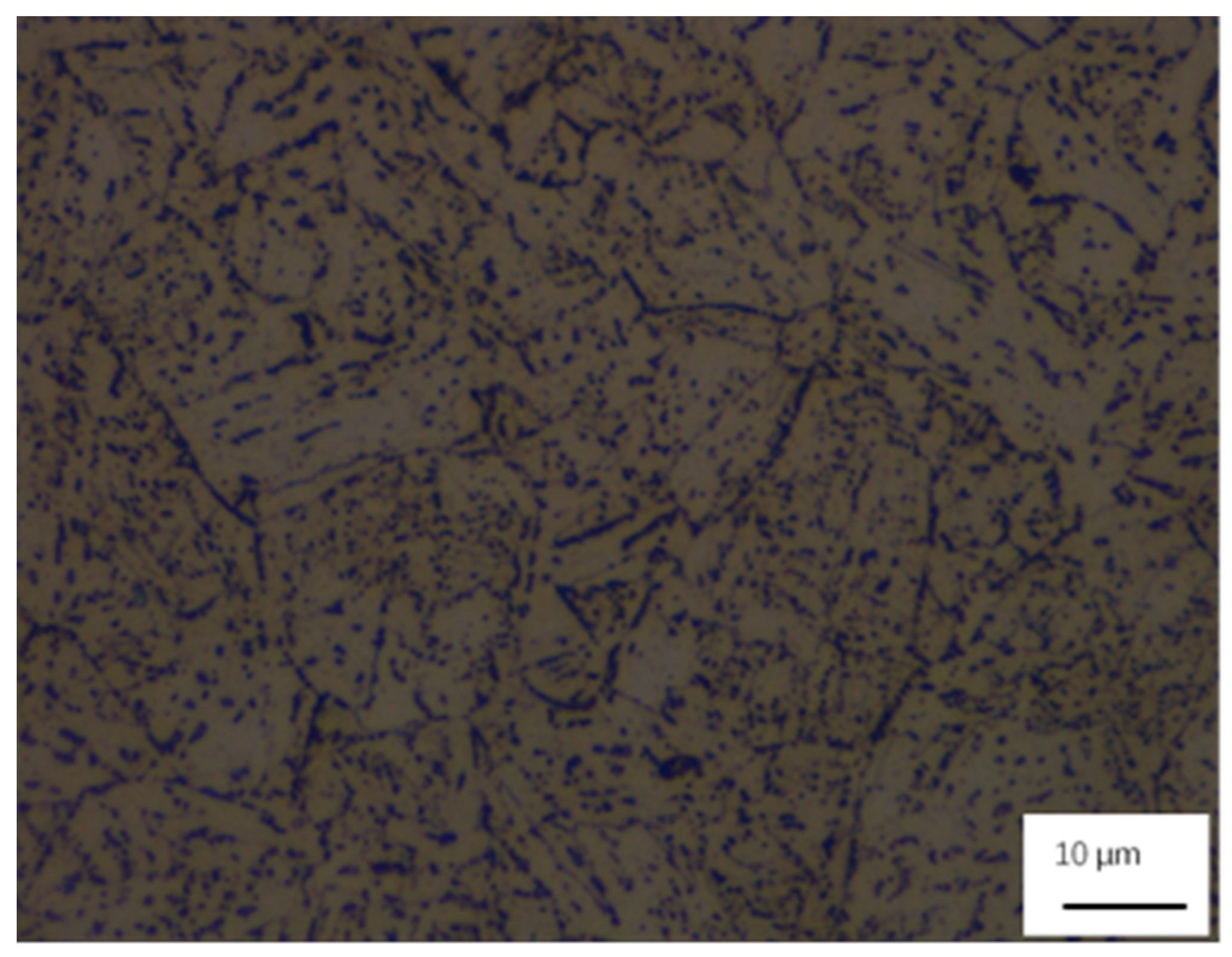
3.3. Microstructure in CGHAZ

Optical microstructures of the CGHAZ at each given cooling rate in the experiment are presented in Figure 6. It can be observed that when the steel is cooled at 0.1–1 °C/s (t8/5 = 3000–300 s), the microstructure is dominated by granular bainite and a portion of ferrite. When the cooling rate is 0.1 °C/s, the continuous phase transition product is GB and a portion is quasi-polygonal ferrite (QF) with a rough fuzzy boundary, the original austenite grain boundary contour is faintly discernible. There are small residual austenite residues in the matrix and a large amount of dark bead shape martensite-austenite (M-A) group at the boundary of the polygon ferrite or granular bainite, as shown in Figure 6a. With the increase of the cooling rate, the acicular ferrite emerges, and some of the original austenite grain boundary is visible, the content of ferrite was reduced and the content of GB increased, the shape of the tissue is changed from the elongated lath to short and thin lath, and the size of the M-A group with granular or column shape is finer, as shown in Figure 6b–d. When the steel is cooled at 2–20 °C/s (t8/5 = 150–15 s), as shown in Figure 6e–i, the microstructure is dominated by lath bainite and GB. This means that all the bainite tissues can be obtained over a wider range of cooling rates. It provides a wider range of heat input options for welding. Austenite grain boundaries can be observed to be very clear. In the interior of the original austenite grain, the grain is divided into different regions by lath bundles in different directions. Furthermore, with the increasing of the cooling rate, the content of granular bainite was reduced and the content of lath bainite increased, the size of lath inside the grain gets smaller as the length becomes shorter and width narrows. The faster the cooling rate, the finer the lath bundle. The fine M-A groups are distributed in a needle-like arrangement among the lath or among the lath bundle. When the steel is cooled at 40 °C/s, the main microstructure is the lath bainite and lath martensite, and there are large granulated carbides in the microstructure.
The above results show that the low-carbon bainite E550 steel austenite has strong stability in the cooling process. The transformation mechanism of bainite is not a simple polygonal ferrite boundary nucleation but a complex transitional phase transition. The bainite microstructure has complex and diverse transitional morphological characteristics.

3.4. Hardness and −40 °C Impact Toughness of CGHAZ

Figure 7 demonstrates the CGHAZ hardness and −40 °C impact toughness curves of the E550 steel under different cooling rates. It is evident that, in terms of hardness, the results are consistent for both the samples for the SH-CCT test and samples for the impact test despite their different shapes and sizes (Figure 7a,b). As the cooling time t8/5 increases, the cooling rate becomes slower and the hardness of the sample decreases gradually. When the t8/5 below 150 s, the CGHAZ hardness is significantly increased with the decreasing of cooling time t8/5, and the maximum hardness is 323 HV10 when the cooling rate is 40 °C/s; when t8/5 is above 150 s, the hardness values had little change, but the sample hardness is lower than the base metal hardness which is 240 HV10, in other words, there is a clear softening phenomenon. It should be pointed out that excessive hardening and softening in the HAZ may, respectively, make the steel potentially susceptible to cold cracking and ductile fracture [28].
As for impact toughness, when the time t8/5 is within 5–15 s, it shows excellent impact toughness (273–286 J) of the CGHAZ beyond the base material (163 J). However, when t8/5 exceeds 30 s, the Charpy energy values present a sharp decline trend, when t8/5 is within 60–150 s, impact toughness of CGHAZ (8–23 J) is much lower than that of the base material. It means that welding should not be carried out within the heat input range corresponding to the time scope (t8/5 is within 60–150 s).
Combined with the previous analysis, it can be seen that, when the cooling rates are about 20 °C/s (t8/5 is about 15 s), the optimum microstructure of the CGHAZ, which is a mixture of fine lath bainite and granular bainite, is expected to display an excellent balance between toughness and hardness.

4. Discussion

The microstructure and performance of the product phase transition are closely related to the chemical composition and phase transition behavior [19]. The tested low-carbon bainite E550 steel contains micro-alloying elements such as niobium (Nb) and molybdenum (Mo). The Mo–Nb combination makes the austenite more stable, and bainite transformation easily occurs, which can inhibit the formation of grain boundary ferrite, and acicular ferrite appears at the high transformation temperature. The bainite transition is a transitional phase transition. When the cooling rate is low, the phase transition temperature is high, namely, the transformation tends to occur via a diffuse mechanism. When the cooling rate increases, the phase transformation is apt to be controlled by the shear mechanism. Thus, the cooling rate changes from low to high, and the following microstructures will appear in the CGHAZ of E550 steel: Polygonal ferrite (PF) → QF → GB → BF → lath martensite (LM). Although from the SH-CCT diagram the transformation type is simple, the transition microstructure type is extremely rich, in fact, and there are different forms of the carbon-rich phase.
In addition, the properties, especially toughness, are affected by residual stresses. Welding residual stresses are formed owing to localized heating and cooling during welding. Locked-in residual stresses of HAZ is disadvantageous to the toughness of steel. The magnitudes of the residual stress depend on the austenite transformation temperature and the thermal shrinkage [33]. Low carbon concentration promotes the transition at a higher temperature than the martensite transition at a lower temperature. Thus, the stress associated with the phase transition is reduced in ULCB steel. This is one of the reasons why ULCB steel has better toughness in general.
The microstructure characteristics and residual stress are all affected by the cooling rate of the continuous cooling process. Accordingly, the microstructure and performance of steel have the characteristics of changing with the cooling rate.
As mentioned above, when the cooling rate is slow, such as 0.1 °C/s, the microstructure of the sample mainly consists of GB and partially of QF. Much of the retained austenite in the tissue and granular M/A group dispersed in the matrix of the ferrite. QF is formed at a higher temperature, and its formation mechanism is the massive transformation. At the interface of the new phase and the parent phase, the atoms diffuse for a short distance; the chemical composition of the new phase is the same as in the parent phase. The transformation of granular bainite belongs to the mixed transition mechanism of shear and diffusion, and its special microstructural morphology is related to its continuous cooling transformation and low carbon content. The continuous cooling transformation of granular bainite has occurred in a wide temperature range, making the ferrite morphology in the matrix irregular; the low carbon content makes the retained austenite size of the bainite subunit too small to observe, and the single bainite is difficult to recognize. When the cooling rate is slow, carbon atoms have plenty of time to diffuse from the α/γ interface frontier to the γ phase, as a result, the carbon content of the retained austenite is increased and stable carbon-rich austenite forms. Part of carbon-rich austenite would transform into high-carbon martensite during the following cooling process. Thus, granular M/A islands form. Compared with the uniform and fine matrix structure, the welding material formed coarse PF and GB grains because of the slow cooling rate. Moreover, the M/A group in the matrix has a larger size, so the properties are obviously softened.
When the cooling rate is 0.2–2 °C/s, the acicular ferrite is present, and the change of the cooling rate causes the variation of the relative ratio of the granular bainite and the ferrite. The proportion of ferrite reduced and the proportion of granular bainite increased with the increasing of the cooling rate. Meanwhile, the volume fraction of M/A also increased and the grain size decreased. This can be due to the increasing of the cooling rate making it difficult for carbon atoms in the austenite to diffuse and the carbon-rich austenite is small in scale; thus, the size of M/A is reduced.
When the steel is cooled at 2–20 °C/s (t8/5 = 150–15 s), the transformation product is dominated by lath bainite and granular bainite, especially when the cooling rate exceeds 15 °C/s, the microstructure of the welded coarse crystalline zone is dominated by thin parallel growth lath bainite. Thus, high hardness and high impact toughness obtained at high cooling rates is attributed to these factors: on the one hand, the rapid cooling rate contributes to the formation of lath bainite. The content of lath bainite with a high density dislocation rises with the increasing of the cooling rate, and the strength and hardness of lath bainite are higher than that of granular bainite; on the other hand, the microstructure becomes gradually fine with the lath length becoming shorter, and the width is narrowed with the increase of the cooling rate, and M-A is fined in lath bainite grain. When the steel is cooled at 40 °C/s, lath martensite in the tissue appears, so the hardness and impact toughness are higher. In addition, lath martensite has a self-tempering effect, and carbon nitride precipitation of niobium can prevent grain boundary migration to refine grains. All these are beneficial to increase the hardness and impact toughness.

5. Conclusions

In present study, through simulation of welding thermal cycles and observation of microstructures in the CGHAZ, the continuous cooling transformation behavior of the simulated CGHAZ was studied, and SH-CCT diagrams of the new E550 steel was constructed. The correlation between the microstructure and its properties was analyzed. The following conclusions can be drawn:
The start temperature of α → γ phase transformation under the condition of a rapid heating rate (100 °C/s) is delayed about 84 °C, and the end temperature of phase transformation is delayed about 50 °C compared to the quasi-equilibrium state (0.05 °C/s). This phenomenon has an important effect on the subsequent cooling transformation behavior and products of austenite.
The phase transforming into bainite completely can occur in a wide range of cooling rates of 2–20 °C/s. This provides a wider range of heat input options for welding.
When the cooling rate changes from low to high, the following microstructures will appear in the CGHAZ of the tested E550 steel: PF → QF → GB → BF → LM.
The hardness of the CGHAZ is improved with the decreasing of cooling time t8/5, the maximum hardness is 323 HV10 when the cooling rate is 40 °C/s; there is a clear softening phenomenon when t8/5 is above 150 s.
When the time t8/5 is 5–15 s, the −40 °C impact toughness of the CGHAZ (273–286 J) is greater than that of the base material (161 J); when t8/5 is among 60–150 s, impact toughness of CGHAZ (8–23 J) is much lower than that of the base material. This means that welding should not be carried out within the heat input range corresponding to the time scope (t8/5 is 60–150 s).
When the cooling rates are about 20 °C/s (t8/5 is about 15 s), the optimum microstructure of the CGHAZ, which is a mixture of fine lath bainite and granular bainite, is expected to display an excellent balance between toughness and hardness.

Author Contributions

Conceptualization: Y.Z. and C.-M.L.; methodology: Y.Z.; validation: Y.Z. and C.-M.L.; formal analysis: Y.Z.; writing–original draft preparation: Y.Z.; writing–review and editing: Y.Z. and C.-M.L.; visualization: Y.Z. and C.-M.L.; supervision: C.-M.L.; project administration: Y.Z.; funding acquisition: Y.Z.

Funding

This work was funded by the National Natural Science Foundation of China (51401112).

Conflicts of Interest

The authors declare no conflict of interest.

References

  1. Zhang, X.G.; Yang, C.F.; Shang, C.J. New Development of HSLA Steels in China. In HSLA Steels 2015, Microalloying 2015 & Offshore Engineering Steels 2015, Hang Zhou, China, 2015; The Chinese Society for Metals (CSM), Chinese Academy of Engineering (CAE), Eds.; Springer Nature: Basel, Switzerland, 2016; pp. 3–15. [Google Scholar] [CrossRef]
  2. Zhou, Y.L.; Chen, J.; Liu, Z.Y. Corrosion Behavior of Rusted 550 MPa Grade Offshore Platform Steel. J. Iron Steel Res. Int. 2013, 20, 66–73. [Google Scholar] [CrossRef]
  3. Zhao, Y.T.; Yang, S.W.; Shang, C.J.; Wang, X.M.; Liu, W.; He, X.L. The mechanical properties and corrosion behaviors of ultra-low carbon microalloying steel. Mater. Sci. Eng. A 2007, 454, 695–700. [Google Scholar] [CrossRef]
  4. Wang, Z.F.; Li, P.H.; Guan, Y.; Chen, Q.F.; Pu, S.K. The corrosion resistance of ultra-low carbon bainitic steel. Corros. Sci. 2009, 51, 954–961. [Google Scholar] [CrossRef]
  5. Chen, Y.; Hu, L.B.; Qiu, C.J.; Wang, Z.C. Effects of Carbon and Boron on Structure and Properties of Austenitic Stainless Steel Coatings Fabricated by Laser Remanufacturing. Steel Res. Int. 2019, 90, 1800473. [Google Scholar] [CrossRef]
  6. Cizek, P.; Wynne, B.P.; Davies, C.H.J.; Hodgson, P.D. The Effect of Simulated Thermomechanical Processing on the Transformation Behavior and Microstructure of a Low-Carbon Mo-Nb Linepipe Steel. Metal. Mater. Trans. A 2015, 46, 407–425. [Google Scholar] [CrossRef]
  7. He, X.L.; Shang, C.J.; Yang, S.W. High Performance Low-Carbon Bainite Steel: Composition, Process, Organization, Performance and Application (Chinese); Metallurgical Industry Press: Beijing, China, 2007. [Google Scholar]
  8. Chen, Y.L.; Chen, L.Q.; Zhou, X.J.; Zhao, Y.; Zha, X.W.; Zhu, F.C. Effect of Continuous Cooling Rate on Transformation Characteristic in Microalloyed Low Carbon Bainite Cryogenic Pressure Vessel Steel. Trans. Indian Inst. Met. 2016, 69, 817–821. [Google Scholar] [CrossRef]
  9. Katiyar, P.K.; Misra, S.; Mondal, K. Corrosion Behavior of Annealed Steels with Different Carbon Contents (0.002, 0.17, 0.43 and 0.7% C) in Freely Aerated 3.5% NaCl Solution. J. Mater. Eng. Perform. 2019, 28, 4041–4052. [Google Scholar] [CrossRef]
  10. Sun, F.; Li, X.; Cheng, X. Effects of Carbon Content and Microstructure on Corrosion Property of New Developed Steels in Acidic Salt Solutions. Acta Met. Sin. (Engl. Lett.) 2014, 27, 115–123. [Google Scholar] [CrossRef]
  11. Nie, Y.; Shang, C.J.; Song, X.; You, Y.; Li, C.; He, X.L. Properties and homogeneity of 550 MPa grade TMCP steel for ship hull. Int. J. Min. Met. Mater. 2010, 17, 179–184. [Google Scholar] [CrossRef]
  12. Wang, B.; Song, Y.L.; Wen, X.M.; Wang, H.X.; Liu, Q.Y. Effect of Nb, Mo and Ti on the Microstructures and Mechanical Properties of 700MPa Weathering Steel. J. Iron Steel Res. Int. 2011, 18, 300–305. [Google Scholar] [CrossRef]
  13. He, X.L.; Shang, C.J. Microstructure Fining Theory of Low- carbon Bainitic Steel. In Ultra-Fine Grained Steels; Weng, Y.Q., Ed.; Springer: Berlin/Heidelberg, Germany, 2009; p. 235. [Google Scholar] [CrossRef]
  14. Zhang, J.; Ding, H.; Wang, C.; Zhao, J.; Ding, T. Work hardening behaviors of a low carbon Nb-microalloyed Si–Mn quenching–partitioning steel with different cooling styles after partitioning. Mater. Sci. Eng. A 2013, 585, 132–138. [Google Scholar] [CrossRef]
  15. Wang, B.X.; Dong, F.Z.; Wang, Z.D.; Wang, G.D. Microstructure and Property of Mn-Nb-B Low Carbon Bainite High Strength Steel Under Ultra-fast Cooling. J. Mater. Eng. 2016, 44, 26–33. [Google Scholar] [CrossRef]
  16. Lan, L.Y.; Qiu, C.L.; Zhao, D.W.; Gao, X.H.; Du, L.X. Effect of reheat temperature on continuous cooling bainite transformation behavior in low carbon microalloyed steel. J. Mater. Sci. 2013, 48, 4356–4364. [Google Scholar] [CrossRef]
  17. Barbaro, F.; Zhu, Z.X.; Kuzmikova, L.; Li, H.J.; Jian, H. Weld HAZ properties in modern high strength niobium pipeline steels. In HSLA Steels 2015, Microalloying 2015 & Offshore Engineering Steels 2015, Hang Zhou, China, 2015; The Chinese Society for Metals (CSM), Chinese Academy of Engineering (CAE), Eds.; Springer Nature: Basel, Switzerland, 2016; p. 453. [Google Scholar] [CrossRef]
  18. Di, X.J.; Ji, S.X.; Cheng, F.J.; Wang, D.P.; Cao, J. Effect of cooling rate on microstructure, inclusions and mechanical properties of weld metal in simulated local dry underwater welding. Mater. Des. 2015, 88, 505–513. [Google Scholar] [CrossRef]
  19. Shi, Y.W.; Han, Z.X. Effect of weld thermal cycle on microstructure and fracture toughness of simulated heat-affected zone for an 800 MPa grade high strength low alloy steel. J. Mater. Process. Technol. 2008, 207, 30–39. [Google Scholar] [CrossRef]
  20. Moeinifar, S.; Kokabi, A.H.; Madaah Hosseini, H.R. Influence of peak temperature during simulation and real thermal cycles on microstructure and fracture properties of the reheated zones. Mater. Des. 2010, 31, 2948–2955. [Google Scholar] [CrossRef]
  21. Shi, Z.R.; Wang, R.Z.; Wang, Q.F.; Su, H.; Chai, F.; Yang, C.F. Microstructures and continuous cooling transformation of CGHAZ in E36 class V-N-Ti, V-Ti and Nb-Ti shipbuilding steels. In HSLA Steels 2015, Microalloying 2015 & Offshore Engineering Steels 2015, Hang Zhou, China, 2015; The Chinese Society for Metals (CSM), Chinese Academy of Engineering (CAE), Eds.; Springer Nature: Basel, Switzerland, 2016; p. 517. [Google Scholar] [CrossRef]
  22. Zhang, Y.Q.; Zhang, H.Q.; Li, L.F.; Liu, W.M. Effect of Heat Input on Microstructure and toughness of coarse grain heat affected zone in Nb microalloyed HSLA steels. J. Iron Steel Res. Int. 2009, 16, 73–80. [Google Scholar] [CrossRef]
  23. Fonda, R.W.; Spanos, G. Microstructural evolution in ultra-low-carbon steel weldments—Part I: Controlled thermal cycling and continuous cooling transformation diagram of the weld metal. Met. Mater. Trans. A 2000, 31, 2145–2153. [Google Scholar] [CrossRef]
  24. Harrison, P.L.; Farrar, R.A. Application of continuous cooling transformation diagrams for welding of steels. Mater. Rev. 1989, 34, 35–51. [Google Scholar] [CrossRef]
  25. Wang, H.H.; Qin, Z.P.; Wang, X.L.; Wei, R.; Wu, K.M.; Misra, D. Continuous cooling transformation behavior and impact toughness in heat-affected zone of Nb-containing fire-resistant steel. Met. Mater. Int. 2017, 23, 848–854. [Google Scholar] [CrossRef]
  26. Li, H.; Liang, J.L.; Feng, Y.L.; Huo, D.X. Microstructure transformation of X70 pipeline steel welding heat-affected zone. Rare Met. 2014, 33, 493–498. [Google Scholar] [CrossRef]
  27. Singh, M.P.; Arora, K.S.; Shajan, N.; Pandu, S.R.; Shome, M.; Kumar, R.; Shukla, D. Comparative analysis of continuous cooling transformation behaviour in CGHAZ of API X-80 and X-65 line pipe steels. J. Therm. Anal. Calorim. 2019, 137, 1155–1167. [Google Scholar] [CrossRef]
  28. Poorhaydari, K.; Ivey, D.G. Heat-affected zone property diagrams for a grade 100 microalloyed steel. Weld. World 2018, 62, 551–564. [Google Scholar] [CrossRef]
  29. Hu, M.J.; Wang, P.; Lin, W.P.; Wang, X.Y.; Ji, L.K. SH-CCT of High-Strain Pipeline Steel X80. Adv. Mater. Res. 2012, 472, 1179–1182. [Google Scholar] [CrossRef]
  30. Liu, Z.C.; Ren, H.P.; Song, Y.Q. Solid Metal Phase Transition Tutorial (Chinese); Metallurgical Industry Press: Beijing, China, 2003; Chapter 2; pp. 46–47. [Google Scholar]
  31. Wang, G.D.; Shang, C.J.; Liu, Z.Y. Steel for Marine Applications; Chemical Industry Press (Chinese): Beijing, China, 2017; Chapter 3; p. 77. [Google Scholar]
  32. Lee, Y.K. Empirical formula of isothermal bainite start temperature of steels. J. Mater. Sci. Lett. 2002, 21, 1253–1255. [Google Scholar] [CrossRef]
  33. Gannon, L.; Yi, L.; Pegg, N.; Smith, M. Effect of welding sequence on residual stress and distortion in flat-bar stiffened plates. Mar. Struct. 2010, 23, 385–404. [Google Scholar] [CrossRef]
Figure 1. Original microstructure of E550 (a grade of steel) steel.
Metals 09 00939 g001
Figure 2. Dimension of the sample for determining continuous cooling transformation diagram of the simulated coarse-grain heat-affected zone (SH-CCT.).
Metals 09 00939 g002
Figure 3. The scheme for the SH-CCT of experimental steel.
Metals 09 00939 g003
Figure 4. Curve of austenite transformation critical temperatures of tested steel at different heating rates.
Metals 09 00939 g004
Figure 5. SH-CCT diagram of the tested E550 steel.
Metals 09 00939 g005
Figure 6. Microstructures of simulated coarse-grain heat-affected zone (CGHAZ) at different cooling rates: (a) 0.1 °C/s; (b) 0.2 °C/s; (c) 0.5 °C/s; (d) 1 °C/s; (e) 1.5 °C/s; (f) 2 °C/s; (g) 3 °C/s; (h) 5 °C/s; (i) 7.5 °C/s; (j) 15 °C/s; (k) 20 °C/s and (l) 40 °C/s.
Metals 09 00939 g006
Figure 7. Effect of cooling time t8/5 after welding on the impact toughness and hardness. (a) Hardness of CGHAZ of samples for SH-CCT test (b) −40 °C impact toughness and hardness of CGHAZ of samples for impact testing (BM: base metal).
Metals 09 00939 g007
Table 1. Chemical composition of experimental steels (wt%).
SteelCSiMnPSNbNiCrMoTiCu
E5500.063 0.26 1.38 0.0081 0.0016 0.044 0.65 0.40 0.22 0.017 0.35
Table 2. Welding heat simulation parameters.
Heating Rate
(°C/S)
Tp1
(°C)
Holding Time
(s)
T8/5
(s)
100132015, 10, 15, 30, 60, 100, 150

