Article

Influence of Microstructural Morphology on Hydrogen Embrittlement in a Medium-Mn Steel Fe-12Mn-3Al-0.05C

1
Steel Institute (IEHK), RWTH Aachen University, Intzestraße 1, 52072 Aachen, Germany
2
IEK-2, Forschungszentrum Jülich, Wilhelm-Johnen-Straße, 52425 Jülich, Germany
*
Author to whom correspondence should be addressed.
Metals 2019, 9(9), 929; https://doi.org/10.3390/met9090929
Submission received: 24 June 2019 / Revised: 6 August 2019 / Accepted: 21 August 2019 / Published: 24 August 2019
(This article belongs to the Special Issue Physical Metallurgy of High Manganese Steels)

Abstract

:
The ultrafine-grained (UFG) duplex microstructure of medium-Mn steel consists of a considerable amount of austenite and ferrite/martensite, achieving an extraordinary balance of mechanical properties and alloying cost. In the present work, two heat treatment routes were performed on a cold-rolled medium-Mn steel Fe-12Mn-3Al-0.05C (wt.%) to achieve comparable mechanical properties with different microstructural morphologies. One heat treatment was merely austenite-reverted-transformation (ART) annealing and the other one was a successive combination of austenitization (AUS) and ART annealing. The distinct responses to hydrogen ingression were characterized and discussed. The UFG martensite colonies produced by the AUS + ART process were found to be detrimental to ductility regardless of the amount of hydrogen, which is likely attributed to the reduced lattice bonding strength according to the H-enhanced decohesion (HEDE) mechanism. With an increase in the hydrogen amount, the mixed microstructure (granular + lamellar) in the ART specimen revealed a clear embrittlement transition with the possible contribution of HEDE and H-enhanced localized plasticity (HELP) mechanisms.

1. Introduction

A tremendous number of studies have focused on medium-Mn steels (MMnS) due to their excellent combination of mechanical properties and production cost as well as the understanding of complex deformation mechanisms and microstructure-property relationships [1,2,3,4,5,6,7,8]. By austenite-reverted-transformation (ART) annealing, medium-Mn steels often display ultrafine-grained (UFG) austenite-ferrite/martensite duplex microstructures [5,6]. The reverted austenite contributes to complex deformation mechanisms, enhancing the mechanical performance in MMnS. Deformation-induced martensitic phase transformation, the transformation-induced-plasticity (TRIP) effect, was reported to eliminate the localized deformation behavior in UFG microstructures and impede dislocation motion, resulting in considerably high ductility and work-hardening rate [1,2]. More recently, deformation-induced twinning was found in MMnS with a manganese content of 6 to 12 wt% after the α’-martensite formation, which was referred to as a medium-Mn twinning-induced-plasticity (TWIP) + TRIP steel [3,4]. Tailoring the mechanical properties by modifying the microstructure has also been intensively studied, involving the influences of intercritical annealing temperature [9,10,11], intercritical annealing time [10,12] and alloying elements [13,14,15].
Hydrogen embrittlement (HE) resistance is an important criterion for modern high-strength steels applied in the automobile industry, energy industry, aerospace industry and chemistry industry. The ferrite/martensite phase is considered to be vulnerable to hydrogen ingression, which contributes to the severe level of HE [16,17,18,19,20]. The austenite, as a critical phase in MMnS to improve mechanical performance, was reported to trap the hydrogen atoms effectively and leave the absorbed hydrogen in a more activated state, resulting in brittle fracture by the localized TRIP effect [16,17,19]. Han et al. [18] investigated the HE behavior in cold-rolled and hot-rolled Fe-7Mn-0.1C steel, correlating the contributions of well-established HE mechanisms, such as hydrogen-enhanced decohesion (HEDE) [21,22,23,24] and hydrogen-enhanced localized plasticity (HELP) [21,22,25,26] with microstructural features. The lamellar microstructure was found to be sensitive to hydrogen ingression compared to the granular one [18]. Most recently, Jeong et al. [20] argued that the lath-type austenite had a beneficial effect on relieving the hydrogen susceptibility compared with the equiaxed one due to the obstructed migration of hydrogen, which was contrary to the results of Han et al. [18].
The interaction between hydrogen and microstructural features has been studied in different steel grades [27,28,29]. However, little systematic work has been done to investigate the influences of microstructural morphology on HE susceptibility in MMnS, excluding the divergences in austenite fraction and mechanical properties. In the present work, by designing heat treatment, two different microstructures were produced and revealed comparable mechanical properties and austenite fraction. The effects of microstructural features on HE were investigated from the perspectives of hydrogen absorption and hydrogen-induced fracture modes. With a comprehensive understanding of the hydrogen–microstructure relation, we could design high-performance MMnS with superior HE resistance that can be applied for industry in the near future.

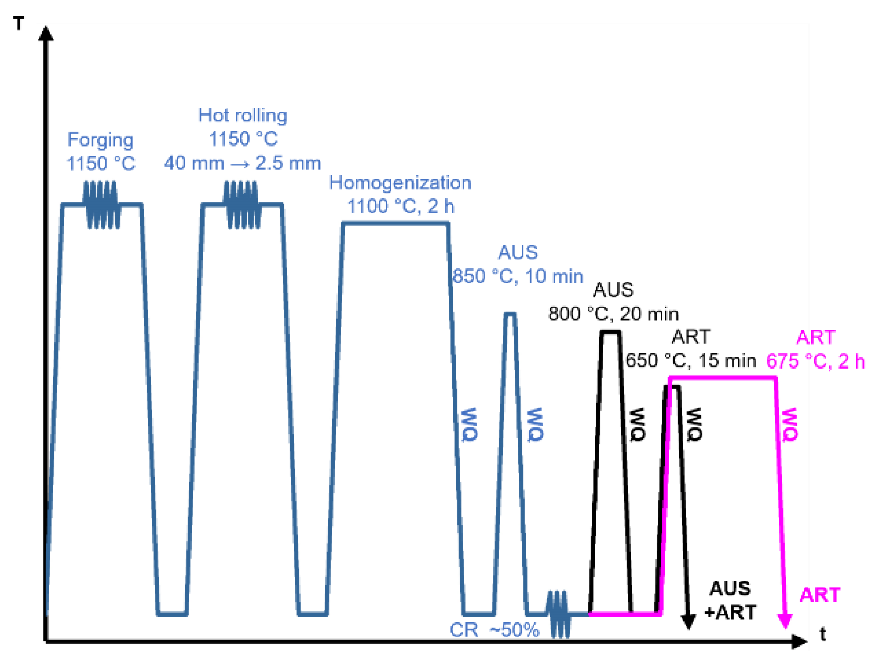
2. Materials and Methods

The chemical composition of the investigated medium-Mn steel Fe-12Mn-3Al-0.05C is given in Table 1. The 80 kg laboratory-melt alloy was cast into a 140 mm × 140 mm × 500 mm ingot in an ALD vacuum induction furnace (ALD Vacuum Tech. GmbH, Hanau, Germany), followed by hot forging to a bar with a cross section of 160 mm × 40 mm at 1150 °C. The thickness of the bar was finally reduced from 40 mm to 2.5 mm by hot rolling with reheating between passes. The material was subsequently homogenized at 1100 °C for 2 h to dissolve micro-segregations, followed by water quenching. The material was subsequently austenitized at 850 °C for 10 min and cold rolled with a reduction in thickness of 50% to the final sheet thickness of 1.25 mm. Two different heat treatment routes were selected to generate different microstructures with comparable mechanical properties by screening tests. A step of austenitization was applied to alter the initial microstructure, which was decisive to an as-annealed microstructure [7]. The cold-rolled specimen was austenitized at 800 °C for 20 min and then ART annealed at 650 °C for 15 min and termed AUS + ART. The other group of specimens were ART annealed at 675 °C for 2 h and denoted as ART. Figure 1 schematically shows the thermal cycles.
For hydrogen charging, the specimens were ground with SiC paper up to 2000 grit and polished with 3 µm diamond suspension. Specimens were subsequently hydrogen-charged for 2, 8 and 24 h, using the cathodic hydrogen-charging method. The specimens were subject to slow strain rate tensile tests (SSRT) immediately after hydrogen charging, using the tensile machine produced by Fritz Fackert KG (Moers, Germany) with a maximum load of 30 kN. The displacement speed of the crosshead was fixed at 2.5 × 10⁻⁵ mm/s, corresponding to an initial strain rate of 10−6 s−1. The fractured specimens were stored in a liquid nitrogen atmosphere before hydrogen measurement. The hydrogen content was measured by thermal desorption analysis (TDA) at the Welding and Joining Institute (ISF) of the RWTH Aachen University. The temperature range for measurement was from room temperature to 800 °C with a heating rate of 20 °C/min. The application of an external diffusible hydrogen module enabled the detection and analysis of both interstitial hydrogen and trapped hydrogen.
The inspection of fracture surfaces was carried out using a ZEISS DSM 982 scanning electron microscope (SEM) (Carl Zeiss Microscopy GmbH, Jena, Germany) with an acceleration voltage of 15 kV. For electron backscatter diffraction (EBSD) measurements, the specimens were ground with SiC paper up to 4000 grit and subsequently polished using 3 µm, 1 µm diamond suspension. Electropolishing was then performed at 28 V for 20 s using an electrolyte containing 700 mL ethanol (C2H5OH), 100 mL butyl glycol (C6H14O2), and 78 mL perchloric acid (60%, HClO4). EBSD measurements were performed with an acceleration voltage of 10 kV and a step size of 50 nm. The working distance was between 18 mm and 24 mm. A post-processing routine employing the HKL Channel 5 software (version 5.12j, Oxford Instruments, Abingdon-on-Thames, UK) was utilized, as well as the MATLAB-based MTEX toolbox [30,31].
Quantitative analysis on the amount of austenite and its mechanical stability was carried out using synchrotron X-ray diffraction (SYXRD) data, performed at beamline P02.1, PETRA III in Deutsches Elektronen-Synchrotron (DESY) center (Bahrenfeld, Hamburg, Germany). The measurement was operated with high beamline energy of 60 keV and a fixed wavelength of ~0.207 Å. The collected two-dimensional diffraction patterns were converted into intensity versus 2θ data by Fit2D software [32] and further analyzed using Rietveld refinement [33] by Material Analysis Using Diffraction (MAUD) software V 2.8.

3. Results

3.1. Microstructure

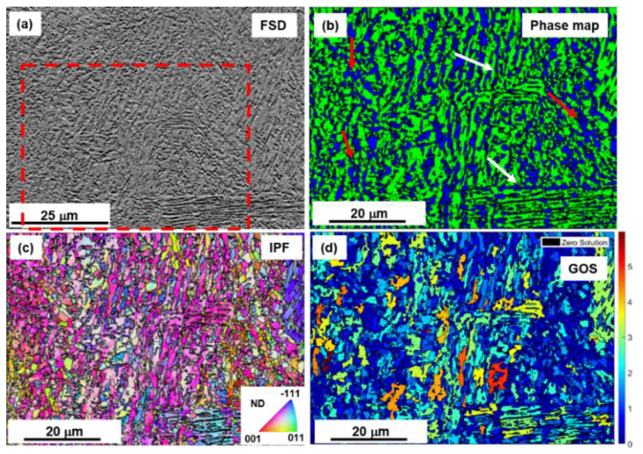
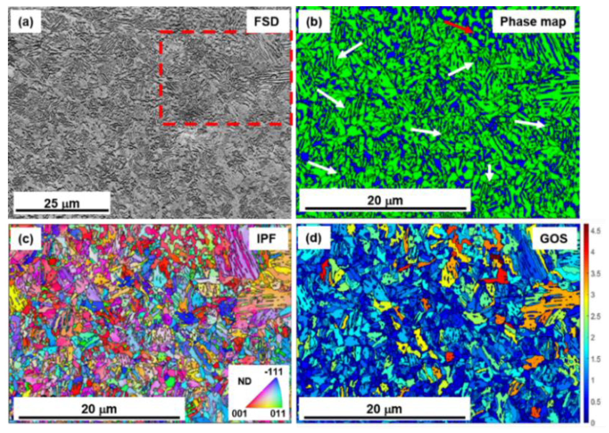
3.1.1. Electron Backscatter Diffraction (EBSD) Analysis of Microstructure

EBSD measurements were employed to characterize the phase distribution, the orientation distribution, and the misorientation. Figure 2a shows the forescatter diode (FSD) image of the ART specimen to highlight the UFG microstructure. Figure 2b shows that the austenite (blue area) had two main locations, between the martensite laths (green area) and in the globular-grain region. The red arrows mark the region with fine-grained globular structure, while the white arrows indicate the lamellar structure. The length of the lamellae ranged from 10 to 20 μm with a lamellar spacing of about 0.8 µm and the grain size of the fine-grained globular structure was around 1.5 μm. The inverse pole figure (IPF) of the ART specimen (Figure 2c) highlighted that the majority of deformed lamellar martensite showed orientations close to the <112>||ND-fiber (ND: normal direction), which denoted the retainment of cold-deformed microstructure. The grain orientation spread (GOS) figure (Figure 2d) shows that the globular austenite grains, as identified by the phase map, displayed low GOS values below 1, which is usual for recrystallized grains [34].
Figure 3a shows the FSD image of the AUS + ART specimen, with an indication of a further analysed area. Figure 3b exhibits the initial microstructure of AUS + ART specimen, which consisted of an ultrafine-grained lamellar structure and globular structure. The red arrows mark the region with ultrafine-grained globular structure, while the white arrows indicate the ultrafine-grained lamellar structure. During the step of austenitization, the deformed microstructure was fully eliminated and replaced by quenched martensite. The size of martensite packages ranged from 1 to 5 μm, the size of globular grains went down to 1 μm after subsequent ART annealing as a result of the competition between austenite reversion and martensite recrystallization. Unlike the ART specimen, AUS + ART specimen did not show a preferred orientation but revealed random orientation in IPF (Figure 3c). As shown in the GOS figure (Figure 3d), the ultrafine-grained martensite colonies manifested a low grain orientation spread, which indicates that they were recrystallized during intercritical annealing. The volume fraction of austenite determined from the EBSD measurement lacked accuracy due to the limited step size and spatial resolution. The explicit quantitative analyses of the microstructure is given in the following section.

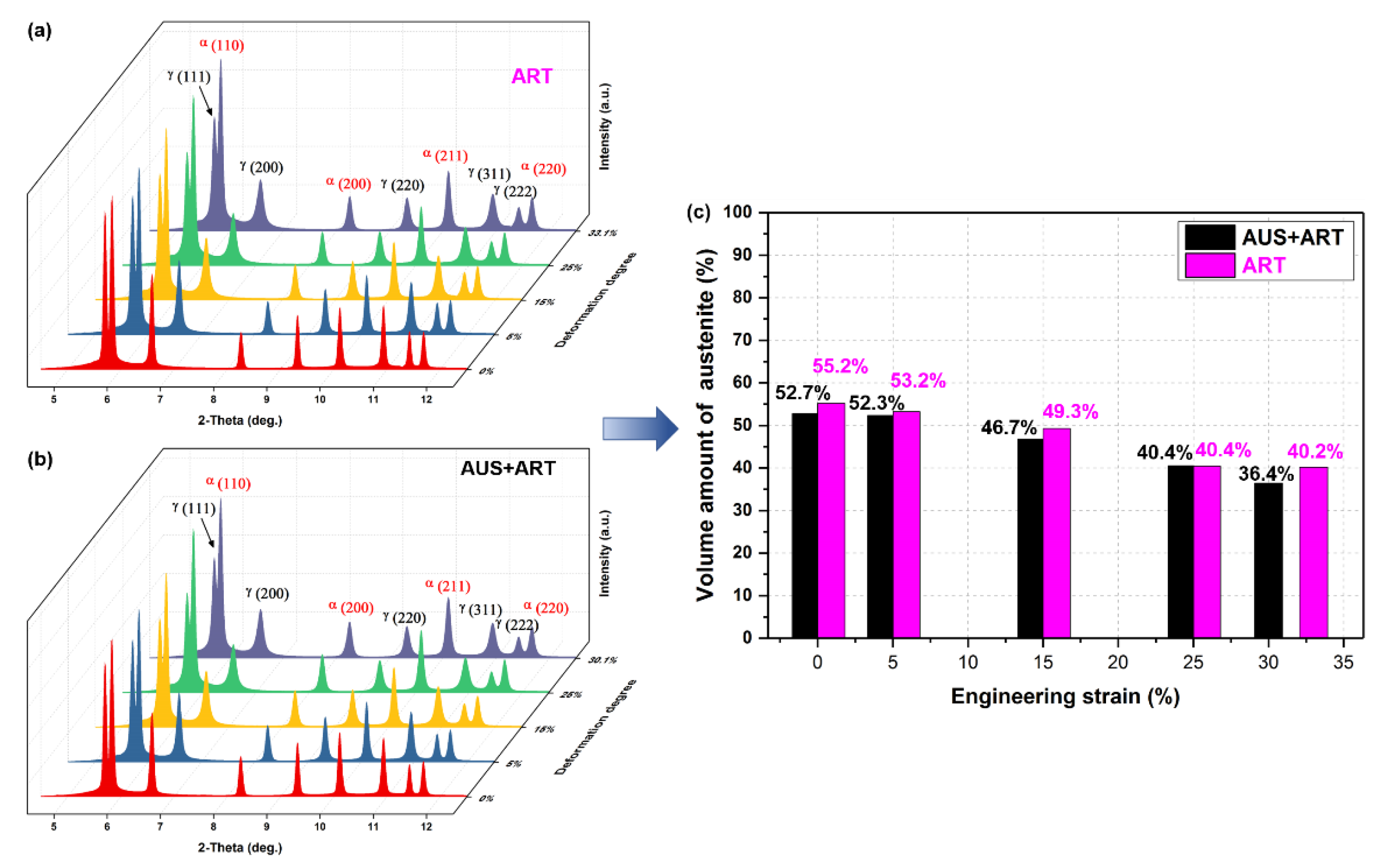
3.1.2. Quantitative Analysis of Microstructure by Synchrotron X-ray Diffraction (SYXRD)

SYXRD enables quantitative analysis of mechanical stability and volume fraction of austenite. Interrupted tensile tests were employed with a termination strain of 5%, 15% and 25%. The SYXRD measurements were performed on the uniform elongation zone next to necking areas. Figure 4a,b show the SYXRD profile of specimens with increasing deformation degree. The volume fractions of austenite within the deformed and undeformed microstructure were determined from fitting results by MAUD software. In the initial microstructure, ART specimen and AUS + ART specimen revealed a comparable amount of austenite, with a slight difference of ~2%. During deformation, austenite transformed into martensite due to relatively low mechanical stability, resulting in strain-hardening behavior. At the end of the deformation (engineering strain from 25% to 30.1%), the transformation amount of austenite in AUS + ART was still high, which dropped from 40.4% to 36.4%. Conversely, an extremely small amount of austenite transformation from 40.4% to 40.2% was observed in ART specimen with an engineering strain from 25% to 33.1%, which suggests that the TRIP effect rarely contributed to deformation at this stage.

3.2. Mechanical Properties

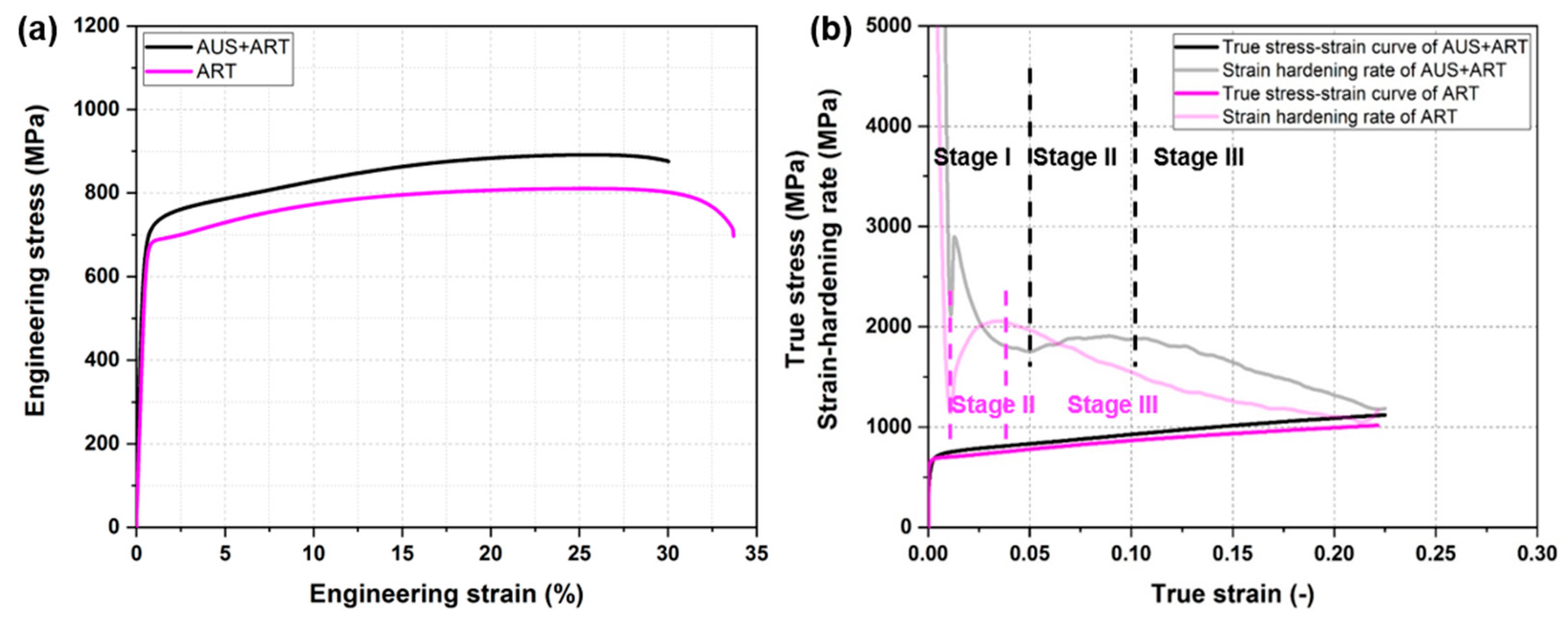
3.2.1. Tensile Properties

Figure 5a shows the engineering stress-engineering strain diagrams of the medium-Mn steel Fe-12Mn-3Al-0.05C after heat treatment ART and AUS + ART. The quasi-static tensile tests were conducted at room temperature at a consistent strain rate of 10−3 s−1. The mechanical properties of ART and AUS + ART specimens were comparable. The ART specimen revealed a slightly higher total elongation of 33.1% and a relatively lower ultimate tensile strength (UTS) of 811 MPa. The yield strength was 680 MPa. AUS + ART specimen exhibited an improved yield strength of 701 MPa and an enhanced UTS of 891 MPa with a total elongation of just over 30%.
Figure 5b illustrates true stress-true strain curves and the respective strain-hardening curves of the medium-Mn steel Fe-12Mn-3Al-0.05C after heat treatment ART and AUS + ART. Three stages can be distinguished clearly in the curves according to their distinct characteristics. In stage I, the strain-hardening rate dropped from an extremely high value. The ART specimen terminated stage I earlier than AUS + ART specimen. During stage II, the strain-hardening rates increased during plastic deformation before the strain-hardening rates decreased in stage III until the UTS point. The end values of stage III were almost the same in two specimens, around 1000 MPa. In general, the elevated strain-hardening rate contributed to the enhanced strength in AUS + ART specimen.

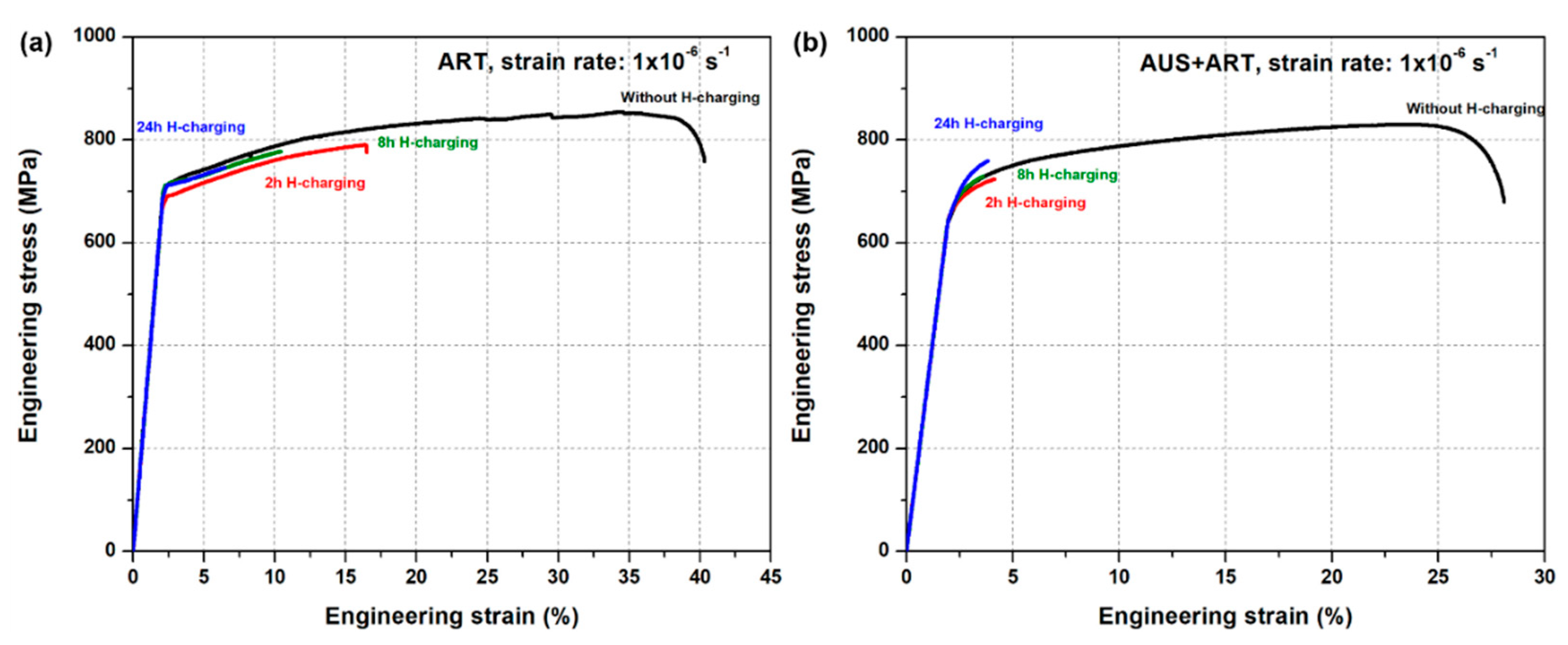
3.2.2. Mechanical Degradation Due to Hydrogen Ingression

To evaluate the hydrogen embrittlement susceptibility, ART specimen and AUS + ART specimen underwent an ex situ slow strain rate tensile (SSRT) test until fracture at different states, namely, uncharged, 2 h H-charged, 8 h H-charged, 24 h H-charged. The strain rate was set at 1 × 10⁻⁶ s−1 to ensure that the fracture behavior was predominated by the delayed hydrogen-induced cracks [35]. The elastic part was calibrated and modified with a defined slope, in order to shorten the elastic region and make the results comparable. Figure 6 exhibits the mechanical properties before and after hydrogen ingression in two groups of specimens. The HE susceptibility can be evaluated by the degradation of mechanical properties. On the one hand, the hydrogen content manifested little influence on strength in both groups of specimens. Yield strengths remained unchanged while the UTS points were not reached before hydrogen-induced brittle fracture. On the other hand, the distinct responses of ductility to hydrogen ingression were observed. The ART specimen experienced a clear ductile-to-brittle transition with increasing hydrogen uptake. With an increase in hydrogen charging time, the strain losses became greater. Differently, the presence of even a small amount of hydrogen in the AUS + ART specimen led to catastrophic failure. Upon charging with hydrogen, the specimen fractured at a very early stage with a limited total elongation of around 4%, regardless of the hydrogen content.

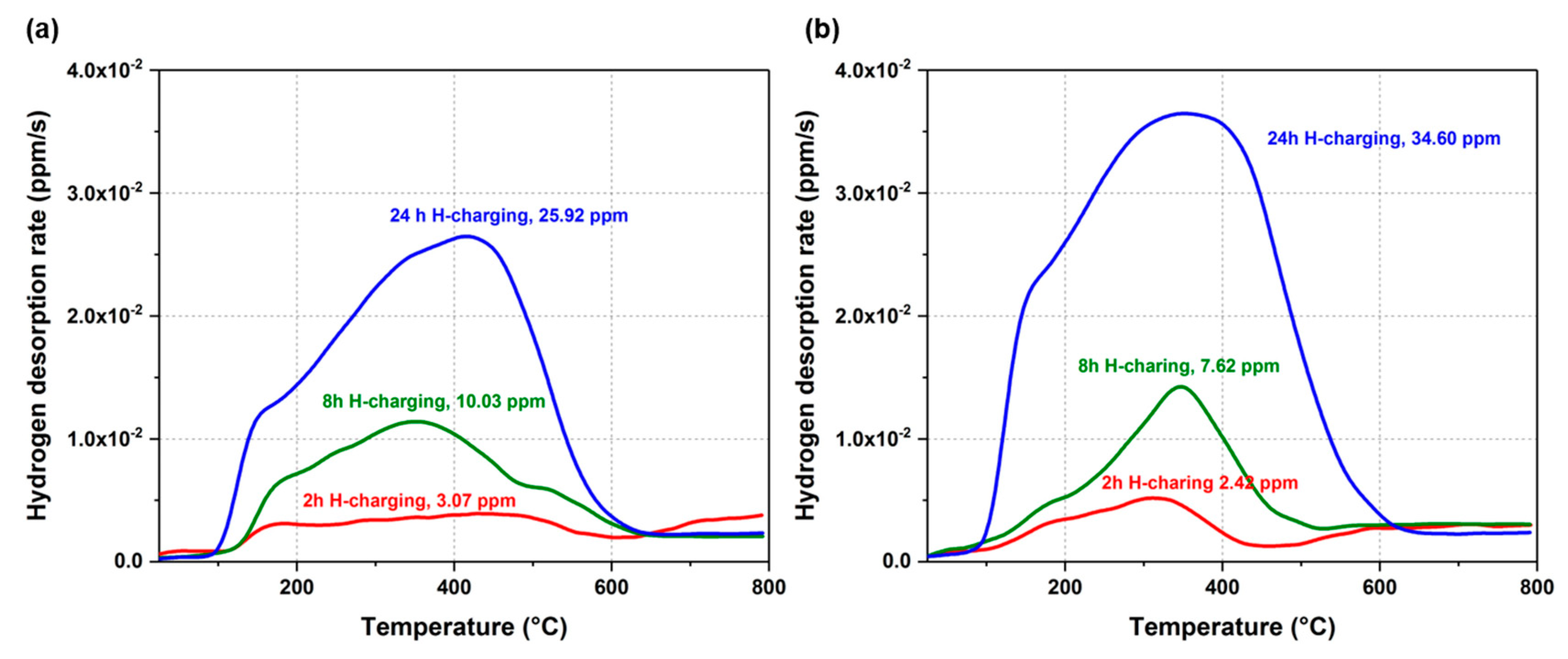
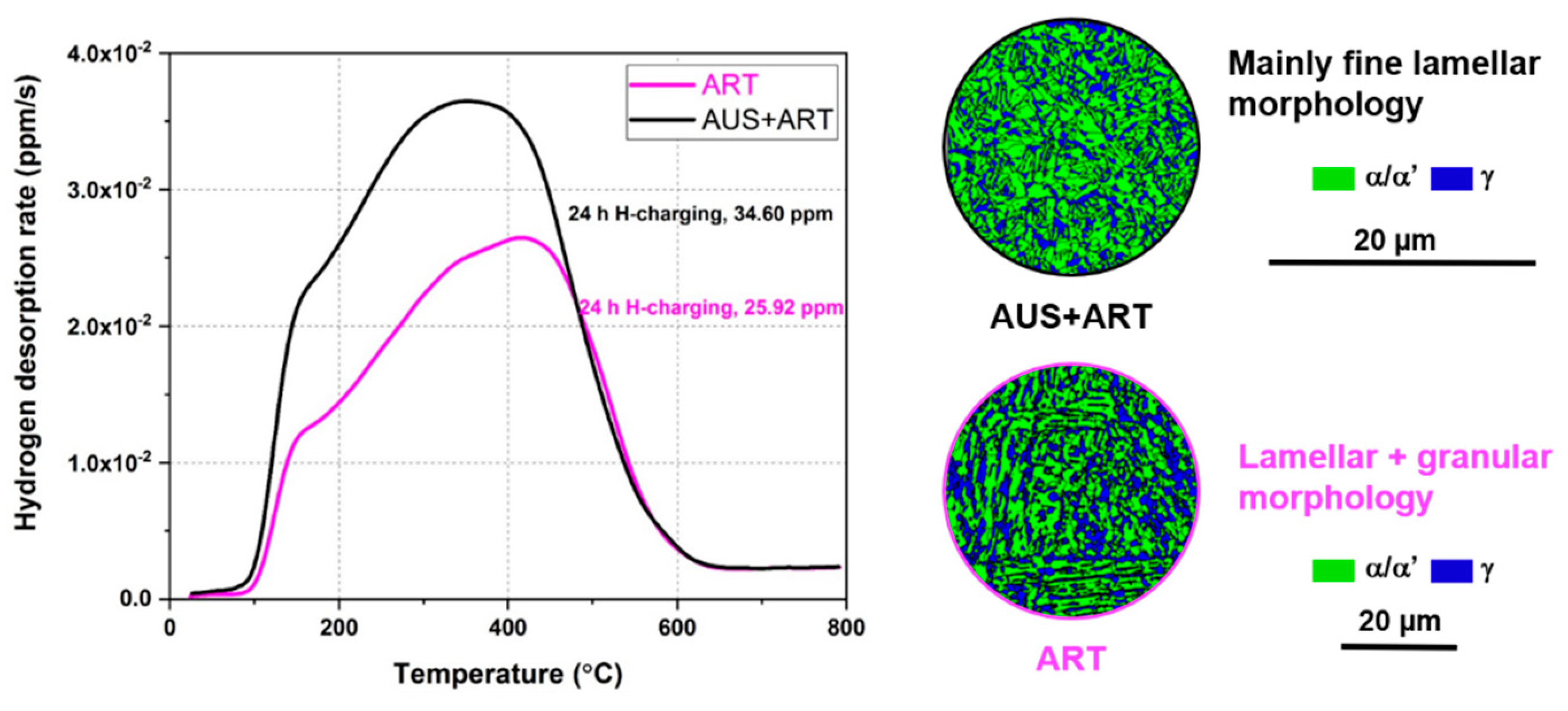
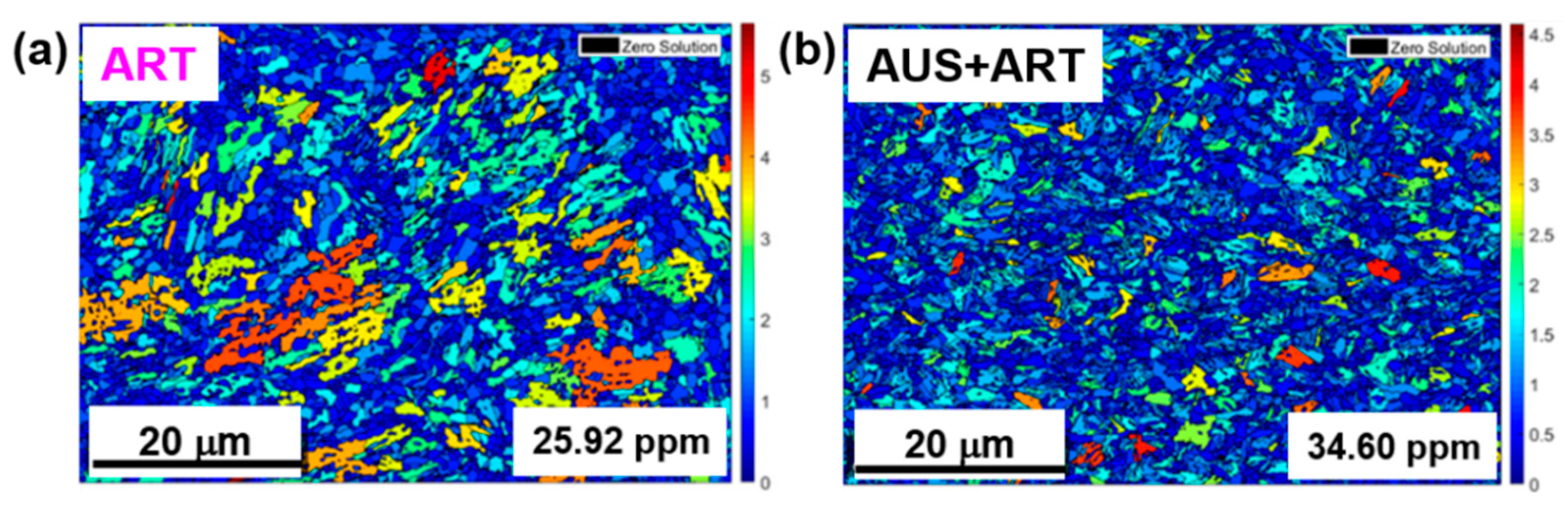
3.3. Hydrogen Uptake
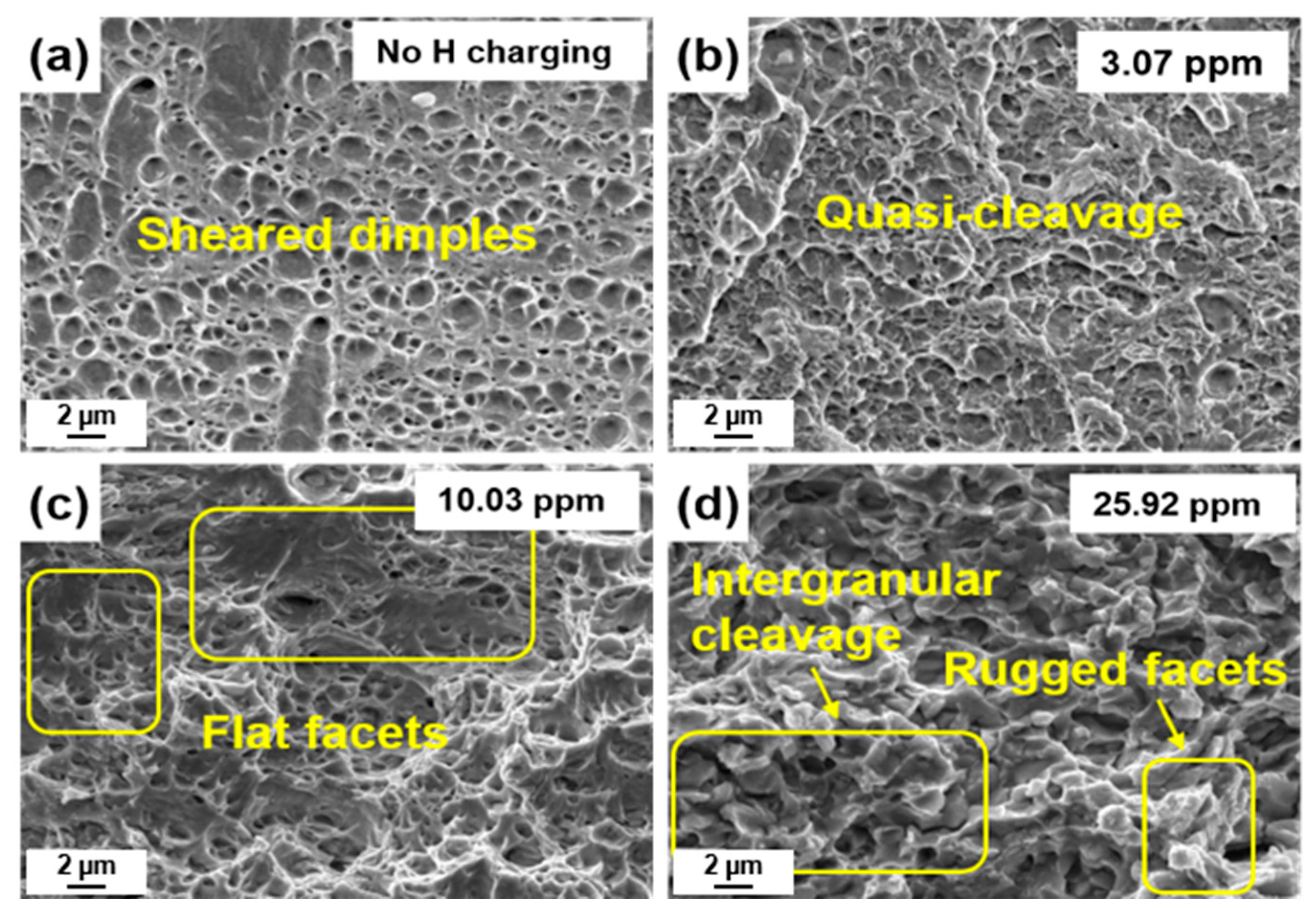
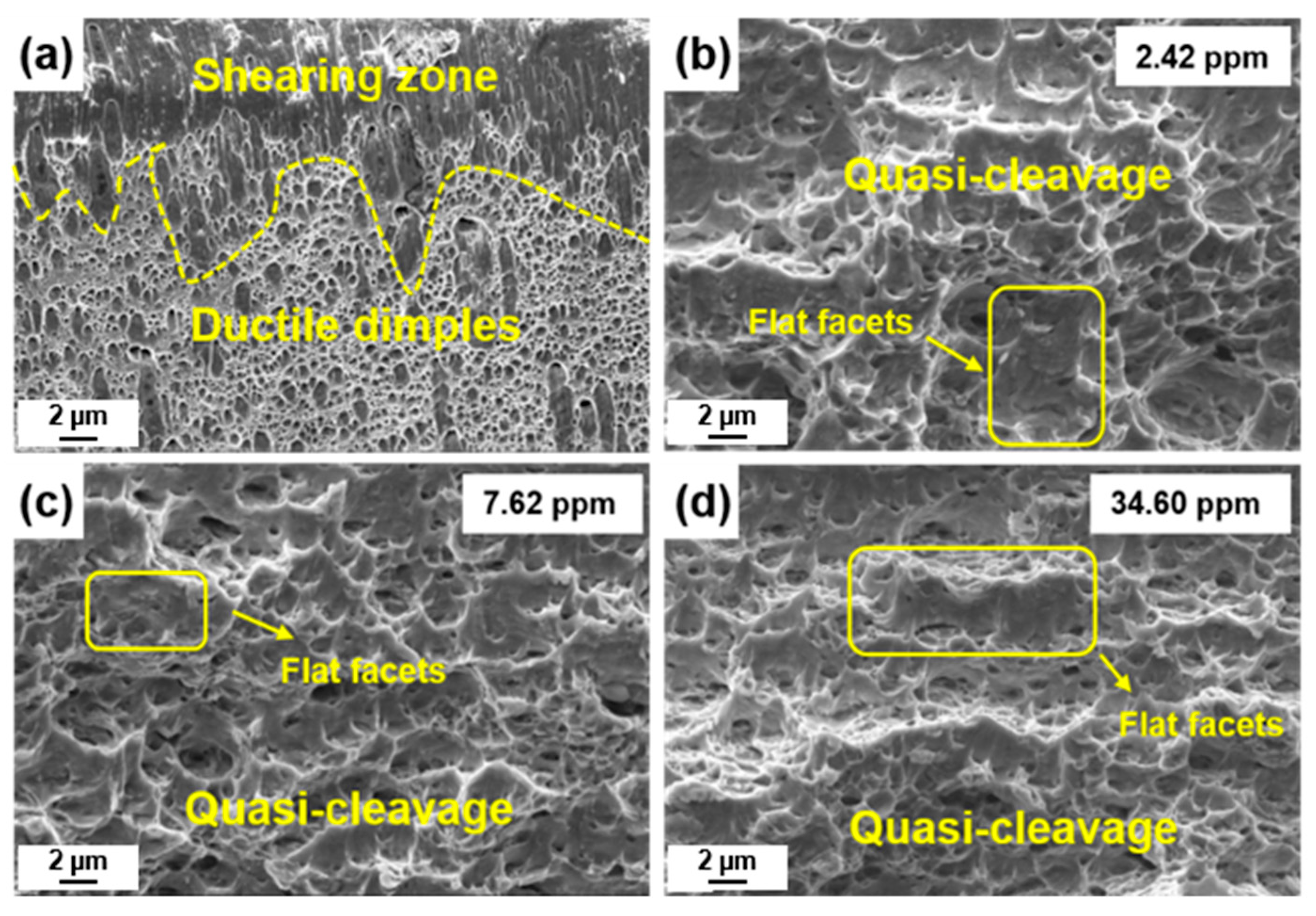
For a comprehensive understanding of hydrogen uptake in H-charged medium-Mn steel Fe-12Mn-3Al-0.05C, the thermal desorption rates are plotted in Figure 7. For uncharged specimens, the hydrogen desorption rates remained low from room temperature to 500 °C, and started to increase subsequently until 800 °C, which mostly referred to the hydrogen constrained at irreversible traps with high desorption energy. These hydrogen atoms were introduced during the steel making process. After 2 h of hydrogen charging, both ART specimen and AUS + ART specimen showed an immediate increase in diffusive hydrogen content, containing 3.07 ppm and 2.42 ppm hydrogen, respectively. The contents of diffusive hydrogen increased dramatically with the extended charging time. The hydrogen desorption rate curve always experienced a decreased slope around 170 °C and a top peak around 350 °C to 400 °C. These two features corresponded to a desorption peak of the martensite phase and austenite phase, respectively [18,36]. The hydrogen concentration saw a significant difference when the H-charging time was extended to 24 h. The hydrogen concentration in AUS + ART specimen was elevated although they consisted of a similar constitution.

3.4. Fractography

In order to understand the influence of hydrogen ingression on the fracture mode, the photographs of fracture surfaces were taken by SEM. Figure 8 reveals the fracture surface at the edge region (close to the lateral surface) of ART specimen at different hydrogen charging states. Compared with the middle regions of the fracture surface, edge regions revealed more apparent characteristics of hydrogen-induced failure and crack initiation due to the limited penetration depth. The difference was remarkable by comparing the fracture features, which can account for the transition from ductile to brittle. The specimen without hydrogen charging (Figure 8a) showed fully ductile dimples at the edge regions. Due to the non-uniaxial stress state, dimples next to the surface were sheared. The presence of 3.07 ppm hydrogen content (Figure 8b) led to mainly quasi-cleavage fracture, which refers to brittle failure on non-cleavage planes. 8-h hydrogen charging induced moderate hydrogen content of 10.03 ppm, producing pronounced quasi-cleavage and a large area of flat facets on the fracture surfaces (Figure 8c). After hydrogen charging for 24 h (Figure 8d), 25.92 ppm hydrogen content resulted in intergranular cleavage regions and rugged facets. The ductile to brittle transition features were clear by comparing the fracture features at the edge regions, which could account for the increase of strain loss with increasing hydrogen charging time.
Hydrogen ingression in AUS + ART specimens always led to more than 85% strain loss, regardless of the hydrogen content. Figure 9 displayed the fracture surfaces at the edge region of AUS + ART specimen. The edge region of the uncharged specimen revealed a fully ductile fracture (Figure 9a). The elongated dimples were also caused by a non-uniaxial stress state near the surface. Recalling from the mechanical degradation that was evaluated by SSRT, the fracture surface at the edge region was assumed to be consistent regardless of the hydrogen content because they all showed extremely early fracture (~4% total elongation). From Figure 9b–d, representing hydrogen charging for 2 h, 8 h, 24 h, respectively, the fracture surfaces at the edge region were composed of quasi-cleavage and a large area of flat facets. The fracture surfaces revealed typical features after hydrogen charging. A detailed interpretation of operative fracture mechanisms is discussed in the following section.

4. Discussion

4.1. Microstructure–Mechanical Properties Correlation

The ART specimen revealed an austenite-martensite/ferrite duplex microstructure. Austenite films were located between large martensite laths, while fine-grained globular austenite and martensite grains were also observed (Figure 2). The AUS+ART specimen revealed mainly ultrafine-grained martensite colonies with the decoration of thin austenite films, globular austenite grains and globular martensite grains (Figure 3). The microstructure features and mechanical properties are summarized in Table 2. The effective grain size was used to describe the size of the martensite package, inherited from prior austenite grains. The enhanced strength of AUS + ART specimen was mainly attributed to the strong strain-hardening effect (Figure 5b) and the Hall–Petch effect induced by the large density of interfaces. During deformation-induced martensitic transformation, dynamic Hall–Petch effect takes place when introducing new interfaces, such as phase boundaries and lath boundaries, leading to the elevated strain-hardening rates [37]. These interfaces, in turn, act as obstacles to dislocation motion, increasing the dislocation generation rate in order for materials to accommodate plastic deformation. Therefore, the superior ductility ascribes to the delay of necking with the aid of the TRIP effect and a significant accommodation of plastic deformation by generating mobile dislocations [37].

4.2. Influences of Microstrucal Morphology on Hydrogen Embrittlement in Fe-12Mn-3Al-0.05C Steels

ART specimen and AUS + ART specimen showed different responses to hydrogen embrittlement, resulting in different failure behaviors. The prediction of the hydrogen embrittlement mechanisms focused on two main aspects, hydrogen absorption and fracture mode.
Considering the similar constitution of initial microstructure and the same hydrogen charging conditions, the divergence in hydrogen absorption might be attributed to the distinct microstructural morphologies. The very early fracture in all AUS + ART specimens with different hydrogen contents (Figure 6b) manifests that the hydrogen amount is not the critical controlling factor. Correlating the hydrogen desorption curve with the microstructure (as shown in Figure 10), the increased hydrogen content and catastrophic failure may be correlated with the large interface density in AUS + ART.
The microstructure of AUS + ART consisted mainly of fine martensite colonies with a package size of 3 μm, which provided a large number of interfaces. These interfaces included the martensite lath boundaries, prior austenite grain boundaries and phase boundaries. During hydrogen charging, hydrogen atoms tend to trap at these interfaces. A large number of interfaces provides more trapping sites for hydrogen atoms. Meanwhile, the interface may act as the fast diffusion path for hydrogen transportation. The increased hydrogen concentration in AUS + ART specimen might be attributed to the trapping and fast diffusion behaviors of hydrogen atoms.
The distinct fracture characteristics in ART and AUS + ART specimens result from the contributions of different hydrogen embrittlement mechanisms. In ART specimen, film-like austenite grains with a large aspect ratio are still able to transform even after strong hydrogen ingression (warm-color region in Figure 11a), which is probably related to the hydrogen-enhanced localized plasticity (HELP) mechanism. The austenite film revealed a high GOS value within grains. Therefore, rugged facets in Figure 8d can be observed due to the repeated onset of a localized TRIP effect and the HEDE mechanism [18]. The TRIP effect in Mn-containing advanced high strength steels (AHSS) is considered to be vulnerable to HE, due to the localized deformation and cracking initiation, which is consistent with the published results [16,17,19]. In the highly hydrogen-affected specimen (hydrogen-charging for 24 h), the HEDE mechanism possibly became the predominant effect, reducing the cohesive bonding strength of the lattice [18,24]. Thus, the clear intergranular cleavage as directly observed in Figure 8d. Additionally, the crack propagation was reported to be impeded in the granular region, because cracks have to change the direction of propagation frequently when entering the phase in the vicinity [18].
The hydrogen trapped at interfaces was widely considered to decrease the bonding strength according to HEDE mechanism. The strong diffusion and accumulation of hydrogen atoms at interfaces in the AUS + ART specimen were assumed to be responsible for the premature fracture. The large number of interfacial defects in the UFG microstructure directly gives more chances for incubation of cracking. The reduced bonding strength may also facilitate the nucleation and emission of dislocation according to the absorption-induced dislocation emission (AIDE) mechanism [21,38], leaving small and shallow dimples at the fracture surfaces. Localized micro-strain (shown in the red region in Figure 11b) drives dislocations to interact with voids and initiate the cracks. The large area of interfaces provides a significant chance to form cracks in AUS + ART specimen, resulting in poor hydrogen embrittlement resistance.

4.3. Thermodynamic Assessment

To complement the experimental observations, we considered qualitatively conceivable relevant failure scenarios. While kinetic features, specifically interface diffusion, can be expected to play an important role, our focus here was on thermodynamic aspects. Concretely, we assumed that the failure originated from the precipitation of hydrogen-rich phases directly at a grain boundary (GB). We considered the dependence of the formation of such hydrogen-rich phases on the microstructural influences that resulted from heat treatment (ART or AUS + ART). The decisive quantity was the GB distribution in the different microstructures, which vary depending on the type of heat treatment. To relate the difference in GB distribution to divergencies in the formation of hydrogen-rich phases, we connected the local elastic modulus of the GBs to the modification of the local chemical equilibrium at the GBs. We referred to our previous work, where we considered the modification of the hydrogen solubility in iron due to elastic effects [39], which can result in localized nano-hydride formation [40]. As shown in Equation (68) in [39], the shifted solubility limit of hydrogen can be described as a result of a modified elastic relaxation of the coherency stresses close to and at interfaces, which are caused by the precipitation of the hydrogen-rich phase. While precipitates close to a free surface experience less elastic response to the coherency stresses, a rigid surface represents the opposite case, exhibiting a reduced elastic relaxation of the coherency stresses close to or at the interface. The resulting reduction of the hydrogen solubility limit can be up to two orders of magnitude in comparison to bulk locations at room temperature in the case of free surfaces.
To connect these fundamental findings with our experimental observations, we refer to the investigation of the local elastic properties of GBs in iron published in [41]. Though limited to symmetrical GBs, we used the presented data on the local Young’s modulus of various grain boundaries as representatives of high angle and low angle grain boundaries. We noted that the range of local Young’s modulus in the GB plane was 130–176 MPa in the GB, the minimum associated withe the lowest tilt angle (approx. 39 degrees), the maximum related to the highest tilt angle (approx. 109 degrees). Consequently, we can expect that a higher fraction of low angle GBs, associated with lower local Young’s modulus, results in a substantially reduced hydrogen solubility, therefore supporting hydride formation and failure. After making this connection between GB character and local Young’s modulus, we needed to relate the GB distribution to the hydrogen-induced failure of the specimens. We referred to [42], where the distribution of low and high angle grain boundaries was reported for TWIP steels, depending on the average grain size. Only for the UFG case, low angle grain boundaries, did we expect from our considerations to support precipitation of hydrogen-rich phases and not be suppressed. Consequently, the hydrogen failure in the UFG sample, specifically its independence on the hydrogen ingression, can be explained also from a thermodynamic perspective. The higher fraction of low angle grain boundaries in AUS + ART specimen resulted in a higher fraction of sites prone to the formation of hydrogen-rich phases, as the relaxation of the associated coherency stresses increased. The elevated hydrogen concentration in AUS + ART specimen was attributed to the fast hydrogen ingression and precipitation of brittle hydrogen-rich phases from a thermodynamic perspective, leading to premature failure.

5. Conclusions

In the current work, the mechanical properties and hydrogen embrittlement susceptibility were investigated in a cold-rolled medium-Mn Fe-12Mn-3Al-0.05C steel. Important conclusions from the present study were summarized as follows:
(1)
A combination of austenitization annealing (AUS) and austenite-reversed transformation (ART) produced comparable mechanical properties (UTS = 891 MPa, Y.S. = 701 MPa, total elongation = 30.1%) as that in a routine where the ART annealing was applied immediately after cold rolling.
(2)
The ultrafine-grained martensite colonies provided a large number of interfaces (prior austenite boundaries and lath boundaries) for hydrogen trapping, which increased the hydrogen ingression.
(3)
ART specimen revealed a clear ductile-brittle transition with increasing hydrogen concentration. Hydrogen embrittlement is considered to be predominated by concurrent contribution of HEDE and HELP mechanisms.
(4)
AUS + ART specimen exhibited extremely high hydrogen susceptibility of the ductility regardless of hydrogen concentration. The brittle failure in H-charged samples was attributed to the HEDE mechanism in the UFG microstructure with a large number of interfaces, and to possible contribution by the AIDE mechanism.
(5)
Consideration of thermodynamic factors suggest that the failure discrepancy in the UFG and non-UFG specimens was likely to be related to the facilitation of hydrogen-rich phase precipitation by interfacial defects.

Author Contributions

W.S and X.S. designed the experiments. Y.M. and X.S. performed and analyzed most of the experiments (e.g., SEM, SYXRD, SSRT, TDA). S.S. performed the EBSD measurement and analyzed the data. H.C. and S.R. contributed to the theoretical interpretation in the perspective of thermodynamics. W.B. and W.S. supervised this work and contributed to intensive discussions. All authors contributed to the interpretation of the results and the writing of the final version of the manuscript.

Funding

This research work and APC were funded by the Deutsche Forschungsgemeinschaft (DFG) within the Collaborative Research Center (SFB) 761 “Steel—ab initio: quantum mechanics guided design of new Fe-based materials”.

Acknowledgments

The synchrotron X-ray diffraction measurements were carried out at beamline P02.1 of PETRA III at DESY, a member of the Helmholtz Association (HGF), which is gratefully acknowledged. A sincere thanks also goes to colleagues at Welding and Joining Institute (ISF), RWTH Aachen university for the help with performing the hydrogen desorption experiments.

Conflicts of Interest

The authors declare no conflict of interest.

References

  1. Miller, R.L. Ultrafine-grained microstructures and mechanical properties of alloy steels. Metall. Trans. 1972, 3, 905–912. [Google Scholar] [CrossRef]
  2. Han, J.; Lee, S.J.; Lee, C.Y.; Lee, S.; Jo, S.Y.; Lee, Y.K. The size effect of initial martensite constituents on the microstructure and tensile properties of intercritically annealed Fe–9Mn–0.05C steel. Mater. Sci. Eng. A 2015, 633, 9–16. [Google Scholar] [CrossRef]
  3. Lee, S.W.; De Cooman, B.C. Tensile behavior of intercritically annealed 10 pct Mn multi-phase steel. Metall. Mater. Trans. A. 2013, 45, 709–716. [Google Scholar] [CrossRef]
  4. Lee, S.W.; Woo, W.C.; De Cooman, B.C. Analysis of the tensile behavior of 12 pct Mn multi-phase (α + γ) TWIP + TRIP steel by neutron diffraction. Metall. Mater. Trans. A. 2016, 47A, 2125–2140. [Google Scholar] [CrossRef]
  5. Lee, S.J.; Lee, S.W.; De Cooman, B.C. Mn partitioning during the intercritical annealing of ultrafine-grained 6% Mn transformation-induced plasticity steel. Scripta Mater. 2011, 64, 649–652. [Google Scholar] [CrossRef]
  6. Luo, H.; Shi, J.; Wang, C.; Cao, W.; Sun, X.; Dong, H. Experimental and numerical analysis on formation of stable austenite during the intercritical annealing of 5Mn steel. Acta Mater. 2011, 59, 4002–4014. [Google Scholar] [CrossRef]
  7. Lee, Y.K.; Han, J. Current opinion in medium manganese steel. Mater. Sci. Tech. 2015, 31, 843–856. [Google Scholar] [CrossRef]
  8. Ma, Y. Medium-manganese steels processed by austenite-reverted-transformation annealing for automotive application. Mater. Sci. Tech. 2017, 33, 1713–1727. [Google Scholar] [CrossRef]
  9. Ma, Y.; Song, W.; Zhou, S.; Schwedt, A.; Bleck, W. Influence of intercritical annealing temperature on microstructure and mechanical properties of a cold-rolled medium-Mn steel. Metals 2018, 8, 357. [Google Scholar] [CrossRef]
  10. Haupt, M.; Dutta, A.; Ponge, D.; Sandlöbes, S.; Nellessen, M.; Hirt, G. Influence of intercritical annealing on microstructure and mechanical properties of a medium manganese steel. Procedia Engineer. 2017, 207, 1803–1808. [Google Scholar] [CrossRef]
  11. Edmonds, D.V.; He, K.; Rizzo, F.C.; De Cooman, B.C.; Matlock, D.K.; Speer, J.G. Quenching and partitioning martensite—A novel steel heat treatment. Mater. Sci. Eng. A. 2006, 438, 25–34. [Google Scholar] [CrossRef]
  12. Arlazarov, A.; Gouné, M.; Bouaziz, O.; Hazotte, A.; Kegel, F. Effect of intercritical annealing time on microstructure and mechanical behavior of advanced medium Mn steels. Mater. Sci. Forum. 2012, 706, 2693–2698. [Google Scholar] [CrossRef]
  13. Furukawa, T.; Huang, H.; Matsumura, O. Effects of carbon content on mechanical properties of 5%Mn steels exhibiting transformation induced plasticity. Mater. Sci. Tech. 1994, 10, 964–970. [Google Scholar] [CrossRef]
  14. De Moor, E.; Matlock, D.K.; Speer, J.G.; Merwin, M.J. Austenite stabilization through manganese enrichment. Scripta. Mater. 2011, 64, 185–188. [Google Scholar] [CrossRef]
  15. Furukawa, T. Dependence of strength–ductility characteristics on thermal history in low-carbon, 5 wt-%Mn steels. Mater. Sci. Tech. 1989, 5, 465–470. [Google Scholar] [CrossRef]
  16. Ryu, J.H.; Chun, Y.S.; Lee, C.S.; Bhadeshia, H.K.D.H.; Suh, D.W. Effect of deformation on hydrogen trapping and effusion in TRIP-assisted steel. Acta Mater. 2012, 60, 4085–4092. [Google Scholar] [CrossRef]
  17. Wang, M.; Tasan, C.C.; Koyama, M.; Ponge, D.; Raabe, D. Enhancing hydrogen embrittlement resistance of lath martensite by Introducing nano-films of interlath austenite. Metall. Mater. Trans. A. 2015, 46A, 3797–3802. [Google Scholar] [CrossRef]
  18. Han, J.; Nam, J.H.; Lee, Y.K. The mechanism of hydrogen embrittlement in intercritically annealed medium Mn TRIP steel. Acta Mater. 2016, 113, 1–10. [Google Scholar] [CrossRef]
  19. Zhang, Y.; Hui, W.; Zhao, X.; Wang, C.; Cao, W.; Dong, H. Effect of reverted austenite fraction on hydrogen embrittlement of TRIP-aided medium Mn steel (0.1C-0.5Mn). Eng. Fail. Anal. 2019, 97, 605–616. [Google Scholar] [CrossRef]
  20. Jeong, I.; Ryu, K.M.; Lee, D.G.; Jung, Y.; Lee, K.; Lee, J.S.; Suh, D.W. Austenite morphology and resistance to hydrogen embrittlement in medium Mn transformation-induced plasticity steel. Scripta Mater. 2019, 169, 52–56. [Google Scholar] [CrossRef]
  21. Lynch, S. Hydrogen embrittlement phenomena and mechanisms. Corros. Rev. 2012, 30, 105–123. [Google Scholar] [CrossRef]
  22. Robertson, I.M.; Sofronis, P.; Nagao, A.; Martin, M.L.; Wang, S.; Gross, D.W.; Nygren, K.E. Hydrogen embrittlement understood. Metall. Mater. Trans. A 2015, 46A, 2323–2341. [Google Scholar] [CrossRef]
  23. Troiano, A.R. The role of hydrogen and other interstitials in the mechanical behavior of metals. Metallogr. Microstruct. Anal. 2016, 5, 557–569. [Google Scholar] [CrossRef]
  24. Oriani, R.A. A mechanistic theory of hydrogen embrittlement of steels. Berich. Bunsen. Gesell. 1972, 76, 848–857. [Google Scholar]
  25. Beachem, C.D. A new model for hydrogen-assisted cracking (hydrogen “embrittlement”). Metall. Mater. Trans. B. 1972, 3, 441–455. [Google Scholar] [CrossRef]
  26. Robertson, I.M. The effect of hydrogen on dislocation dynamics. Eng. Fract. Mech. 2001, 68, 671–692. [Google Scholar] [CrossRef]
  27. Du, X.; Cao, W.; Wang, C.; Li, S.; Zhao, J.; Sun, Y. Effect of microstructures and inclusions on hydrogen-induced cracking and blistering of A537 steel. Mater. Sci. Eng. A. 2015, 642, 181–186. [Google Scholar] [CrossRef]
  28. Mohtadi-Bonad, M.A.; Ghesmati-kucheki, H. Important factors on the failure of pipeline steels with focus on hydrogen induced cracks and improvement of their resistance: Review paper. Met. Mater. Int. 2019, 1, 1–26. [Google Scholar]
  29. Mohtadi-Bonad, M.A.; Eskandari, M.; Szpunar, J.A. Effect of arisen dislocation density and texture components during cold rolling and annealing treatments on hydrogen induced cracking susceptibility in pipeline steel. J. Mater. Res. 2016, 31, 3390–3400. [Google Scholar] [CrossRef]
  30. Bachmann, F.; Hielscher, R.; Schaeben, H. Texture Analysis with MTEX—Free and Open Source Software Toolbox. SSP 2010, 160, 63–68. [Google Scholar] [CrossRef]
  31. Hielscher, R.; Schaeben, H. A novel pole figure inversion method: Specification of the MTEX algorithm. J. Appl. Crystallogr. 2008, 41, 1024–1037. [Google Scholar] [CrossRef]
  32. Hammersley, A.P.; Svensson, S.O.; Hanfland, M.; Fitch, A.N.; Hausermann, D. Two-dimensional detector software: From real detector to idealized image or two-theta scan. High Pressure Res. 1996, 14, 235–248. [Google Scholar] [CrossRef]
  33. Young, R.A. The Rietveld Method, 4th ed.; Oxford University Press Inc.: New York, NY, USA, 2002. [Google Scholar]
  34. Field, D.P.; Bradford, L.T.; Nowell, M.M.; Lillo, T.M. The role of annealing twins during recrystallization of Cu. Acta Mater. 2007, 55, 4233–4241. [Google Scholar] [CrossRef]
  35. Henthorne, M. The slow strain rate stress corrosion cracking test—A 50 year retrospective. Corrosion 2016, 72, 1488–1518. [Google Scholar] [CrossRef]
  36. Park, Y.; Maroef, I.; Landau, A.; Olson, D. Retained austenite as a hydrogen trap in steel welds. Weld. J. 2002, 71, 27–35. [Google Scholar]
  37. Sevsek, S.; Haase, C.; Bleck, W. Strain-rate-dependent deformation behavior and mechanical properties of a multi-phase medium-manganese steel. Metals 2019, 9, 344. [Google Scholar] [CrossRef]
  38. Lynch, S.P. Metallographic contributions to understanding mechanisms of environmentally assisted cracking. Metallography 1989, 23, 147–171. [Google Scholar] [CrossRef]
  39. Spatschek, R.; Gobbi, G.; Hütter, C.; Chakrabarty, A.; Aydin, U.; Brinckmann, S.; Neugebauer, J. Scale bridging description of coherent phase equilibria in the presence of surfaces and interfaces. Phys. Rev. B 2016, 94, 134106. [Google Scholar] [CrossRef] [Green Version]
  40. Pezold, J.; Lymperakis, L. Neugebauer, Hydrogen-enhanced local plasticity at dilute bulk H concentrations: The role of H-H interactions and the formation of local hydrides. Acta Mater. 2011, 59, 2969–2980. [Google Scholar] [CrossRef]
  41. Bhattacharya, S.; Tanaka, S.; Shiihara, Y.; Kohyama, M. Ab initio perspective of the (110) symmetrical tilt grain boundaries in bcc Fe: application of local energy and local stress. J. Mater. Sci. 2014, 49, 3980–3995. [Google Scholar] [CrossRef]
  42. Bai, Y.; Momotani, Y.; Chen, M.C.; Shibata, A.; Tsuji, N. Effect of grain refinement on hydrogen embrittlement behaviors of high-Mn TWIP steel. Mater. Sci. Eng. A 2016, 651, 935–944. [Google Scholar] [CrossRef] [Green Version]
Figure 1. Schematic illustration of thermal cycles on cold-rolled Fe-12Mn-3Al-0.05C steel after cold rolling (WQ denotes water cooling; CR denotes cold rolling).
Metals 09 00929 g001
Figure 2. Electron backscatter diffraction measurement of initial microstructure in austenite-reverted-transformation annealed specimen, including (a) forescatter diode image, (b) phase distribution map, (c) inverse pole figure and (d) grain orientation spread image. The dashed box in (a) denotes the analyzed region for (bd); red arrows in (b) indicates globular grains; white arrows marks the band-shaped lamellar grains.
Metals 09 00929 g002
Figure 3. Electron backscatter diffraction measurement of initial microstructure in AUS + ART annealed specimen, including (a) forescatter diode image, (b) phase distribution map, (c) inverse pole figure and (d) grain orientation spread image. The dashed box in (a) denotes the analyzed region for (bd); red arrows in (b) indicates globular grains; white arrows marks the band-shaped lamellar grains.
Metals 09 00929 g003
Figure 4. Synchrotron X-ray diffraction profile of (a) austenite-reverted-transformation specimen; (b) AUS + ART specimen with increasing deformation degree. (c) volume fraction of austenite in samples in the as-annealed condition as well as taken from interrupted tensile tests at different strains.
Metals 09 00929 g004
Figure 5. (a) Engineering stress-engineering strain curves; (b) true stress-true strain curves and strain-hardening curves of the medium-Mn steel Fe-12Mn-3Al-0.05C after heat treatment austenite-reverted-transformation (ART) and AUS + ART.
Metals 09 00929 g005
Figure 6. Evaluation of mechanical degradation by ex-situ slow strain rate tensile test at a strain rate of 10−6 s−1 in (a) ART specimen; and (b) AUS + ART specimen.
Metals 09 00929 g006
Figure 7. Hydrogen desorption rate as a function of temperature in (a) austenite-reverted-transformation (ART) specimen; and (b) AUS + ART specimen.
Metals 09 00929 g007
Figure 8. Fracture surfaces at the edge region of austenite-reverted-transformation annealed specimens undergone slow strain rate tensile until fracture. (a) No H-charged state; (b) H-charged for 2 h with 3.07 ppm; (c) H-charged for 8 h with 10.03 ppm. (d) H-charged for 24 h with 25.92 ppm.
Metals 09 00929 g008
Figure 9. Fracture surfaces at the edge region of AUS + ART annealed specimens experienced slow strain rate tensile. (a) No H-charged state; (b) H-charged for 2 h with 2.42 ppm; (c) H-charged for 8 h with 7.62 ppm. (d) H-charged for 24 h with 34.60 ppm.
Metals 09 00929 g009
Figure 10. Hydrogen desorption rate as a function of temperature and the corresponding microstructural features.
Metals 09 00929 g010
Figure 11. Grain orientation spread figures of (a) austenite-reverted-transformation (ART) and (b) AUS + ART specimens undergone slow strain rate tensile test after 24-h hydrogen charging.
Metals 09 00929 g011
Table 1. Chemical composition of the investigated material as determined by wet chemical analysis.
ElementCSiMnPSAlFe
wt.%0.0640.211.70.0060.0032.9Bal.
Table 2. Summary of microstructural features and mechanical properties (A20: total elongation).
Heat TreatmentUTS/MPaA20/%Effective Grain Size/μmAustenite Fraction/%
α’ PackageGlobular Grains
ART81130.110–20~1.555.2
AUS + ART89133.11–5~153.1

