Re-Melting Nb–Si-Based Ultrahigh-Temperature Alloys in Ceramic Mold Shells


State Key Laboratory of Solidification Processing, Northwestern Polytechnical University, Xi’an 710072, China
*
Author to whom correspondence should be addressed.
Metals 2019, 9(7), 721; https://doi.org/10.3390/met9070721
Submission received: 1 June 2019
/
Revised: 18 June 2019
/
Accepted: 24 June 2019
/
Published: 26 June 2019
Abstract
:In furnaces with different heating elements, Nb–Si based ultrahigh-temperature alloy rods were re-melted in pure yttria mold shells and zirconia face-coat mold shells at 1850 °C for 30 min. The results evidenced that in the furnace with a tungsten heating element, the microstructure of the re-melted alloy became coarser, and the composition varied depending on the type of mold shell. Although the interface reaction layer between the re-melted alloy and the zirconia face-coat mold shell was much thicker, the deformability of the mold shell and the sand burning phenomenon of the alloy inside it were improved and ameliorated, respectively. However, after being re-melted in the furnace with a graphite heating element, the misrun phenomenon occurred in both specimens. Both re-melted alloys inside the mold shells were divided by a gap into an internal and an external part, with totally different microstructures and compositions. No reaction layer emerged at the interface between the re-melted alloy and the mold shells. Instead, infiltration zones arose in the mold shells adjacent to the interface.
1. Introduction
The new generation of turbine blade materials has encountered challenges from improving their temperature capability of the mounting requirement to the thrust weight ratio of aircraft engines [1]. It is difficult for conventional nickel-based superalloys to satisfy this demand in view of the fact that their operating temperature is extremely close to their melting point [2].
Against that backdrop, new high-temperature materials, such as Nb–Si based ultrahigh-temperature alloys have received sustained attention as a potential substitutive material for classical nickel-based superalloys. This is due not only to their higher melting temperatures, but also to their excellent high-temperature strength, room-temperature fracture toughness, and low densities [3,4,5,6]. According to recent studies, with respect to the hot workability of the alloys, it is rather laborious and impractical to produce their components and parts via forging methods because of the formation of cracks during hot deformation [7,8]. Investment casting has naturally become the ultimate forming process for this alloy. The technical advantage gained is due to two aspects. First, in contrast to wrought production methods, cracking does not occur when using this technology. Second, it is characterized by near-net-shape casting, and hence, can be applied to the manufacturing of various components with complex shapes [9,10].
However, when used to shape Nb–Si based ultrahigh-temperature alloys, this technology has its own issues to be settled. The first thing should be the selection of a refractory material for the mold shells. Because of the general addition of highly active alloying elements, such as Ti, Hf, etc., in the alloy, the interaction of the candidate shell material with the alloy’s melting must be taken into account. Zirconia and yttria are oxides with high chemical inertness and melting points of 2680 and 2410 °C, respectively. Correspondingly, they have been widely adopted as a face coating or adjacent face coating in mold shells for investment casting of active and refractory metals. Especially, yttria has been successfully applied in the preparation of directionally solidified Nb–Si based ultrahigh-temperature alloys with a single orientation structure and high mechanical properties. As an example, Guo and Guo [11] performed integrally directional solidification of Nb–Si based ultrahigh-temperature alloys, in which yttria was employed as crucible material. Ma et al. [12] technically studied the interface interactions between Nb–Si-based ultrahigh-temperature alloys and pure yttria mold shells and found only a 5 to 15 μm-thick reaction layer composed of HfO2 and Y2O3 formed at the metal–mold shell interface. This further confirms that yttria is relatively inert to this alloy and is a qualified material for the mold shell during investment casting of this alloy. However, yttria is inclined to be hydrated with water, which leads to a significant loss of the life period of the as-prepared slurries as a result of gelatinization [13]. This ineluctably increases the overall technical costs of investment casting. On the contrary, it is not an issue for slurries filled by zirconia. However, in view of the substitution reaction between ZrO2 and Hf, the application of zirconia on re-melting Nb–Si-based ultrahigh-temperature alloys is scarce. Nevertheless, the addition of Hf is becoming unnecessary, considering the impact of this element on the alloy, as reported recently [14]. It can be predicted that the content of Hf is likely to be reduced or replaced completely by other elements in the modified alloy. Hence, zirconia is also a potential mold shell material with practical application in confectioning this alloy.
Besides the mold shell problems to be solved, the issues of the filling capability, microstructure homogeneity, element segregation, casting defects, and sand burning should all be evaluated for the development of an investment casting process for Nb–Si-based ultrahigh-temperature alloys. To improve the process, these issues can be addressed from various perspectives, such as the mold shell material, alloy composition, foundry equipment, processing parameter of melting, founding, or solidification, and so forth. In this study, yttria mold shells with pure yttria and zirconia face coatings were prepared first. For comparison, re-melting experiments of Nb–Si-based ultrahigh-temperature alloys in both types of mold shells were carried out in ultrahigh-temperature and high-vacuum furnaces with tungsten or graphite heating elements, respectively. For all samples, the filling capability, sand burning phenomenon, microstructure, phase composition, element distribution of the alloys, as well as the interfaces with the mold shells were characterized and evaluated as reference parameters.
2. Materials and Methods
2.1. Master Alloy Preparation
An Nb–Si-based ultrahigh-temperature alloy ingot, with dimensions of 64 mm (D) × 115 mm (L) and a nominal composition of Nb–20Ti–15Si–5Cr–3Hf–3Al (at. %), was prepared by vacuum non-consumable arc melting for six times, and then vacuum consumable arc melting for two times. In order to ensure the microstructural and compositional uniformity in the experiment, all test rods with dimensions of 6.8 mm (D) × 45 mm (L) were cut at the same distance from the cylindrical axis at the same height of the alloy ingot by electro-discharge machining (EDM). The alloy rods were ultimately ground and polished on sandpaper to remove surface oxidation as much as possible.
2.2. Mold Shells Preparation
Two types of mold shells with pure yttria or zirconia face coats were prepared via the lost wax process. For simplicity, these are indicated as “Y mold shell” or “Z mold shell” in the rest of this article, respectively. The slurries for all mold shells were mainly made of yttria sol, yttria, or zirconia powders. The size of both employed powders was 325 mesh (~45 μm), and zirconia powders were especially used for the face and adjacent face coatings of the Z mold shells. A small amount of fatty alcohol-polyoxyethylene ether and n-caprylic alcohol were also added as wetting and antifoam agents.
During the preparation of the mold shells, the wax models with dimensions of 8.5 mm (D) × 100 mm (L) were fabricated using rapid prototyping technology. These wax models were subsequently immersed into the as-prepared slurries for 10 s. The smeared wax models were stuccoed after leveling of the adhesive slurries’ and then dried naturally in the ventilation place for 24 h. This procedure was reiterated six times until the mold shell thickness reached about 3 to 5 mm and then was completely sealed by the slurries. The de-waxing process was conducted in a box-type resistance furnace at 500 °C for 1 h, and the final sintering of the mold shells was carried out at 2000 °C for 1 h in a high-vacuum furnace (SKY Technology Development Co., Ltd, CAS, Shen Yang, China). The sands used for stuccoing were all yttria particles. The mesh numbers, with the size in parentheses, for the face and adjacent face, buffer, and backup coats were ~100 (~150 μm), ~60 (~180 μm), and ~30 mesh (~600 μm), respectively. Furthermore, all yttria and zirconia powders or sands used in this experiment were obtained after electro-fusion and shattering.
2.3. Re-Melting Operation
Figure 1 shows the assembly method of the alloy rods and the mold shells for the re-melting experiment. The test alloy rods were firstly loaded into the two types of mold shells and then mounted onto molybdenum trays. Following that, these identical assemblies were put into two high-vacuum furnaces, in which the heating elements were tungsten and graphite, respectively. The furnaces were heated after the chamber vacuum reached 2.0 × 10⁻³ Pa. When the furnace temperature reached 1000 °C, high-purity (99.999 wt. %) argon was placed into the chamber. The re-melting was conducted at 1850 °C for 30 min.
2.4. Inspection of the Samples
The samples were furnace-cooled and then cut at a 10 mm distance from the bottom. The cross sections of the samples were all ground and polished. Macroscopic observation was firstly carried out on the different samples of the re-melted alloy along with the ceramic mold shells. The microstructure and composition of all re-melted alloys and the interfaces between the alloys and the mold shells were then characterized by scanning electron microscopy (SEM, Tescan Mira3, Tescan Company, Brno, Czech Republic) and energy dispersive spectroscopy (EDS, Inca X-sight, Oxford Instruments, Oxford, UK). Besides, X-ray diffraction (XRD, Panalytical X’Pert PRO, Malvern Panalytical, Almelo, The Netherlands) with a Cu Kα source was also used to identify the interface products and the phase constituents of the alloys under different re-melting conditions.
3. Results
3.1. Microstructure and Phase Composition of the Master Alloy
Figure 2 shows the microstructure of the master alloy prepared by vacuum consumable arc melting. According to the XRD patterns shown in Figure 3, it could be determined that the grey hexagonal phase indicated by an arrow was γ-Nb5Si3, while the petaloid structure was a eutectic cell composed of γ-Nb5Si3 and Nbss (Nb solid solution), encircled by an ellipse in Figure 2b. Between the eutectic cells, the dark phase was also Nbss, but its content of Ti was higher, and thus it was called Ti-rich Nbss. Its formation can be ascribed to the segregation of Ti with a lower melting point along with the formation of the eutectic cell during solidification. In addition, a minute quantity of bright white phase HfO2 was scattered, implying good vacuum conditions during arc melting.
From the images shown in Figure 2, it can also be seen that the microstructure of the master alloy was relatively fine and uniform. The average side length and the diameter of the primary γ-Nb5Si3 phase and of the eutectic cells were 62.7 and 57.1μm, respectively. The alloy was primarily composed of a eutectic structure with a very small amount of primary hexagonal γ-Nb5Si3 blocks. By mapping scan analysis of EDS, the actual composition of the alloy resulted to be Nb–19.5Ti–14.85Si–4.61Cr–2.79Hf–3.26Al (at. %), very close to the nominal composition. This suggests that the designed composition approximated the eutectic points of the alloy system in the arc melting situation with non-equilibrium solidification.
3.2. Macroscopic Features of the Samples after Re-Melting
Macroscopic observation of the casting appearance is an essential technical evaluation method for investment casting. Figure 4 displays the macro morphology of the Y and Z samples after re-melting in the furnace with the tungsten heating element, where it can be seen that almost no visible infiltration of the alloy melting into the mold shells occurred. The alloy filled the die cavity of the mold shells entirely in both samples, and no misrun or cold shut was found, indicating a good mold filling capacity and favorable pourability of the alloy melt at 1850 °C. The macroscopic feature disparities between the Y and Z samples were also conspicuous. Firstly, the re-melted alloy was closely bonded to the Y mold shell, whereas at the interface between the re-melted alloy and the Z mold shell, a gap appeared. Moreover, in comparison with the intact Y mold shell, several cracks emerged along the radius direction of the Z mold shell. Thirdly, in contrast to the serious Y2O3 sand burning phenomenon for the Y sample, an evident metallic luster could be observed on the lateral surface of the re-melted alloy after the removal of the sectional mold shell of the Z sample. All these features evidenced the better deformability of the Z mold shell compared to the Y mold shell for re-melting this alloy. The further phase identification by XRD analysis, as shown in Figure 5a, suggested that the surface of the re-melted alloy of the Z sample was mainly composed of HfO2, rather than of Nb5Si3 or Nbss as observed the component phases in the alloy. This indicated that a certain reaction occurred between the alloy and the Z mold shell. However, owing to the severe sand burning phenomenon, only the Y2O3 phase could be detected by XRD analysis on the surface of the re-melted alloy of the Y sample, as shown in Figure 5a. Correspondingly, it could not be determined whether some reactions occurred between the alloy and the Y mold shell.
After re-melting the alloy in the furnace with the graphite heating element, the samples demonstrated a dramatically disparate macro-morphology in contrast with those re-melted in the furnace with the tungsten heating element. From the images of the ground and polished cross sections displayed in Figure 6a,b, it can be seen that the alloy melt failed to fill the whole die cavities in both the Y and Z mold shells. Inside the alloy, substantial blind shrinkage cavities existed with a smooth interface, which divided the alloy into an internal and an external part, with different glossiness features. Besides, the disparity of the macroscopic features of the Y and Z samples re-melted with the graphite heating element was negligible. The macro-morphologies of the untreated primitive sample are also shown in Figure 6c,d. It can be observed that the alloy melt failed to collapse completely at 1850 °C. On the lateral surface, the alloy was overlaid with a black carbides layer. Phase identification by XRD analysis, as shown in Figure 5b, suggested that the carbides layer was a mixture of C, NbC, TiC, and HfC.
3.3. Microstructure and Composition of the Re-Melted Alloy
Figure 7 exhibits the microstructure of the four re-melted alloy specimens. The structure morphology of all re-melted alloys varied significantly relative to that of the master alloy. Even so, the XRD results shown in Figure 8 illustrate that all specimens were mainly composed of Nbss and γ-Nb5Si3, similar to the master alloy.
For the alloy re-melted in the furnace with the tungsten heating element, as can be seen in Figure 7a,b, its structure appears coarser in comparison with that of the master alloy. The average sizes of the primary blocky hexagonal Nb5Si3 and the eutectic cells of Nbss/Nb5Si3 were 103.4 and 252.2 μm, respectively, much larger than those of the master alloy. Besides, it was also observed that a small amount of dark phase, in the shapes of crosses, dots, and vermes, precipitated in the Ti-rich Nbss between the eutectic cells. Its chemical composition determined by EDS analysis was Ti (88.7–89.3 at. %)–Nb (8.2–8.6 at. %)–Hf (2.5–2.7 at. %). Therefore, it could be considered as a Ti solid solution (Tiss). Furthermore, cellular Nbss dendrites as well as lamellar Nb5Si3 also emerged, and their average widths were approximately 89.5 and 9.3 μm, respectively.
As for the alloy re-melted in the furnace with the graphite heating element, the microstructure was quite peculiar. It can be seen in Figure 7c,d that a gap divided the re-melted alloy into two parts with totally different microstructure characteristics. On both sides of the gap, a large amount of white small HfO2 particles were visible. According to the corresponding element distribution map, only a certain concentration of C element could be detected inside the gap. It should be noted that this gap corresponded exactly to the interface inside the re-melted alloy under macroscopic observation (see Figure 6a,b). For presentation purposes, the different parts of the alloy were termed internal and external re-melted alloys, respectively.
In the internal re-melted alloy, as shown by zones 4 and 6 in Figure 7c,d, Tiss and another microstructure present in the alloy re-melted in the furnace with the tungsten heating element had vanished. Instead, a fair amount of blocky Nb5Si3 with an irregular morphology characterized by smoother edges and slender Nb5Si3 in the shape of whiskers was distributed randomly on the Nbss matrix. By contrast, the external re-melted alloy demonstrated a more complicated microstructure, as shown by zones 3 and 5 in Figure 7c,d. It can be seen that a great deal of dark phase promiscuously distributed in a state of aggregation or dispersion. As a result, the profiles of the majority of Nbss and Nb5Si3 in the microstructure were indistinct. The composition of the dark phase by EDS analysis was Ti (57.2–77.6 at. %)–Nb (21.3–32.6 at. %)–Hf (1.1–10.2 at. %), which can be reckoned as Tiss. It is worth mentioning that its content of Hf declined with an increase in the distance from the gap.
Table 1 presents the EDS mapping analyzed compositions of the different zones enclosed by the frames in Figure 7. The compositions were also re-normalized via the removal of O and C for comparison. By comparison between the re-normalized compositions of zones 1 and 2, it can be noticed that the hafnium content of the alloy re-melted in the Z mold shell was obviously lower than that in the Y mold shell. For the re-normalized compositions of zones 3, 4, 5, and 6, all of them markedly deviated from that of the master alloy. For example, their hafnium contents were all much lower than that of the master alloy. This could be due to the aggregation of the element along the carbides layer. From the un-normalized compositions of all zones, it was found that the carbon contents were all higher in the alloy re-melted in the furnace with the graphite heating element compared with that re-melted in the furnace with the tungsten heating element. This suggested that gaseous carbon infiltrated into the alloy melt in the furnace with the graphite heating element under high temperatures.
3.4. Interfaces between the Alloy and the Ceramic Mold Shells after Re-Melting
Figure 9 illustrates the interfaces of the samples after re-melting. The interfaces displayed disparate microstructures depending on the type of mold shells and the heating element employed in the furnace.
After re-melting in the furnace with the tungsten heating element, a continuous 1–1.5 μm reaction layer composed of HfO2 and Y2O3 emerged between the re-melted alloy and the Y mold shell, as shown in Figure 9a. By comparison, a continuous 46–58 μm reaction layer composed only of HfO2 emerged at the interface between the re-melted alloy and the Z mold shell, as shown in Figure 9b. The formation of these reaction layers can be described by Equations (1) and (2), respectively. A relevant detailed discussion is reported in our earlier work [15].
Hf(in the melt) + 2[O](on the inwall) = HfO2,
Hf(in the melt) + ZrO2(face coat) = HfO2 + Zr,
In the Y sample re-melted in the furnace with thegraphite heating element, a reaction layer could hardly be observed at the interface between the alloy and the mold shell, as shown in Figure 9c. However, on the side of the mold shell several phases with different contrast grade emerged. Through EDS analysis, the white phase was identified as Y2O3. The chemical composition of the grey phase pointed by arrow “1” was Ti (15.1–15.7 at. %), Al (10.4–10.8 at. %), Y (28.9–33.7 at. %), Nb (3.5–4.9 at. %), and O (35.3–41.8 at. %). The chemical composition of the dark phase pointed by arrow “2” was Ti (6.0–9.1 at. %), Al (18.5–20.3 at. %), Y (18.0–19.7 at. %), Nb (1.9–2.5 at. %), and O (48.5–55.7 at. %). It could be preliminarily inferred that part of the mold shell had been infiltrated by a Ti- and Al-rich melt.
Similar to what observed for the Y sample, no reaction layer appeared at the interface between the re-melted alloy and the Z mold shell, as can be seen in Figure 9d. The difference was that a continuous Tiss layer emerged along the re-melted alloy boundary adjacent to the mold shell. Besides, from the element distribution map it was determined that the mold shell adhering to the interface was mainly infiltrated by the element Ti. This could be further confirmed by the chemical composition of the location pointed by arrow “3”, which resulted to be Ti (4.7 at. %), Al (0.9 at. %), Zr (30.3 at. %), Nb (1.2 at. %), and O (62.9 at. %). Apparently, the Al content was substantially lower than in the infiltration zone of the Y sample, and the Ti content also decreased to a certain degree.
4. Discussion
4.1. Formation of a Carbides Layer on the Surface of the Alloy Re-Melted in the Furnace with the Graphite Heating Element
As illustrated in Figure 6d, a carbides layer composed of C, NbC, TiC, and HfC formed on the surface of the re-meted alloy. Meanwhile, from the EDS mapping analysis of the compositions of zones 3, 4, 5, and 6 shown in Figure 7, it was determined that gaseous carbon infiltrated into the alloy melt. The carbon could derive from the volatilization of the graphite heating element. Although the furnace chamber was filled with argon at a pressure of 5000 Pa, gaseous carbon easily evaporated at the high temperature employed. Figure 10 represents the ΔGθ changes of the carbonization reactions of the elements Nb, Ti, and Hf at temperatures varying from 1700 to 2000 °C. It can be seen that the ΔGθ values of the reactions are all negative in this temperature range. Consequently, the formation of the carbides layer could be attributed to the reactions shown in Equations (3), (4), and (5).
Nb(l) + C(g) = NbC(s),
Ti(l) + C(g) = TiC(s),
Hf(l) + C(g) = HfC(s),
According to the literature [16,17,18], the melting point of NbC, TiC, and HfC are 3610, 3067, and 3950 °C, respectively, much higher than the current re-melting temperature. In addition, the carbides also possess high hardness and stiffness. These characteristics of the carbides formed on the alloy bar surface jointly led to the failure of the alloy melt, which finally collapsed.
4.2. Formation of the Microstructure of the Alloy Re-Melted in the Furnace with the Graphite Heating Element
Based on the macroscopic and microstructural characteristics observed in Figure 6 and Figure 7c,d, the re-melting process of the alloy in the furnace with the graphite heating element could be extrapolated and divided into three stages, as illustrated by Figure 11. In the first stage, with the temperature in the furnace chamber rising, gaseous carbon atoms and carbon monoxide, produced by the residual oxygen atoms, increasingly gathered on the surface of the alloy rod. Ultimately, a relatively sparse carbides layer formed at a relatively high temperature. In the second stage, at higher temperatures, the phase with a low melting point, i.e., the Ti-rich Nbss, inside the alloy melted down. The melt oozed through the surface of the alloy somewhere and covered the carbides layer. Meanwhile, increasing gaseous carbon atoms diffused further onto the surface as a result of the alloy semisolidification. The carbides layer became thicker. In the third stage, the remainder of the alloy melted down completely. At the same time, a great amount of the element Hf in the melt gathered along the carbides layer, attracted by the element O of the attached carbon monoxide, and further generated HfO2. However, because of the increasingly thicker carbides layer, only a small part of the melt could flow out and mix into the previously excurrent melt. HfO2 formed on the other side of the carbides layer in the same way.
Therefore, during re-melting in the furnace with the graphite heating element, the formation of the gap inside the re-melted alloy occurred in the second stage, while the aggregation of HfO2 on both sides occurred in the third stage. Moreover, different from the re-melting process of the alloy in the furnace with the tungsten heating element, the insufficient overheat of the melt led to its scarce flowability because the formation of the carbides layer was an endothermic reaction. This made difficult the migration and rearrangement of the atoms during solidification, which exerted a direct impact on the formation of the microstructure of the re-melted alloy.
The emergence of a great amount of Tiss in the external re-melted alloy, could be explained in two ways. On the one hand, the content of Ti was high in the melt, mainly arising from the melting of Ti-rich Nbss. On the other hand, the infiltration of the element C enhanced the attractive force in the element Ti in the alloy melt and further caused its local segregation. The activity coefficient value can reflect such attractive force in the elements of the melt to some degree. When its value is higher than 1, an element is inclined to self-attraction, whereas when its value is lower than 1, the element is prone to attract different elements. The larger the deviation value, the stronger the attraction force. Therefore, as shown in Figure 12, the changes in the activity coefficients of the elements Nb, Ti, and Si were calculated for increased carbon content in the two simplified systems of Nb–Ti–C and Nb–Si–C on the basis of the Miedema formation heat model for a binary alloy and Kohler formulas [19,20]. Thereinto, the content ratios of Nb/Ti and Nb/Si were fixed in accordance with the nominal composition of the master alloy. It can be seen from the figure that the activity coefficient values of element Ti were greater than 1 and rose markedly with the increase in carbon content, whereas for the element Nb the opposite occurred. The activity coefficient values of the element Si were slightly greater than 0 all along. The calculation results suggested a stronger self-attraction force for the element Ti under the influence of carbon, further explaining its large aggregation in the melt.
4.3. Interactions between the Mold Shells and the Alloy Re-Melted in the Furnace with the Graphite Heating Element
According to Figure 9a,b, Hf was the major constituent element of the reaction layers between the mold shells and the alloy re-melted in the furnace with the tungsten heating element. However, this element was inclined to aggregate toward the carbides layer emerging inside the alloy re-melted in the furnace with the graphite heating element. This decreased its amount in the melt contacting the mold shell. As a result, an analogous reaction layer can hardly be generated at the interface, as can be seen in Figure 9c,d. Without the barrier effect from the compact interface reaction layer, the alloy melt could closely contact the face coat of the mold shell easily.
For the Y sample, because of the capillary action and the attraction of the residual oxygen existing in the micro open pores, highly active Ti and Al with better wettability could penetrate into the face coat of the mold shell. Thenceforth, Ti combined with these residual oxygen atoms and generated titanium oxides, such as TiO or TiO2, while Al bound to them to produce Al2O3. According to the phase diagrams of Y2O3–TiO2 and Y2O3–Al2O3, Y2O3 can react with the oxides at high temperatures to generate various associative composite oxides, such as Y2Ti2O7, Y2TiO5, Y3Al5O12, YAlO3, Y4Al2O9. [21,22]. This series of reactions enhances the wettability of both Ti and Al in the alloy melt and promote their further pressure-less infiltration into the mold shell sequentially. The possible reaction can be described by Equations (6)–(12) as follows:
Ti(in the melt) + 2[O](residue in the pores) = TiO2, or Ti(in the melt) + [O](residue in the pores) = TiO,
2Al(in the melt) + 3[O](residue in the pores) = Al2O3,
2TiO2 + Y2O3 = Y2Ti2O7,
TiO2 + Y2O3 = Y2TiO5,
5Al2O3 + 3Y2O3 = 2Y3Al5O12,
Al2O3 + Y2O3 = 2YAlO3,
Al2O3 + 2Y2O3 = Y4Al2O9,
As for the deficiency of the element Al in the infiltration zone of the Z sample, it could be ascribed to two reasons. On one hand, neither the element nor the corresponding oxides can react with ZrO2 in the light of the phase diagram of ZrO2–Al2O3 [23]. The wettability of Al on the ZrO2 face coat was not as good as that on the Y2O3 face coat. On the other hand, the ZrO2 face coat of the Z mold shell had a higher compactness than the Y2O3 face coat of the Y mold shell. This was due to the slurry composition of the face coat, mainly fine zirconia powder and sol with suspended yttria nanoparticles. While solid-state sintering, the solid solution effect of the yttrium cations originated from yttria induced lattice distortion of ZrO2, which accelerated the sintering. The Ti content decreased for the same reason.
The characteristics of each sample obtained from the analysis of the interface or near-interface microstructure and composition are summarized in Table 2.
5. Conclusions
1. In the situation of re-melting in the furnace with a tungsten heating element, the alloy melt filled both the Y and the Z mold shells entirely. The deformability of the Z mold shell was better, and the sand burning phenomenon of the alloy inside it was weaker. Tiss precipitates emerged in the microstructure of the re-melted alloy of both samples, but the content of element Hf in the alloy re-melted in the Z mold shell was lower than that in the Y mold shell. The reaction layer at the interface between the alloy and the Y mold shell was composed of HfO2 + Y2O3, while between the alloy and the Z mold shell it was composed of single HfO2. The Y and Z mold shells have application potential in investment casting of Nb–Si-based ultrahigh-temperature alloys in a furnace with a tungsten heating element.
2. In the case of re-melting in the furnace with a graphite heating element, a carbides layer composed of C, NbC, TiC, and HfC caused the alloy misrun in both mold shells. The alloy was divided by a gap into an internal and an external part, displaying totally different microstructural characteristics. No reaction layer was observed, but infiltration zones composed of Y2O3, Y–Al, and Y–Ti composite oxides arose in the Y mold shell, while ZrO2 and Zr–Ti composite oxides emerged in the Z mold shell adjacent to the interfaces. A furnace with a graphite heating element is unsuited for re-melting Nb–Si-based ultrahigh-temperature alloys.
Author Contributions
X.G. conceived and designed the experiments and supervised the data analysis; Y.W. carried out the experiments and analysis of the experimental data. Y.W. wrote this manuscript; X.G. revised this manuscript.
Funding
This work was carried out with the support of the National Key R&D Program of China (No. 2017YFB0702903) and the Research Fund of State Key Laboratory of Solidification Processing, China (No. 143-TZ-2016).
Conflicts of Interest
The authors declare no conflict of interest.
References
- Bewlay, B.P.; Jackson, M.R.; Zhao, J.C.; Subramanian, P.R. A review of very-high-temperature Nb-silicide-based composites. Metall. Mater. Trans. 2003, 34, 2043–2052. [Google Scholar] [CrossRef]
- Zhao, J.C.; Westbrook, J.H. Ultrahigh-temperature materials for jet engines. MRS Bull. 2003, 28, 622–630. [Google Scholar] [CrossRef]
- Bewlay, B.P.; Jackson, M.R.; Zhao, J.C.; Subramanian, P.R.; Mendiratta, M.G.; Lewandowski, J.J. Ultrahigh-temperature Nb-Silicide-based composites. MRS Bull. 2003, 28, 646–653. [Google Scholar] [CrossRef]
- Fei, T.; Yu, Y.X.; Zhou, C.G.; Sha, J.B. The deformation and fracture modes of fine and coarsened Nbss phase in a Nb-20Si-24Ti-2Al-2Cr alloy with a Nbss/Nb5Si3 microstructure. Mater. Des. 2017, 116, 92–98. [Google Scholar] [CrossRef]
- Shi, S.X.; Zhu, L.G.; Zhang, H.; Sun, Z.M. Toughening of α-Nb5Si3 by Ti. J. Alloy Compd. 2016, 689, 296–301. [Google Scholar] [CrossRef]
- Guan, K.; Jia, L.N.; Kong, B.; Yuan, S.N.; Zhang, H. Study of the fracture mechanism of Nbss/Nb5Si3 in situ composite: Based on a mechanical characterization of interfacial strength. Mat. Sci. Eng. A-Struct. 2016, 663, 98–107. [Google Scholar] [CrossRef]
- Cockeram, B.; Saqib, M.; Srinivasan, R.; Weiss, I. Role of Nb3Si in high tempereture deformation of a cast Nb-10%Si in-situ composite. Scri. Mater. 1992, 26, 749–754. [Google Scholar] [CrossRef]
- Sekido, N.; Miura, S.; Mitarai, Y.Y.; Kimura, Y.; Mishima, Y. Dislocation character and operative slip systems in α-Nb5Si3 tested at 1673 K. Intermetallics 2010, 18, 841–845. [Google Scholar] [CrossRef]
- Cheng, X.; Yuan, C.; Green, N.R.; Withey, P.A. Sintering mechanisms of Yttria with different additives. Ceram. Int. 2013, 39, 4791–4799. [Google Scholar] [CrossRef]
- Cheng, X.; Yuan, C.; Shevchenko, D.; Withey, P. The influence of mold pre-heat temperature and casting size on the interaction between a Ti-46Al-8Nb-1B alloy and the mold comprising an Al2O3 face coat. Mater. Chem. Phys. 2014, 146, 295–302. [Google Scholar] [CrossRef]
- Guo, H.S.; Guo, X.P. Microstructure evolution and room temperature fracture toughness of an integrally directionally solidified Nb–Ti–Si based ultrahigh temperature alloy. Scri. Mater. 2011, 64, 637–640. [Google Scholar] [CrossRef]
- Ma, L.M.; Yuan, S.; Cui, R.; Tang, X.; Li, Y.; Gao, M.; Zhang, H. Interactions between Nb-silicide based alloy and yttria mold during directional solidification. Int. J. Refract. Met. Hard Meter. 2012, 30, 96–101. [Google Scholar] [CrossRef]
- Wang, Y.; Guo, X.P. Improvement on sintering property of face coat of yttria mold shells for investment casting. Ceram. Int. 2019, 45, 5297–5305. [Google Scholar] [CrossRef]
- Zhang, S.; Guo, X.P. Microstructure, mechanical properties and oxidation resistance of Nb suicide based ultrahigh temperature alloys with Hf addition. Mat. Sci. Eng. A-Struct. 2015, 645, 88–98. [Google Scholar] [CrossRef]
- Wang, Y.; Guo, X.P.; Qiao, Y.Q. Interactions between Nb-Si based ultrahigh temperature alloy and yttria matrix mold shells. Mater. Des. 2017, 116, 461–471. [Google Scholar] [CrossRef]
- Smith, J.F.; Carlson, O.N.; Deavillez, R.R. The niobium-carbon system. J. Nucl. Mater. 1987, 148, 1–16. [Google Scholar] [CrossRef]
- Gusev, A.I. Phase diagrams of the pseudobinary TiC-NbC, TiC-TaC, ZrC-NbC, ZrC-TaC, and HfC-TaC carbide systems. Russ. J. Phys. Chem. 1985, 59, 336–340. [Google Scholar]
- Okamoto, H. The C-Hf(carbon-hafnium) system. Bull. Alloy Phase Diagrams 1990, 11, 396–403. [Google Scholar] [CrossRef]
- Kohler, F. Estimation of the thermodynamic data for a ternary system from the corresponding binary system. Monatsh. Chem. 1960, 91, 738–740. [Google Scholar] [CrossRef]
- Miedema, A.R.; Châtel, P.F.; Boer, F.R. Cohesion in alloys—Fundamentals of a semi-empirical model. Physica. B 1980, 100, 1–28. [Google Scholar] [CrossRef]
- Mizutani, N.; Tajima, Y.; Kato, M. Phase relations in the system Y2O3-TiO2. J. Am. Ceram. Soc. 1976, 59, 168. [Google Scholar] [CrossRef]
- Mah, T.I.; Petry, M.D. Eutectic composition in the pseudobinary of Y4Al2O9 and Y2O3. J. Am. Ceram. Soc. 1992, 75, 2006–2009. [Google Scholar] [CrossRef]
- Lakiza, S.M.; Lopato, L.M. Stable and metastable phase relations in the system alumina-zirconia-yttria. J. Am. Ceram. Soc. 1997, 80, 893–902. [Google Scholar] [CrossRef]
Figure 1.
Schematic drawing of the assemblies with Y and Z mold shells for re-melting the alloy: (a) front view and (a1) top view of the assembly in the furnace with the tungsten heating element and (b) front view and (b1) top view of the assembly in the furnace with the graphite heating element.
Figure 1.
Schematic drawing of the assemblies with Y and Z mold shells for re-melting the alloy: (a) front view and (a1) top view of the assembly in the furnace with the tungsten heating element and (b) front view and (b1) top view of the assembly in the furnace with the graphite heating element.
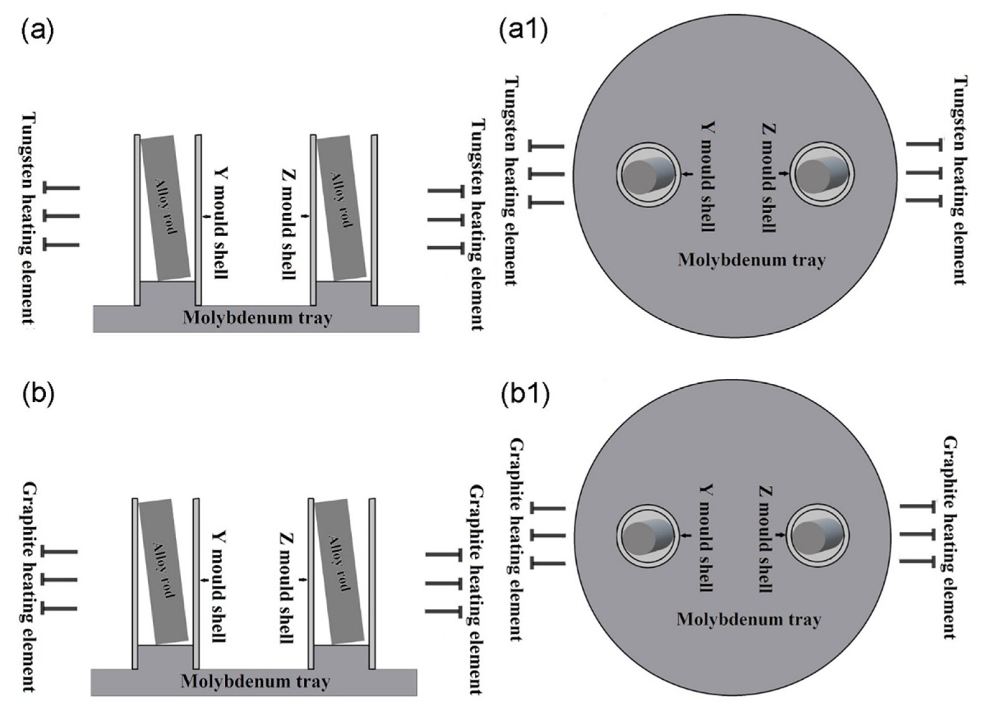
Figure 2.
Back-scattered electron (BSE) images of the microstructure of the as-cast master alloy under different magnifications: (a) 200× and (b) 1000×.
Figure 2.
Back-scattered electron (BSE) images of the microstructure of the as-cast master alloy under different magnifications: (a) 200× and (b) 1000×.

Figure 3.
XRD (X-ray diffraction) patterns of the master alloy.
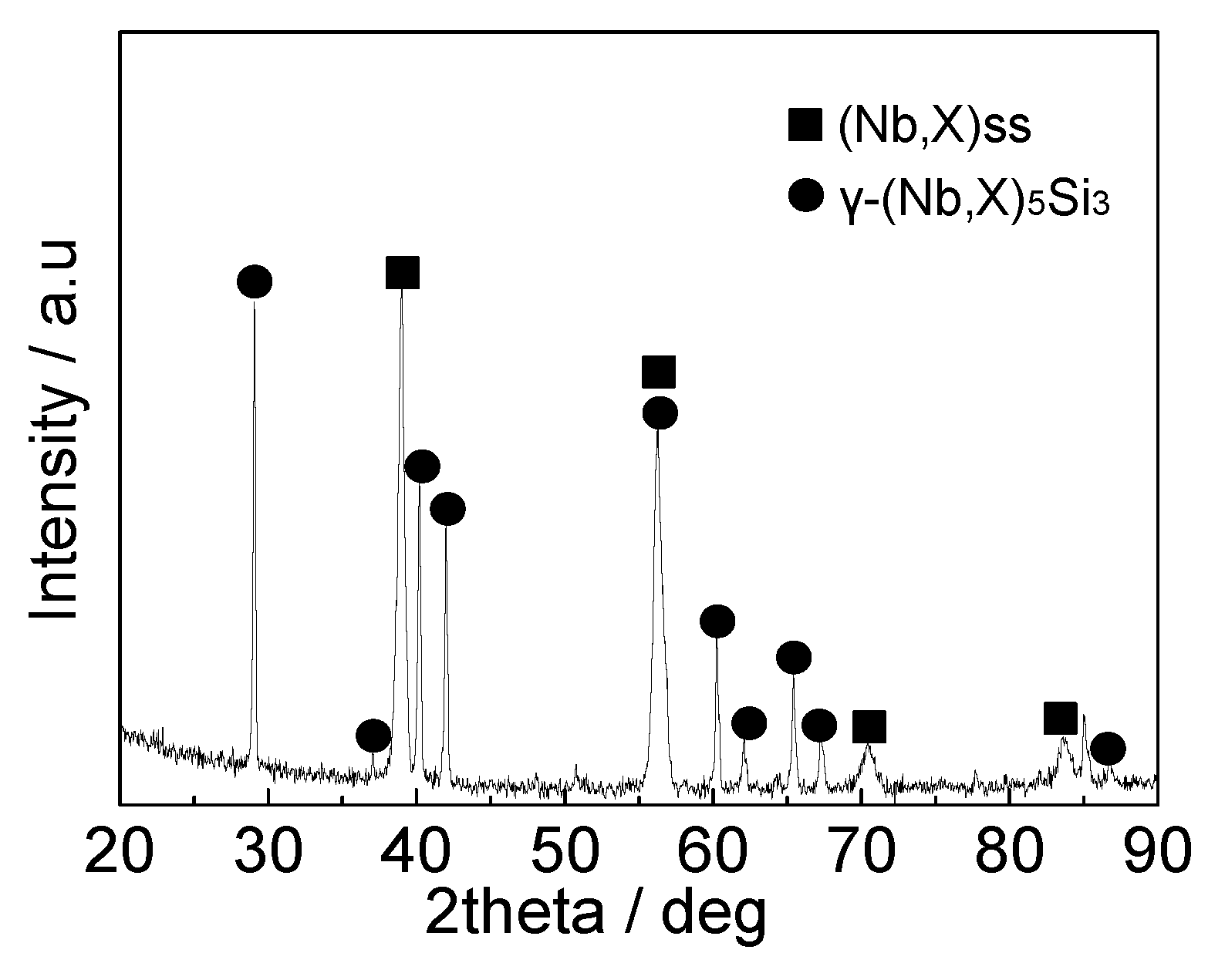
Figure 4.
Macromorphologies of the samples after re-melting at 1850 °C for 30 min in a vacuum furnace with a tungsten heating element: (a) cross section and (b) lateral surface of the re-melted alloy in the Y mold shell; (c) cross section and (d) lateral surface of the re-melted alloy in the Z mold shell.
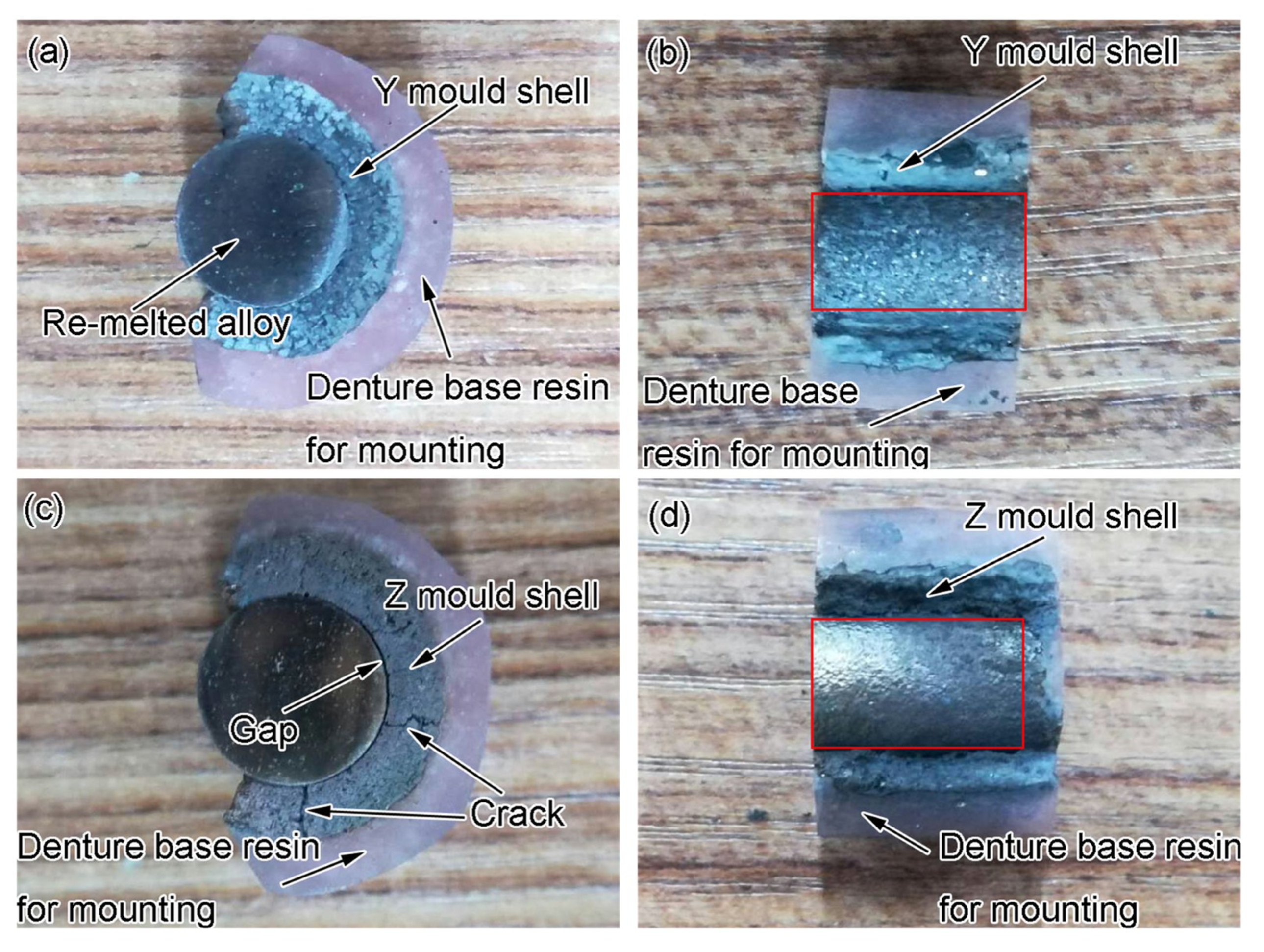
Figure 5.
XRD patterns of the lateral surface of the re-melted alloy: (a) Y and Z samples in a vacuum furnace with a tungsten heating element and (b) Y sample in a vacuum furnace with a graphite heating element.
Figure 5.
XRD patterns of the lateral surface of the re-melted alloy: (a) Y and Z samples in a vacuum furnace with a tungsten heating element and (b) Y sample in a vacuum furnace with a graphite heating element.
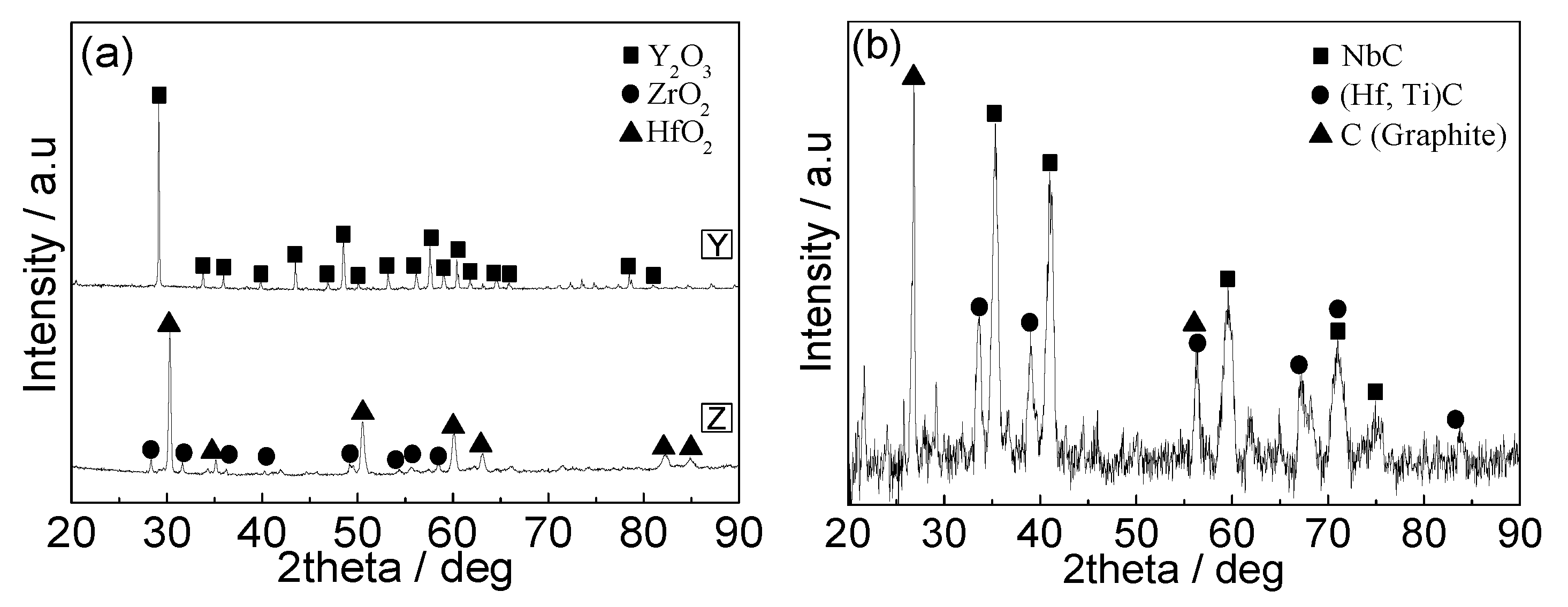
Figure 6.
Macrophotographs of the samples after re-melting at 1850 °C for 30 min in a vacuum furnace with a graphite heating element: (a) cross section of the Y sample, (b) cross section of the Z sample, (c) untreated primitive Y sample and (d) lateral surface of the re-melted alloy in the Y mold shell.
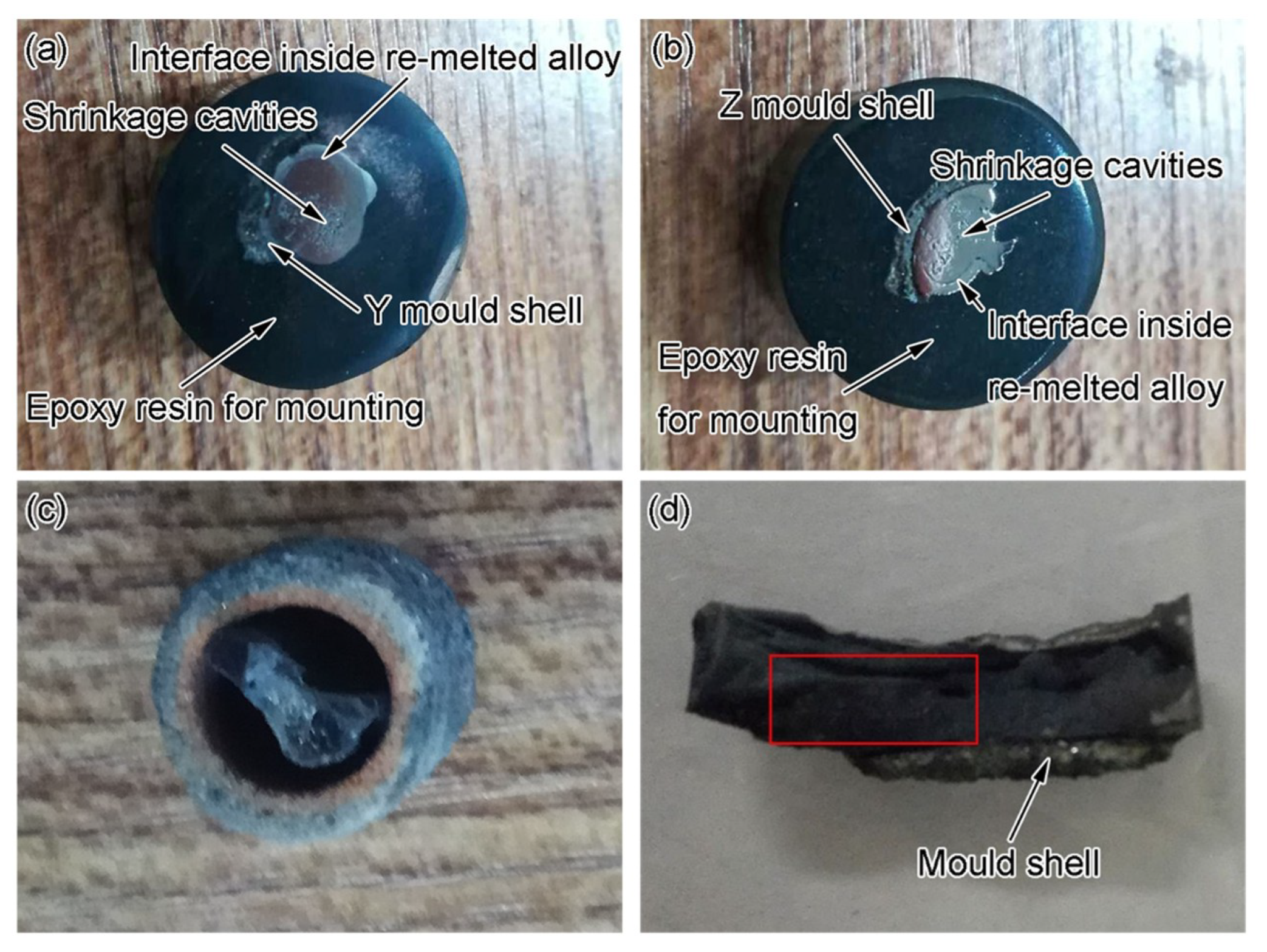
Figure 7.
BSE images of the Nb–Si-based alloy re-melted in: (a) Y and (b) Z mold shells in a vacuum furnace with a tungsten heating element and (c) Y and (d) Z mold shells in a vacuum furnace with a graphite heating element.
Figure 7.
BSE images of the Nb–Si-based alloy re-melted in: (a) Y and (b) Z mold shells in a vacuum furnace with a tungsten heating element and (c) Y and (d) Z mold shells in a vacuum furnace with a graphite heating element.
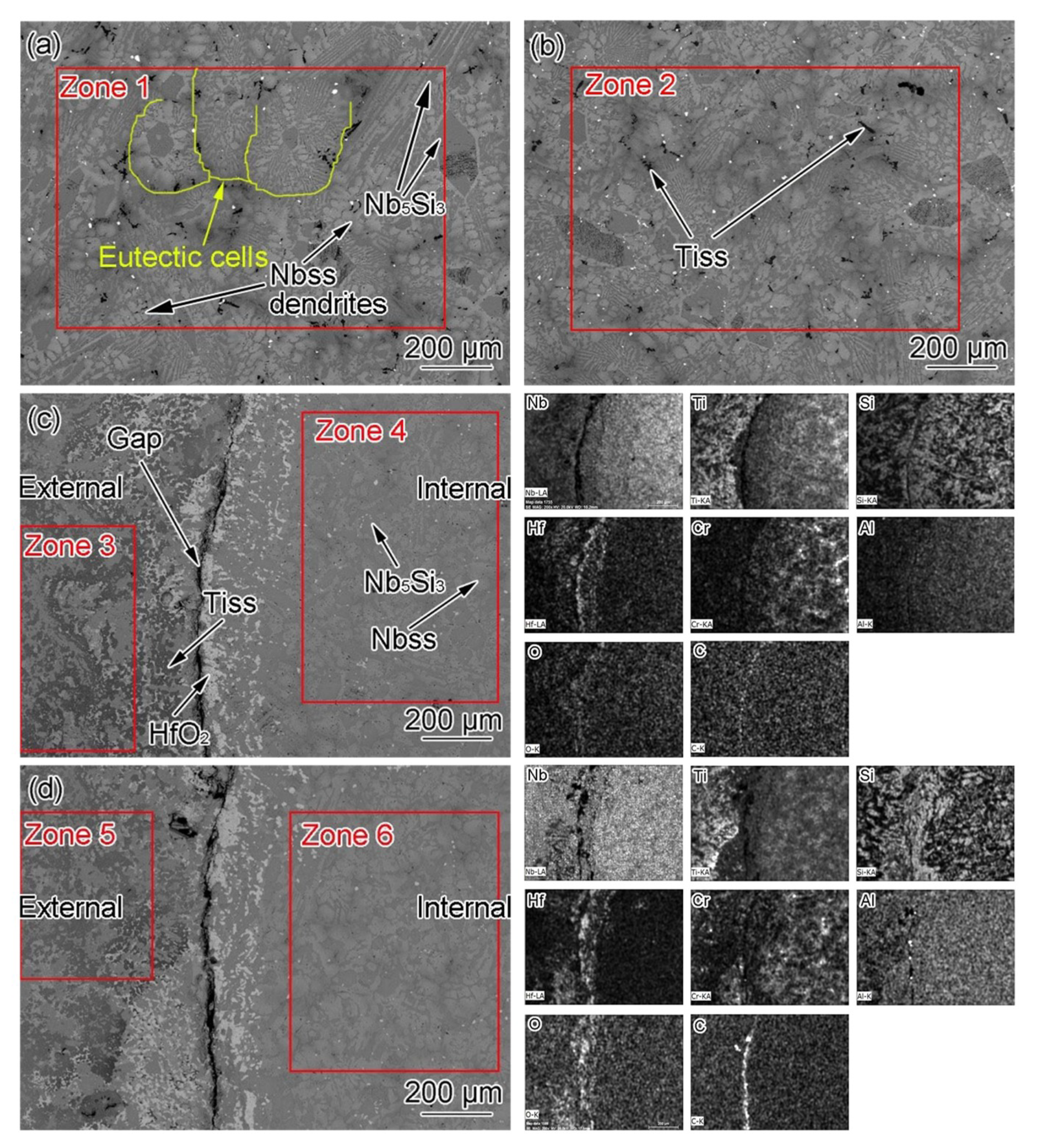
Figure 8.
XRD patterns of the alloy re-melted in Z and Y mold shells in a vacuum furnace with (a) a tungsten and (b) a graphite heating element.
Figure 8.
XRD patterns of the alloy re-melted in Z and Y mold shells in a vacuum furnace with (a) a tungsten and (b) a graphite heating element.
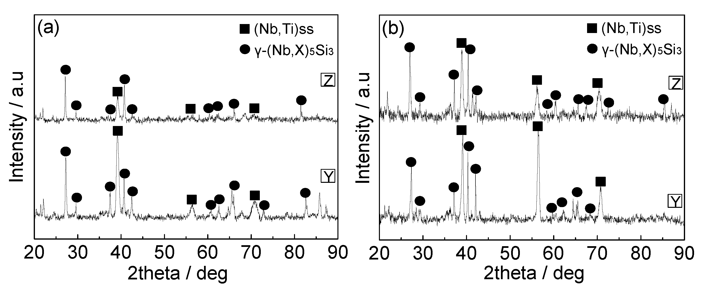
Figure 9.
Morphologies of the interfaces between the alloy and the mold shells in: (a) Y and (b) Z samples after re-melting in a vacuum furnace with a tungsten heating element and (c) Y and (d) Z samples after re-melting in a vacuum furnace with a graphite heating element.
Figure 9.
Morphologies of the interfaces between the alloy and the mold shells in: (a) Y and (b) Z samples after re-melting in a vacuum furnace with a tungsten heating element and (c) Y and (d) Z samples after re-melting in a vacuum furnace with a graphite heating element.
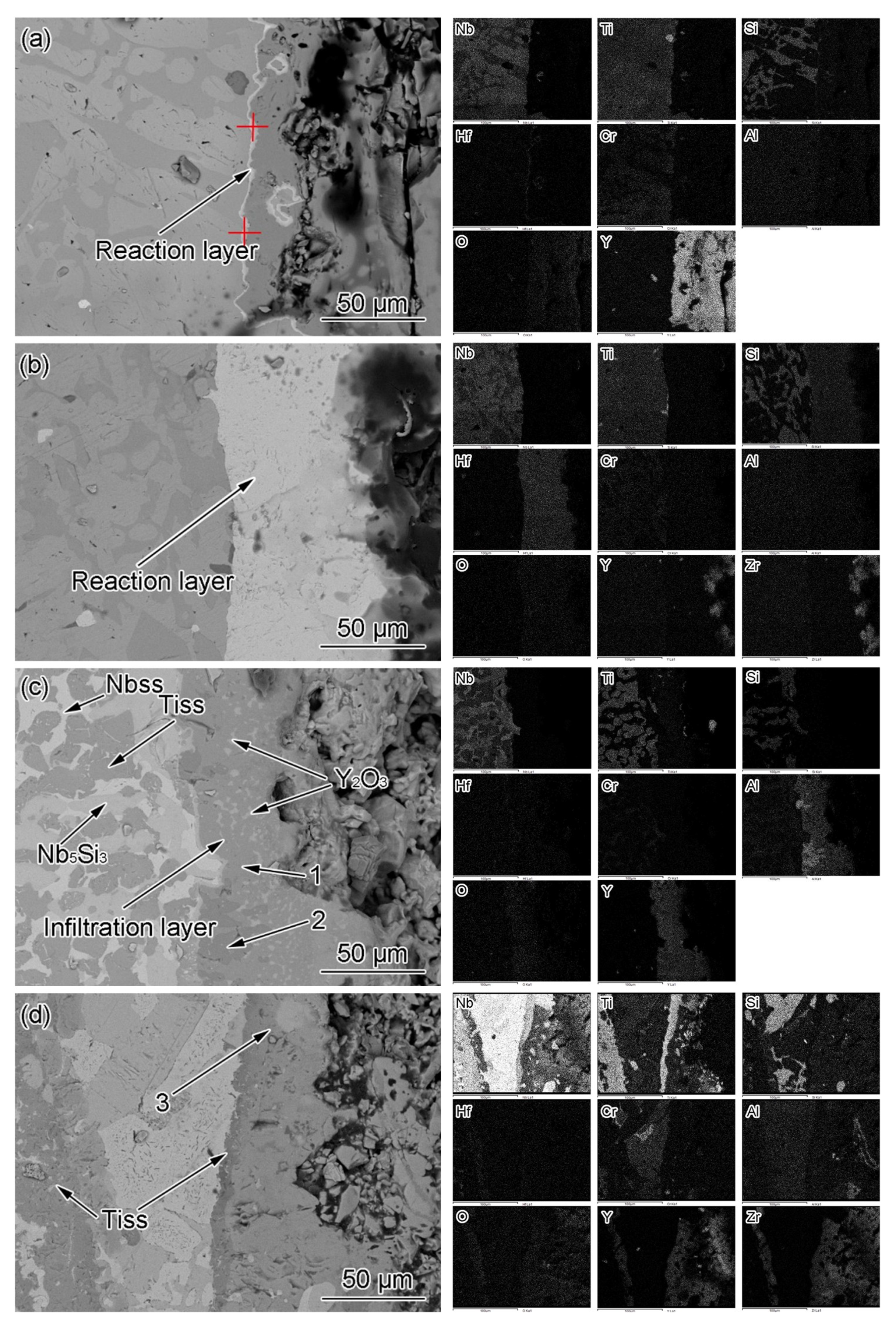
Figure 10.
Standard Gibbs free energy change ΔGθ of the reactions between C and Nb, Ti, and Hf.
Figure 11.
Schematic drawings of the re-melting process of Nb–Si-based ultrahigh-temperature alloy in the furnace with a graphite heating element.
Figure 11.
Schematic drawings of the re-melting process of Nb–Si-based ultrahigh-temperature alloy in the furnace with a graphite heating element.
Figure 12.
Variation of the activity coefficients of the elements Nb, Ti, and Si with changes in the carbon concentration in the systems (a) Nb–Ti–C and (b) Nb–Si–C.
Figure 12.
Variation of the activity coefficients of the elements Nb, Ti, and Si with changes in the carbon concentration in the systems (a) Nb–Ti–C and (b) Nb–Si–C.

Table 1.
Composition of the zones marked in Figure 8, determined by EDS (energy dispersive spectroscopy) mapping analysis.
Table 1.
Composition of the zones marked in Figure 8, determined by EDS (energy dispersive spectroscopy) mapping analysis.
| Zones | Compositions/% | |||||||
|---|---|---|---|---|---|---|---|---|
| Nb | Ti | Si | Hf | Cr | Al | O | C | |
| 1 | 28.87 | 11.96 | 9.66 | 1.53 | 2.51 | 1.70 | 14.17 | 29.60 |
| Re-normalization | 51.48 | 21.17 | 17.28 | 2.63 | 4.41 | 3.02 | - | - |
| 2 | 25.10 | 9.65 | 6.55 | 0.78 | 2.06 | 1.51 | 14.38 | 39.96 |
| Re-normalization | 54.98 | 21.14 | 14.35 | 1.71 | 4.51 | 3.31 | - | - |
| 3 | 21.84 | 8.99 | 5.25 | 0.29 | 2.34 | 0.91 | 7.13 | 53.25 |
| Re-normalization | 55.12 | 22.70 | 13.25 | 0.73 | 5.91 | 2.29 | - | - |
| 4 | 23.37 | 7.94 | 6.50 | 0.33 | 2.78 | 1.63 | 7.09 | 50.36 |
| Re-normalization | 54.92 | 18.66 | 15.28 | 0.78 | 6.53 | 3.83 | - | - |
| 5 | 22.20 | 9.33 | 4.88 | 0.47 | 2.25 | 1.12 | 8.73 | 51.02 |
| Re-normalization | 55.16 | 23.18 | 12.12 | 1.17 | 5.59 | 2.78 | - | - |
| 6 | 25.27 | 8.24 | 6.95 | 0.39 | 2.71 | 1.47 | 7.47 | 47.51 |
| Re-normalization | 56.12 | 18.30 | 15.43 | 0.87 | 6.02 | 3.26 | - | - |
Table 2.
Interface and near-interface characteristics of the samples.
| Mold Shells | Furnace Heating Element | Phase Composition | Position | Thickness/μm | Formation Mode |
|---|---|---|---|---|---|
| Y | Tungsten | HfO2 + Y2O3 | On the interface | 1.5 | Interface reaction |
| Z | Tungsten | HfO2 | On the interface | 58.1 | Interface reaction |
| Y | Graphite | Y2O3 + Y–Al and Y–Ti composite oxides | In Y mold shell adjacent to interface | - | Infiltration reaction |
| Z | Graphite | ZrO2 + Zr–Ti composite oxides | In Z mold shell adjacent to interface | - | Infiltration reaction |
© 2019 by the authors. Licensee MDPI, Basel, Switzerland. This article is an open access article distributed under the terms and conditions of the Creative Commons Attribution (CC BY) license (http://creativecommons.org/licenses/by/4.0/).
Share and Cite
MDPI and ACS Style
Wang, Y.; Guo, X. Re-Melting Nb–Si-Based Ultrahigh-Temperature Alloys in Ceramic Mold Shells. Metals 2019, 9, 721. https://doi.org/10.3390/met9070721
AMA Style
Wang Y, Guo X. Re-Melting Nb–Si-Based Ultrahigh-Temperature Alloys in Ceramic Mold Shells. Metals. 2019; 9(7):721. https://doi.org/10.3390/met9070721
Chicago/Turabian StyleWang, Yin, and Xiping Guo. 2019. "Re-Melting Nb–Si-Based Ultrahigh-Temperature Alloys in Ceramic Mold Shells" Metals 9, no. 7: 721. https://doi.org/10.3390/met9070721
Note that from the first issue of 2016, this journal uses article numbers instead of page numbers. See further details here.