Accuracy and Surface Quality Improvements in the Manufacturing of Ti-6Al-4V Parts Using Hot Single Point Incremental Forming


Abstract
:1. Introduction
2. Materials and Methods
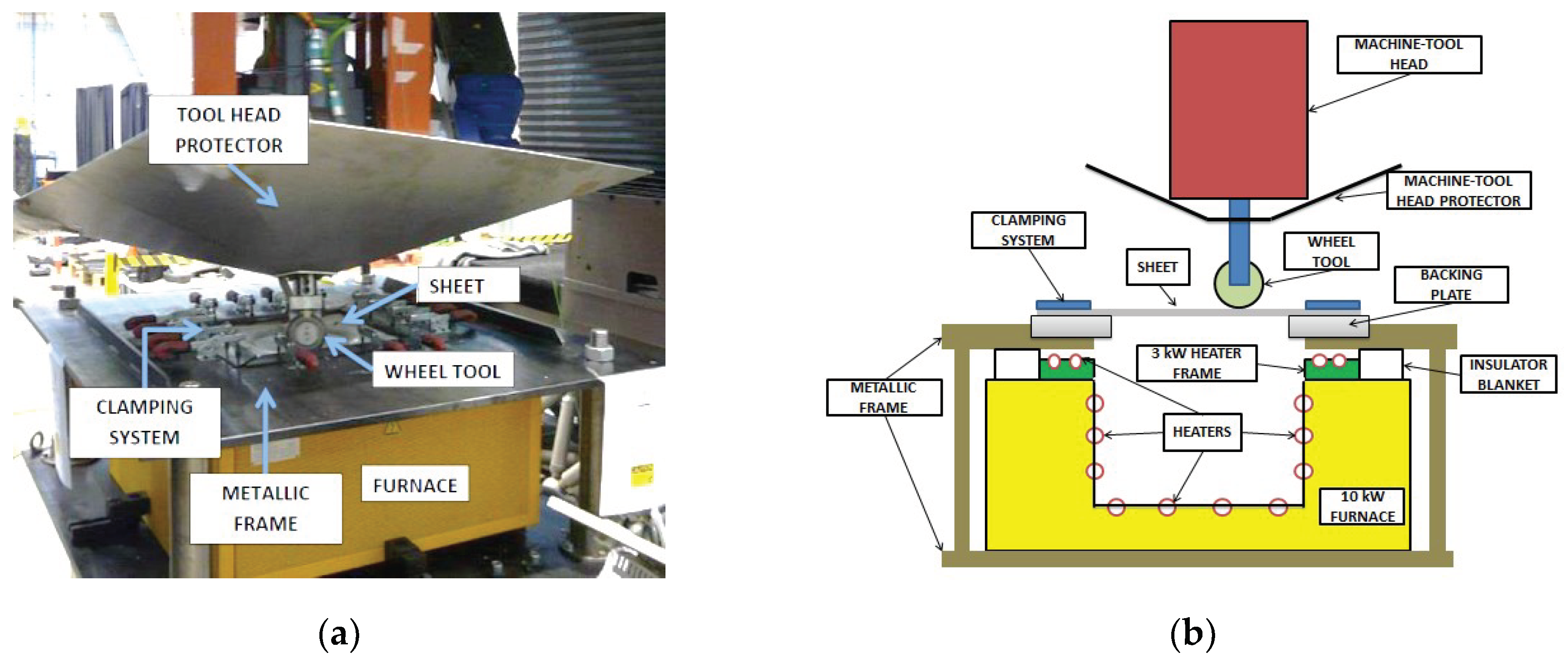
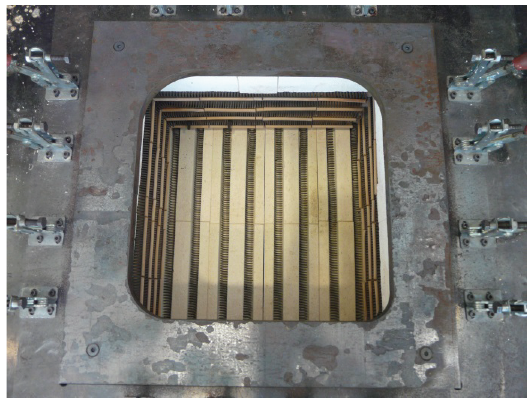
2.1. Experimental Set up
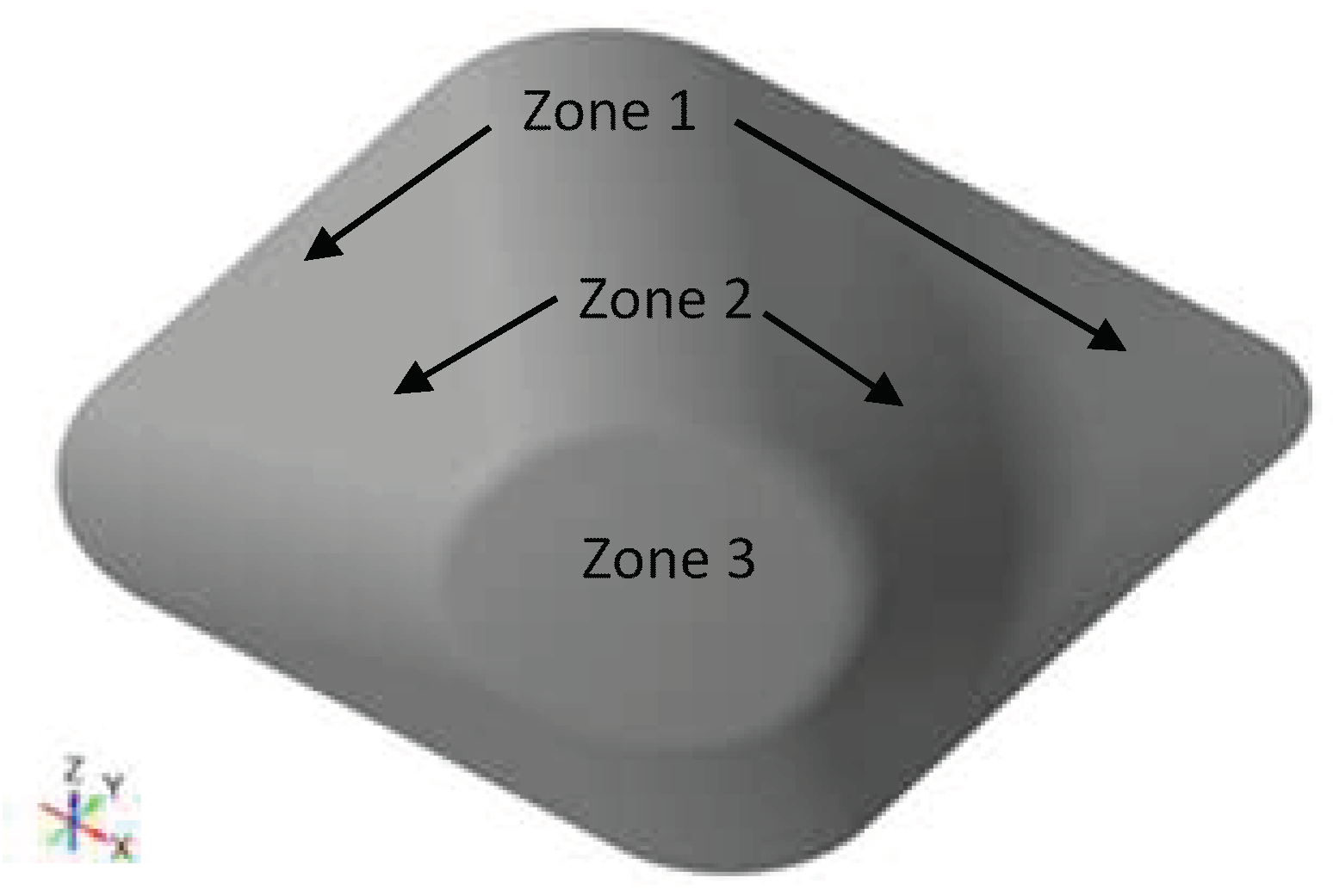
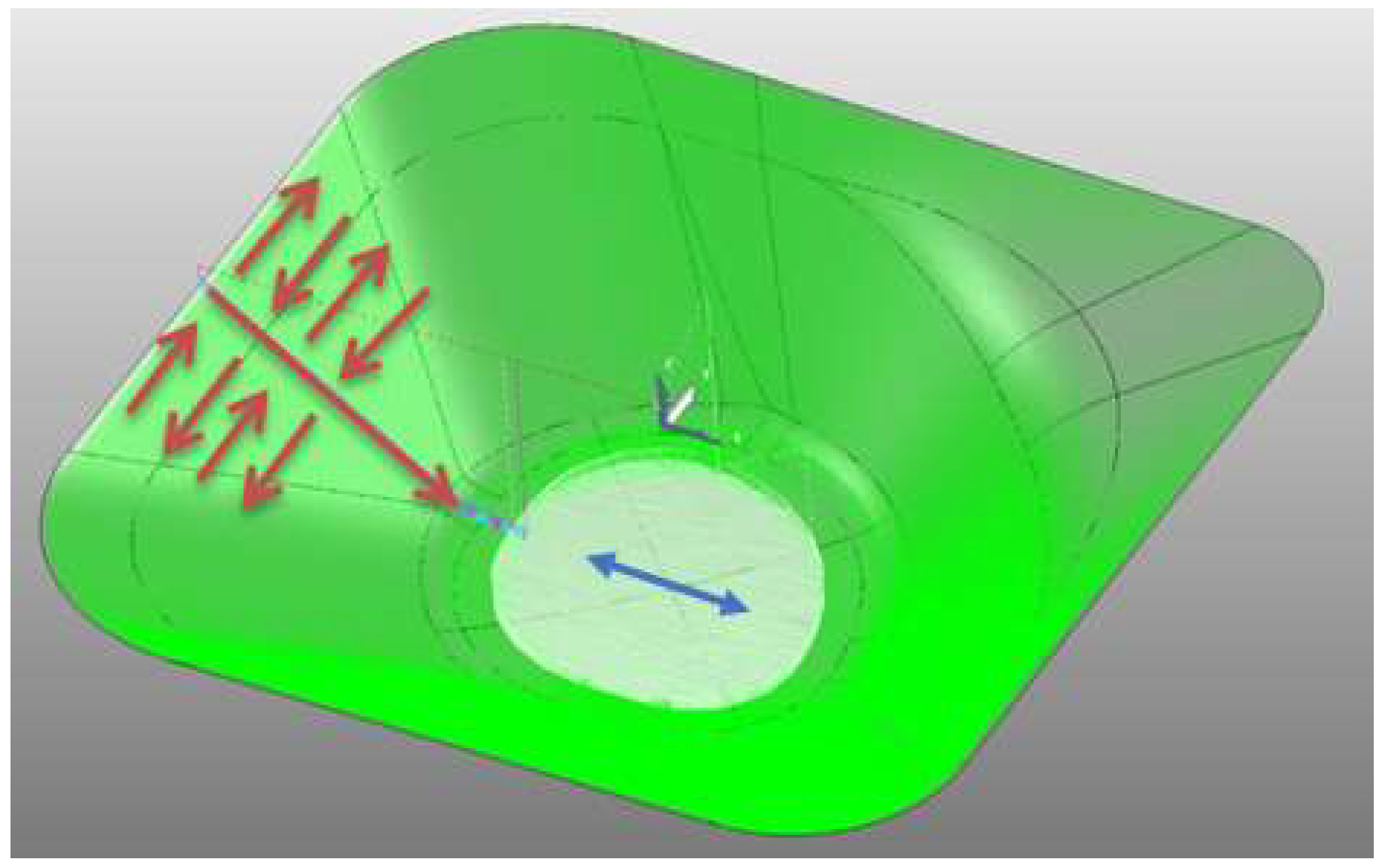
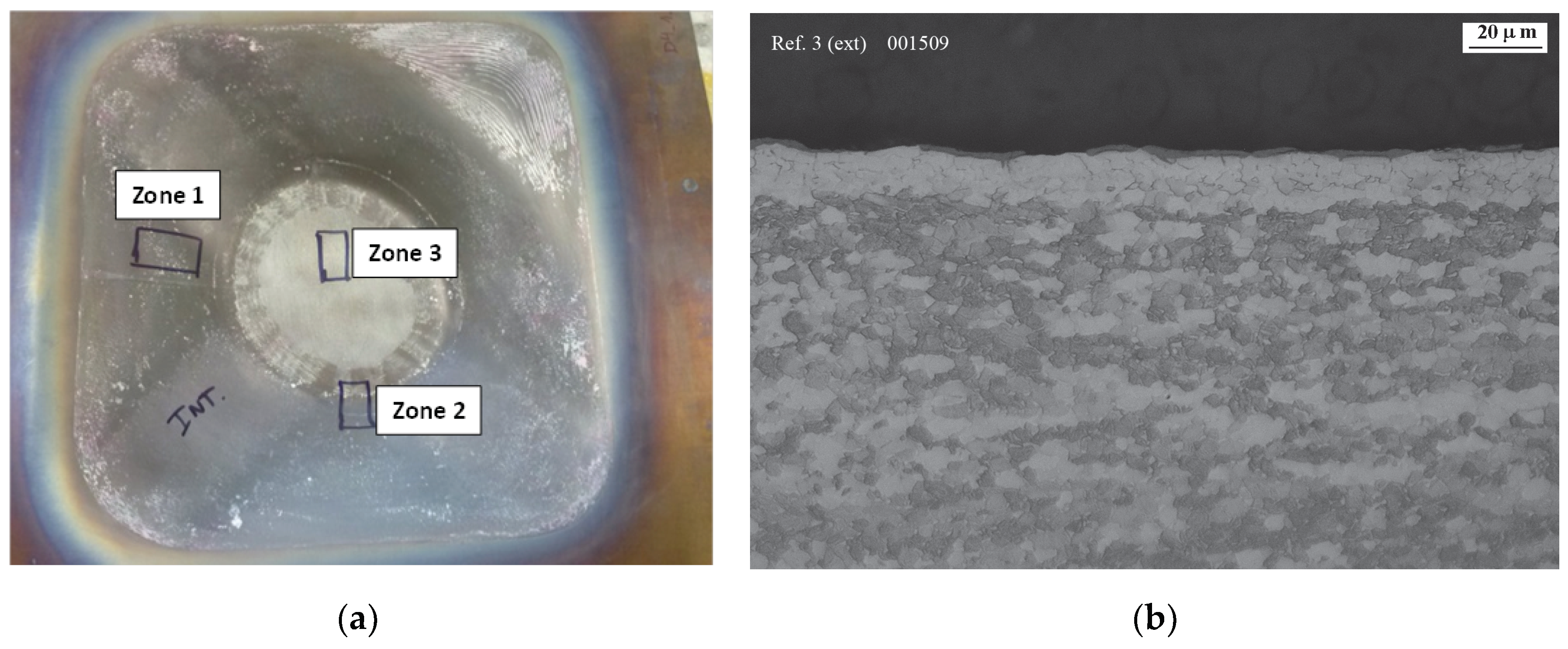
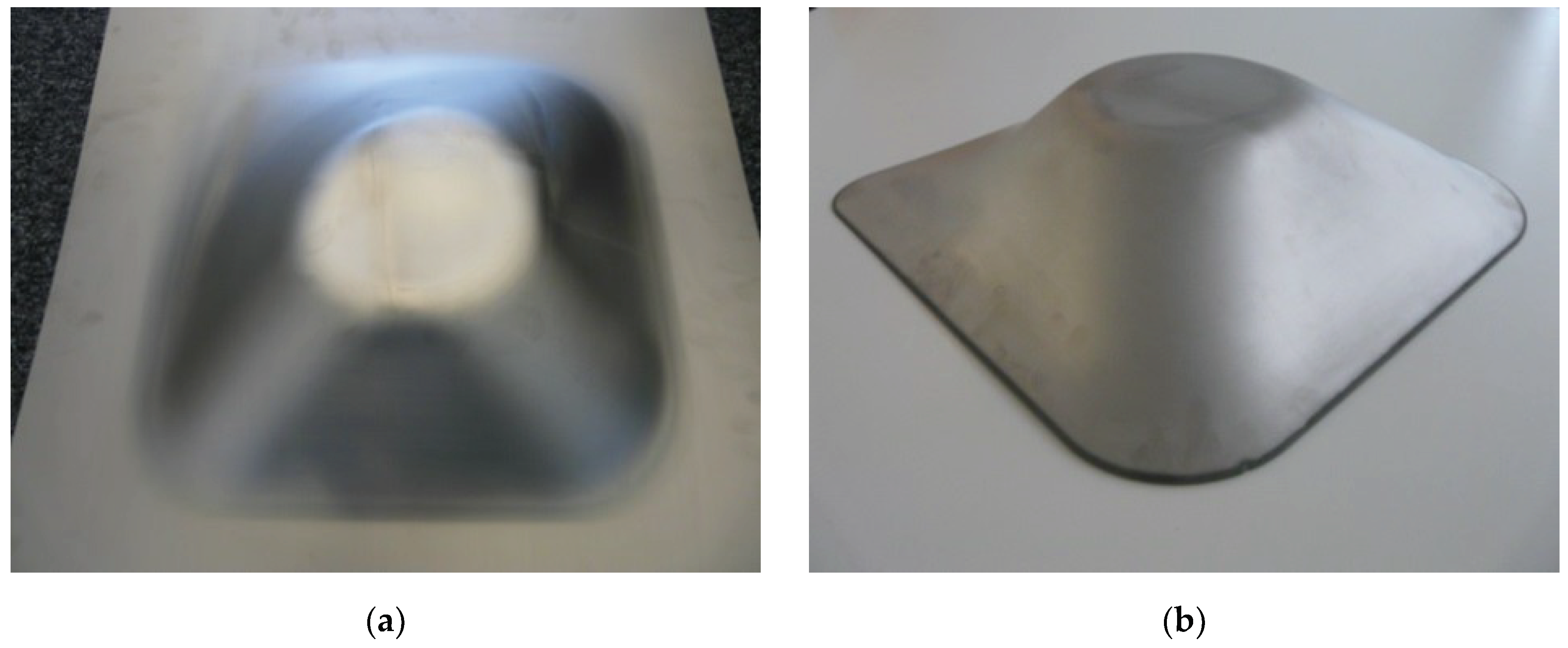
- Zone 1: 15 mm depth section with a transition zone with drastic a wall angle variation (from 9° to 35°).
- Zone 2: 50 mm depth section with almost constant wall angle (35°–39°).
- Zone 3: lower surface with slight curvature (5 mm between upper and lower zone).
2.2. Experimental Work
2.2.1. Working Variables
- Heating: heating ramp from room temperature up to the selected forming temperature (2 h).
- Forming: hot SPIF to produce the part using the selected process parameters.
- Cooling: controlled cooling down without unclamping the sheet and according to stress relief conditions recommended by Donachie [1]. To obtain optimal conditions regarding the stress relief, after the forming stage, the part was covered with the thermally insulated cover.
2.2.2. Tool Path Correction
- Input a CAD-generated coordinate cloud.
- Pre-processed the coordinate cloud to produce an input data set.
- After pre-processing, the data was passed to a classification module where a classifier was applied to each record (representing a grid square) in the data set to predict the associated springback error.
- The predicted springback was then applied to the CAD cloud and a modified CAD shape was produced.
- The predicted cloud was then used to generate a corrected cloud. The corrected cloud was generated by applying the predicted error at each point in the grid in the opposite direction to the predicted direction.
- Smoothing was applied to the corrected cloud so as minimize gaps and bandings to produce a smooth corrected cloud that can used for tool path programming.
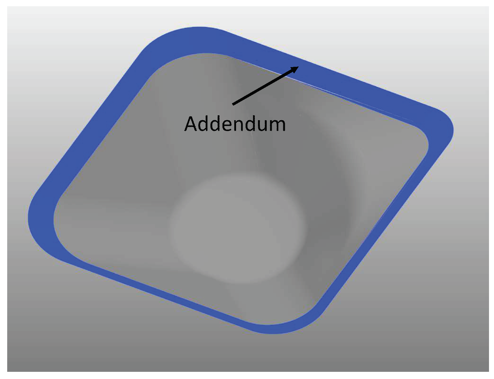
2.2.3. Introduction of an Addendum to the Target Geometry
2.3. Finishing Operations
3. Results
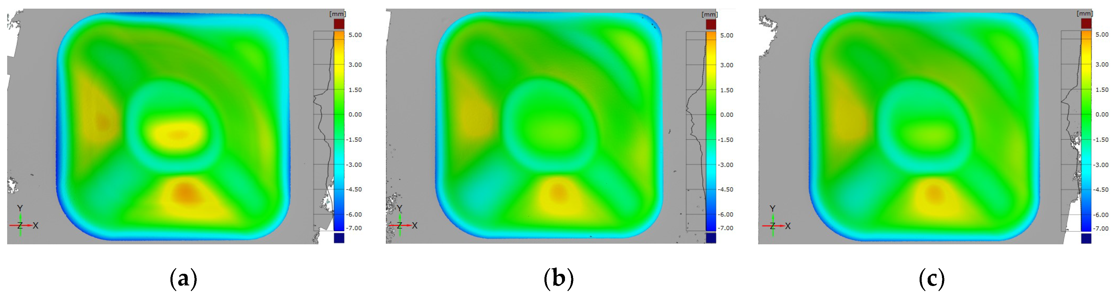
3.1. Influence of the Working Temperature on the Geometric Accuracy
- By increasing the temperature, positive underforming deviations at the flat/low curvature areas decreased due to the reduction effect of temperature on material springback.
- Higher temperature led to an increase of the negative overforming at the most severely affected area, that with an abrupt wall angle variation, because of the lower stiffness of the material with the temperature increased. However, overforming in the remaining perimeter area seemed to decrease with temperature. The difference in the behavior could be explained by the geometric effect. Because the bending radius around the perimeter is higher than in the other zone, the temperature increase could have a positive effect on the springback associated to bending.
- Differences between values obtained at 675 °C and 700 °C seem small.
3.2. Improvement of the Geometric Accuracy
3.2.1. Influence of the Toolpath Correction
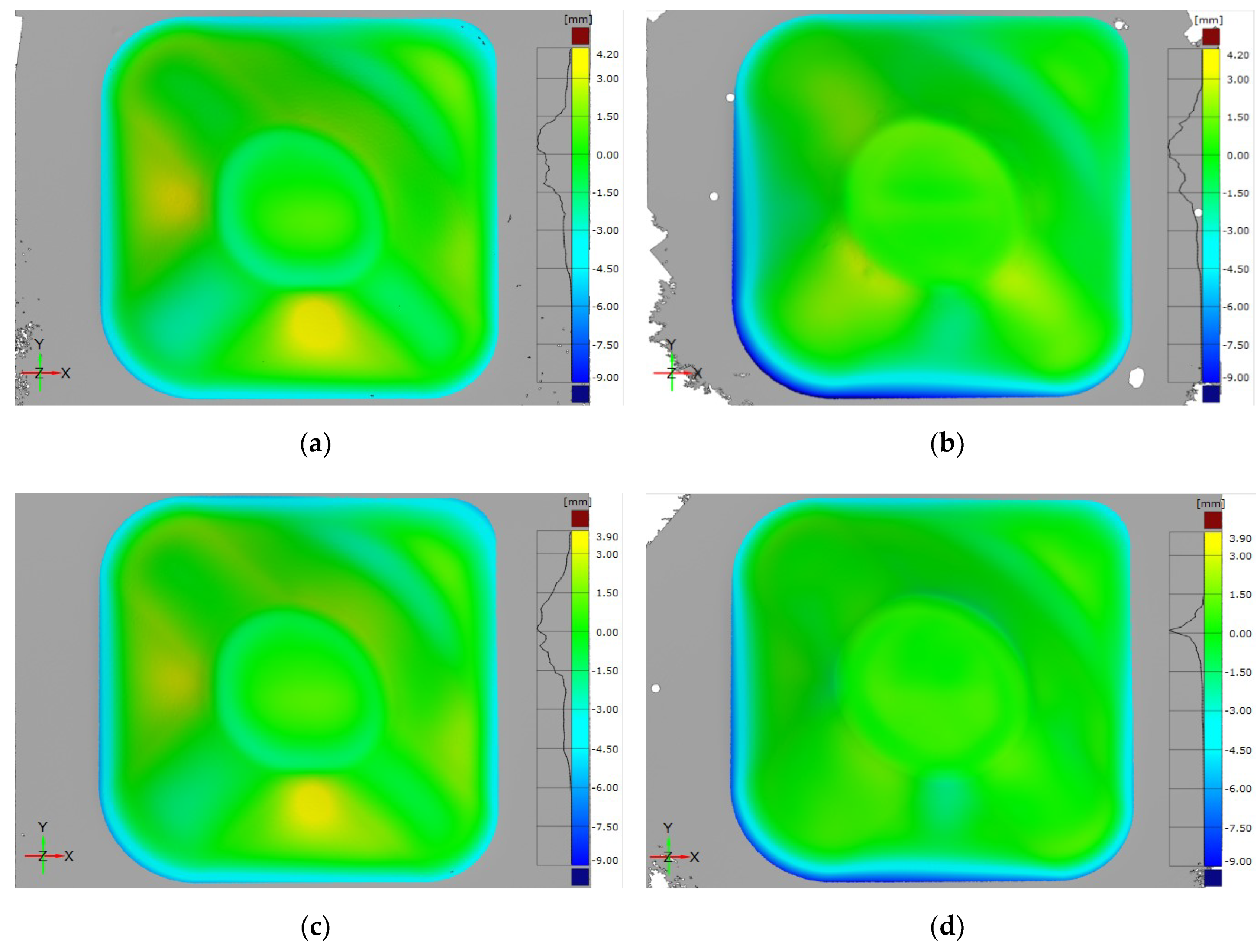
- Corrected parts showed identical deviation patterns:
- ⚬
- Slight negative overforming at the flat walls area.
- ⚬
- Positive underforming at the edges that intersect the part walls.
- ⚬
- Low deviation at the low curvature bottom area.
- ⚬
- Negative overforming region over both the perimeter and the abrupt wall angle variation areas.
- A quantitative analysis of the deviation values points out that the tool path correction led to:
- ⚬
- Shifting of the deviation at flat walls from positive underforming to negative overforming and the absolute values decreased considerably (peak values varying from +4.00 to −2.00 mm approximately).
- ⚬
- Shifting of the deviation at the edges that intersect part walls from negative overforming to positive underforming without much variation in the deviation absolute values (peak values around ±2.00 mm).
- ⚬
- Shifting of the location of the maximum positive underforming deviations from flat walls to the edges that intersected these walls (underforming peak values 40–61% lower).
- ⚬
- Significant decrease of the deviation of the low curvature bottom and with lower variation (from −2.00/+1.50 mm to −0.50/+1.00 mm).
- ⚬
- Low variation in the magnitude of the deviations over the abrupt wall angle variation area.
- ⚬
- Significant increase of the deviations magnitude over the perimeter area (peak values 44–68% higher).
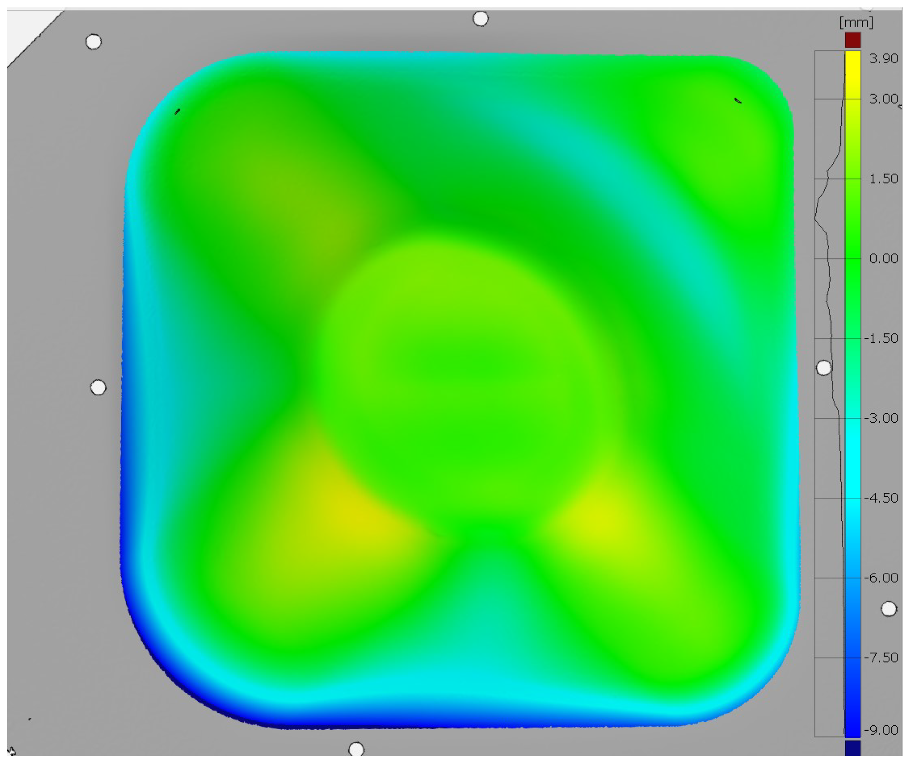
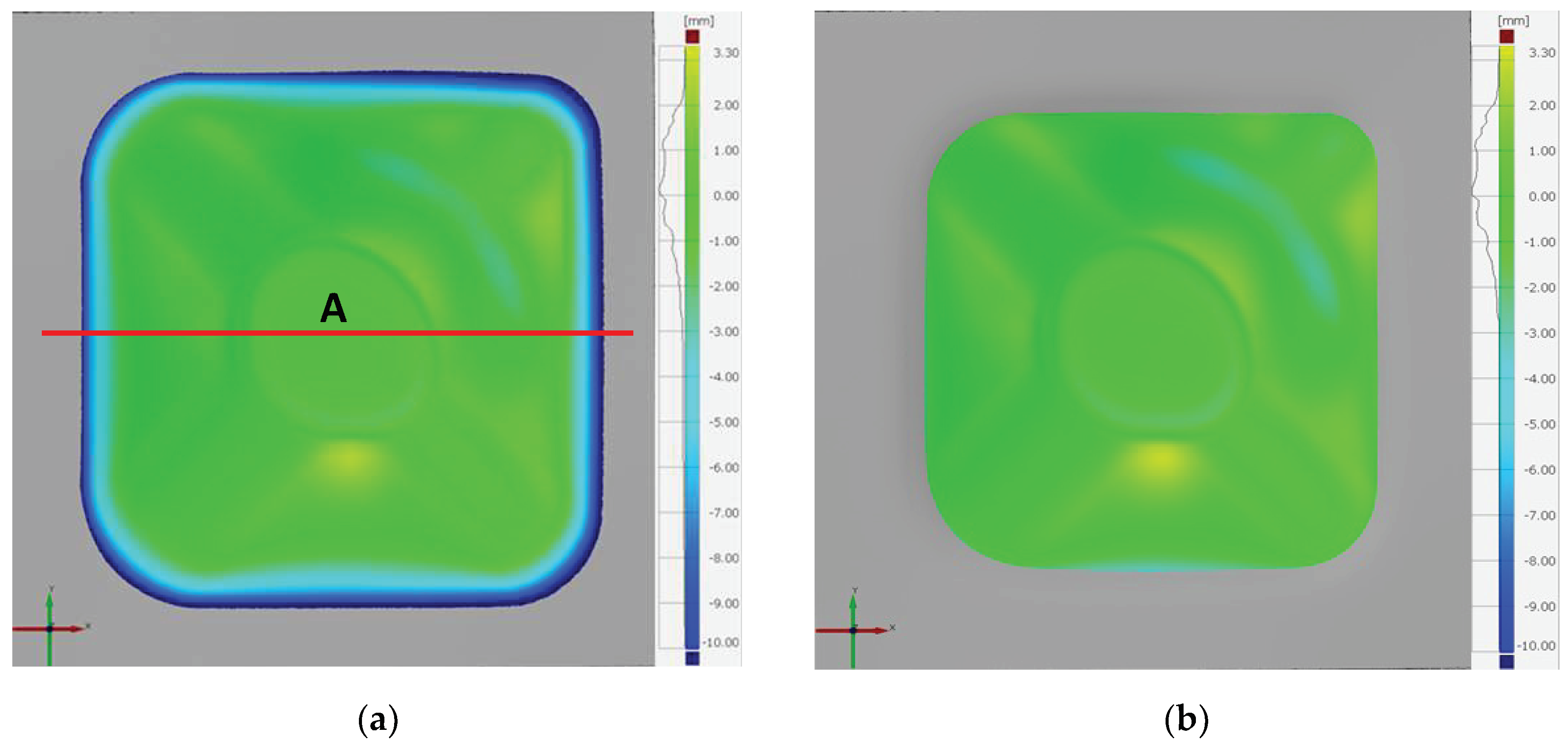
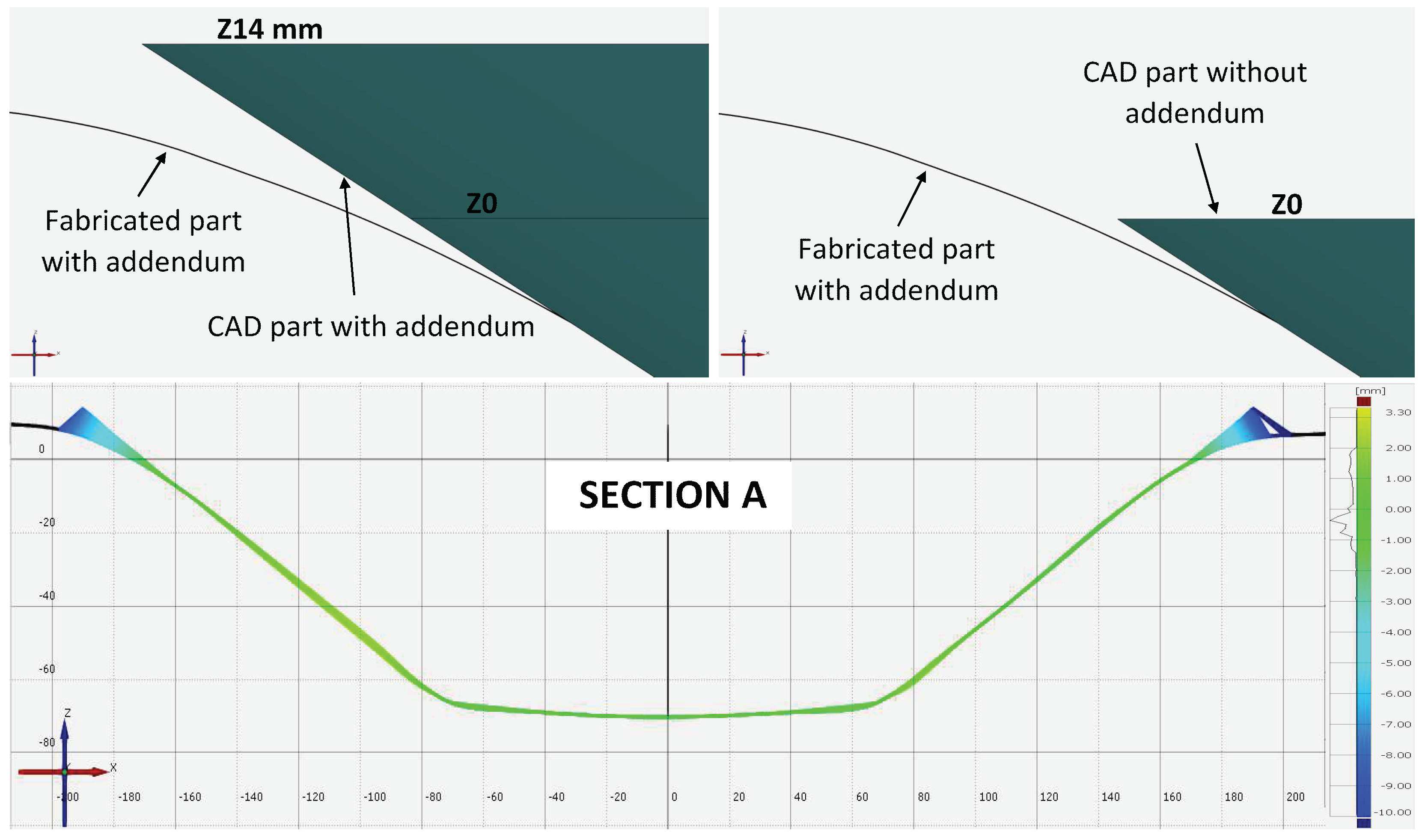
3.2.2. Influence of the Introduction of an Addendum
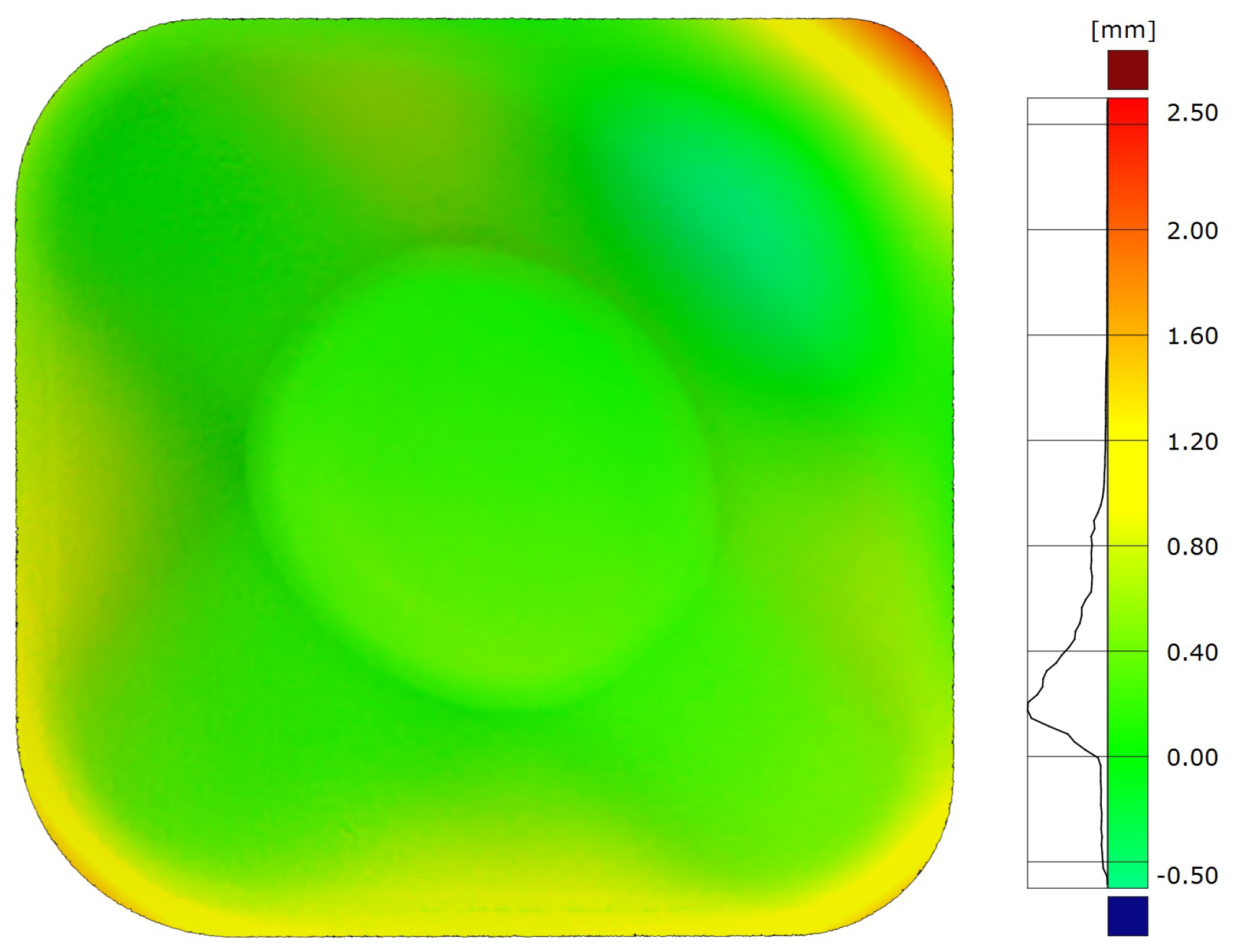
- All deviations lying in the addendum zone are negative overforming deviations. This is clearly shown in Figure 14, where the deviation profile of a section extracted from the deviation map of the part fabricated with addendum (Figure 13a) is depicted. That is, the entire addendum depth (14 mm) was affected by deflection. On the contrary, over the target geometry, the effect of the deflection was drastically reduced. In this sense, on the target geometry, the maximum negative overforming deviation was almost 70% lower than in the geometry containing the addendum.
- The deviations over the addendum represented around 63% of the whole negative overforming deviations along the part.
- On the target geometry, the percentage of deviations within the range ±1 mm was 21% higher than in the geometry containing the addendum. This value can be considered an indicator of the negative influence of the bending effect over the geometric accuracy of the part.
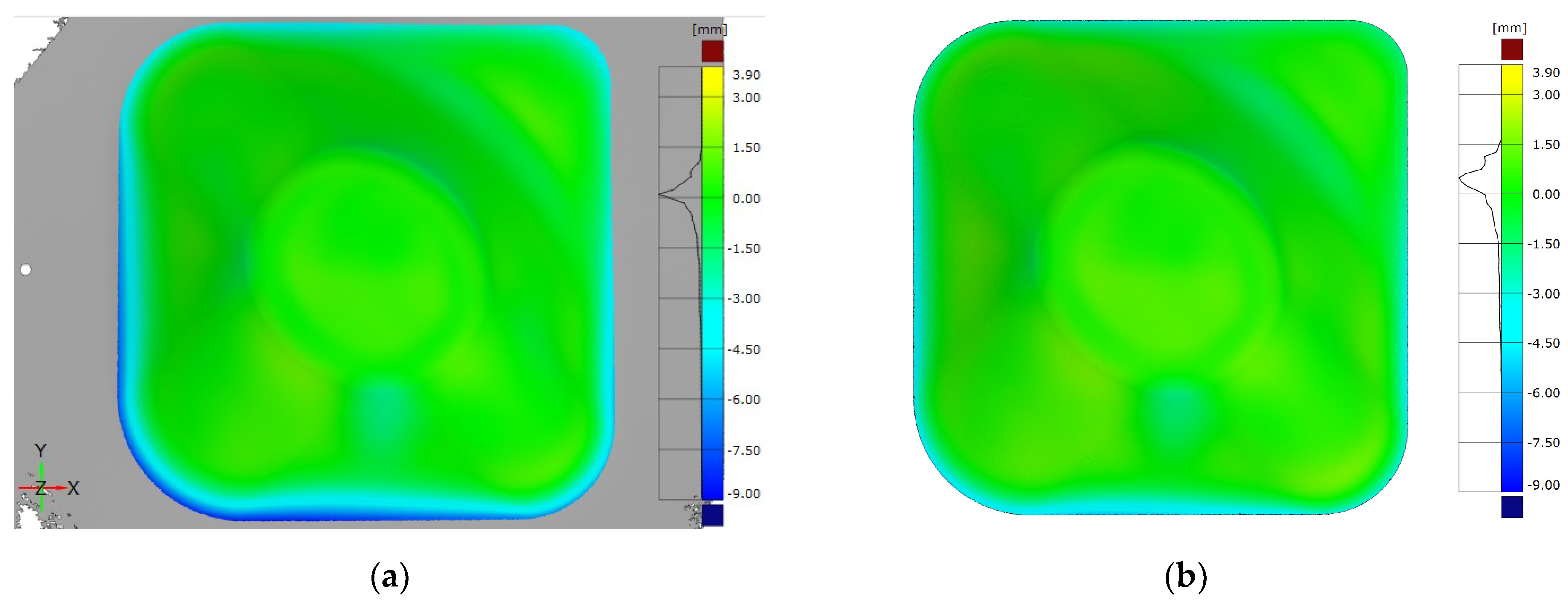
3.3. Analysis of the Finishing Operations
- The negative overforming deviations decreased (peak value 3.39 mm and average value 0.35 mm lower).
- On the contrary, the positive underforming deviations increased (peak value 0.21 mm and average value 0.17 mm higher).
- The percentage of deviations within ±1 mm remained almost constant since the decrease of the overforming deviations compensated for the increase of the underforming deviations.
4. Discussion
- The analysis of the influence of the working temperature on the geometric accuracy by means of a preliminary set of SPIF trials.
- The application of toolpath correction strategies to improve the geometric accuracy of Ti-6Al-4V parts.
- The development of a novel solution to eliminate deviations associated with the bending of the sheet along the perimeter on the part.
- The analysis of the influence of two finishing operations (decontamination and trimming) on the final geometric accuracy of the part.
5. Conclusions
- The application of the IPM leads to an accuracy improvement up to 49%.
- The IPM is effective to counteract deviations associated with the springback effect. However, it is not effective to correct deviations located at the perimeter area of the part associated to the sheet deflection.
- The employed coordinate cloud to generate the classifier of the IPM significantly influences the final accuracy of the part after correction.
- Deviations over the addendum, all affected by deflection, represent around 63% of the whole negative overforming deviations along the part.
- The negative effect of the deflection of the sheet over the geometric accuracy can be quantify in 21%.
- On the target geometry, the overforming negative deviations are 50% minimized and a 25.4% accuracy improvement is achieved with the introduction of the addendum.
Author Contributions
Funding
Acknowledgments
Conflicts of Interest
References
- Donachie, M.J. Titanium: A Technical Guide, 2nd ed.; ASM International, the Materials Information Society: Materials Park, OH, USA, 2004. [Google Scholar]
- Jeswiet, J.; Micari, F.; Hirt, G.; Bramley, A.; Duflou, J.; Allwood, J. Asymmetric single point incremental forming of sheet metal. CIRP Ann. 2005, 54, 88–114. [Google Scholar] [CrossRef]
- Lu, H.; Liu, H.; Wang, C. Review on strategies for geometric accuracy improvement in incremental sheet forming. Int. J. Adv. Manuf. Technol. 2019, 102, 3381–3417. [Google Scholar] [CrossRef]
- Ortiz, M.; Penalva, M.; Iriondo, E.; López de Lacalle, L.N. Investigation of thermal-related effects in hot SPIF of Ti–6Al–4V alloy. Int. J. Precis. Eng. Manuf. Green Technol. 2019. [Google Scholar] [CrossRef]
- Palumbo, G.; Brandizzi, M. Experimental investigations on the single point incremental forming of a titanium alloy component combining static heating with high tool rotation speed. Mater. Des. 2012, 40, 43–51. [Google Scholar] [CrossRef]
- Khazaali, H.; Fereshteh-Saniee, F. A comprehensive experimental investigation on the influences of the process variables on warm incremental forming of Ti-6Al-4V titanium alloy using a simple technique. Int. J. Adv. Manuf. Technol. 2016, 87, 2911–2923. [Google Scholar] [CrossRef]
- Naranjo, A.J.; Miguel, V.; Martínez, A.; Coello, J.; Manjabacas, C.M. Evaluation of the formability and dimensional accuracy improvement of Ti6Al4V in warm SPIF processes. Metals 2019, 9, 272. [Google Scholar] [CrossRef]
- Behera, A.K.; Verbert, J.; Lauwers, B.; Duflou, J.R. Tool path compensation strategies for single point incremental sheet forming using multivariate adaptive regression splines. Comput. Aided Des. 2013, 45, 575–590. [Google Scholar] [CrossRef]
- Behera, A.K.; Lauwers, B.; Duflou, J.R. Tool path generation framework for accurate manufacture of complex 3D sheet metal parts using single point incremental forming. Comput. Ind. 2014, 65, 563–584. [Google Scholar] [CrossRef]
- Fiorentino, A.; Giardini, C.; Ceretti, E. Application of artificial cognitive system to incremental sheet forming machine tools for part precision improvement. Precis. Eng. 2015, 39, 167–172. [Google Scholar] [CrossRef]
- Lu, H.; Kearney, M.; Liu, S.; Daniel, W.J.T.; Meehan, P.A. Two-directional toolpath correction in single-point incremental forming using model predictive control. Int. J. Adv. Manuf. Technol. 2017, 91, 91–106. [Google Scholar] [CrossRef]
- Khan, M.S.; Coenen, F.; Dixon, C.; El-Salhi, S.; Penalva, M.; Rivero, A. An intelligent process model: Predicting springback in single point incremental forming. Int. J. Adv. Manuf. Technol. 2015, 76, 2071–2082. [Google Scholar] [CrossRef]
- Zwierzycki, M.; Nicholas, P.; Thomsen, M.R. Localised and learnt applications of machine learning for robotic incremental sheet forming. In Humanizing Digital Reality: Design Modelling Symposium Paris 2017; De Rycke, K., Gengnagel, C., Baverel, O., Burry, J., Mueller, C., Nguyen, M.M., Rahm, P., Thomsen, M.R., Eds.; Springer: Singapore, 2018; pp. 373–382. [Google Scholar]
- Ortiz, M.; Penalva, M.L.; Puerto, M.J.; Homola, P.; Kafka, V. Hot single point incremental forming of Ti-6Al-4V alloy. Key Eng. Mater. 2014, 611, 1079–1087. [Google Scholar] [CrossRef]
- Young, D.; Jeswiet, J. Wall thickness variations in single-point incremental forming. Proc. Inst. Mech. Eng. Part B J. Eng. Manuf. 2004, 218, 1453–1459. [Google Scholar] [CrossRef]


| Test | T Sheet (°C) | T Sheet/Tm * | Comment |
|---|---|---|---|
| D1 | 540 | 0.33 | Recommended minimal temperature for hot forming Ti-6Al-4V [1] |
| D2 | 675 | 0.41 | Temperature close to the limit of the heating equipment. |
| D3 | 700 | 0.42 | Top working temperature of the heating equipment. |
| Point | Zone 1 | Zone 2 | Zone 3 | |||
|---|---|---|---|---|---|---|
| Out (µm) | Inn (µm) | Out (µm) | Inn (µm) | Out (µm) | Inn (µm) | |
| 1 | 5.8 | 3.6 | 7.8 | 7.6 | 13.2 | 9.2 |
| 2 | 6.0 | 7.0 | 8.8 | 5.6 | 12.8 | 10.6 |
| 3 | 6.8 | 6.4 | 14.2 | 9.4 | 14.6 | 12.8 |
| 4 | 6.6 | 5.4 | 10.2 | 12.8 | 15.6 | 6.8 |
| 5 | 6.8 | 6.8 | 9.0 | 8.2 | 13.6 | 8.6 |
| Average | 6.4 | 6.1 | 10 | 8.7 | 14 | 9.6 |
| Trial | Max + (mm) | Max − (mm) | Average + (mm) | Average − (mm) | ±1 mm (%) |
|---|---|---|---|---|---|
| D1 | 4.71 | −6.89 | 1.35 | −2.21 | 40.2 |
| D2 | 4.18 | −5.96 | 1.08 | −1.64 | 48.7 |
| D3 | 4.18 | −6.14 | 1.18 | −1.67 | 44.9 |
| D2 Deviation Values (Three Iterations) | Average | Std Dev | Var Coeff (%) |
|---|---|---|---|
| Part deviations within 1 mm range (%) | 47.3 | 1.5 | 3.2 |
| Max positive deviation (mm) | 4.11 | 0.24 | 5.8 |
| Average positive deviation (mm) | 1.11 | 0.06 | 5.4 |
| Max negative deviation (mm) | −6.26 | 0.26 | 4.2 |
| Average negative deviation (mm) | −1.70 | 0.07 | 4.1 |
| Trial | Max + (mm) | Max − (mm) | Average + (mm) | Average − (mm) | ±1 mm (%) |
|---|---|---|---|---|---|
| D2_1 | 4.18 | −5.96 | 1.08 | −1.64 | 48.7 |
| D2_1_IPM | 2.55 (−40%) | −9.98 (+67.5%) | 0.82 (−24.1%) | −1.81 (+10.4%) | 52.5 (+7.8%) |
| D2_3 | 3.84 | −6.35 | 1.05 | −1.77 | 47.5 |
| D2_3_IPM | 1.50 (−60.9%) | −9.14 (+43.9%) | 0.47 (−55.2%) | −1.63 (+7.9%) | 70.7 (+48.8%) |
| Trial | Max + (mm) | Max − (mm) | Average + (mm) | Average − (mm) | ±1 mm (%) |
|---|---|---|---|---|---|
| D2_1_C | 3.32 | −10.28 | 1.09 | −2.35 | 38.6 |
| D2_1_C vs. D2_1_IPM (%) | +30.2 | +3 | +32.9 | +29.8 | −26.5 |
| D2_1_C vs. D2_1 (%) | −20.6 | +72.5 | +0.9 | +43.3 | −20.7 |
| Trial | Max + (mm) | Max − (mm) | Average + (mm) | Average − (mm) | ±1 mm (%) |
|---|---|---|---|---|---|
| D2A | 3.28 | −13.28 | 0.988 | −2.271 | 49.0 |
| D2A* | 3.28 | −4.05 | 0.991 | −0.846 | 59.3 |
| D2A* vs. D2A | 0 | −69.5% | +0.3% | −62.7% | +21.0% |
| Trial | Max + (mm) | Max − (mm) | Average + (mm) | Average − (mm) | ±1 mm (%) |
|---|---|---|---|---|---|
| D2_3_IPM * | 1.50 | −9.14 | 0.47 | −1.63 | 70.7 |
| D2_3_IPM *_FIN | 1.71 | −5.75 | 0.64 | −1.28 | 71.3 |
| DIF | +0.21 (14%) | −3.39 (37%) | +0.17 (36.2%) | −0.35 (21.5%) | +0.6 (0.85%) |
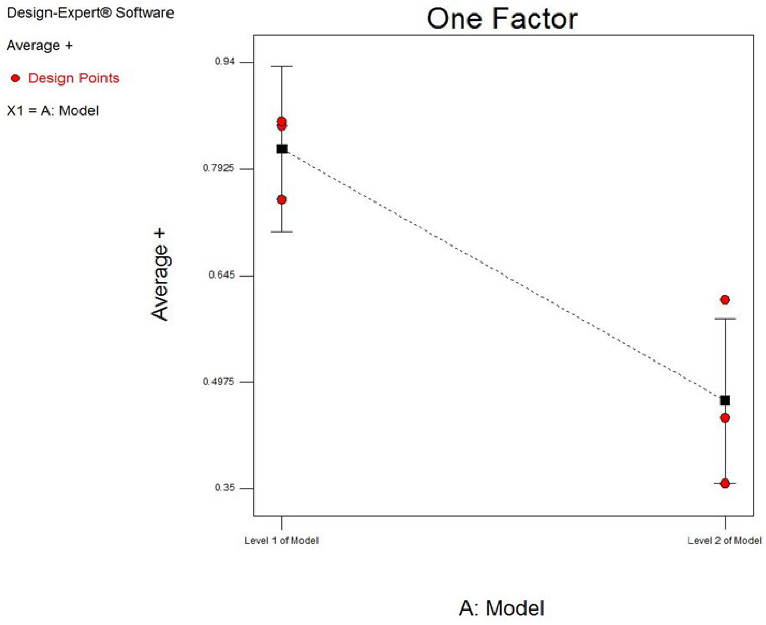
| Source | Sum of Squares | df | Mean Square | F Value | p-Value Prob > F | - |
|---|---|---|---|---|---|---|
| Model | 0.18 | 1 | 0.18 | 17.95 | 0.0133 | significant |
| A-Model | 0.18 | 1 | 0.18 | 17.95 | 0.0133 | - |
| Pure Error | 0.040 | 4 | 0.010 | - | - | - |
| Cor Total | 0.22 | 5 | - | - | - | - |
| Trial | Max + (mm) | Max − (mm) | Average + (mm) | Average − (mm) | ±1 mm (%) |
|---|---|---|---|---|---|
| D2 | 4.11 | −6.26 | 1.11 | −1.7 | 47.3 |
| D2A* | 3.28 | −4.05 | 0.991 | −0.846 | 59.3 |
| D2A* vs D2 | −20.2% | −35.3% | −10.7% | −50.2% | +25.4% |
© 2019 by the authors. Licensee MDPI, Basel, Switzerland. This article is an open access article distributed under the terms and conditions of the Creative Commons Attribution (CC BY) license (http://creativecommons.org/licenses/by/4.0/).
Share and Cite
Ortiz, M.; Penalva, M.; Iriondo, E.; López de Lacalle, L.N. Accuracy and Surface Quality Improvements in the Manufacturing of Ti-6Al-4V Parts Using Hot Single Point Incremental Forming. Metals 2019, 9, 697. https://doi.org/10.3390/met9060697
Ortiz M, Penalva M, Iriondo E, López de Lacalle LN. Accuracy and Surface Quality Improvements in the Manufacturing of Ti-6Al-4V Parts Using Hot Single Point Incremental Forming. Metals. 2019; 9(6):697. https://doi.org/10.3390/met9060697
Chicago/Turabian StyleOrtiz, Mikel, Mariluz Penalva, Edurne Iriondo, and Luis Norberto López de Lacalle. 2019. "Accuracy and Surface Quality Improvements in the Manufacturing of Ti-6Al-4V Parts Using Hot Single Point Incremental Forming" Metals 9, no. 6: 697. https://doi.org/10.3390/met9060697
APA StyleOrtiz, M., Penalva, M., Iriondo, E., & López de Lacalle, L. N. (2019). Accuracy and Surface Quality Improvements in the Manufacturing of Ti-6Al-4V Parts Using Hot Single Point Incremental Forming. Metals, 9(6), 697. https://doi.org/10.3390/met9060697