Article

A Study on Microstructure and Mechanical Properties of Micro Friction Stir Welded Ultra-Thin Al-1060 Sheets by the Shoulderless Tool

1
State Key Laboratory of Advanced Processing and Recycling of Non-ferrous Metal, Lanzhou University of Technology, Lanzhou 730050, China
2
School of Material Science and Engineering, Lanzhou University of Technology, Lanzhou 730050, China
*
Author to whom correspondence should be addressed.
Metals 2019, 9(5), 507; https://doi.org/10.3390/met9050507
Submission received: 8 April 2019 / Revised: 27 April 2019 / Accepted: 28 April 2019 / Published: 30 April 2019

Abstract

:
The welding tool is the key of micro friction stir welding (μFSW), which affects the heat input and the plastic forming of weld metal. In this paper, 0.8-mm-thick ultra-thin 1060-H24 aluminum sheets μFSW butt joints were used to compare and analyze the influence of the conventional tool and shoulderless tool on weld shaping, microstructure and mechanical properties. Besides, by measuring the axial force, transverse force and weld temperature in μFSW process, the influence of these two different tools on the heat input and metal flow mechanism of the weld were analyzed. The results show that the weld generated by the shoulderless tool has narrower width, less heat input and metal involved in plastic forming resulting in smaller HAZ (heat affected zone). The hardness of NZ (nugget zone) is obviously increased compared with that of the base metal. The highest tensile strength can reach 108.6 MPa, accounting for 78.6% of the base metal and 117.3% of the joint by the conventional tool. But the welding defects have to be overcome for industrial application of the shoulderless tool.

1. Introduction

Friction stir welding (FSW) is an advanced solid-state joining technique invented by The Welding Institute (TWI) in 1991, with advantages of no dust, no splash, no wire filling, high joint quality, small deformation, etc. [1,2,3,4,5]. With the development of this technology and the growing need in industry, the research on FSW technology is further developed in the direction of high-speed friction stir welding and ultra-thin precision welding [6]. The butt welding of ultra-thin sheets is wildly used in the field of precision manufacturing such as aviation, aerospace, microelectronics, etc. Therefore, micro friction stir welding (μFSW), as a breakthrough technology in precision manufacturing, has broad application prospects.
In 2004, Nishihara and Nagasaka proposed friction stir welding for thin-plate structural materials less than 1 mm, and named it as micro friction stir welding (μFSW) [7]. Because of the limited heat and load carried by the sheet, TWI is exploring a low temperature and load μFSW solution. Nee Joo Teh et al. conducted a detailed study on the balanced input of welding force and heat in μFSW process and successfully obtained butt and lap joints with excellent weld formation by using the welding fixture and conical welding tool they developed [8]. In this way, the weld is good for sealed packaging of aluminum alloy, copper alloy and thermoplastic materials. For ultra-thin plate friction stir welding, the rotation speed is more than ten times higher than that of conventional friction stir welding [9]. The high rotation speed can increase the heat input and generates low axial force [10]. Therefore, welded joints with excellent mechanical properties can be more easily obtained. Cerri et al. studied properties of the joint at different temperatures, using 0.8-mm-thick 6082-T6 sheets as base metal, and found that the flow stress decreased with the increasing of temperature [11]. Based on the experiments, Elangovan et al. noted that different rotation speeds lead to different heat input and plastic metal flow in metal forming, finally influence the mechanical properties of the joint [12].
The tool producing high-density heat input is more suitable for ultra-thin sheets μFSW [13,14]. Lammlein et al. successfully conducted closed profile welding on 3.2-mm-thick aluminum sheets by using a shoulderless tool and studied the microstructure and plastic fluidity of the weld metal [15]. However, for now, there have been insufficient studies on the influence mechanism of microstructure and mechanical properties of the ultra-thin aluminum sheets welded by the shoulderless tool. In μFSW process with the shoulderless tool, less heat input and base metal is involved in the plastic flow [16,17]. Thus, the energy is saved in this process. Besides, no tilt angle is needed, which can reduce the difficulty of equipment control.
To further explore how welding parameters affect the microstructure and mechanical properties of the joint, it is extremely necessary to measure the force and temperature variations experienced by the test sheets under different welding parameters during the welding process. Papahn et al. designed and developed a novel fixture for simultaneously measuring axial and transverse forces during friction stir welding process [18]. There are still many researchers who have carried out this measurement work, making significant contributions to understanding the impact of process parameters on the microstructure and mechanical properties of the joint [19,20,21,22,23,24,25,26,27].
This paper explored the shoulderless tool’s influence on μFSW process of ultra-thin 1060-H24 aluminum sheets in contrast with that of the conventional tool. The influence mechanism of weld surface appearance, microstructure and mechanical properties of μFSW joints are discussed, in order to provide some reference information for the application of shoulderless μFSW.

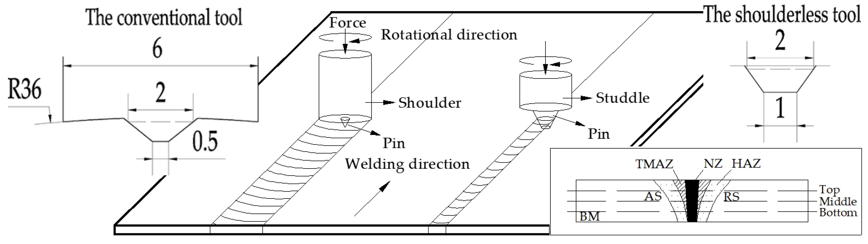
2. Materials and Methods

In the experiment, 0.8-mm-thick 1060-H24 aluminum sheets (150 mm × 25 mm × 0.8 mm) were used for μFSW butt joints. Its chemical composition is listed in Table 1.
Two different types of the welding tool are shown in Figure 1. The tool was made of WC-Co cemented carbide. The conventional tool is composed of a shoulder diameter of 6 mm and a conical pin. The pin was tapered from 2 mm at root diameter to 0.5 mm at tip diameter with a length of 0.6 mm. The shoulderless tool is only a conical pin with a 2-mm root diameter, 1-mm tip diameter and 0.8-mm pin length. A fixed end was used to stabilize the tool pin, but just the pin actually participated in the friction and stir effect of μFSW process. The welding process was performed with the different welding tools, and the used welding parameters are listed in Table 2. Under each set of welding parameters, welding tests were performed with one kind of the tools for three times. The conventional tool was applied to the sheets under a 2° tilt angle, but no tilt angle was set in μFSW process by the shoulderless tool.
Test sheets were cleaned with acetone to remove the oil and oxide on the surface before welding, and then were fixed on the self-made fixture showed in Figure 2. The fixture is also a force and temperature measuring device which is used for studying the force and temperature distribution of the sheets during μFSW process. For this, K-Type thermocouples were used and the probes on the root side of the weld were fixed on the backing plate surface through with high temperature glue. AS shown in Figure 3, points 1–4 were the probe location and the weld length not included the radius of tools was 30 mm. Points 2–4 were on the root side of the weld center and point 1 beside point 2 was used to measure the ambient temperature of the weld. To reduce the heat loss, a titanium alloy with lower thermal conductivity was selected as the backing plate. The axial force was measured by three load cells fixed under the backing plate, meanwhile, the transverse force was measured by one load cell fixed on a wall perpendicular to the welding direction. NI (National Instruments Corporation, Austin, TX, USA) USB-6008 data acquisition card and LabVIEW 13.0 Development System (National Instruments Corporation, Austin, TX, USA) were used to record the welding force and temperature data at a sampling rate of 1000 Hz. The collected data was 500 pts Savitzky–Golay smoothed in order to make the variation trend of the curve clearer. Then the impact of the different tools on the welding force and temperature of μFSW process were analyzed and contrasted.
Specimens for metallographic and mechanical properties tests were machined from the welded sheets normal to the welding direction. Three samples for mechanical properties tests were taken from each welded test sheets. After being ground by metallographic sandpapers and mechanically polished, the samples were wiped with Keller reagent (2.5 mL HNO3, 1.5 mL HCl, 1 mL HF, and 95 mL H2O). The grain size and microstructural features of the welded joint have been observed by light microscopy Axio Scope A1 (Zeiss Corporation, Oberkochen, Baden-Württemberg, Germany), and the tensile fracture morphology by a Quanta FEG450 SEM (FEI Corporation, Hillsboro, OR, USA). Tensile strength tests of the joint were carried out at a tensile rate of 0.5 mm/min by using an Instron 3382 universal testing machine (Instron Corporation, Norwood, MA, USA). The Vickers microhardness was measured with a microhardness tester along the middle line of transverse cross section with the load of 1.96 N for 10 s at each point. The measuring position of the microhardness is shown in Figure 1, it should be ensured that both the top, middle and bottom layers come across the nugget zone (NZ), thermal-mechanical affected zone (TMAZ), heat affect zone (HAZ) and base metal (BM), including the advancing side (AS) and retreating side (RS) of the joint. The top layer was 0.2 mm from the top surface, and the bottom layer was 0.2 mm from the bottom surface. Each point was 0.2 mm away from another one.

3. Results and Discussion

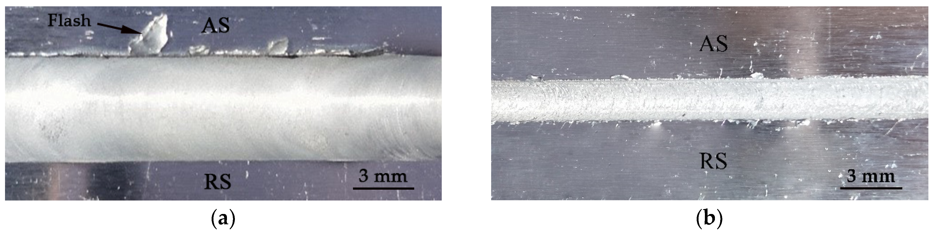
3.1. Weld Surface Appearance

The surface appearance of welds by the different tool is shown in Figure 4. It can be seen that both two welds have good surface appearance without any defects such as grooves and cracks. The surface appearance of welds by the conventional tool is smooth and delicate, but the weld is wide and the thickness of sheets are cut down badly, flash defects also exists. Compared with the conventional tool, the width of welds by shoulderless tool is narrower, because the stir zone is narrowed due to the small diameter of the tool pin. Though heat input generated by the shoulderless tool is lower, but base metal can also come to the plastic flow state of 1060-H24 aluminum because of the high-speed rotation of the shoulderless tool. There is granular burr but no other defect on the weld surface. And the weld has a low thickness reduction rate.

3.2. Welding Force

The weld length was 30 mm. The rotation speed of the tool was set at 11,000 rpm and the welding speed was 140 mm/min, with which weld shaped good. The dwell time at start of the weld was 5 s after the plunge depth reached 0.06 mm when used the conventional tool, and then start the transverse feeding process of μFSW. When used the shoulderless tool, the plunge depth should reach 0.7 mm and the dwell time at start of the weld was 5 s either.
As shown in Figure 5, axial forces in welding process at the rotation speed of 11,000 rpm were analyzed. According to the movement of the tool, the μFSW process could be divided into three stages, namely, the plunging stage, the dwelling stage and the stable welding stage.
In the plunging stage, the spindle feed rate was set to a small value, in order to analyze the change of the axial force in detail. In this stage, axial forces generated by the conventional tool on the welded sheet increased rapidly with slow plunging of the tool pin. At the moment when the shoulder touched the sheet surface (I), the axial force reached the maximum value of 147 N. Meanwhile, a large amount of heat was generated due to the friction effect between high-speed rotating shoulder and the sheet surface. Therefore, the metal in the friction contact area softened and achieved the plasticizing state. The axial force began to decrease in this softening process. Since the plunging of the tool was not finished, the metal which had not been in contact with the tool yet in the vertical direction to the sheet surface was heated in different extent, but it did not achieve the plasticizing state. Also, it had reaction force on the tool. Therefore, the axial force was slowly decreased. When the plunge depth of the shoulder reached 0.1 mm, plunging stage of the tool was finished. In the dwelling stage, under the sufficient friction and stir effect of the tool, most of base metal below the tool softened and achieved the plasticizing state (II). Thus, the axial force rapidly reduced to a lower level due to the disappearance of the reaction force. In the initial welding stage, the axial force maintained at about 50 N for 2 s and then began to drop to a lower level rapidly when the base metal softened seriously (III). Then in the stable welding stage, it maintained at this level (about 28 N) until the end of the test sheet was welded. Finally, when the tool rose and left the sheet surface, the whole welding process finished and the axial force deceased sharply toward 0 N.
When the shoulderless tool was used in μFSW process, in the plunging stage, the axial force increased rapidly until the plunge depth of the tool pin reached 0.7 mm. Then, the axial force decreased dramatically, but it did not have the slow decline (from I to II) and the secondary descent (from III to IV) because of the small pin diameter of the shoulderless tool. In the stable welding stage, the axial force fluctuated on the basis of 40 N. When the welding stage finished, there was also 2 s for the tool dwelling which was included in the exiting stage, and then the tool began to leave the test sheets. When the conventional tool was used, the base metal received the heat generated by the friction effect of the shoulder in this 2 s and rapidly softened. This situation did not happen to the shoulderless tool. So, the process (until forces were 0 again) with the shoulderless tool was about 2 s longer than that with the conventional tool in Figure 5.
The transverse force generated by two types of welding tools in μFSW process are shown in Figure 6. Frictional forces on the AS and RS were opposite during the rotation of the tool. Thus, transverse forces were above or below 0, when the pre-tightening force was loaded. However, under the rotation speed of 11,000 rpm, transverse forces of the conventional tool remained positive in the stable welding stage (Figure 6a), while transverse forces of the shoulderless tool were above or below 0 (Figure 6b). It should be that the small diameter and high rotation speed of the shoulderless tool brought extremely small thrust to the test sheet, which could not be identified by the load cell. And there were some high frequency wave periods of the transverse force in μFSW process caused by vibration of the fixture.

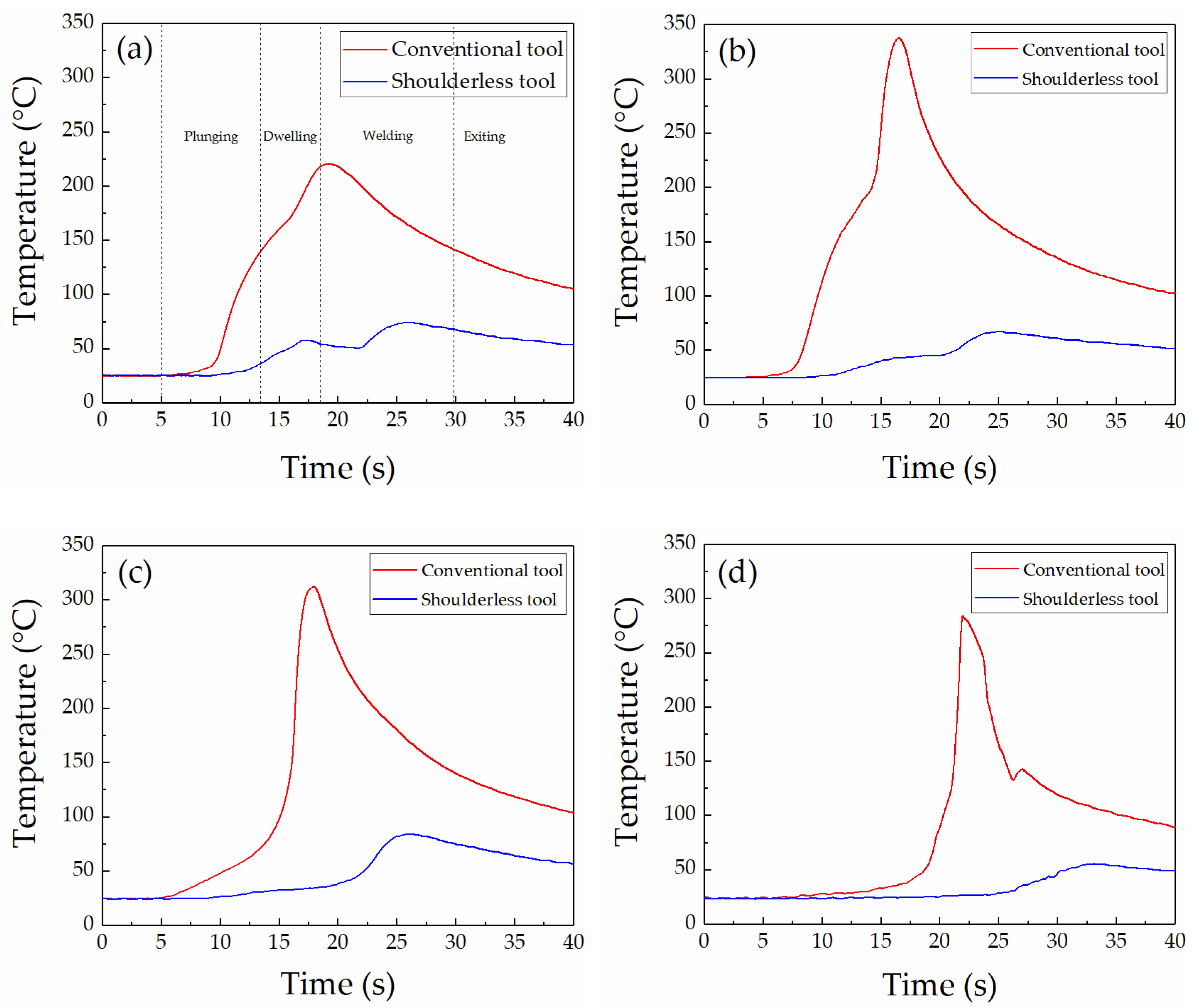
3.3. Weld Temperature

The heat input during μFSW process with the conventional tool can be expressed by the Equation (1) [28].
Q F = 2 3 π τ c o n t a c t ω ( R s h o u l d e r 3 + 3 R p r o b e 2 H p r o b e )
where QF is the heat input, τ is the material yield stress at some welding temperature, ω is the angular velocity of welding tool, Rshoulder is the radius of conventional shoulder, Rprobe is the radius of tool pin, and Hprobe is the height of tool pin.
When use the shoulderless tool, only the tool pin works, so the heat input can be expressed by the Equation (2).
Q F = 2 3 π τ c o n t a c t ω ( 3 R p r o b e 2 H p r o b e )
It can be seen from the Equation (1) that the heat input of μFSW process grows with the increase of the shoulder diameter when the other parameters are unchanged. In this paper, the heat input of μFSW process with the shoulderless tool is 7.3% of that with the conventional tool according to the Equation (2), since it is only affected by the pin.
In order to verify the huge difference of heat input generated by the different tools, the dynamic temperature curves of points 1–4 shown in Figure 3 at 11,000 rpm rotation speed and 140 mm/min welding speed are shown in Figure 7. When the conventional tool is used in μFSW process, the weld temperature rises more quickly compared with the shoulderless tool. The weld temperature of the conventional tool during μFSW process can reach up to 337 °C, which is enough to make the base metal come to the plasticizing state. In Figure 7a,b, the weld temperature curve of the shoulderless tool is found to be concave between 20–25 s, which may be caused by the vibration of the fixture during μFSW process. The thermocouple probe of point 1 and 2 temporarily left its original position with the vibration of the backing plate in the fixture and caused the measured temperature to drop. The highest weld temperature of the shoulderless tool is 84 °C. This value is lower than the true temperature of the weld because there is heat-transfer medium (high temperature glue) between the weld and thermocouple probe causing heat loss. The same happens to the conventional tool. The temperature at point 1 is much lower than that of points 2–4, because the point 2–4 were on the root side of the weld center and the point 1 beside the point 2 was used to measure the ambient temperature of the weld.

3.4. Macro Morphology and Microhardness

Figure 8 indicates the cross-sectional macroscopic morphology of the two μFSW joints after being etched by Keller reagent. The welded joint is divided into BM, HAZ, TMAZ and NZ. The grain size of NZ is smaller than that of other areas because of stir action of the tool. Also, clear boundary between TMAZ and NZ can be seen. Moreover, as shown in Figure 8a, μFSW joints by the conventional tool (the diameter of NZ is 3.2 mm) have large HAZ and severe thickness reduction. While, as shown in Figure 8b, joints by the shoulderless tool (the diameter of NZ is 0.8 mm) have small HAZ, less plastic metal involved in μFSW process, narrow weld width, and low thickness reduction rate, since it only influenced by the tool pin. According to the limited heat input generated by the shoulderless tool, a small amount of base material around the tool pin was extruded to weld edges in the welding process because of the cutting action of the pin and the deficiency of material recovery could be achieved by the shoulder, resulting in a more mild thickness reduction compared with that of the conventional tool.
In the μFSW process, HAZ of the joint is only subjected to the thermal cycling effect but no mechanical action of the welding tool. So, the distortion energy in HAZ is low, and the microstructure is composed of coarse grains. TMAZ is subjected to the stir and heat double effects, resulting in the deformation of the microstructure. The grain in this area is elongated. NZ is mainly subjected to the stir effect of the tool pin. The material in this area has good fluidity in the welding process and the microstructure is composed of fine equiaxed grains.
When the conventional tool is used, the metal is mechanically affected by the shoulder. The heat is easily transmitted to the bottom of the weld. The base metal covered by the entire shoulder is at a higher temperature in the welding process [29]. TMAZ of the joint is larger, and the grain in this area is stretched. Compared with the conventional tool, the metal is only affected by the tool pin when the shoulderless tool is used, and the influence range of the tool is smaller. A lower heat input is generated by the dual function of high-speed rotation and stir effect of the tool pin, and a smaller amount of base metal undergoes the rapid temperature rising and crystallization process. The plastic metal flow has an amply fluxion and the microstructure is homogeneous. Besides, the bonding zone between HAZ and TMAZ of the joint is smaller and inconspicuous.
Figure 9 shows the average microhardness distribution curve of the weld cross section. The measuring points are distributed in the top, middle and bottom layer shown in Figure 1. Because microhardness of a zone is closely related to the microstructure the zone has, the top layer of the weld has a higher dynamic recovery and recrystallization degree than that of the bottom layer because of the stir effect of the tool. So, in this layer, the phenomenon of grain refining is the most obvious and the microhardness is the highest. The bottom layer is strongly stirred under mechanical actions of the tool pin. Since the less heat generated by the pin with small diameter and the heat dissipation caused by the backing plate, the weld has a low-grade process of dynamic recovery and recrystallization.
Grains in the HAZ on the AS experience a rapid growth, where the hardness is the lowest. Because the direction of the force loaded on the AS by the tool is different from that on the RS, the dispersion strengthening phase is collected in the RS, resulting in a more serious tendency of hardening on the AS. Therefore, the mechanical properties of HAZ on the AS is poor. It can be seen from Figure 9 that the microhardness curve of the butt joint by the conventional tool shows ‘W’ type, which is similar to the microhardness distribution of other aluminum alloy μFSW joints [30,31]. The microhardness of the weld is lower than that of the base metal, and the lowest hardness zone appears in the bonding zone between TMAZ and HAZ. Due to the high local temperature of the test sheets during the welding process with the conventional tool, the annealing of the material occurs, the grain begins to coarsen, and shows in macroscopic view that the mechanical properties of the material are lowered. For the weld by the shoulderless tool, the microhardness of NZ is obviously increased compared with that of the base metal. Due to the low temperature shown in Figure 7 and strain hardening effect on the test sheets, the dislocation energy around the processed area is increased, resulting in a hardness increase. Microstructure in TMAZ of the joint is affected by the mechanical stir and heat input effects, and HAZ is only affected by the heat input, so the hardness of the four zones is as following: NZ > TMAZ > BM > HAZ.

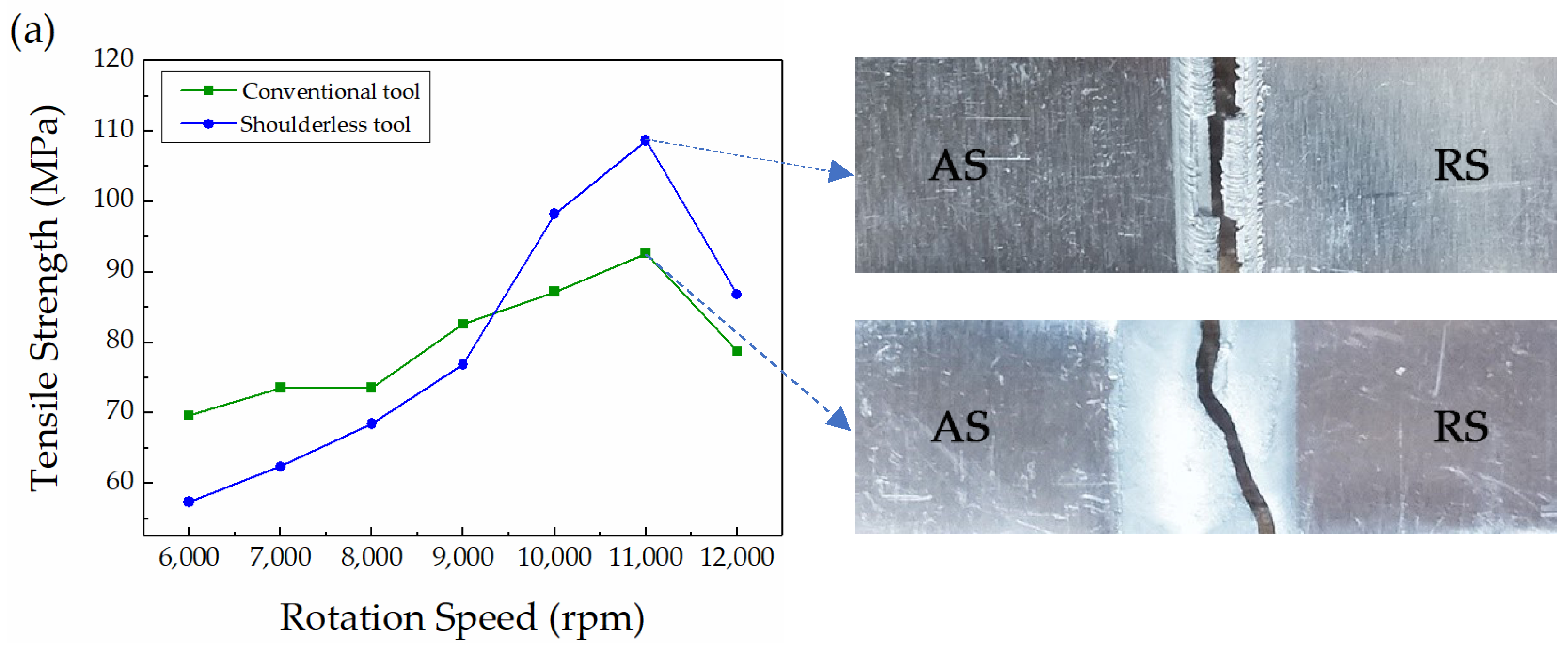
3.5. Tensile Properties of the Joint

The actual tensile strength of the base metal measured in the tensile test was 138.2 MPa. Figure 10a shows the average tensile strength of μFSW joints by the different tool at different rotation speeds. When the rotation speed was 11,000 rpm and the welding speed was 140 mm/min, the tensile strength of the joint by the conventional tool reached the best value of 92.6 MPa, which was 67.0% of that the base metal had. The best case of tensile properties was fractured in NZ, along the welding direction extended to HAZ on the RS. Under the same parameters, the cracks initiated at the bottom of the joint and propagated along the boundary between TMAZ and NZ on the RS, but part of the joint was fractured in the upper layer of TMAZ on the AS. The highest tensile strength was 108.6 MPa, accounting for 78.6% of the base metal and 117.3% of the joint by the conventional tool. Figure 10a reflects two important regular features of the strength variation at different rotation speeds. Firstly, when the welding speed is fixed, whether the conventional or the shoulderless tool is used, the tensile strength increases first and then decreases with the growth of rotation speed. Secondly, when the rotation speed is less than 10,000 rpm, the tensile strength of the joint by the conventional tool is higher than that of the joint by the shoulderless tool. This should be that there is insufficient heat input when the rotation speed of the shoulderless tool is less than 10,000 rpm, resulting in a poor metal fluidity in the weld and weak connection between two test sheets.
As shown in Figure 10b, when the rotation speed is fixed, whether the conventional tool or the shoulderless tool is used, the tensile strength increases first and then decreases with the growth of the welding speed. In addition, no matter how the rotation speed changes among 80–200 mm/min, the tensile strength of the joint by the shoulderless tool is higher than that of the joint by the conventional tool but lower than that of the base metal either, which has a certain relationship with the heat input during μFSW process and defects possibly appear in the welded joint. So, the fracture surface analysis must be done. Without the optimum welding parameters, the joint by the conventional tool was fractured in NZ when the rotation speed was 11,000 rpm and the welding speed was 160 mm/min. Under the same parameters, the joint by the shoulderless tool was fractured along the boundary between TMAZ and NZ on the RS.

3.6. Morphology of The Tensile Fracture Surface

The tensile fracture surface of the sheets welded by the different welding tools are shown in Figure 11. For the joint by the conventional tool, the fracture surface morphology presented at low magnification power is shown in Figure 11a. The characteristics of the upper and lower layer of fractures are significantly different. The region A (the upper layer) and B (the lower layer) in Figure 11a presented at high magnification are shown in Figure 11b,c respectively. The deformation degree of region A is very low. Many large and deep dimples with tearing edges associated with micropores appear on the fracture surface of region A. The joint comes to be ineffective before the dimple is completely opened. Besides, as shown in Figure 11c, the dimple in region B is homogeneously distributed in this area and has a high degree of deformation, indicating the typical ductile fracture.
For the joint welded by the shoulderless tool, the fracture surface morphology presented at low magnification is shown in Figure 11d, region C and D in Figure 11d presented at high magnification are shown in Figure 11e,f respectively. Layered fracture also occurs after the tensile test of the joint by the shoulderless tool. As shown in Figure 11f, the fractures of region D change from dimple to ductile slip-band fracture because of the welding defect above the bottom layer of the joint as a result of the heat input and the axial force, which easily becomes the initiation of crack. The upper layer is strongly stirred by the pin, which resulting in grain refinement in this area. While, because of heat loss of the ultra-thin sheet, insufficient material flow is easy to take place. Moreover, because forces brought by the pin are different between the upper and lower layer in the welding process, the mechanical properties of the upper and lower layers are different either, resulting in a stratification phenomenon. Therefore, the fracture occurs in the combination zone between these two layers.

4. Conclusions

The main results of this investigation are:
  • Compared with the conventional tool, μFSW process with the shoulderless tool has advantages of low heat input, simple process as well as excellent mechanical properties. Thus, it has bright prospects for industrial application.
  • The μFSW process of 0.8-mm-thick ultra-thin 1060-H24 aluminum sheets with the shoulderless tool is achieved in this thesis. The joint by the shoulderless tool has small heat input and HAZ because it is only influenced by the tool pin. Among the four zones, the microhardness is as following: NZ > TMAZ > BM > HAZ.
  • The μFSW joint of 0.8-mm-thick ultra-thin 1060-H24 aluminum sheets by the shoulderless tool has the best mechanical properties with the welding speed of 140 mm/min and the rotation speed of 11,000 rpm. The highest tensile strength of the joint by the shoulderless tool can reach 108.6 MPa, accounting for 78.6% of the base metal and 117.3% of the joint by the conventional tool. Also, the fracture mode of the joint is ductile fracture. The welding defects have to be overcome for industrial application of the shoulderless tool.

Author Contributions

Funding acquisition, data curation and writing—original draft preparation, C.Z.; conceptualization, methodology and visualization, W.W.; writing—review & editing and formal analysis, C.Z. and X.J.; resources and investigation, C.R. and Z.Q.

Funding

This research was funded by School Technology Fund of State Key Laboratory of Advanced Processing and Recycling of Non-ferrous Metal in Lanzhou University of Technology.

Acknowledgments

The authors would like to thank the support of the laboratories and the help of Mao Yuanning for writing the draft.

Conflicts of Interest

The authors declare no conflicts of interest.

References

  1. Dawes, C.J. An introduction to friction stir welding and its development. Weld. Met. Fabr. 1995, 63, 279–285. [Google Scholar]
  2. Mishra, R.S.; De, P.S.; Kumar, N. Friction Stir Welding and Processing; Springer: Cham, Switzerland, 2010; pp. 13–58. [Google Scholar] [CrossRef]
  3. Thomas, W.M.; Nicholas, E.D. Friction stir welding for the transportation industries. Mater. Des. 1997, 18, 269–273. [Google Scholar] [CrossRef]
  4. Joelj, D. The friction stir welding advantage. Weld. J. 2001, 80, 30–34. [Google Scholar]
  5. Nandan, R.; Debroy, T.; Bhadeshia, H.K.D.H. Recent advances in friction-stir welding – Process, weldment structure and properties. Prog. Mater. Sci. 2008, 53, 980–1023. [Google Scholar] [CrossRef] [Green Version]
  6. Padhy, G.K.; Wu, C.S.; Gao, S. Friction stir based welding and processing technologies-processes, parameters, microstructures and applications: A review. Mater. Sci. Technol. 2017, 34, 1–38. [Google Scholar] [CrossRef]
  7. Nishibara, T.; Nagasaka, Y. Development of Micro-Friction Stir Welding. In Proceedings of the 5th International Friction Stir Welding Symposium, Metz, France, 14–16 September 2004. [Google Scholar]
  8. Developments in Micro Applications of Friction Stir Welding. Available online: https://www.twi-global.com/technical-knowledge/published-papers/developments-in-micro-applications-of-friction-stir-welding (accessed on 5 December 2018).
  9. Scialpi, A.; De Giorgi, M.; De Filippis, L.A.C.; Nobile, R.; Panella, F.W. Mechanical analysis of ultra-thin friction stir welding joined sheets with dissimilar and similar materials. Mater. Des. 2008, 29, 928–936. [Google Scholar] [CrossRef]
  10. Chen, S.; Zhou, Y.; Xue, J.; Ni, R.; Guo, Y.; Dong, J. High Rotation Speed Friction Stir Welding for 2014 Aluminum Alloy Thin Sheets. J. Mater. Eng. Perform. 2017, 26, 1337–1345. [Google Scholar] [CrossRef]
  11. Cerri, E.; Xiang, W.; Embury, J.D. Mechanical Properties and Microstructural Evolution of Friction-Stir-Welded Thin Sheet Aluminum Alloys. Metall. Mater. Trans. A 2011, 42, 1283–1295. [Google Scholar] [CrossRef]
  12. Elangovan, K.; Balasubramanian, V.; Valliappan, M. Effect of Tool Pin Profile and Tool Rotational Speed on Mechanical Properties of Friction Stir Welded AA6061 Aluminium Alloy. Adv. Manuf. Process. 2008, 23, 251–260. [Google Scholar] [CrossRef]
  13. Biswas, P. Effect of tool pin profile on the material flow characteristics of AA6061. J. Manuf. Process. 2017, 26, 382–392. [Google Scholar] [CrossRef]
  14. Rodrigues, D.M.; Loureiro, A.; Leitao, C.; Leal, R.M.; Chaparro, B.M.; Vilaça, P. Influence of friction stir welding parameters on the microstructural and mechanical properties of AA 6016-T4 thin welds. Mater. Des. 2009, 30, 1913–1921. [Google Scholar] [CrossRef]
  15. Lammlein, D.H.; Delapp, D.R.; Fleming, P.A.; Strauss, A.M.; Cook, G.E. The application of shoulderless conical tools in friction stir welding: An experimental and theoretical study. Mater. Des. 2009, 30, 4012–4022. [Google Scholar] [CrossRef]
  16. Galvão, I.; Leal, R.M.; Rodrigues, D.M.; Loureiro, A. Influence of tool shoulder geometry on properties of friction stir welds in thin copper sheets. J. Mater. Process. Technol. 2013, 213, 129–135. [Google Scholar] [CrossRef] [Green Version]
  17. Zhang, Z.; Liu, H. Effect of pin shapes on material deformation and temperature field in friction stir welding. Trans. China Weld. Inst. 2011, 32, 5–8. [Google Scholar] [CrossRef]
  18. Papahn, H.; Haghpanahi, M.; Bahemmat, P. Using a novel fixture to study of temperature and applied forces during friction stir welding. J. Braz. Soc. Mech. Sci. Eng. 2015, 39, 531–541. [Google Scholar] [CrossRef]
  19. Amini, S.; Amiri, M.R. Pin axis effects on forces in friction stir welding process. Int. J. Adv. Manuf. Technol. 2015, 78, 1795–1801. [Google Scholar] [CrossRef]
  20. Paoletti, A.; Lambiase, F.; Di Ilio, A. Analysis of forces and temperatures in friction spot stir welding of thermoplastic polymers. Int. J. Adv. Manuf. Technol. 2015, 83, 1395–1407. [Google Scholar] [CrossRef]
  21. Zhao, S.; Bi, Q.; Wang, Y. An axial force controller with delay compensation for the friction stir welding process. Int. J. Adv. Manuf. Technol. 2015, 85, 2623–2638. [Google Scholar] [CrossRef]
  22. Kim, K.-H.; Bang, H.-S.; Ro, C.-S.; Bang, H.-S. Influence of preheating source on mechanical properties and welding residual stress characteristics in ultra thin ferritic stainless steel hybrid friction stir welded joints. Int. J. Precis. Eng. Manuf. Green Technol. 2017, 4, 393–400. [Google Scholar] [CrossRef]
  23. Jain, R.; Pal, S.K.; Singh, S.B. A study on the variation of forces and temperature in a friction stir welding process: A finite element approach. J. Manuf. Process. 2016, 23, 278–286. [Google Scholar] [CrossRef]
  24. Shukla, A.K.; Chelladurai, H.; Tiwari, S. Effect of Pre-Heat Time on Force During Friction Stir Welding of Aluminium 1050 Alloy. Mater. Today Proc. 2017, 4, 3618–3626. [Google Scholar] [CrossRef]
  25. Das, B.; Pal, S.; Bag, S. Design and development of force and torque measurement setup for real time monitoring of friction stir welding process. Measurement 2017, 103, 186–198. [Google Scholar] [CrossRef]
  26. Forcellese, A.; Simoncini, M.; Casalino, G. Influence of Process Parameters on the Vertical Forces Generated during Friction Stir Welding of AA6082-T6 and on the Mechanical Properties of the Joints. Metals 2017, 7, 350. [Google Scholar] [CrossRef]
  27. Zhao, Y.; Wu, A.P.; Ren, J.L.; Sato, Y.S.; Kokawa, H.; Miyake, M.; Yan, D.Y. Temperature and force response characteristics of friction stir welding on Invar 36 alloy. Sci. Technol. Weld. Join. 2013, 18, 232–238. [Google Scholar] [CrossRef]
  28. Schmidt, H.; Hattel, J.; Wert, J. An analytical model for the heat generation in friction stir welding. Model. Simul. Mater. Sci. Eng. 2004, 12, 143. [Google Scholar] [CrossRef]
  29. Huang, Y.; Meng, X.; Zhang, Y.; Cao, J.; Feng, J. Micro friction stir welding of ultra-thin Al-6061 sheets. J. Mater. Process. Technol. 2017, 250, 313–319. [Google Scholar] [CrossRef]
  30. Liu, F.; Li, F.U.; Zhang, W.; Meng, Q.; Dong, C.; Luan, G. Interface structure and mechanical properties of friction stir welding joint of 2099-T83/2060-T8 dis-similar Al-Li alloys. Acta Metall. Sin. 2015, 51, 281–288. [Google Scholar] [CrossRef]
  31. Zhou, Y.; Chen, S.; Wang, J.; Wang, P.; Xia, J. Influences of pin shape on a high rotation speed friction stir welding joint of a 6061-t6 aluminum alloy sheet. Metals 2018, 8, 987. [Google Scholar] [CrossRef]
Figure 1. Schematic of μFSW (micro friction stir welding) process by conventional tool and shoulderless tool. (BM-base metal, AS-advancing side of the weld, RS-retreating side of the weld, TMAZ-thermo-mechanically affected zone, NZ-nugget zone, HAZ-heat affected zone).
Metals 09 00507 g001
Figure 2. The fixture for ultra-thin sheets welding.
Metals 09 00507 g002
Figure 3. Schematic of the temperature measuring position.
Metals 09 00507 g003
Figure 4. The surface appearance of the weld: (a) the conventional tool; (b) the shoulderless tool.
Metals 09 00507 g004
Figure 5. Axial force generated by the different tool (11,000 r/min, 140 mm/min, 500 pts Savitzky–Golay smoothed).
Metals 09 00507 g005
Figure 6. Transverse force generated by the different tool (11,000 r/min, 140 mm/min, 500 pts Savitzky–Golay smoothed): (a) the conventional tool; (b) the shoulderless tool.
Metals 09 00507 g006
Figure 7. Weld temperature generated by the different tool (11,000 r/min, 140 mm/min): (a) dynamic temperature of the point 1; (b) dynamic temperature of the point 2; (c) dynamic temperature of the point 3; (d) dynamic temperature of point 4.
Metals 09 00507 g007
Figure 8. Macro-morphology of the weld: (a) the conventional tool; (b) the shoulderless tool.
Metals 09 00507 g008
Figure 9. Hardness distribution characteristics of cross-section (11,000 r/min, 140 mm/min): (a) the conventional tool; (b) the shoulderless tool.
Metals 09 00507 g009
Figure 10. Tensile strength and fracture modes by the different tool: (a) at different rotation speed; (b) at different welding speed. (AS-advancing side of the weld, RS-retreating side of the weld)
Metals 09 00507 g010aMetals 09 00507 g010b
Figure 11. Fracture surface morphologies of the joints by the conventional tool (a) and the shoulderless tool (d): (b) Region A presented at high magnification; (c) Region B presented at high magnification; (e) Region C presented at high magnification; (f) Region D presented at high magnification.
Metals 09 00507 g011
Table 1. Chemical composition of 1060-H24 aluminum (mass fraction/%).
SiFeCuMgMnZnTiVAl
0.150.200.050.030.030.050.030.03margin
Table 2. Welding parameters.
Used ToolsRotation Speed
(rpm)
Welding Speed
(mm/min)
Plunging Rate
(mm/min)
Conventional tool6000–12,0001405
11,00080–200
Shoulderless tool6000–12,0001405
11,00080–200

