Review

Electromagnetic Forces in Continuous Casting of Steel Slabs

1
Department of Mechanical Engineering, Colorado School of Mines, 1610 Illinois Street, Golden, CO 80401, USA
2
Department of Mechanical Science and Engineering, University of Illinois at Urbana-Champaign, 1206 West Green Street, Urbana, IL 61801, USA
*
Author to whom correspondence should be addressed.
Metals 2019, 9(4), 471; https://doi.org/10.3390/met9040471
Submission received: 23 March 2019 / Revised: 14 April 2019 / Accepted: 20 April 2019 / Published: 23 April 2019
(This article belongs to the Special Issue Continuous Casting)

Abstract

:
This paper reviews the current state of the art in the application of electromagnetic forces to control fluid flow to improve quality in continuous casting of steel slabs. Many product defects are controlled by flow-related phenomena in the mold region, such as slag entrapment due to excessive surface velocity and level fluctuations, meniscus hook defects due to insufficient transport of flow and superheat to the meniscus region, and particle entrapment into the solidification front, which depends on transverse flow across the dendritic interface. Fluid flow also affects heat transfer, solidification, and solute transport, which greatly affect grain structure and internal quality of final steel products. Various electromagnetic systems can affect flow, including static magnetic fields and traveling fields which actively accelerate, slow down, or stir the flow in the mold or strand regions. Optimal electromagnetic effects to control flow depends greatly on the caster geometry and other operating conditions. Previous works on how to operate electromagnetic systems to reduce defects are discussed based on results from plant experiments, validated computational models, and lab scale model experiments.

1. Introduction

Continuous casting is the dominant process to manufacture steel, producing over 96% of steel in the world [1]. Thus, even small improvements to this process can have great impact. During solidification of molten steel, many complex phenomena arise, including multiphase fluid flow, particle transport and capture, heat transfer, solidification, and solute redistribution, which are strongly interrelated and can affect various surface and internal defects if process parameters are not controlled within optimal ranges for a given caster. In the mold region, where initial solidification occurs, fluid flow greatly affects steel surface quality, according to surface turbulence, flow instability, transport and capture of argon bubbles and inclusions, superheat transport, and meniscus solidification. In addition, steel internal quality depends greatly on heat transfer, solidification, and solute and dissolved gas transport, which affect segregation, porosity, and microstructure formation in the strand region of the process. These phenomena must be controlled within acceptable process windows to avoid defects and achieve ideal grain structure, and solute distribution.
Many efforts have been made to control fluid flow in the mold, which is responsible for many surface and internal defects in steel slab casting [2,3,4]. To control the mold flow pattern and reduce surface instability in the mold, the effects of nozzle geometry including port shape [5,6,7], size [5], angle [5,8,9,10], bottom design [5,11], and the flow control system [12] (stopper rod vs. slide gate) have been investigated. Other studies have investigated casting conditions including casting speed [13], argon gas injection [14,15,16], and nozzle submergence depth [17]. The effects of soft reduction on center segregation [18] and porosity [18,19] in the strand has been investigated to improve internal quality. Together with these process parameters, the application of electromagnetic (EM) forces is an attractive method to control phenomena related to fluid flow because the induced forces intrinsically adjust to molten steel flow variations, and field strength has the potential to be adjusted during operation. Thus, understanding and optimizing the effects of electromagnetic forces on the various continuous casting phenomena offer an important way to maintain quality and increase production for a given caster.
Tools to quantify the effects of electromagnetic forces on continuous casting phenomena include plant measurements, lab scale modeling with low melting temperature alloys, and computational modeling. In particular, computational models validated with plant data are a powerful methodology to understand the phenomena and to suggest practical strategies to optimize the operation of electromagnetic systems [20,21,22,23].
Various types of the electromagnetic systems have been developed and implemented into commercial slab casters to apply static and/or traveling magnetic fields to control fluid flow, particle transport and capture, heat transfer, and solidification during the continuous casting of steel slabs. Static magnetic fields have been widely applied as Electromagnetic Braking (EMBr) systems, including local, single-ruler, and double-ruler systems. These EMBr systems were invented to maintain a double-roll flow pattern [16] and to stabilize the fluid flow, especially at high casting speed. Local EMBr fields tend to slow down jet flow as it passes through a circular-shaped field region through the mold thickness [24], as shown in Figure 1a. Single-ruler EMBr (Figure 1b) produces a horizontal rectangular-shaped field across the entire mold width [25]. Placing the ruler above the nozzle tends to slow down surface flow and lessens surface turbulence [26]. Alternatively, positioning the ruler below the nozzle tends to deflect the jet upwards to accelerate surface flow [27,28,29] and also lessens mixing of the upper and lower zones, which is important during the casting of clad steel slabs [30]. Double-ruler EMBr (Figure 1c), also called Flow Control Mold (FC-Mold) [24], generates two horizontal static fields across the mold width, one above and one below the nozzle ports. Adjusting the relative strengths of the upper and lower fields enables more control of the flow field. To enable further adjustment of the static field, Multi-Mode Electromagnetic Brake (MM-EMB) has recently been developed, which aims to brake, dampen, and stabilize the flow in thin-slab casting molds [31]. Specifically, MM-EMB employs different combinations of five local static magnets: three aligned horizontally below the nozzle (one central and two near narrow faces) and two aligned above the nozzle (near narrow faces) [31].
Moving magnetic fields have been developed to control mold flow more actively than the EMBr systems. This is achieved using alternating current (AC) through a set of magnetics with increasing phase-shift, to achieve apparent motion of the magnetic field near each of the two wide faces of the mold. Four sets of magnets are installed two on each wide face, as shown in Figure 1d, and can generate three different moving fields: Electromagnetic Level Stabilizer (EMLS) which moves the fields toward the nozzle for slowing the jet; Electromagnetic Level Accelerator (EMLA), which moves the fields toward the narrow faces for accelerating the jet; and Electromagnetic Rotating Stirrer (EMRS) [32,33], also called Electromagnetic Stirring (EMS) in the Mold (M-EMS) [34,35], which move the fields in opposite directions across each wide face, for horizontally-rotating the flow around the perimeter of the mold. Alternatively, another moving field system, called Electromagnetic Casting (EMC), creates vertical rotating fields near the meniscus in the mold, to reduce oscillation mark depth and hook formation [36,37,38]. These fields can be set according to standard operating conditions, or adjusted continuously according to current conditions. Adjustments to the mode, moving (phase-shift) velocities, and field strengths can be accomplished manually by operators or automatically adjusted in real time, based on available plant conditions, potentially monitored with real-time sensors [32,39].
Below the mold, Strand EMS (SEMS) (Figure 1e), generates a horizontally traveling magnetic field towards one narrow face, by employing one or several box-type (behind the rolls) or in roll-type stirrers including magnets, on one or both of the strand wide faces. This slab-casting SEMS differs from S-EMS in bloom and billet casting, which can have either horizontal rotating magnetic fields around the strand perimeter as with M-EMS [33,40] or longitudinal moving fields that produce recirculating flow in the vertical plane through the strand thickness [41]. The slab-casting SEMS produces vertical recirculating flow regions across the strand width, both above and below the SEMS field region [33,40,41,42,43,44,45,46,47], which aims to control heat transfer and solidification/nucleation phenomena, to increase equiaxed grains and to reduce segregation and porosity [33,42,43].
Finally, a combined system, called FC 3rd generation system (FC3) [48], has recently been developed which combines traveling and static field systems together. An upper traveling field system similar to EMSR is applied above the nozzle ports designed to wash away particles from the meniscus region and make superheat more uniform [48]. A lower static field EMBr single-ruler system is applied below the nozzle ports, designed to lessen particle penetration deep into the mold cavity as shown in Figure 1f. Alternatively, EMC has been combined with single-ruler EMBr, to reduce both oscillation marks at the surface, and particle capture into the steel shell low in the strand [49]. With so much ability to customize the electromagnetic fields, there is a great need to understand how these systems affect fluid flow and steel quality. This has stimulated significant research over the past three decades, which is reviewed in this paper.
This paper first reviews the various research tools available to quantify the effects of electromagnetic forces on continuous steel slab casting, which include plant measurements, lab scale model experiments, and computational modeling. It then reviews current understanding of how each available electromagnetic field system affects important phenomena during slab casting, including fluid flow, surface instability, superheat transport, initial solidification, particle transport and capture, grain structure and internal quality, and steel composition distribution during the casting of steel slabs. Based on these findings, some practical strategies are offered on how to operate electromagnetic systems to reduce defect formation and to improve the quality of the steel product.

2. Tools to Quantify Electromagnetic Effects

To understand and optimize the use of electromagnetic forces to control fluid flow and the associated complex phenomena that affect steel quality in continuous casting, previous researchers have employed several different tools: plant measurements, lab scale modeling, and computational modeling. The plant measurement method is an essential tool to quantify fundamental phenomena in the real commercial process, to validate computational modeling predictions, and to test potential improvements in practice. However, plant measurements have many limitations, owing to the harsh environment of continuous casting and the difficulty of controlling conditions to conduct controlled experiments. Lab scale physical modeling using water is difficult because electromagnetic field effects cannot be accurately mimicked. Physical modeling with low melting alloys can provide important insights into the fundamental phenomena, owing to better flow visualization methods, and better control of the process parameters related to defect formation. However, this method has its own limitations, and it can be difficult to extrapolate the results of lab experiments to the real process. Thus, the best way to investigate how electromagnetic forces should be applied in continuous casting is to develop fundamental computational models of the phenomena, to validate them via both plant measurements and lab scale model experiments, to conduct parametric modeling studies to predict optimal operations based on fundamental understanding, and finally, to test the suggested improvements in the real caster, based on long-term plant measurements to gain reliable statistical evidence.

2.1. Plant Measurements of Fluid Flow Velocity

Fluid flow velocity must be accurately measured to quantify the average mold flow pattern, and velocity fluctuations, especially at the meniscus region where defects can be generated. Methods to measure the flow of molten steel focus on velocity near the top surface in the mold, and include strain gauge, paddle-rod, and nail dipping tests. Indirect measurements of subsurface velocities include electromagnetic Mold Flow Control (MFC) sensors and dendrite angle measurements.

2.1.1. Strain Gauge Rod Tests

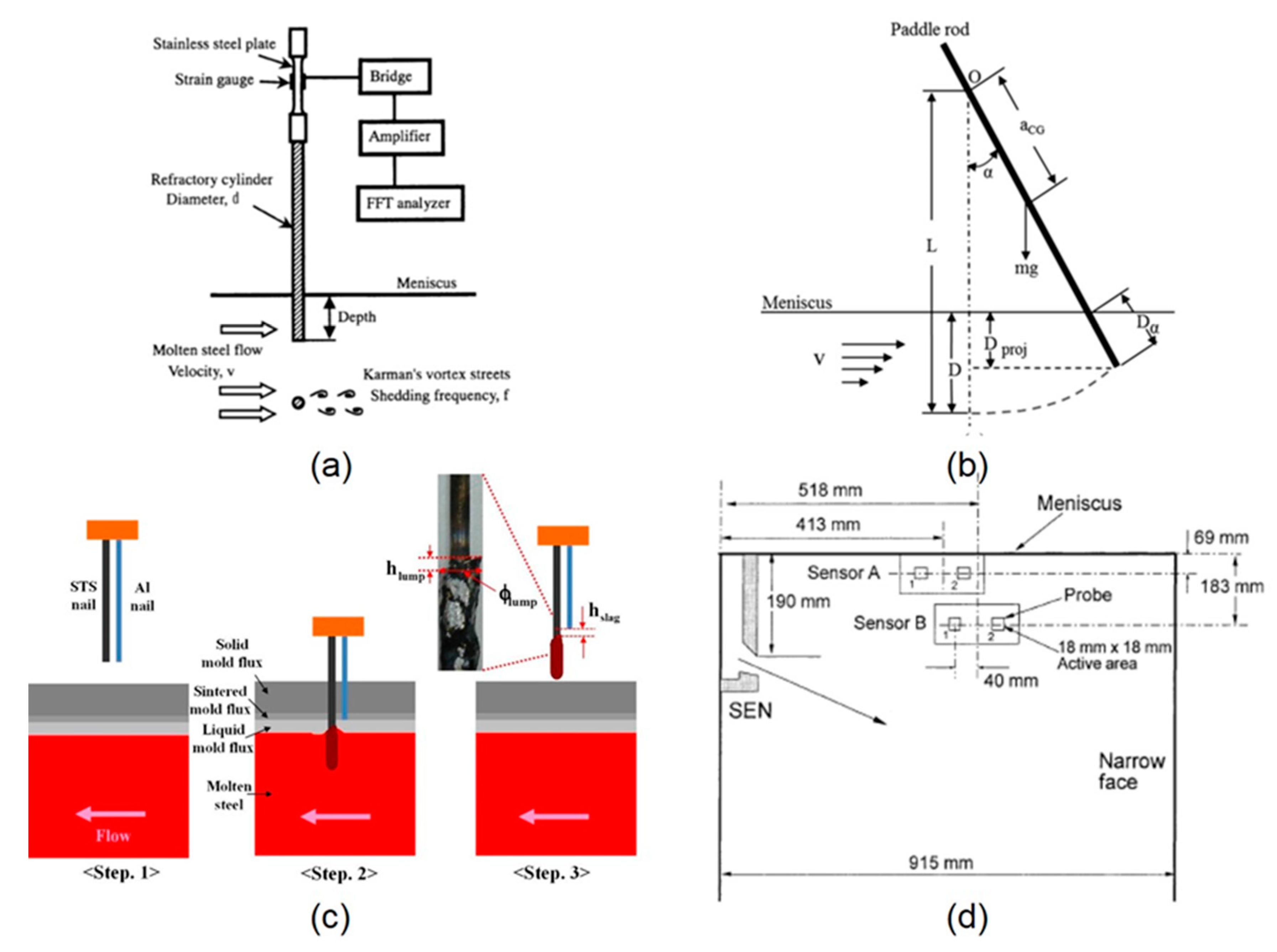
Dipping a refractory rod equipped with a strain gauge through the slag steel interface into the molten steel can be used to measure velocity near the top surface in the mold in two ways. Firstly, the average velocity near the top surface depends on the measured torque, which can be related to the drag force applied by the steel moving past the rod, averaged over time and length of the rod [39,50]. The Submeniscus Velocity Control (SVC) device is an example commercial implementation of this method [51]. Secondly, a more sophisticated method is to measure the shedding frequency of the Kármán vortices forming behind the rod, based on the frequency of the time-varying deflections, [52,53,54] as shown in Figure 2a. The vortex shedding frequency increases linearly with the fluid velocity around the rod. This method has been used to measure surface velocity from 0.05 to 0.7 m/s, which covers the range of interest in slab casting [53]. In both methods, the refractory rod should not be affected by the magnetic field or the high temperature, so should be made from an insulating, thermal shock-resistant material such as a ZrO2 coated Mo rod [39].

2.1.2. Paddle Rod Tests

Another method to measure flow velocity and direction near the mold top surface by dipping a refractory rod, into the top surface of the molten steel pool is the paddle rod test [55,56,57]. As shown in Figure 2b, one end of the rod is connected to a pivot and the other end is dipped into the molten steel pool. As the molten steel flow just near the surface impinges on and pushes the rod, it rotates around the pivot. The angle produced depends on a balance between the drag force exerted by the steel flow and the weight of the rod, which can be related to submeniscus velocity of the molten steel.

2.1.3. Nail Dipping Tests

Nail dipping tests are commonly used to quantify mold surface velocity and level due to its convenience and efficiency. This method was introduced to measure surface level profile and liquid slag layer thickness [58,59], and then extended to estimate surface velocity [60,61,62,63,64]. One or more stainless steel nails are immersed into the molten steel pool for a short time (~2–3 s) and removed. To quantify surface velocity, the shape of the solidified steel lump on the nail is measured shown in Figure 2c. The surface velocity is estimated according to [62]
U s u r f a c e = 0.624 ( φ l u m p ) 0.696 ( h l u m p ) 0.567
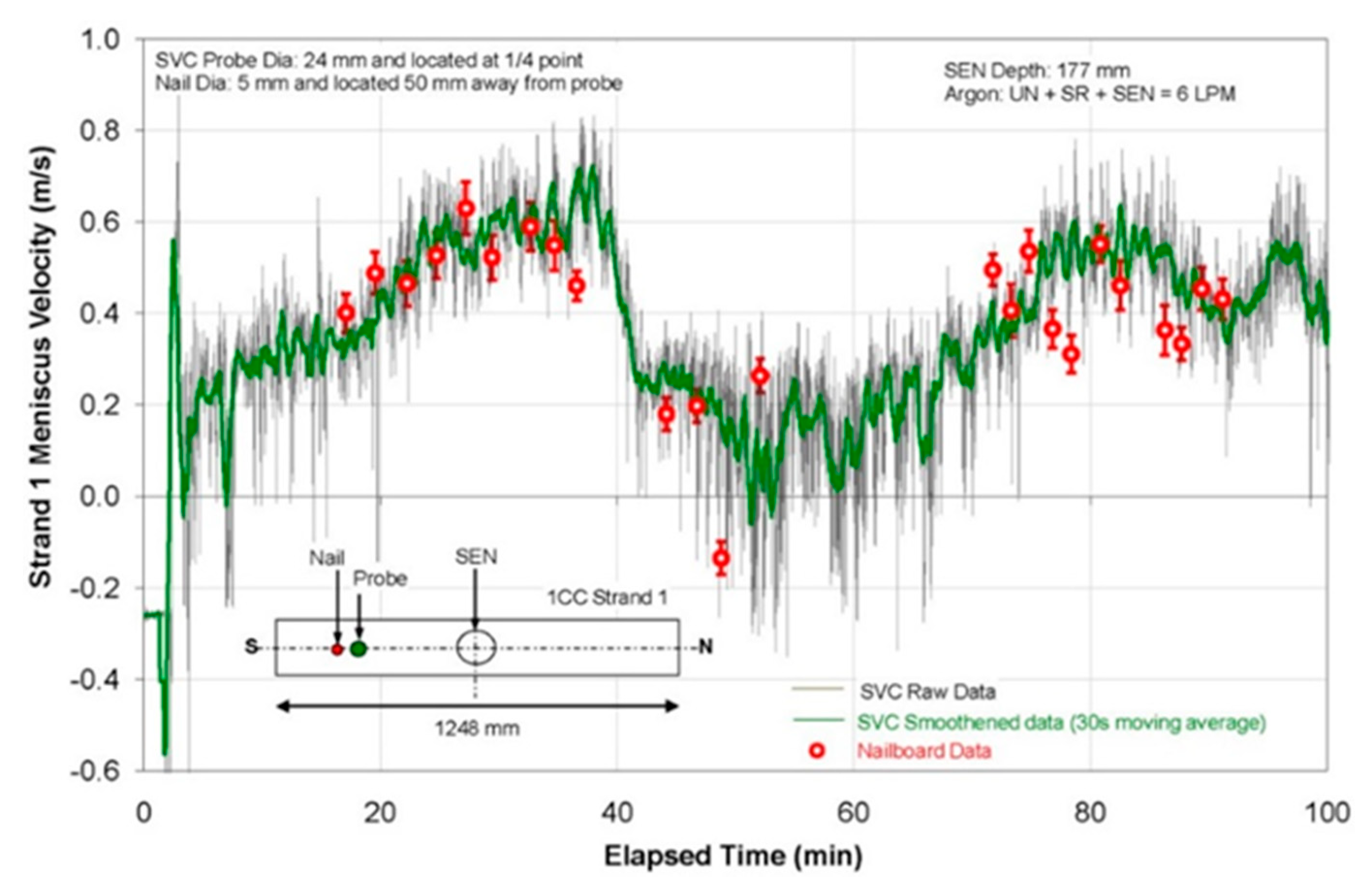
where φ l u m p is the diameter of the lump solidified on the stainless steel nail and h l u m p is the height difference built up by the flow. In addition, dipping several different nails at different times enables to quantifying transient variations of the surface velocity. The nail dipping test method shows good ability to detect surface velocity variations due to changes in casting speed, and a reasonable match with SVC measurements in a real caster [62], as shown in Figure 3.

2.1.4. Electromagnetic Mold Flow Control (MFC) Sensor Measurements

The electromagnetic MFC sensor, developed by AMEPA GmbH [65], consists of a permanent magnet and pair of highly sensitive current detectors mounted behind a copper mold plate as shown in Figure 2d for the wide face. The time delay for steel flow variations to travel between the two detectors is evaluated from the measured variations in the induced current, which is generated in proportion to the local velocity of the conducting molten steel traveling through the magnetic field [66]. The time-dependent spatially-averaged velocity near the solidification front in that region of the mold is then output knowing the distance between the two detectors. The method only works in regions where the steel generally flows across the solidification front from one sensor to the other, so the sensors should be positioned at reliable locations, such as near the meniscus between the Submerged Entry Nozzle (SEN) and Narrow Face (NF) in the Wide Face (WF) mold, or perhaps vertically in the NF mold [65,67].

2.1.5. Columnar Dendrite Angle Measurements

The tangential velocity of the molten steel across the solidification front can be estimated from the angle of the columnar dendrite growth direction [68,69,70]. As solute is washed away from the upstream side of the dendrites, they grow towards (into) the direction of the molten steel flow [69,70]. The angle of the columnar dendrites relative to the growth direction perpendicular to the strand surface increases in direct proportion to the liquid velocity, up to ~0.3 m/s [70], with further increases showing only minor effects. This indirect method enables velocity to be measured deep into the mold cavity and strand regions, where other measurement methods are not available due to the harsh environment. This method is costly as it requires microscopy on solidified slab samples [69] and may also need calibration.

2.1.6. Other Methods

Several other methods have great potential to measure velocity magnitude and/or direction of the liquid metal. One method, which has been demonstrated in laboratory tests with nonferrous alloys, is to immerse a steel sphere into the molten steel, and then measure the melting time with embedded wire(s) [71,72]. The melting rate increases with velocity, so the decrease in time to melt the sphere correlates with the flow velocity. In addition, other methods include photographic methods, reaction probes, tracer methods, electromagnetic probes, hot wire and hot film methods, dissolution methods, and fiber optic sensor measurements, which are all reviewed elsewhere [73].

2.2. Plant Measurements of Surface Level Profile and Fluctuations

Measurements of the surface level profile and its fluctuations are needed to understand transient phenomena related to surface defect formation. Especially, surface level fluctuations near the meniscus are known to cause slag entrapment during initial solidification [74]. Thus, it is important to accurately measure and control the surface level during continuous casting. Eddy current sensors are widely used to measure surface level for real-time control in the plant. Other methods to measure the surface level profile include nail board, sheet dipping, and oscillation mark measurements.

2.2.1. Eddy Current Sensor Measurements

In most casters, one eddy current sensor is located above the mold top surface to detect the transient surface level, which is sent to a flow controller (stopper rod or slide gate), to control the steel flow rate. This method is also the most common way to quantify level fluctuations. However, for best control of flow rate, it is best to measure the average liquid level, which is achieved by filtering the signal to remove high-frequency level variations produced by natural turbulence which cannot be controlled, and by placing the sensor above the most stable region (such as the quarter region in the mold with a double-roll flow pattern) [60]. Thus, this measurement underestimates the level fluctuations, especially near the narrow faces and SEN, which tend to be more severe. Moreover, level fluctuations in these regions are more important to quality problems such as deep meniscus hooks, owing to the lower molten steel temperature [56]. Thus, to measure the surface level profile, it is better to keep one senor at the most stable location (1/4 mold width) for the flow controller and to add other sensors near the narrow faces to monitor the surface level variations [75].

2.2.2. Nail Board Tests

In addition to surface velocity described in Section 2.1.3, nail dipping can also be used to measure the surface profile and its variations by using sets of “nail boards”, which are made by attaching several nails to a wood or metal board [60,64]. After dipping and removing each board, an instantaneous surface profile is made by comparing the relative heights of the steel lumps solidified on the nails [60,64]. By dipping several nail boards, transient variations of the surface profile are quantified and the surface fluctuations are calculated [60,64]. Nail dipping can also be used to measure liquid mold–flux layer thickness by adding an aluminum wire beside each stainless steel nail [59,64]. Due to the aluminum melting temperature lower than the mold flux melting temperature, the height difference between the steel lump and the aluminum wire end, hslag correlated with the liquid mold-flux layer thickness as shown in Figure 2c. The slag layer thickness can also be revealed by the location of the colored bands of scale that form on each nail [76].

2.2.3. Sheet Dipping Tests

Dipping a thin sheet of steel into the top surface is an alternative method to nail boards to determine the profile of the liquid mold flux/molten steel interface. Time averages and standard deviations of the transient interface profiles, revealed by serial dipping of the sheets, are useful to validate transient computational model predictions [77].

2.2.4. Oscillation Mark Measurements

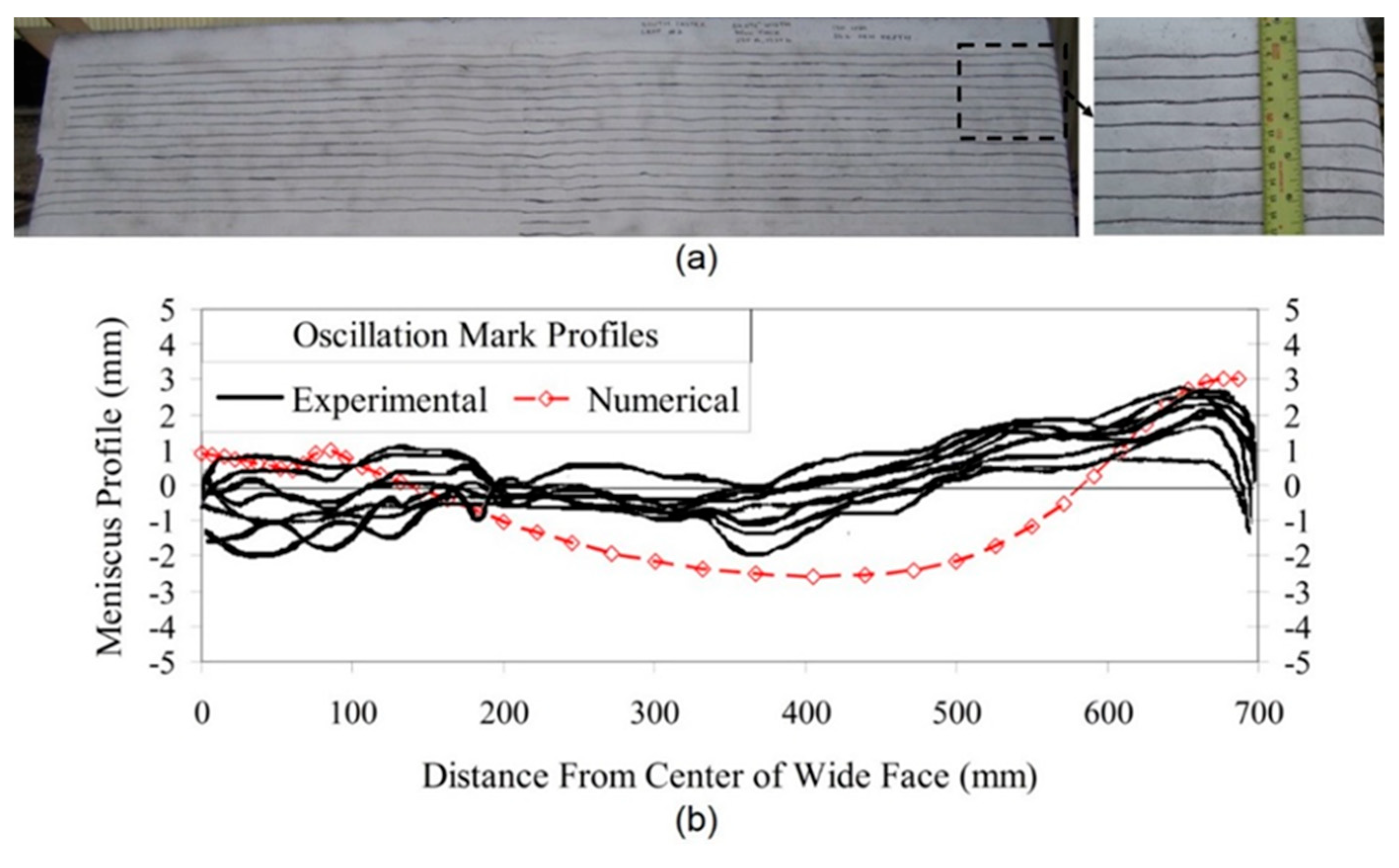
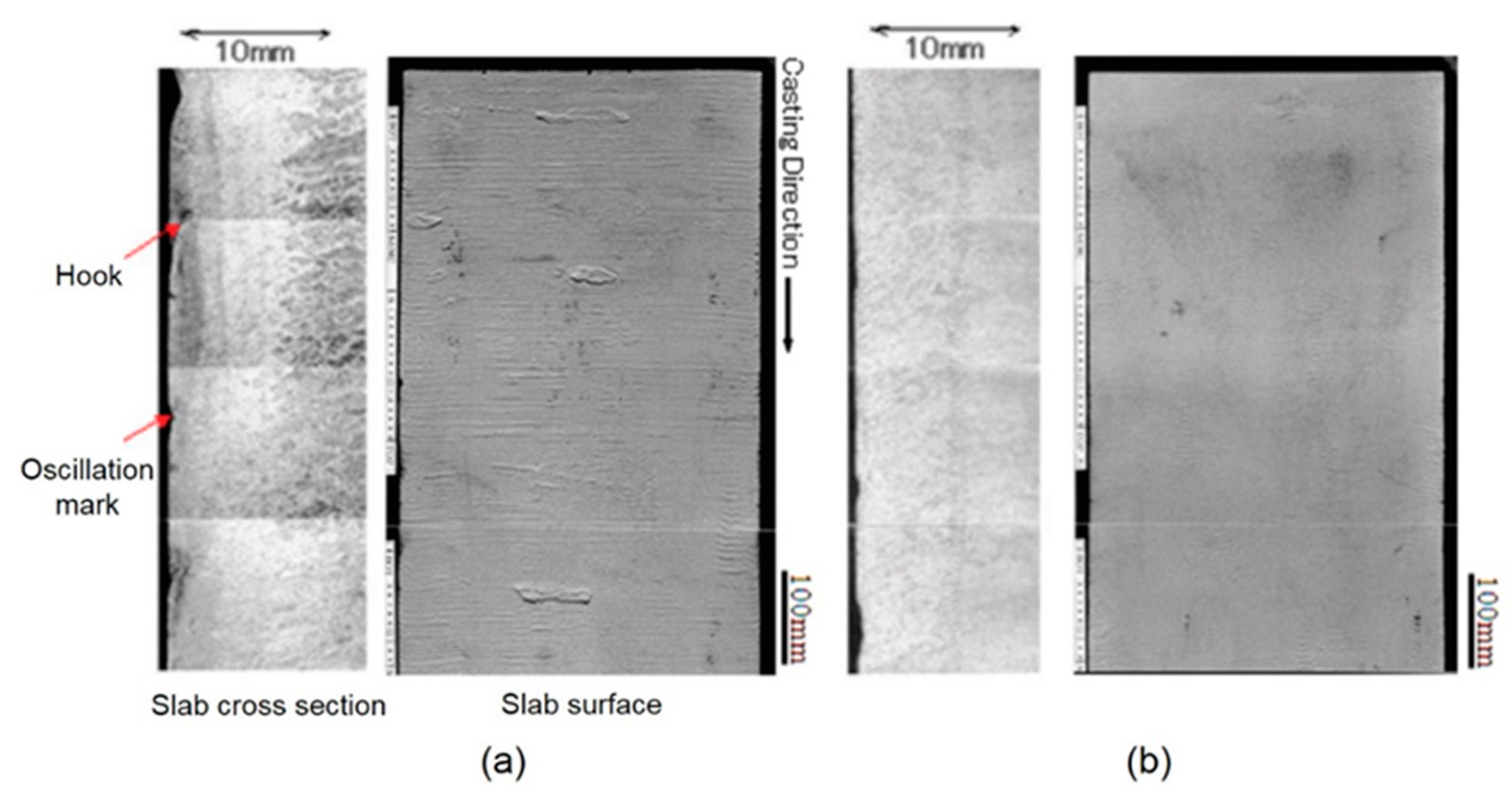
Partial overflow and freezing of the molten steel over the meniscus produces an oscillation mark during each mold oscillation cycle. The oscillation mark appears as a small transverse depression in the surface of the solidified steel slab. Thus, each mark represents the instantaneous profile of the interface between the liquid mold flux and molten steel around the mold perimeter at the time it formed. Tracing and graphing a series of oscillation marks accurately reveals the transient liquid mold flux/molten steel interface profiles, such as shown in Figure 4a. These measured profiles can be used to validate computational models of time-dependent (Figure 4b) meniscus level profiles and their fluctuations [61].

2.3. Plant Measurements of Particle Capture

Particles, including argon bubbles, alumina, and slag inclusions, can be entrapped by the solidifying steel shell during continuous casting, and are greatly affected by the flow pattern, and EM effects. This results in surface and/or internal defects on the final steel products. Thus, it is important to quantify particle capture defects in as-cast steel slabs. Many different measurement methods are available, including ultrasonic testing, step milling, and other methods which are reviewed elsewhere [78].

2.3.1. Ultrasonic Testing (UT) Measurements

The locations of particles entrapped by the steel shell, can be measured in a steel slab in width, length, and depth directions, by using an ultrasonic detection system [79,80]. Recently, the dead zone, which is produced by reflected waves on the outer surface of the steel slab, has been reduced by using a V-shaped receiving probe and transmitting probe system with acoustic shielding between the probes [79]. This enables the detection of captured particles from 2 to 10 mm beneath the slab outer surface [79].

2.3.2. Step Milling Measurements

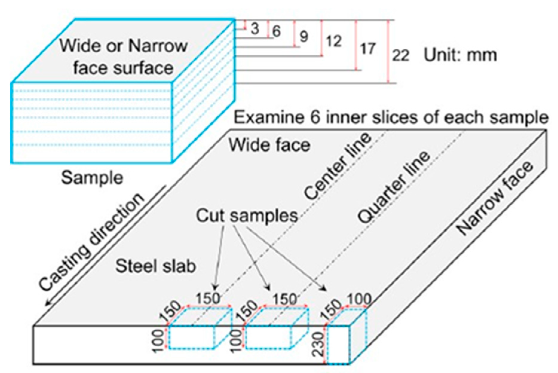
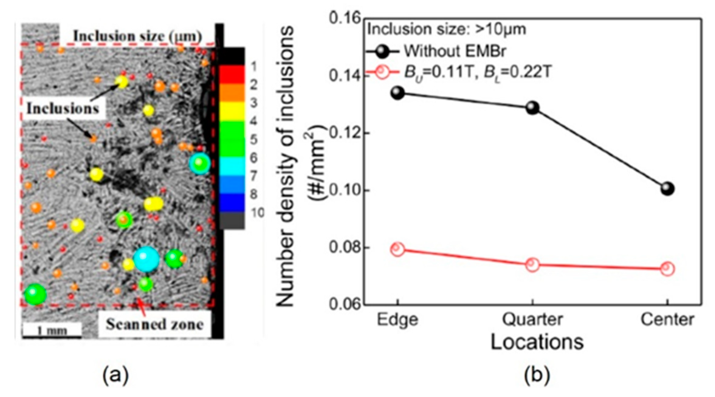
Step milling followed by microscopy, with automated surface scanning for particles, such as the ASPEX system [81], is a useful method to quantify both the location and size of particles captured into the solidifying steel shell [82]. Samples are cut from wide and narrow faces of an as-cast steel slab. The outer surface of each sample is milled away layer by layer, using an optical microscope to find and examine each particle observed on each exposed surface and recording the size and location of each particle. This procedure has been used to measure inclusions in slab samples in previous work [82,83], such as shown in Figure 5. Compared to the UT method, the step milling method is more difficult and expensive; but, step milling can quantify further details of the captured particles such as their shape and composition, in addition to their size and location.

2.3.3. Other Methods to Measure Particle Capture

Many other methods to measure size distribution, morphology, and composition of non-metallic oxide inclusions in the molten steel have been developed as reviewed elsewhere [78]. Direct methods include section method, volume method, extraction, and liquid evaluation methods. Section methods include Metallographic Microscope Observation (MMO), Image Analysis (IA), Sulfur Print, Scanning Electron Microscopy (SEM), Optical Emission Spectrometry with Pulse Discrimination Analysis (OES-PDA), Laser Microprobe Mass Spectrometry (LAMMS), X-ray Photoelectron Spectroscopy (XPS), and Auger Electron Spectroscopy (AES). Volume methods include Conventional Ultrasonic Scanning (CUS), Mannesmann Inclusion Detection by Analysis Surfboards (MIDAS), Scanning Acoustic Microscope (SAM), X-ray Detection, Slime (Electrolysis), Electron Beam (EB) melting, Cold Crucible (CC) melting, and Fractional Thermal Decomposition (FTD). Extraction methods include Coulter Counter Analysis, Photo Scattering Method, and Laser Diffraction Particle Size Analyzer (LDPSA). Inclusion evaluation methods in the liquid include Ultrasonic Techniques for Liquid System, Liquid Metal Cleanliness Analyzer (LIMCA), and Confocal Scanning Laser Microscope. In addition to these direct methods, indirect ways to estimate inclusion content include measurements of total oxygen, nitrogen pickup, dissolved aluminum loss, alumina pickup in the slag, and Submerged Entry Nozzle (SEN) clogging, which are easier and less costly [78].

2.4. Lab Scale Modeling

Water modeling is a useful tool to simulate fluid flow phenomena of continuous steel casting due to kinematic viscosity of water similar with that of molten steel. However, the negligible electrical conductivity of water (See Table 1) prevents the study of magnetic forces that change the flow. Instead, physical devices to mimic the flow effects of electromagnetic forces have been applied to simulate stirring via two pairs of tuyeres that produce jets, and braking via a layer of beads suspended between screens that resist flow [84,85].
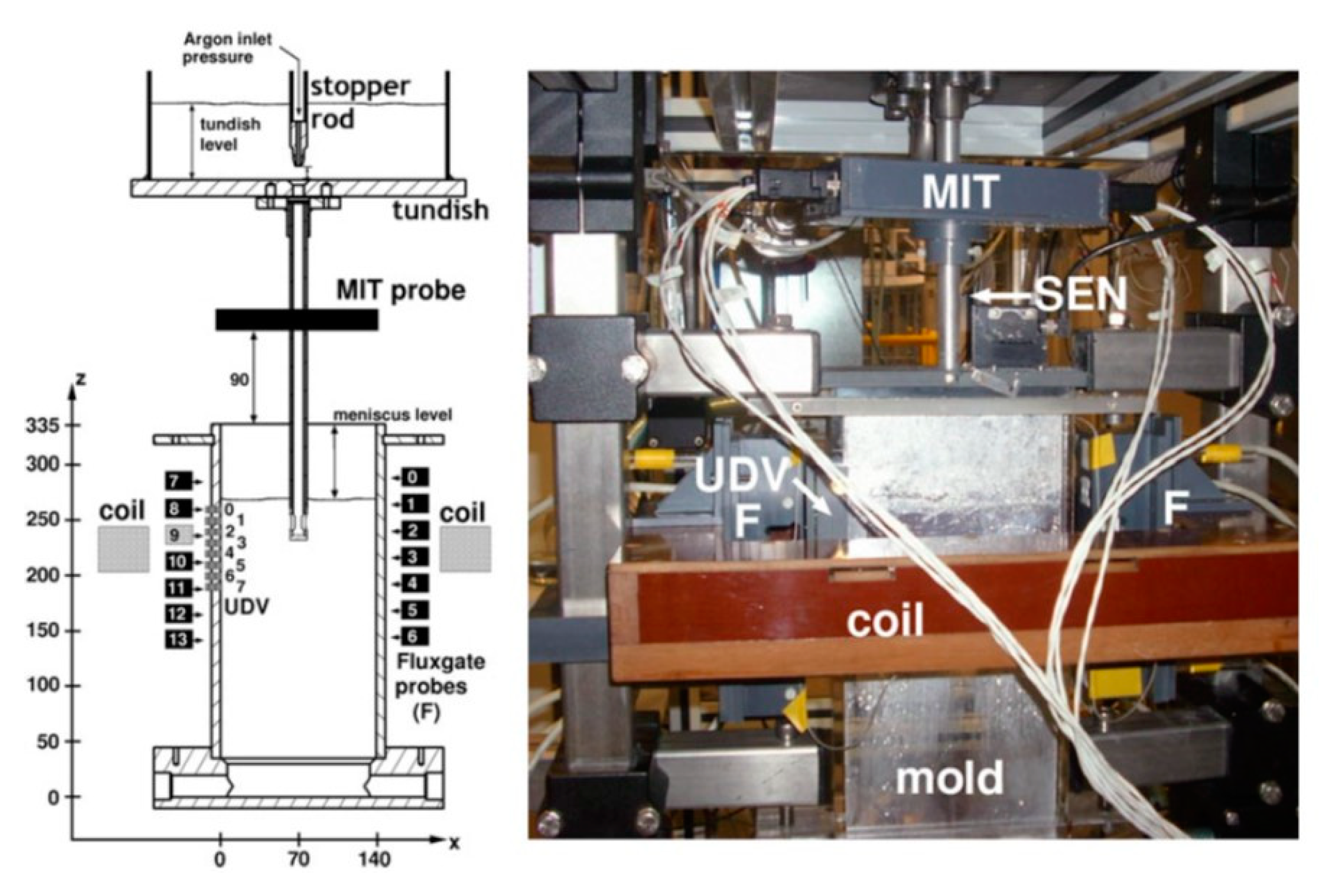
A more accurate method is to use low melting temperature alloys such as mercury, Sn60Bi40, or eutectic Ga68In20Sn12 alloy, in physical models, which have the benefits of being conductive to simulate induced flow from electromagnetic fields, having high surface tension and nonwettability of molten steel to simulate multiphase flow, and being liquid at or near room temperature for easy measurements (Table 1) [86]. Lab scale modeling with these liquid metals can use Ultrasound Doppler Velocimetry (UDV) and Mutual Inductance Tomography (MIT) probes to map internal velocity fields, as applied to single-ruler EMBr fields in a slab casting mold [86,87,88], such as shown in Figure 6 [87].
To maintain similarity between the low melting temperature alloy modeling and real caster conditions with electromagnetic forces, magnetohydrodynamics (MHD) dimensionless numbers, such as Hartmann number (Ha) and/or Stuart number (N), should be considered in addition to the standard fluid dynamics dimensionless numbers Froude number (Fr), Reynolds number (Re), and Weber number (We) for scaled physical models.
One way to obtain reasonable predictions of the real caster (R) from measurements in the lab scale model (M) when electromagnetic effects are present is to match both Fr and N. If the lab scale model stays fully turbulent, and multiphase flow is not dominant, then Re and We similarity is not critical [89]. First, Fr, which represents the ratio of inertial to gravitational forces, should be maintained the same in the scaled model and real caster, as follows
V M g L M = V R g L R
where V is a characteristic flow velocity, g is gravitational acceleration, and L is a characteristic length scale; “characteristic” refers to any pair of corresponding values in the model and real caster. This match can be achieved by choosing the casting speed in the model, VCasting, M, by rearranging Equation (2):
V C a s t i n g ,    M = V C a s t i n g ,    R L M L R
Velocity anywhere in the real caster is then estimated by multiplying the measured velocity at the corresponding position in the scaled model by L M L R , according to Equation (2).
In addition, N, the ratio of electromagnetic to inertial forces, should be maintained constant, as follows
( σ M ρ M ) ( B M ) 2 L M V M = ( σ R ρ R ) ( B R ) 2 L R V R
where σ is electric conductivity and ρ is density, as given in the property term. One way to achieve this match is to choose the magnetic field intensity in the model, B M , as follows, which is found by rearranging Equation (4):
B M = B R ( ρ M ρ R σ R σ M ) 0.5 ( L R L M ) 0.5 ( V M V R ) 0.5
To match both Fr and N in the scaled model and the real caster, BM can be chosen as follows
B M = B R ( ρ M ρ R σ R σ M ) 0.5 ( L R L M ) 0.25
which is found by replacing V M / V R in Equation (5) with L M / L R , according to Fr in Equation (2). This approach was used successfully with a mercury model to investigate fluid flow velocities in a slab mold with static magnetic fields (local EMBr and single-ruler EMBr) during continuous casting [90].
Alternatively, it is possible to obtain reasonable predictions of the real caster from lab scale measurements on molten metal with electromagnetics, without matching Fr [27]. In this method, the casting speed in the model, V C a s t i n g ,    M is chosen to match N, by rearranging Equation (4) as follows
V C a s t i n g ,    M = V C a s t i n g ,    R ( ρ R ρ M σ M σ R ) ( L M L R ) ( B M B R ) 2
With this method, velocity anywhere in the real caster is then predicted by multiplying the measured velocity at the corresponding position in the scaled model by ( ρ R ρ M σ M σ R ) ( L M L R ) ( B M B R ) 2 , according to Equation (4). In addition, surface level in the real caster, l R , is estimated from the measured surface level in the model, l M , by applying the Froude number based scaling method, as follows [27]
l R = l M ( L R L M ) 0.5 ( V R V M )
Using this method, the flow pattern, velocities, and surface level predicted in a real caster matched well with both measurements and Large Eddy Simulation (LES) modeling of a scaled Ga68In20Sn12 model [27]. In particular, the surface level in the real caster estimated with the Fr based scaling method (Equation (8)) showed much better agreement than a simple method of multiplying the measured surface level by the scale factor, L R / L M [27].

2.5. Computational Modeling: Magnetohydrodynamics (MHD) Models

Many studies of fluid flow-related phenomena in continuous steel slab casting have been conducted using three-dimensional Computational Fluid Dynamics (CFD) models, as reviewed previously [22,23]. These models solve the continuity equation for mass conservation and the Navier–Stokes equations for momentum conservation of incompressible Newtonian fluids, such as molten steel. To simulate other important phenomena, these flow equations are solved together with further coupled equations including turbulence equations, such as Reynolds-averaged Navier-Stokes (RANS)-based standard k-ε [91], Shear-Stress Transport (SST) k-ω [92], or LES-based subgrid-scale viscosity models such as the Wall-Adapting Local Eddy (WALE) model [93]; multiphase fluid flow equations [22] using the mixture, Eulerian, or Volume Of Fluid (VOF) methods; Lagrangian particle transport model such as the Discrete Phase Model (DPM); and advanced particle-capture criterion equations [82,94]. These equations are solved using classical finite-volume or finite difference methods, often with a commercial CFD package program, such as the ANSYS Fluent code [95], or an in-house code, such as the multi-GPU-based CUFLOW [96].
To consider effects of electromagnetic forces on fluid flow-related phenomena and Magnetohydrodynamics (MHD) models [97,98] are incorporated into the CFD models by adding a Lorentz force term to the momentum equation. Conducting fluid moving in applied magnetic fields induces current and the induced current and the magnetic fields generate Lorentz forces on the fluid flow. There are two methods including magnetic induction method and electrical potential method to calculate the Lorentz force term, as follows.
The total magnetic field, B consists of applied magnetic field, B0, and induced magnetic field, b.
B = B 0 + b
Next, to find B and the induced current density J, the magnetic induction method first finds B by solving the magnetic induction equation, derived by combining Ohm’s law, Faraday’s equation, and Ampère’s law:
B t = × ( u × B ) + 1 μ σ 2 B
where t is time, u is fluid flow velocity, μ is magnetic permeability, and σ is electrical conductivity of the fluid. Knowing B, the induced current density Ampère’s equation is then solved for J:
J = 1 μ × B
The other method to find J and B, the electric potential method, first assumes that B can be approximated by B0. This assumption is good for systems with high magnetic diffusion compared to magnetic induction, such as continuous casting, where the induced magnetic field b is small relative to the applied field, B0. With this electromagnetic condition, a Poisson equation for electric potential, φ can be derived from Ohm’s law and conservation of charge, · J = 0 , as given by Equation (12).
2 φ = · ( u × B 0 )
Then, from the calculated φ , the induced current density is found from Equation (13).
J = σ ( φ + u × B 0 )
Finally, in both methods, the Lorentz force, F L is calculated from the calculated current density and magnetic field as follows
F L = J × B
Note that the magnetic field is always perpendicular to the flow direction due to the right-hand rule. The force direction is perpendicular to both the induced current density and the magnetic field, according to the cross product in Equation (14). Together, this means that the force direction is 180o, or directly opposite to the flow direction, so is intrinsically a braking force. The actual effect on the flow is much more complicated, however. For a static magnetic field, mass conservation often makes the flow deflect around a region of local magnetic field braking, and as a result can produce faster flow in another region. For a time-varying field, the apparent movement of the field created by a consistent phase shift in a series of magnetics can create an apparent motor force that can almost match the flow direction in some cases.
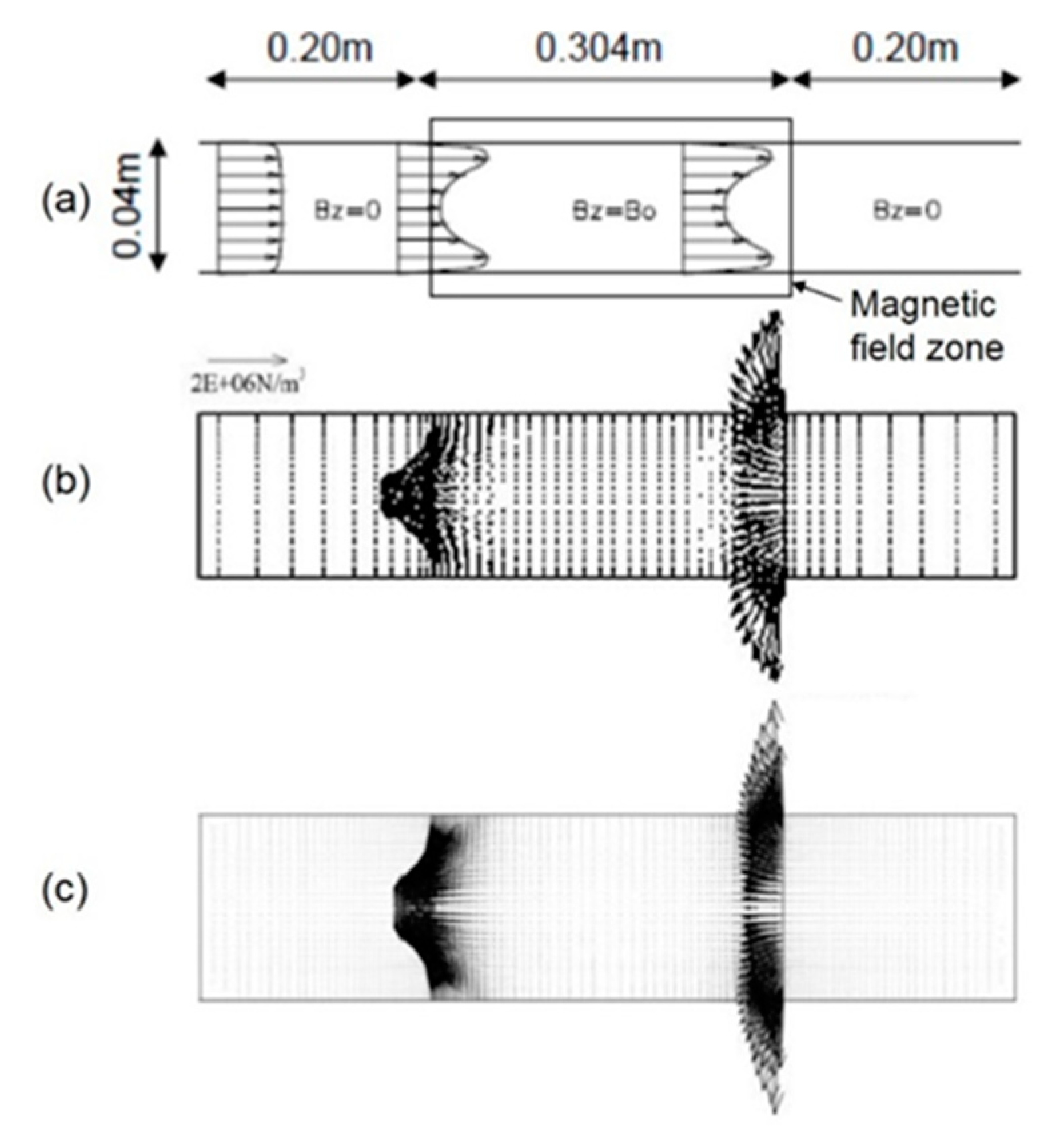
Regardless of the computational method, model validation is essential. A classic test problem for MHD CFD involves turbulent flow (Re ~40,000) in a channel with a constant static magnetic field applied uniformly over a 304-mm-long rectangular region near its center. Lorentz forces in the channel domain are shown in Figure 7. Vectors of Lorentz force predicted with both the electric potential method [99] and the magnetic induction method [61] match.
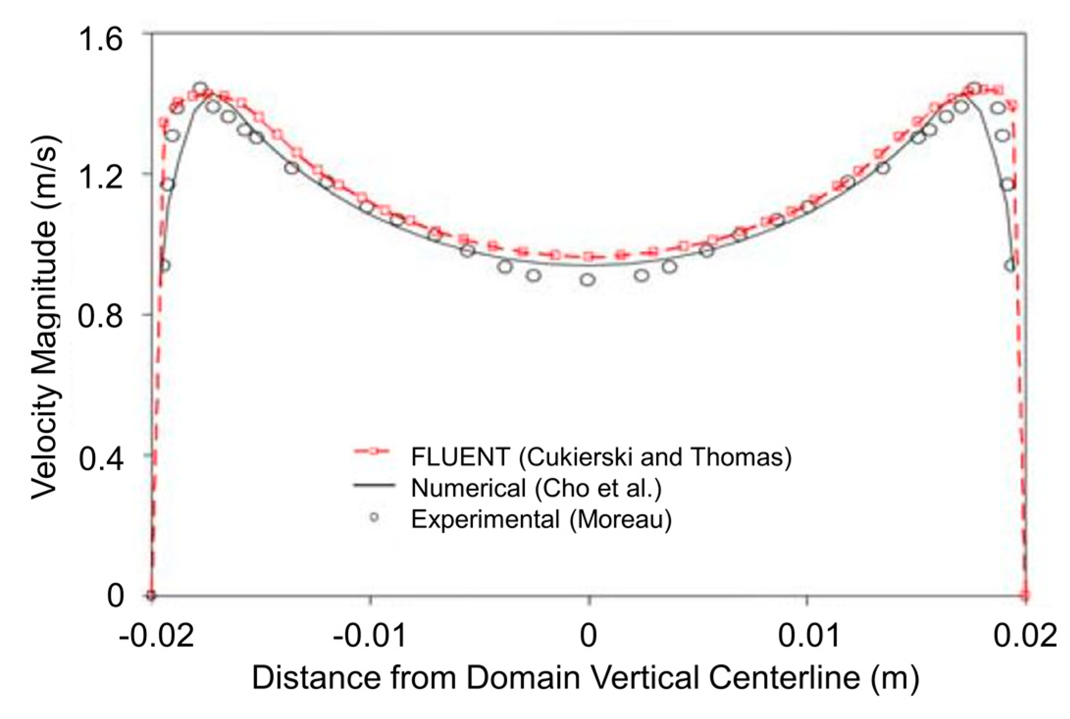
In addition, model predictions of velocity profile across the channel cross section should match with the experimental measurements, such as shown in Figure 8 [61]. An M-shaped profile is observed with higher velocities near the channel walls and lower velocities towards the center region of the channel. This is because the Lorentz forces slow down the flow in the center region, while flow accelerates near the walls to conserve mass. Validation with a test problem such as this one demonstrates that a given MHD CFD model can enable accurate investigation of the effect of electromagnetics on flow in continuous steel casting.

3. Electromagnetic Effects on Fluid Flow Pattern

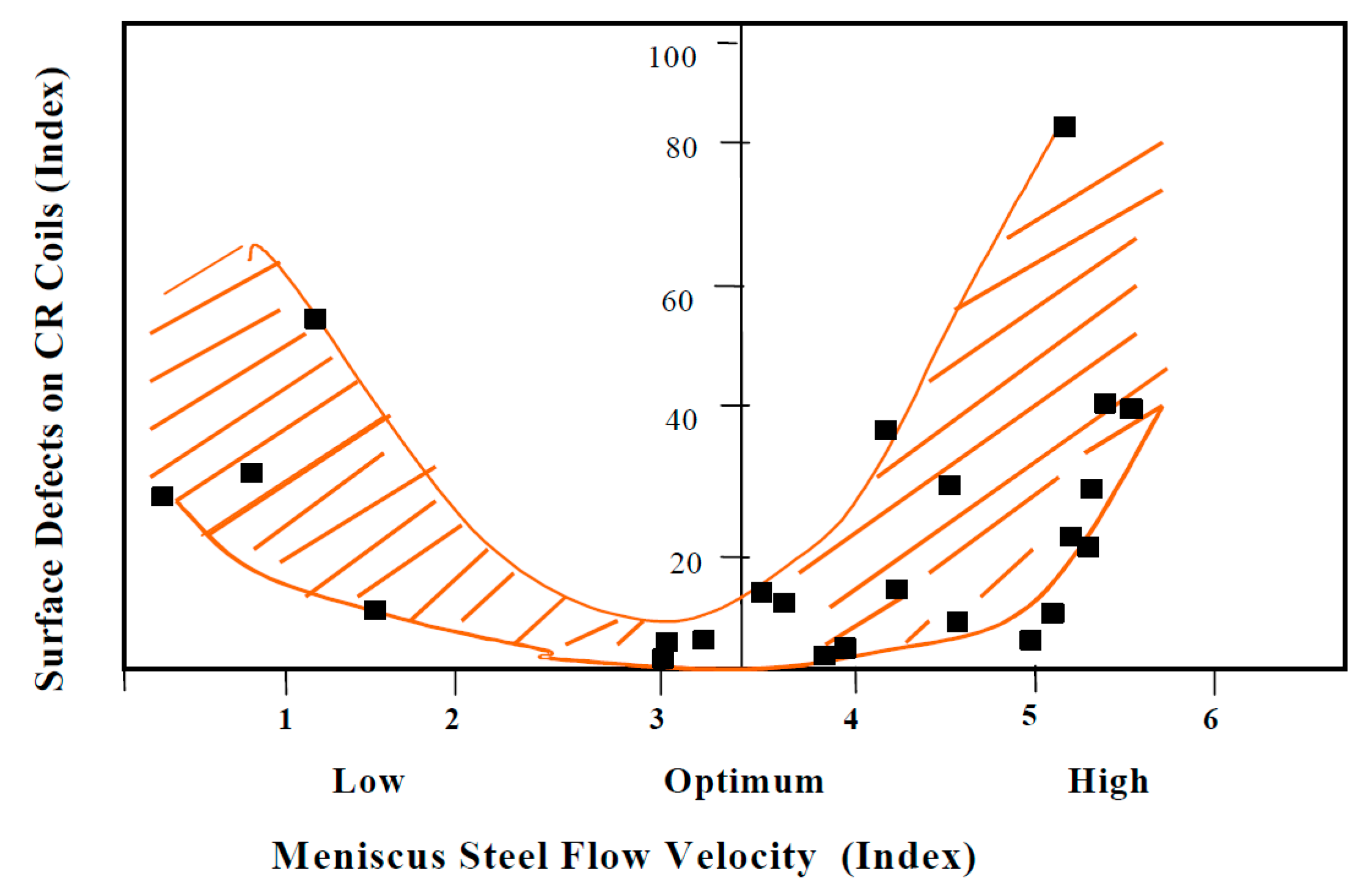
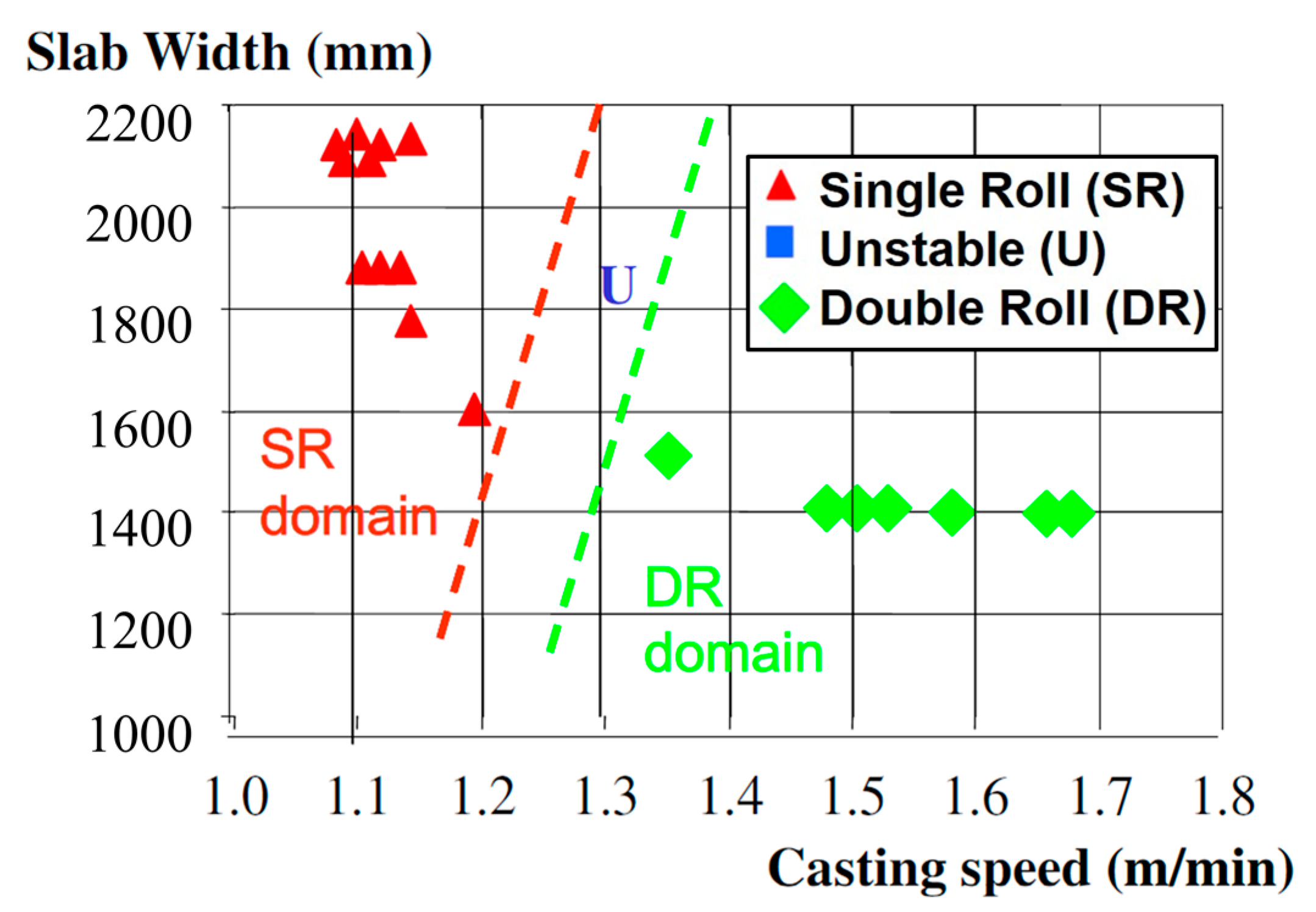
The quality of continuously-cast steel slabs depends greatly on fluid flow phenomena including the flow pattern, which governs jet impingement, turbulence, surface velocity, and level variations in the mold region of the process. Excessive surface velocities, and the accompanying turbulence, large surface profile variations, and surface level fluctuations, can cause the entrainment of slag into the molten steel pool, which may lead to the entrapment of inclusions by the solidifying steel shell, and defects in the final product [74]. On the other hand, abnormally slow surface flow can result in low and nonuniform liquid temperature near the meniscus and problems associated with low superheat, which include insufficient slag melting and infiltration, meniscus freezing, and hook formation, leading to surface defects in the product [100,101]. Thus, process parameters must be controlled within optimum windows [16,32] of process operation, as shown in Figure 9 for data measured at NKK Corporation [16], to avoid these quality problems [2,16].
The flow pattern significantly affects many important phenomena in the slab mold and upper strand regions. Flow in the mold can be classified as having single-, double-, or unstable flow patterns [2,16]. Unstable flow often involves chaotic transient transitions between single- and double-roll, and should be avoided because it is the worst for steel quality, owing to severe surface instability during the flow transitions [2,16]. Electromagnetic control of the flow pattern aims to maintain a stable double-roll flow pattern that keeps surface velocity within an optimum range for best steel quality [16,32].

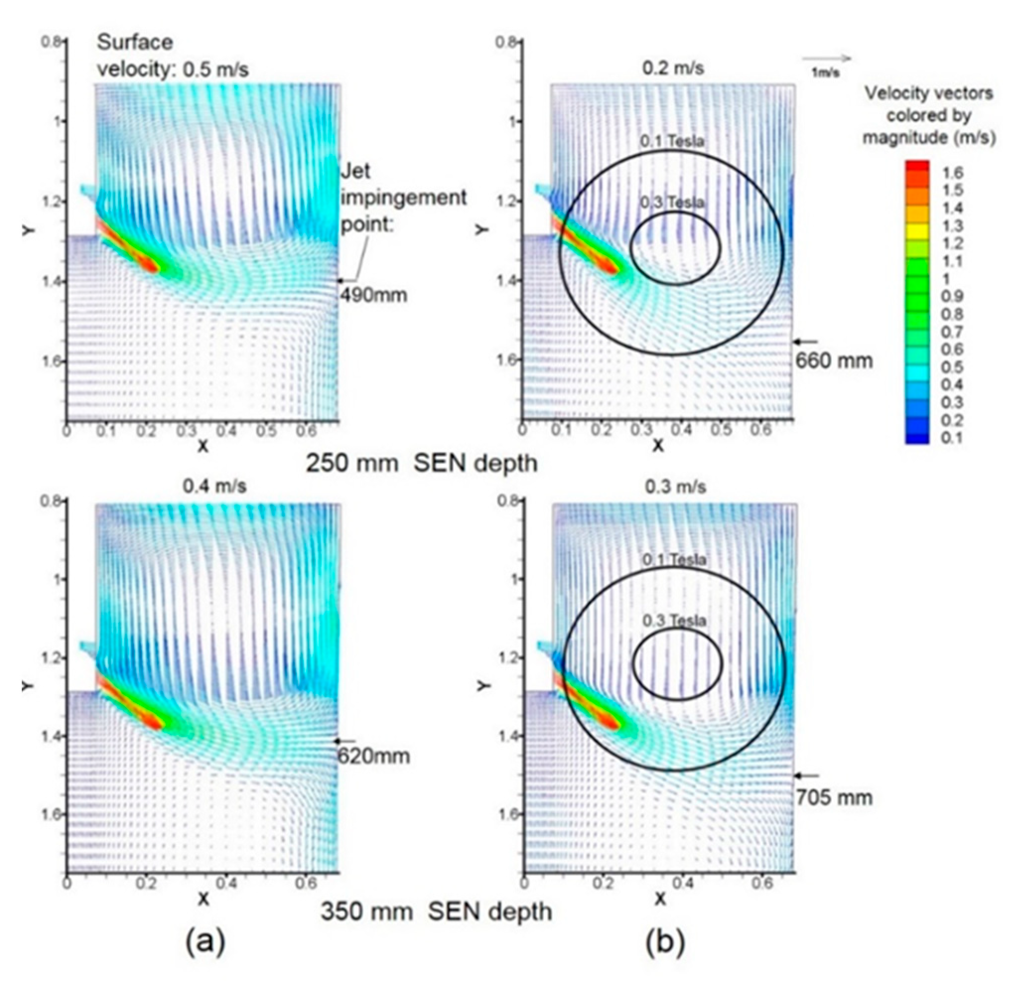
3.1. Local EMBr

Local EMBr creates roughly circular-shaped static magnetic fields near the nozzle ports. The fields are designed to make the jet pass below the strongest core region of the magnetic field and deflected downward [24]. This results in deeper jet impingement on the narrow face, slower surface flow, and a flatter surface profile [61,102,103], as seen by comparing Figure 10a,b. These surface-flow braking effects become stronger with higher EMBr strength [102]. Note that excessive EMBr strength may produce too low surface velocity which could cause the meniscus freezing and hook formation associated with low surface temperature due to the stagnant surface flow.
On the other hand, local EMBr causes the jet to deflect upward if the jet passes above the strongest region of the magnetic field [104]. This produces shallower jet impingement on the narrow face, higher surface velocity and larger variations in surface profile across the mold width [104]. Abnormally strong local EMBr fields may change the mold flow pattern from a double-roll to a single-roll pattern, making the jet directly go towards the surface without impinging first on the narrow faces [103]. This is usually detrimental to surface quality, and may also cause slag entrainment and other defects.
Thus, properly locating local EMBr field relative to the nozzle ports and optimizing the field strength is important to achieve surface flow conditions in a safe window of operation [105]. In addition to the EMBr magnetic field position, this also requires consideration of the SEN depth [61], nozzle port angle [90], and slab width [106] that strongly affect the jet behavior in the mold. As shown by comparing the two frames in Figure 10b, the EMBr effects on braking surface flow are weakened if the jet passes below the magnetic field region due to deeper SEN location, which leads to less deepening of the jet impingement point and less reduction in surface velocity. This trend is contrary to that without EMBr where surface velocity deceases with increasing SEN depth, as shown in Figure 10a. It is important to carefully monitor and control the SEN depth and field strength according to the casting conditions and the EMBr field location.

3.2. Single-Ruler EMBr

Single-ruler EMBr systems are designed to slow down the mold surface flow by applying a horizontal rectangular-shaped static field across the entire width of the slab mold region near the meniscus [25]. With increasing casting speed, surface flow tends to be stronger, so stronger electromagnetic braking is needed, such as in thin-slab casting at high casting speed [107,108]. This is useful to avoid excessive surface velocities and vortex formation [26], which can cause slag entrainment into the molten steel pool in the mold. Compared to local EMBr, single-ruler EMBr is more effective to brake the surface velocity in the mold because the magnetic field shape of single-ruler EMBr extends across the entire width, including the center and the narrow face regions [90]. However, excessive application of single-ruler EMBr near the meniscus can be detrimental by slowing surface velocities too much for the casting conditions. This can result in excessive cooling of the meniscus region and insufficient mixing of the surface slag layers, leading to meniscus freezing, where the accompanying subsurface hooks can capture particles including argon bubbles, alumina inclusions, and mold slag droplets into the solidifying steel shell, leading to surface defects.
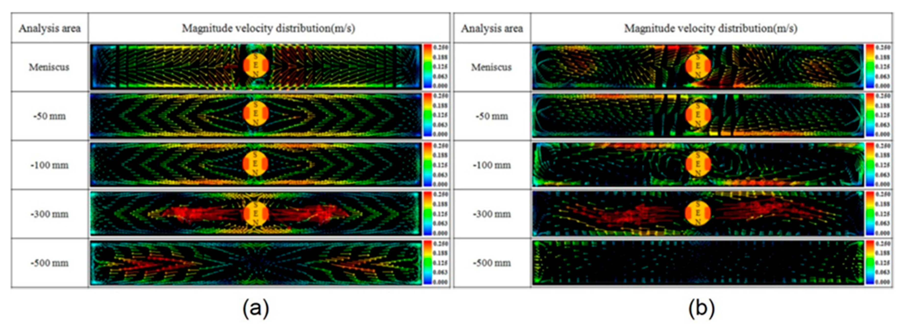
On the other hand, placing the single ruler below the nozzle can increase surface velocity [27,28,29]. In this case, the field deflects the downward-flowing jet to become more horizontal, impinging higher on the narrow face, and causing more and faster flow up the narrow faces towards the meniscus. This can help by increasing surface velocity into the optimal range in some situations such as thick slab casting at low casting speed. Care should be taken to avoid locating the maximum of the magnetic field directly across the nozzle ports, as this produces flow instability resulting in severe jet wobbling and surface fluctuations, as discussed further in Section 4.1 [27,28,29]. The strong horizontal field also tends to lessen mixing between the upper and lower recirculation zones of the double-roll flow pattern. This is useful during casting of clad steels, where the field is positioned between two nozzles which deliver two different steel grades, as discussed later [30].
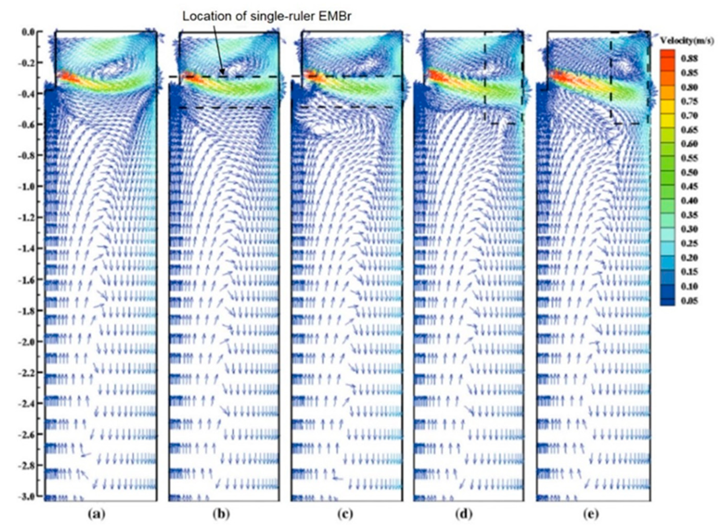
Vertical single-ruler EMBr, recently proposed, is designed to decrease surface velocity and surface profile variations by imposing two strong static ruler-shaped magnetic fields oriented vertically near the narrow faces [109,110,111]. The flow velocity up the narrow face is predicted to become slower and more uniform with vertical EMBr [110]. This is proposed to be useful for high-speed thin-slab mold casting, to avoid excessive surface flow problems. If the flow has a double-roll pattern with a downward jet, then the vertical ruler field is predicted to reduce surface velocity more than a horizontal single-ruler EMBr field [109,110], as shown in Figure 11.

3.3. Double-Ruler EMBr

Double-ruler EMBr combines two horizontal rectangular-shaped static ruler magnetic fields across the mold width: one (upper ruler) above and the other (lower ruler) below the nozzle ports [24]. The upper ruler tends to decrease surface velocities and surface level variations across the mold width [17,29,112,113,114]. This ruler acts in several ways: stabilizing flow inside the nozzle, deflecting the jets exiting the ports downward, especially when the ruler is located just above the nozzle ports, which slows the flow up the narrow faces and finally by slowing the flow along the meniscus [29,112,113,114]. The lower ruler generally tends to lessen the jet penetration depth [17,79,114,115,116,117,118,119], which affects particle transport deep into the mold cavity, as discussed in Section 6.2.
Compared to local and single-ruler EMBr systems, the double-ruler EMBr has more flexibility, with independent control of the strength of two rulers offering better potential to optimize the flow pattern, by either increasing or decreasing the intensity of surface flows. However, nonoptimal choice of the ruler intensities has the potential to worsen quality problems. Excessive upper-ruler strength can make surface flow too slow, especially in low-speed operations, resulting in meniscus freezing and hook formation, which is detrimental to the slab surface quality. Alternatively, excessive lower ruler field strength could lead to excessive surface velocities, turbulence and associated defects, especially in high-speed operations.
The ruler-shaped field often tends to decrease in strength towards the narrow faces. If the strength of the lower ruler near the narrow faces is too small, then the effect of the upper ruler deflecting the jet downwards can increase flow down the narrow faces below the mold, resulting in deeper jet penetration and associated particle defects [113]. In addition, this problem may decrease flow towards the surface, resulting in slower surface flows and associated stagnation problems, even with a strong lower-ruler field and no upper field current. This is because the double-ruler still generates a magnetic field peak above the nozzle that can deflect the jet downward, which differs from the single-ruler EMBr field below the nozzle ports [17].
Finally, confining the jet between the upper and lower rulers tends to make the jet thinner, slightly faster, and with less vertical variations [113]. Thus, the locations and strengths of the double-ruler EMBr system should be adjusted to achieve optimal mold flow, keeping the surface flow velocity within the optimal range, and minimizing jet penetration deep into the mold cavity, in order to improve both surface and internal quality of steel slabs.

3.4. MM-EMB

By adjusting the strengths of the five local static fields, multi-mode EMB can be designed to change, and hopefully improve flow velocity and stability in several different ways [31,120]. With two strong local magnetic fields located near the meniscus near the narrow faces and an optional strong field just below the nozzle, MM-EMB in braking mode 1 or damping mode tends to slow down surface flow [31,120], and lessen surface level fluctuations, in order to avoid defects associated with excessive surface velocity, such slag entrainment.
Alternatively, applying two strong local magnetic fields below the nozzle near the narrow faces, MM-EMB in braking mode 2 can achieve similar flow behavior. This mode is similar to single-ruler EMBr positioned below the nozzle, except there is no field in the center of the mold below the nozzle. The observed decrease in surface flow is likely due to the field cores being positioned above the jets near impingement on the narrow faces. Care should be taken in positioning the fields, however, because if the two fields are located below the jets near narrow-face impingement, surface flow would be expected to increase. Thus, this mode likely experiences similar behavior and operation guidelines as the local-EMBr field discussed in Section 3.1. Other MM-EMB modes are possible, which deserve further investigation.

3.5. Moving Fields: EMLS, EMLA, EMRS, M-EMS, EMC, and SEMS

Moving electromagnetic fields are generated by passing alternating currents through a series of magnets, each having a different phase shift in order to create a traveling Lorentz force to actively drive the flow tangentially across the surfaces of the solidifying steel shell in the mold. The strength and direction of the force depends on the magnet orientation, the applied current, and the effective frequency of the phase shift. Three types of horizontally-moving magnetic fields near the nozzle ports are EMLA [16,32,33,40,51,56,121], EMLS [16,32,33,40,51,56,122], and EMRS [16,32,33,40,51] or M-EMS [123,124]. Alternatively, EMC applies vertically-moving magnetic fields near the meniscus [36,37,38]. Other types of moving field systems—SEMS and S-EMS—are applied to the strand below the mold [33,40,41,42,43,44,45,46,47].
When surface flow is too slow, EMLA is designed to accelerate the jets in order to increase the surface velocity, turbulence, and surface temperature. This is useful for situations, such as low-speed casting and wide molds, to prevent stagnant surface flow, meniscus freezing, and the corresponding surface defects [121]. Also, EMLA can be applied when argon gas flow rate is high, to transform a detrimental single-roll pattern to a better double-roll pattern [32].
Alternatively, when surface flow is too fast, EMLS can slow down the jets in order to decrease surface velocity, surface profile variations, level fluctuations, and associated quality problems such as slag entrainment [32]. However, excessive magnetic field strength may lead to a single-roll pattern in the mold when argon gas fraction is high [51,122].
Thirdly, EMRS or M-EMS can rotate the flow around the perimeter of the mold, which is expected to wash particles away from the dendritic solidification front, in order to lessen particle entrapment, especially near the meniscus region [123,124]. In addition, the mixing effect of the rotating surface flow is designed to make the temperature distribution in the liquid near the mold top surface and meniscus region more uniform, especially in the central region of the mold near the nozzle, lessening the associated problems of meniscus freezing and lowering hook depth [123,124]. This is an alternative way to previously discussed methods to increase surface flows, with the potential benefit of less detrimental level fluctuations, if great care is taken.
Fourthly, the vertically moving magnetic fields generated by EMC induce vertical rotating flows, consisting of very small upper and lower counter-rotating recirculation regions near the meniscus in the mold, where the magnets are located [36,38]. This lessens the tendency of molten steel to overflow the meniscus during oscillation mark and hook formation. Thus, EMC can decrease surface defects including uneven slab surface and particle capture during initial solidification [36]. More details are given in Section 5.3.
Finally, SEMS in slab casting creates large vertical recirculation regions below the mold, designed to control superheat, solidification, grain structure, and solute distribution [33,40,41,42,43,44,45,46,47]. The one-way horizontally-moving fields in SEMS create Lorentz forces which directly drive the molten steel across the strand towards one of the narrow faces. After impinging on that narrow face, the flow splits vertically upward and downward. With one magnetic field or an “in-roll” pair of moving field systems on each side of the strand, this results in two large, counter-rotating vertical recirculation regions across the entire strand width, which extend far above and below the SEMS field region [41,42,45,46,47]. With two sets of two pairs each of in-roll-type SEMS stirrers employed, SEMS can generate three flow recirculation zones across the strand, which induce stronger effects on mixing the flow, compared to single-pair in-roll SEMS [42]. The top surface flow in the mold is not affected much by SEMS, so the importance of this mixing flow is related mainly to effects on superheat distribution, temperature gradients at the solidification front, grain structure, porosity, and segregation in the strand, which are discussed later. All of these moving-field methods deserve further investigation to understand and optimize the behavior.

3.6. Combined Traveling and Static Fields

Static and traveling magnetic fields can be combined together to offer even more flexibility to tailor electromagnetic control of the flow pattern in the mold. The FC3 system upper EMS field is designed to act like EMRS to produce the rotating flow around the perimeter of the upper mold [55,84,85], as shown in Figure 12. This aims to reduce particle capture during initial solidification and to make molten steel temperature and superheat removal more uniform around the mold perimeter. The static field in the lower mold region of FC3 is designed to slow down the jet flow to control surface flow intensity, and to shorten the jet penetration deep below the mold [55,84,85], which is designed to lessen deep particle penetration and capture. The combined effects of these two fields have great potential to reduce both surface and internal defects if they are optimized.
Another type of combined field system employs EMC near the meniscus on the narrow faces and a single-ruler static EMBr field below the nozzle ports [49]. The EMBr field is designed to brake the jet and control surface flow intensity. The moving field is designed to decrease meniscus level fluctuations to lessen slag entrapment and has been shown to greatly decrease oscillation mark depth, making a smooth slab surface with less hook formation [36].

4. Electromagnetic Flow Control and Surface Instability Effects

Surface instabilities associated with high surface velocity, velocity fluctuations, and severe level fluctuations are detrimental to surface quality of the final steel products. For many quality concerns, flow instabilities and transient events are often more important than the time-averaged flow pattern itself [16,32]. These instabilities can cause intermittent slag entrainment into the molten steel pool and slag entrapment by the solidifying steel shell, resulting in slag capture defects [74]. In addition, oscillation mark profiles become deeper and more uneven due to severe surface level fluctuations, especially near the meniscus. Electromagnetic forces affect both the flow pattern and the flow stability. Optimal application of electromagnetics to better control the surface flow and level can help to prevent these instabilities and the related quality problems.

4.1. Local and Single-Ruler EMBr

Local EMBr is designed to decrease velocity fluctuations of the jet passing below the strong magnetic field. However, the jet instability becomes severe when the local EMBr core is located below the jet, especially with excessive field strength [106]. This is because the jet deflects upwards to avoid the strong field region, and may disrupt the top surface, especially in wide slabs [106]. This further emphasizes the importance of optimizing the vertical orientation of the magnets relative to the SEN depth, according to the port angle and slab width, as discussed in Section 3.1.
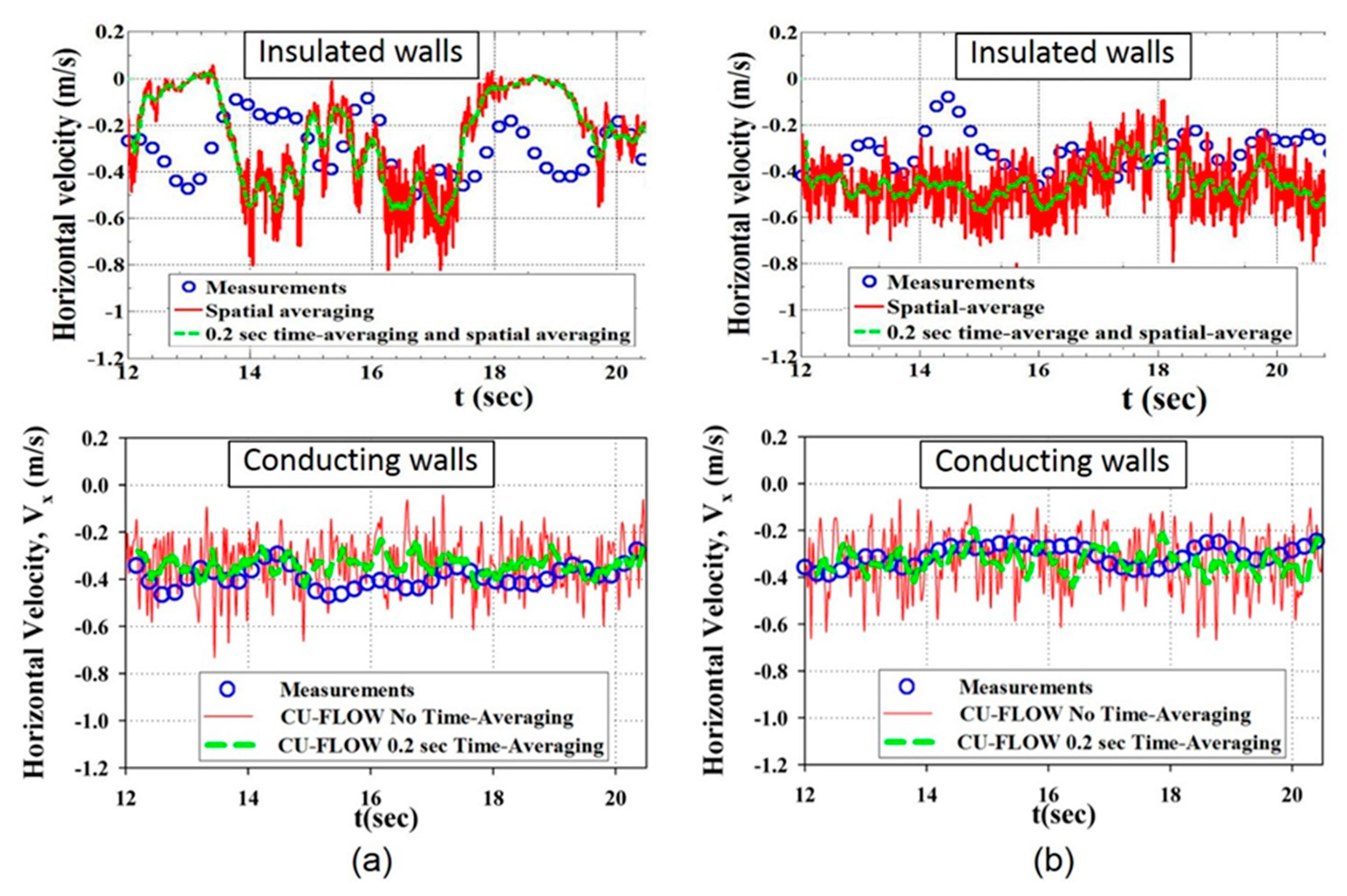
The effects of single-ruler EMBr also depend strongly on the location of the ruler [27,28]. Locating a single-ruler EMBr above the nozzle decreases surface level fluctuations, resulting in a more stable surface. On the other hand, lowering the magnetic field below the nozzle ports produces shallower downward jet angles, higher surface velocities, lower turbulent kinetic energy at the surface, and better surface flow stability, especially at higher level fluctuation frequencies. In addition, vortex formation at the mold top surface, caused by biased surface flow due to nozzle misalignment between left and right sides in the mold, can be lessened with single-ruler EMBr together with optimized argon injection [125]. Applying the ruler across nozzle ports worsens the flow instability, however, producing strong unbalanced, asymmetric transient behavior (jet wobbling) and complex flow [28,29,126], as shown in Figure 13. Thus, the electromagnetic field should not be placed with its maximum directly across the nozzle ports, where it may aggravate unstable flow. When modeling these phenomena, it is important to note that the flow instability with realistic conducting walls is much less than with insulated walls [27,28,127,128], as shown in Figure 13. With single-ruler EMBr below the nozzle and electrically-conducting walls, the low-frequency oscillations of the jet flow are suppressed and results in a stable double-roll flow pattern with surface velocity within the window of safe operation, for the conditions simulated [28].
Vertical single-ruler EMBr is predicted to reduce both surface velocity and level fluctuations, especially near the meniscus [111]. The strong magnetic field oriented vertically along near the narrow faces tends to brake the upward flow produced after jet impingement on the narrow faces. Deepening SEN depth and lowering nozzle port angles (more downward) should further lessen surface fluctuations [111].

4.2. Double-Ruler EMBr

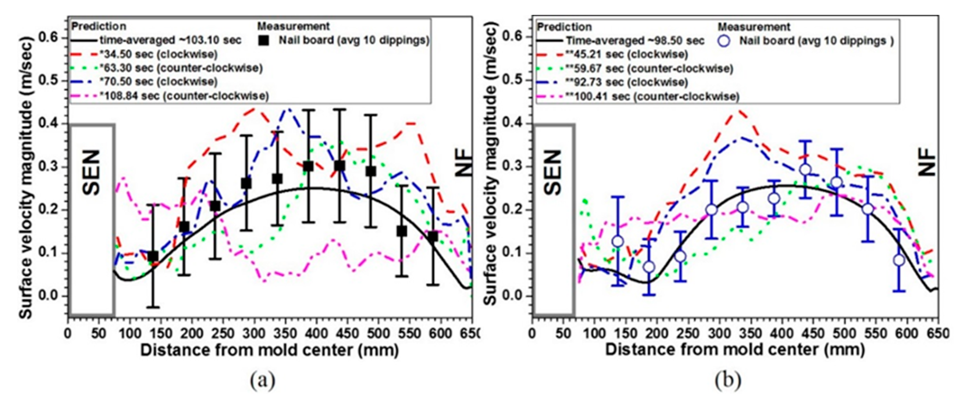
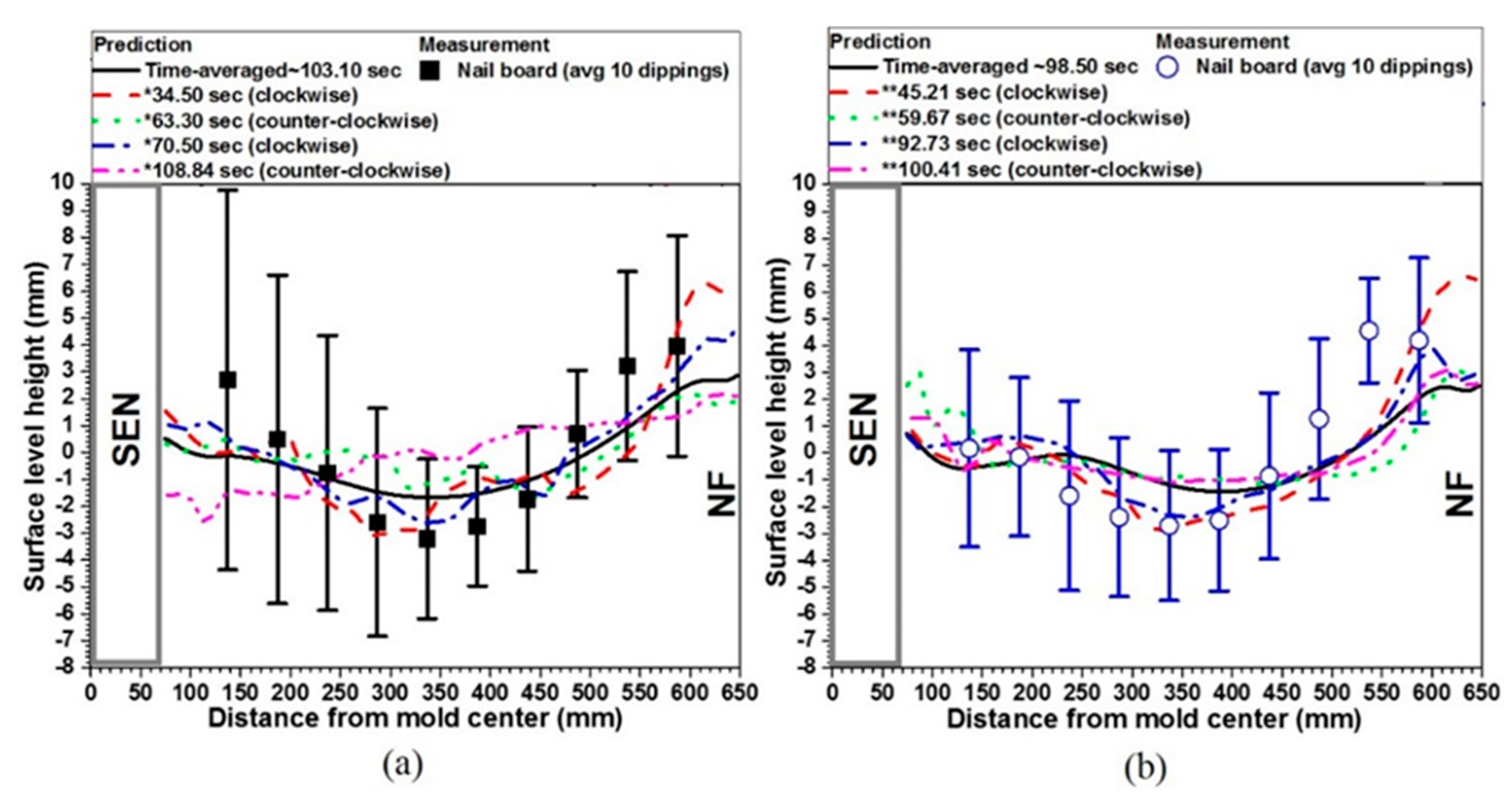
By surrounding the jets leaving the ports with static fields both above and below, double-ruler EMBr acts to stabilize the flow, deflecting chaotic turbulent variations in the jet direction back towards its designed path towards the narrow faces. Thus, asymmetrical flow and its associated variable surface defects tend to be reduced [79]. For example, surface level fluctuations caused by unbalanced flows in a slab mold are reduced with double-ruler EMBr [79]. Swirl flow inside the nozzle causes jet wobbling, especially with a slide-gate control system. This results in stronger variations in surface velocity and low-frequency level fluctuations [113], as shown in Figure 14a. The clockwise swirls, which have higher momentum than the counterclockwise swirls, due to shorter flowing path from the slide gate to the nozzle bottom on the right side in this orientation, produce higher surface velocity and surface level height. Thus, surface velocity and level fluctuation variations occur whenever the swirl flow direction changes in the nozzle bottom. Double-ruler EMBr reduces the surface velocity fluctuations due to the swirl direction changes as shown in Figure 14b, by dampening the momentum differences between swirl rotation directions. This is because the upper ruler field across the nozzle makes the velocity profile more uniform inside the nozzle [17,113], which then reduces jet wobbling and stabilizes the surface velocity and level across the mold width, as shown in Figure 15 and Figure 16 [113]. This effect is also likely with single-ruler EMBr above the nozzle ports.

4.3. Moving Fields: EMLS, EMLA, and EMRS

Moving field effects on flow stability in the mold region have received less previous study [39,51,56,75], compared to that of static fields. Feedback control systems have been implemented in a few commercial operations with EMLS and EMLA, adjusting the magnetic field strength according to the current “F-value” [105], which is an estimate of surface flow strength based on SEN geometry, mold width, and casting speed [51,75]. This system is reported to maintain stable surface level in the mold [51,75]. For this to be effective, the EMLS and EMLA fields should be located just below the nozzle ports [51,75] and the flow pattern should be double-roll [16]. It is especially important to avoid unstable flow due to continuous transition between single-roll and double-roll patterns, as shown in Figure 17, as this causes severe surface level fluctuations [16]. In addition, this system needs to be improved to handle argon gas [32].
As an alternative control method, the magnetic field strength could be adjusted more actively according to local flow conditions. Two feedback control systems, based on two sensor measurements of instantaneous surface level, are expected to be better. Flow rate from the stopper rod or slide gate can be controlled to maintain a constant average liquid level, based on the first sensor, located at the quarter point. This location, found midway between the SEN and NF, is the most stable location in the mold relative to the highest amplitude wave motion [60,64,113]. The other sensor can be located near the narrow-face meniscus. Then, the magnetic field strength can be controlled to decrease the estimated surface level profile variations, as indicated by the difference between the two sensor measurements [24].
Finally, EMRS appears not increase surface level fluctuations, even the magnetic field is located near the mold surface [51].

5. Electromagnetic Effects on Superheat Transport and Initial Solidification

Superheat is delivered with the molten steel flow towards top surface (mold flux layer), which affect initial solidification at the meniscus, and also deep into the mold cavity, which affects shell growth and potential thinning. Superheat transport depends on the mold flow pattern, which determines how the jet along with its superheat takes to reach different regions in the mold. The coldest regions tend to be found at the meniscus near the SEN and near the narrow faces. Stronger upward flow brings more superheat faster to these regions, resulting in higher meniscus temperatures. Optimal surface flow strength also mixes the liquid mold flux, which helps to melt the powder and encourage good gap infiltration and uniform lubrication. On the other hand, weaker upward flow results in a colder, stagnant meniscus, perhaps causing initial solidification problems including meniscus freezing, deeper oscillation marks and hooks, which can further increase particle capture, and slag infiltration problems. Thus, through its effect on the flow pattern, electromagnetic forces can also help to control superheat distribution, initial solidification, and shell growth.

5.1. Static Magnetic Fields

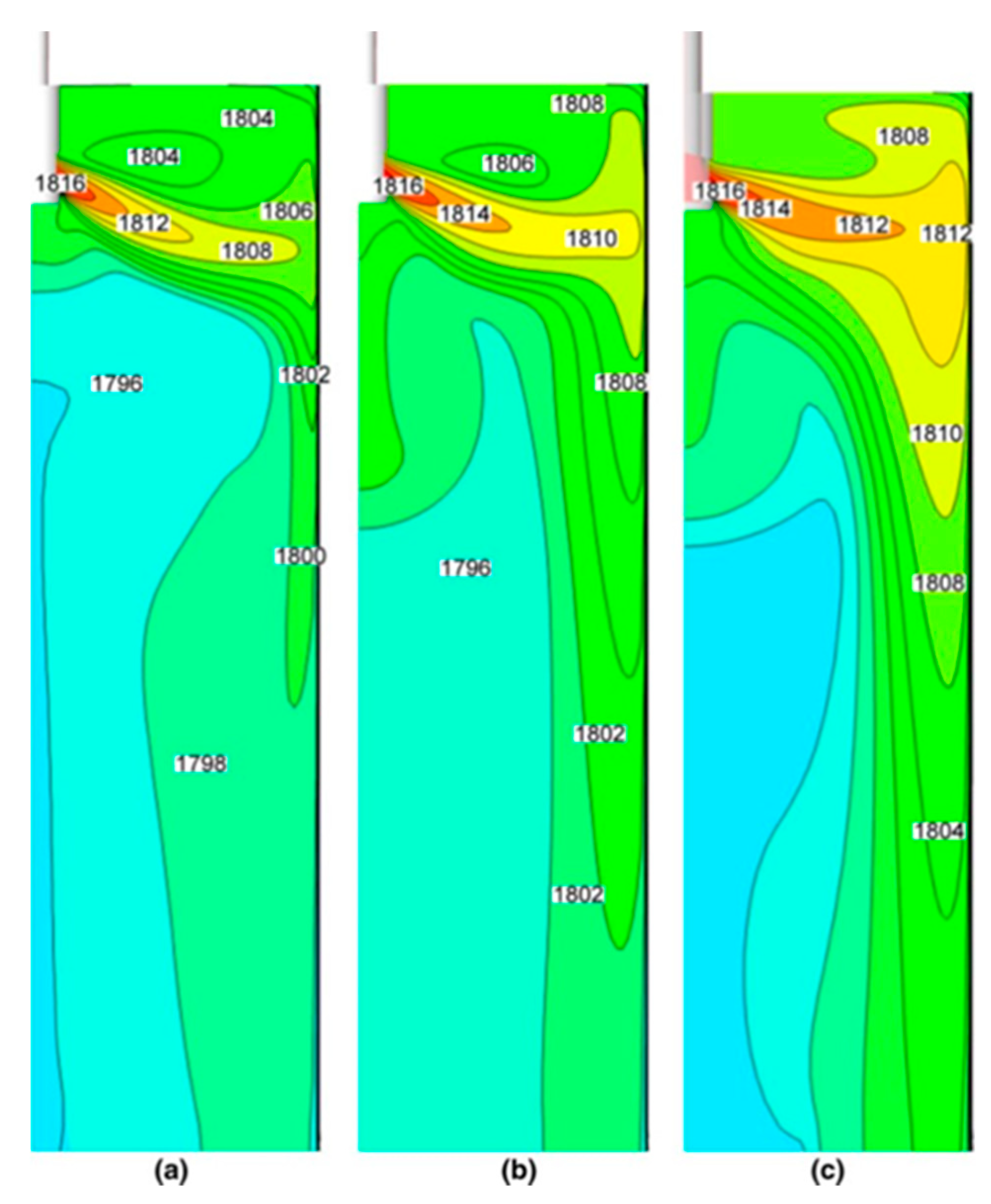
As discussed in Section 3.1 and Section 3.2, the location of static EMBr fields relative to the jet greatly affects the mold flow pattern. Thus, superheat transport is also influenced strongly by the magnetic field location [103,104,108,109,126,129,130]. Magnetic fields located below the jet deflect flow upwards towards the surface, leading to a hotter meniscus region [103,104], increasing meniscus temperature with increasing field strength, as shown in Figure 18 [104]. Optimal local EMBr fields can produce shallower oscillation marks [131].
On the other hand, magnetic fields above the jet deflect flow downwards, deeper into the mold cavity. The weaker upward flow transports less superheat to the mold upper mold, resulting in meniscus freezing, flow stagnation at the surface, and associated quality problems. In addition, local EMBr field can lessen jet intensity in the lower mold, resulting in a more uniform shell with less shell thinning at the jet impingement point [131].
Applying double-ruler EMBr has more flexibility to control the mold flow. Thus, superheat transport towards the stop surface is more adjustable by independent control of the field strengths of two rulers. More superheat is delivered towards the surface with stronger upward flows if the lower ruler is stronger and the upper ruler field is far above the nozzle ports [115,132]. This increases meniscus temperatures [115,132]. This can decrease the depths of oscillation marks and subsurface hooks, which are strongly related to low temperature distributions near the meniscus [100,101], as shown in Figure 19 [132]. Alternatively, abnormally high strength or low location of the upper ruler field can make the meniscus flow stagnant, causing associated surface defects.

5.2. Horizontally-moving Magnetic Fields: EMRS, M-EMS, and EMLA

The horizontally-rotating magnetic fields applied with EMRS or M-EMS produce rotating flow around the perimeter of the mold. This makes superheat transport and temperature distribution more uniform near the solidifying steel shell, especially where the meniscus tends to be cold, near the SEN and narrow faces [34]. Thus, depths of hooks and oscillation marks should be lessened. This also enables improvement of heat transfer uniformity through the slag layer in the steel shell/mold gap around the mold. Thus, the initial steel solidification around the mold is more uniform [34]. Uniformity of initial solidification can lessen defects such as longitudinal cracks, which initiate at local nonuniformities where stress can concentrate.
EMLA can increase temperature near the meniscus, by strengthening the upper flow along with delivering more superheat to the upper region of mold [32]. This is expected to have similar benefits of shallower oscillation marks and hooks.

5.3. Vertically Rotating Field near Meniscus: EMC

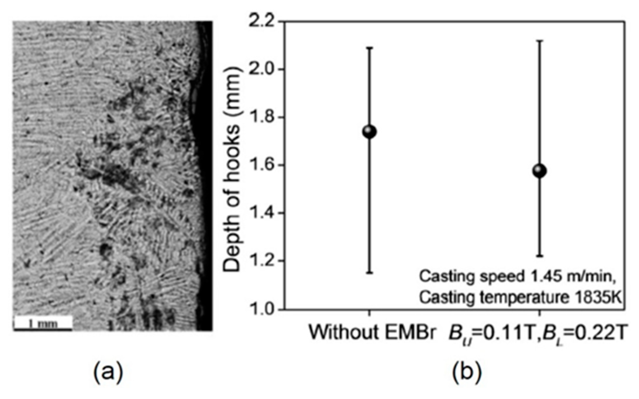
The moving EMC fields near the meniscus create two vertically counter-rotating recirculation zones near the meniscus [36,38]. The lower flow recirculation opposes molten steel trying to overflow the meniscus during each mold oscillation cycle. It also mixes the local superheat making temperature near the meniscus more uniform. These effects reduce oscillation mark depth and hook formation [36,38] as shown in Figure 20. This is expected to improve surface quality and to reduce particle capture defects.

6. Electromagnetic Effects on Particle Transport and Capture

Particles including bubbles, alumina, and slag inclusions may be transported with the flow and removed to the surface slag layer, or captured into the solidifying steel shell. Large particles are detrimental to product properties such as fatigue life, especially in high-strength steel. Bubbles are detrimental because they are usually coated with small inclusions. Captured large bubbles concentrate the inclusions into large clusters, so are detrimental to final steel product quality if they cannot be removed by further processes such as surface scarfing. Large particles are also detrimental by leading to delaminations, blisters, pencil pipes, and other defects during downstream operations [133,134].
Near the meniscus, excessive surface flow causes surface profile variations and level fluctuations, which can entrain slag as inclusions into the molten steel pool, and/or may directly entrap slag, inclusions, and bubbles into the steel shell at the meniscus [8,74]. In addition, single-roll surface flows towards narrow faces or cross-surface flows between wide faces may move particles trapped at the interface between the liquid mold slag and the molten steel pool, to the meniscus regions, where they may be captured. Alternatively, strong flow across (tangential to) the steel solidification front can wash particles away from the solidifying steel shell front, resulting in less particle capture [82,94].
Abnormally slow surface flow can lead to insufficient superheat transport to the meniscus, leading to deeper frozen hooks, as discussed in Section 5. This can cause more particle capture defects in the mold regions. Thus, the first objective of flow control is to maintain surface flows in a safe window of operation. Electromagnetic fields, combined with other casting conditions and nozzle geometry, can help to achieve this. The extra control possible with electromagnetics, however, may enable paying attention to particle transport and capture independent from surface flow.
Finally, electromagnetic fields can change the local velocity field adjacent to non-conducting particles, such as large argon bubbles, which can change the bubble shape and terminal rising velocity, relative to the flow field [135]. Thus, electromagnetic effects on the flow pattern and turbulence can significantly affect particle transport and the fraction and distributions of entrapped particles in several ways.

6.1. Local and Single-Ruler EMBr

As discussed in Section 3, Section 4 and Section 5, with local or single-ruler EMBr field located below the jets, the jets deflect upward towards the mold top surface, which could help argon bubbles and other particles carried with the flow to escape into the surface slag layer [104]. However, excessive upward flow may disrupt the top surface and allow more bubbles to accumulate beneath the slag layer, especially near the SEN, where they may be captured during initial solidification. In extreme cases, strong surface flows, such as caused by a poorly-designed local field, can push the liquid mold flux away, causing an open eye, where the molten steel is exposed to the powder and air [136]. This must be avoided because the associated reoxidation, contamination with carbon from the mold powder, bubble, and slag entrainment are all very detrimental to steel quality. Thus, the main objective of EMBr is to change the flow pattern to avoid excessive surface-directed flows to avoid particle entrapment and other defects associated with excessive surface flows.
On the other hand, if EMBr fields are located partly above the nozzle ports, so the jets are deflected downward, the flow may transport more particles deep into the strand below the mold. This will increase internal defects, as only a small fraction (lower than ~10%) of these particles are able to return to the top slag layer [137]. Thus, placing local or single-ruler EMBr fields at a proper location is important to control particle transport and capture in the mold, as expected from the effects on fluid flow pattern and surface instability, discussed in previous Section 3.1, Section 3.2 and Section 4.1.

6.2. Double-Ruler EMBr

The upper ruler of double-ruler EMBr can help to avoid excessive surface flows and stabilizes the surface slag/molten steel interface in the mold, which tends to reduce the entrapment of inclusions due to level fluctuations [113]. These effects are similar to a single-ruler EMBr above the nozzle.
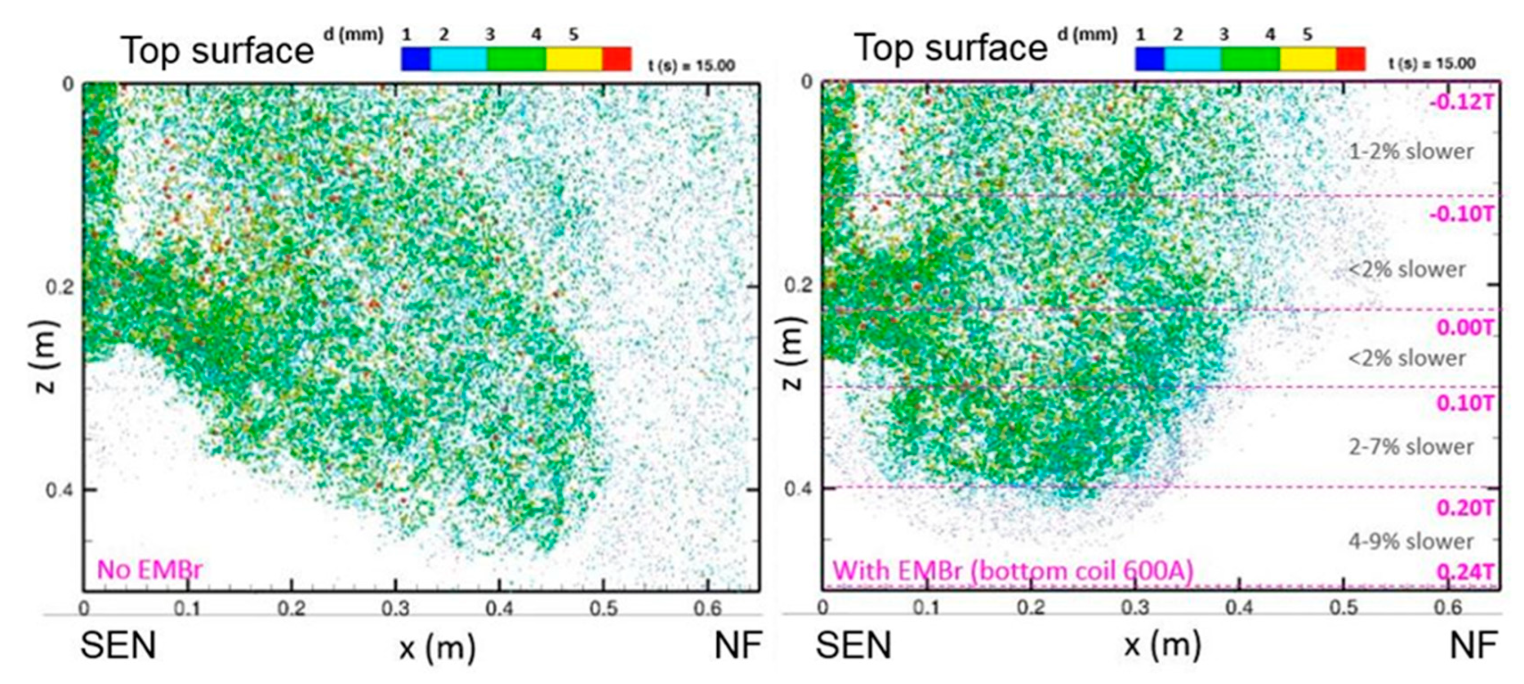
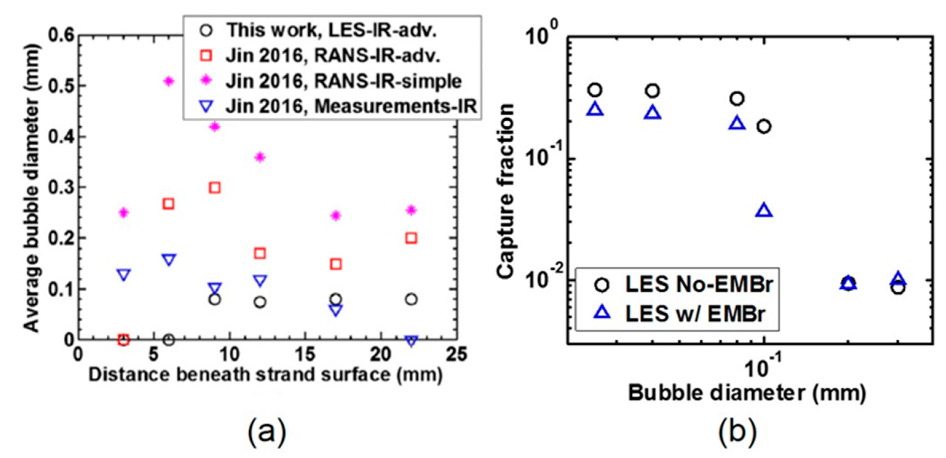
The lower ruler of double-ruler EMBr can help to lessen jet penetration and particle transport deep into the strand. As shown in Figure 21 [138], such an EMBr system causes fewer bubbles to be transported towards the narrow faces. The sizes and fractions of bubbles captured with these two flow patterns are shown in Figure 22 [138]. Small particles which contact the solidification front are easily entrapped between dendrites. On the other hand, large particles are only captured if the particle stays at the solidification front for long enough time to become surrounded by the growing shell front [82,94,138,139,140]. A simple criterion, which captures any particle touching the solidifying shell, overpredicts the capture of large particles, as shown in Figure 22a. Calculations with an advanced capture criterion [82,94,138] consider a potential balance of eight forces on the particle at the shell front, which include the drag from tangential velocities, which can wash away the particles from the solidification front, back into the main flow. This sophisticated capture model agrees better with plant measurements in Figure 22a, which show an average bubble diameter of ~0.1mm. Results also show that the average size of bubbles captured near the meniscus is slightly bigger than those captured deeper in the caster. Meniscus hooks, not included in the model, likely capture larger particles rising up beneath them. The change in the bubble transport with double-ruler EMBr tends to decrease the fraction of bubbles captured into the solidifying steel, as shown in Figure 22b, especially the 0.1mm size [82,138]. In addition, less deep hooks, due to more superheat towards the meniscus region with double-ruler EMBr, can reduce inclusion capture into the hooks [132] as shown in Figure 23.
However, bubbles can penetrate deeper into the mold with double-ruler EMBr if the lower-ruler field strength is not enough to reduce the downward flow velocity near the narrow faces [113]. On the other hand, excessive strength of the upper ruler field can make the surface flow stagnant, leading to formation of more hooks which can entrap more slag inclusions into the shell. Thereby, optimizing the strength of both rulers is important to reduce the particle transport and capture [79,115,138], improving both surface and internal quality of the steel slabs.

6.3. Moving Magnetic Fields

Proper application of EMLS magnetic fields to stabilize surface velocity and surface level fluctuations may also help to reduce particle-related defects in the final steel product [32]. This is due to lessening the entrainment of slag inclusions and bubbles coated with inclusions and their capture into the solidifying steel shell, especially at the meniscus, as discussed in the previous section.
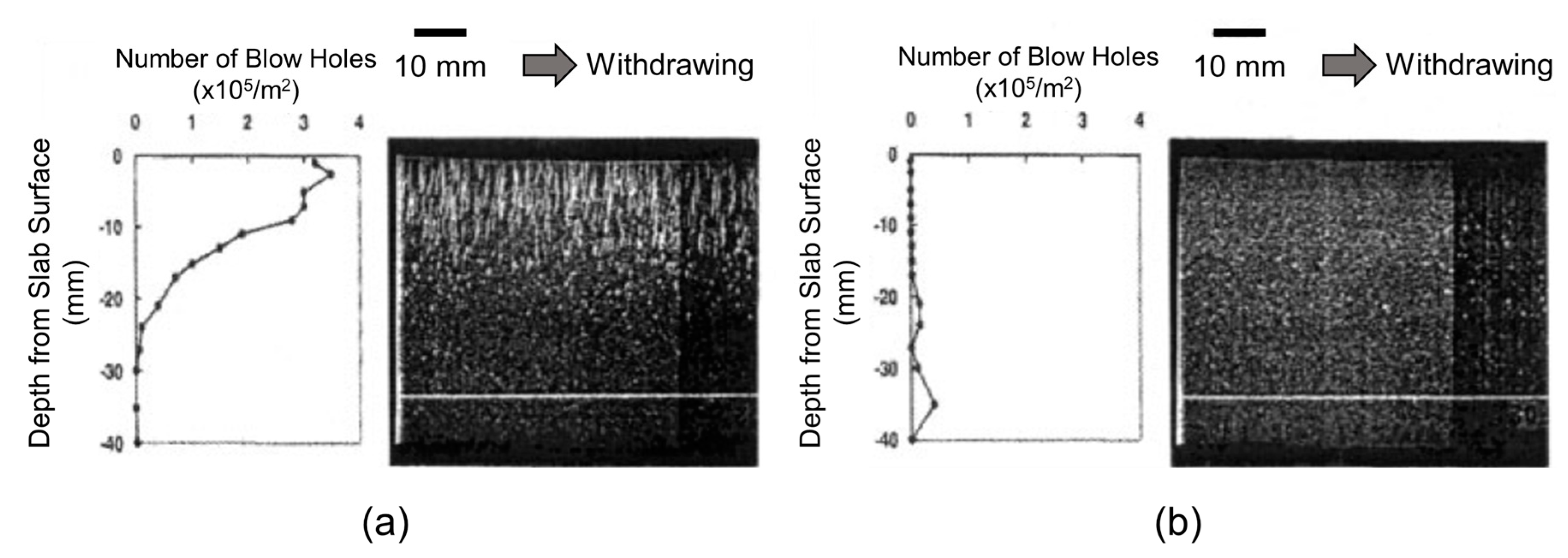
Horizontally-rotating magnetic fields induced by EMRS or M-EMS produce horizontally-rotating flow patterns around the perimeter of the mold. This flow pattern can wash away particles from the steel shell front in the mold [32,34,124,141,142,143], especially near the meniscus region, and from beneath subsurface hooks. This can significantly reduce defects related to the capture of bubbles near the surface (sometimes called pinholes or blowholes) [32,34], as shown in Figure 24, and other defects with large inclusions (slag, alumina [34], or calcium-alumina). In addition, more uniform surface temperature near the meniscus can lessen hook depth as discussed in Section 5. This in turn can reduce particle capture at the meniscus. Both the washing effect and the reduction of hooks are effective to reduce particle capture defects. Similar washing effects to lessen the capture of large inclusions might be involved with EMLA, and/or SEMS, but this needs further investigation, as previous work could not be found.

7. Electromagnetic Effects on Grain Structure and Internal Quality

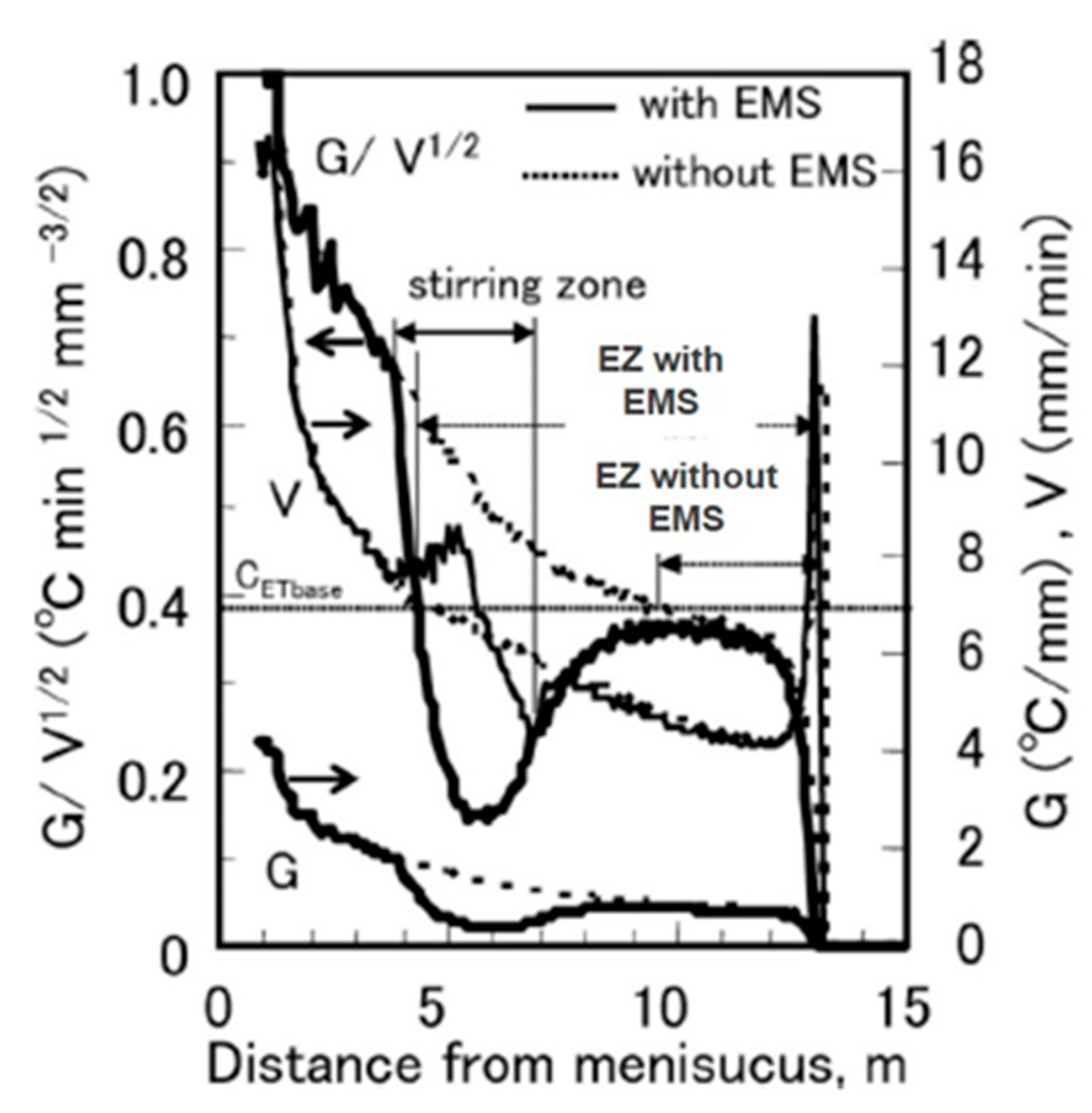
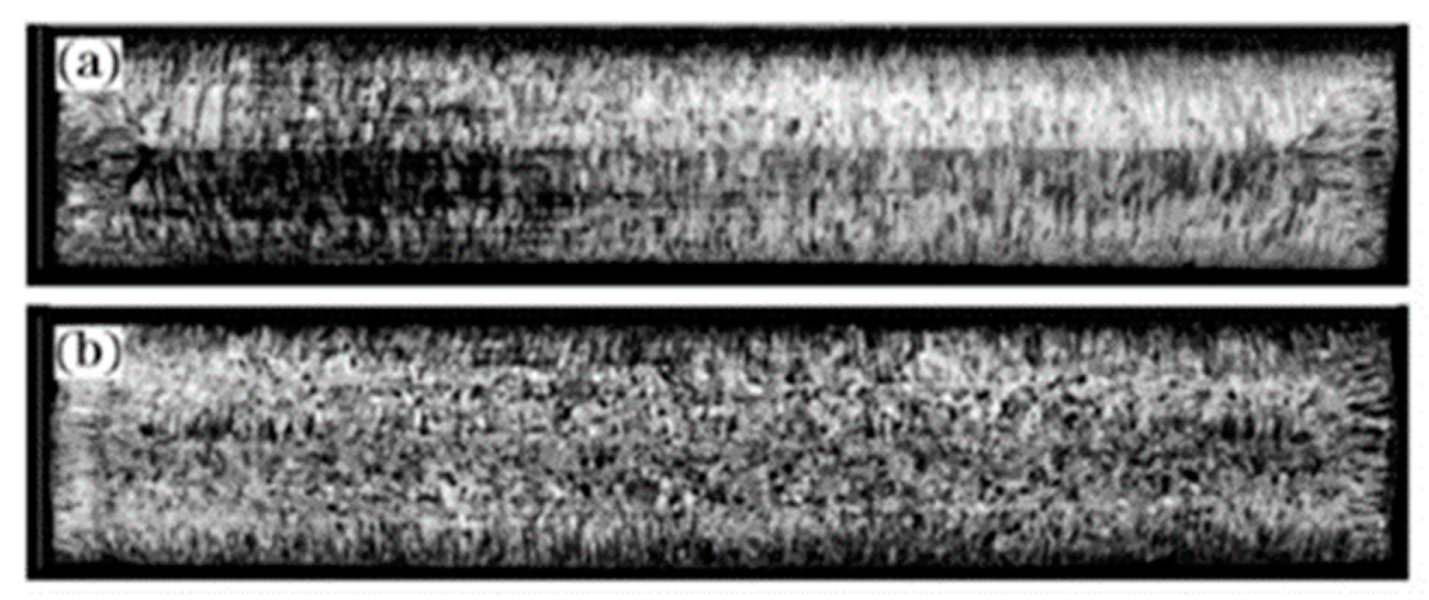
Grain structure including the chill zone, columnar zone, Columnar-Equiaxed Transition (CET), and equiaxed zone is important for steel mechanical properties. Having more equiaxed grains in the slab correlates with less center segregation [144]. Many efforts have been made to increase the equiaxed zone size using electromagnetics. M-EMS can increase nuclei formation, resulting in smaller grains near the strand surface [34], perhaps due to the higher velocity flow across the solidification front melting off dendrite tips [145]. If more nuclei can survive and flow deep into the molten steel pool, this would be expected to lead to a larger fraction of equiaxed grains in the final product. Similarly, SEMS induces rotating flow below the mold, specifically in the vertical plane of the width and casting directions [33,40,42,45], which should decrease temperature gradients in the liquid, and has been shown to increase the size of the central equiaxed zone [33,40,42,45,146], as shown in Figure 25. In nonoriented electrical steel casting, the application of two sets of two pairs of in-roll SEMS magnetic fields at 400 A and 5 Hz was reported to show great improvement of grain structure, to over 60% equiaxed, as shown in Figure 26 [42].
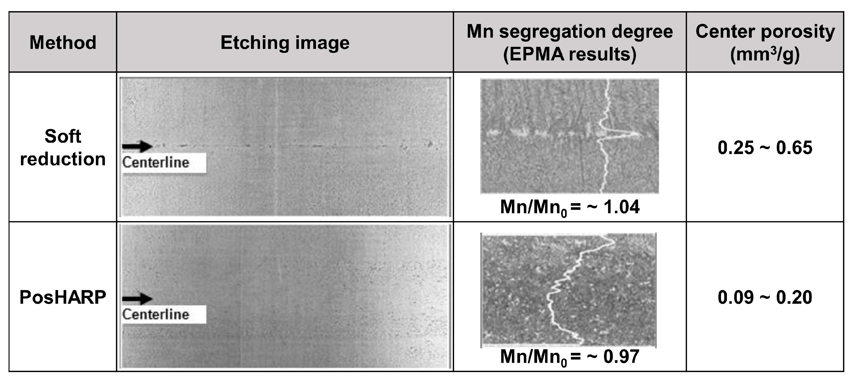
In addition, strand EMS also affects segregation and centerline quality. Applying S-EMS together with soft reduction (Posco Heavy strAnd Reduction Process: PosHARP) has been reported to reduce center porosity and centerline segregation (abnormal high and varying solute concentration between the dendrites near final solidification) better than soft reduction alone [43], as shown in Figure 27.
However, white bands (low solute concentration) and/or dark bands (high solute concentration) in the steel microstructure are caused by tangential flow across the solidification front, due to nonuniform solute distribution in the strand region. These distinctive bands of macrosegregation can be seen in slabs cast with SEMS, always at the depth into the slab where the flow was induced [147], such as in Figure 26b. In addition, distinctive changes in the angle of the columnar dendrite growth directions can be seen in the cross-sections of slabs cast with SEMS, corresponding with the changing flow directions across the solidification front with distance down the strand. The effect of casting conditions and flow control methods with and without electromagnetic effects on segregation and grain structure needs more study to more accurately quantify the relation between fluid flow, macrosegregation, grain structure, and related steel quality.

8. Electromagnetic Control of Steel Composition Distribution: Clad Steel Casting

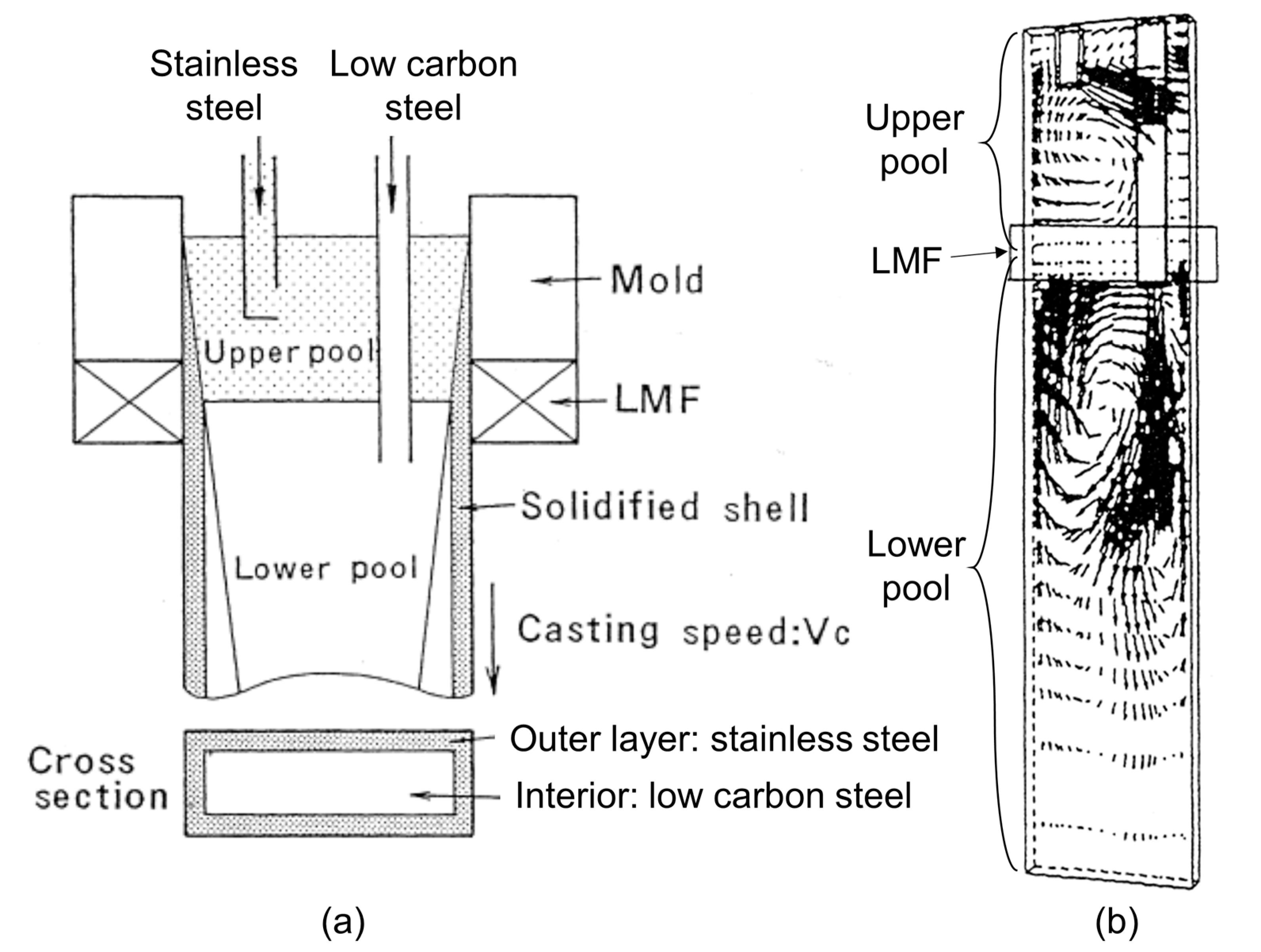
Another type of horizontal rectangular-shaped static magnetic field with a single-ruler, also called Level DC Magnetic Field (LMF) [30], is useful to manufacture clad steel slabs. This strong static field is employed across the slab mold in between the submergence depths of two nozzles, which deliver two different steel grades into the mold, as shown in Figure 28a. This magnetic field applied just below the mold exit produces two separated flow zones in the upper and lower pools, as shown in Figure 28b. This tends to lessen mixing of the two steel alloys, which consist of a stainless steel surface layer, which solidifies first, and a low carbon steel interior that solidifies later below the mold.
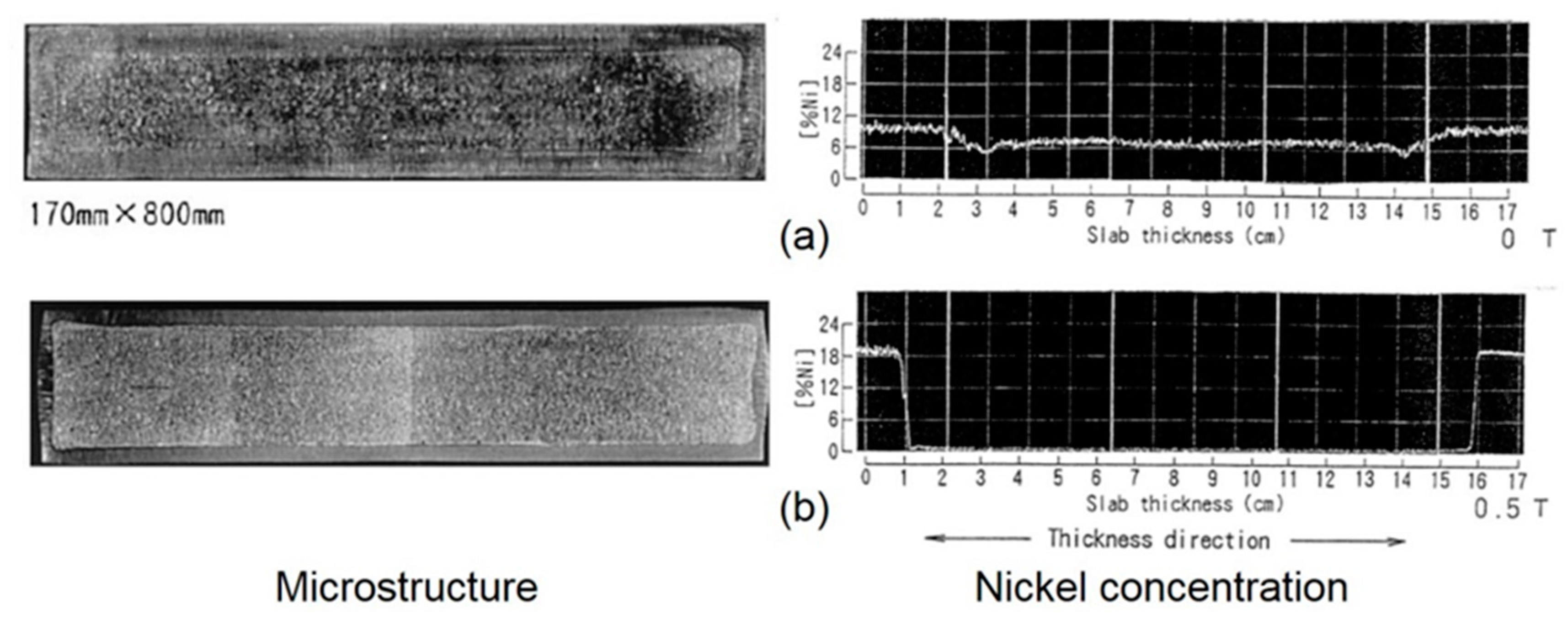
Figure 29 shows the effects of LMF on microstructure and composition distribution in the clad steel slab. With LMF, the sharp gradient in nickel concentration at the interface between the stainless steel (outer surface layer) and the low carbon steel (interior) and the negligible nickel in the interior both indicate the effectiveness of LMF to prevent mixing of stainless steel into the interior.

9. Summary and Conclusions

This paper has reviewed the many different types of electromagnetic systems used in slab casting to affect fluid flow and related phenomena and the research tools that can be used to investigate and understand the phenomena that affect steel product quality. Some of these effects and practical strategies to operate these electromagnetic systems are summarized below.
  • Combining several plant measurement methods is recommended to quantify the flow fluid and effects on quality, owing to the complexity of the continuous casting process with electromagnetics and the difficulty of making direct measurements.
  • Computational modeling validated with plant measurements and lab experiments is the best way to quantify and understand the effects of electromagnetic forces on fluid flow, superheat transfer, solidification, particle transport and capture, grain structure, steel composition, and other phenomena and defects.
  • Static magnetic fields (local, single-ruler, and double-ruler EMBr and EMB), moving magnetic fields (EMLS, EMLA, EMRS/M-EMS, EMC, and SEMS), and combined systems have been developed to affect the flow pattern and flow stability, aiming to control the intensity of surface flows in the mold to reduce various defects including surface defects, slag entrainment, inclusion entrapment, and deep oscillation marks, and/or to control internal cleanliness, grain structure, segregation, and porosity.
  • EMBr, EMB, EMLS, and EMLA are designed to maintain a stable double-roll flow pattern which keeps surface velocity, profile, and level fluctuations within a safe operating window, which is most useful for higher casting speed operations, especially thin-slab casting.
  • Placing static EMBr fields at a proper location relative to the flowing jets is critical to achieving the flow objectives. A strong magnetic field above the jet core tends to deflect the jets downward, and to slow surface velocity, which decreases variations in surface level and profile. In this case, care is needed to avoid over cooling the surface if the field is too strong.
  • On the other hand, a strong magnetic field below the jet core tends to deflect the jets upwards, increasing surface velocities when casting at low speed and lessening deep penetration of inclusions. In this case, care is needed to avoid upward excessive surface flows, if the field is too strong.
  • Locating the core of an EMBr magnetic field directly across the jets exiting the nozzle ports should be avoided to prevent unstable jet flow and associated defects.
  • A static ruler EMBr field across the nozzle above the ports helps to stabilize flow inside the nozzle, with consequent improvement of flow stability in the mold.
  • Maintaining proper ruler-EMBr field strength across the mold towards the narrow faces is important to reduce surface level fluctuations near the meniscus and jet penetration deep into the mold cavity.
  • Moving magnetic fields in the mold (EMLS, EMLA, EMRS, and M-EMS) actively drive the flow, providing an alternative method to achieve flow objectives. These include: EMLS moving fields towards the SEN, aiming to lower surface velocity and turbulence; EMLA moving fields towards the narrow faces, aiming to increase surface velocity and turbulence; and EMRS (M-EMS) fields rotating around the perimeter of the mold surface, aiming (in part) to wash particles away from the solidifying steel shell to lessen particle capture.
  • Superheat transport and initial solidification depend greatly on the mold flow pattern. Thus, adjusting the magnetic fields to deflect (static fields) or accelerate (EMLA) the jet upwards towards the top surface in the mold can reduce meniscus freezing, hook formation, and oscillation mark depth. Furthermore, rotating magnetic fields generated by EMRS (M-EMS), or EMC can make superheat and temperature near the meniscus more uniform.
  • Lessening the jet impingement depth, with a uniform ruler EMBr field across the mold below the jet, can reduce particle capture deep into the solidifying steel shell. In addition, the washing effect generated by a rotating flow pattern with EMRS or M-EMS can reduce surface defects including particle capture during initial solidification at the meniscus including subsurface hooks.
  • Below the mold, horizontally-moving fields towards one narrow face (SEMS) produces vertically rotating flows in the strand region, which mixes superheat, resulting in increased equiaxed grains, and less center segregation and porosity defects.
  • Strong static magnetic fields can enable clad steel casting, by helping to separate two steel alloys without mixing, by generating two separate flow recirculation zones above and below the magnetic field.
  • The application of combined fields, employing a traveling field either horizontally (via EMRS or M-EMS) or vertically (EMC) in the upper part of the mold and a static field (single-ruler EMBr) in the lower part of a mold, has great potential to reduce both surface and internal defects: The horizontally-moving field around the perimeter of the mold surface can wash away particles at the solidifying steel shell front and prevent their capture. At the same time, the static field prevents the jet flow go deep into the mold cavity, thereby reducing particle penetration, capture, and internal defects.
  • The vertically moving EMC field near the meniscus can greatly reduce oscillation mark and hook depth.
  • One of the greatest benefits of electromagnetics over conventional flow control devices, (such as port geometry) is the potential to adjust the field strength during operation according to the current flow conditions. Even better is the potential to adjust the magnetic field according to real-time feedback from in-mold sensors, such as multiple sensors of surface level, in order to maintain the intensity of surface flows in window of safe operation real time. More work is needed to implement this into practice.
Electromagnetic systems have been designed to prevent defect formation and to improve steel quality. However, all of the process geometry and conditions including nozzle port angle, SEN depth, casting speed, and argon gas flow rate need to be considered together to find optimal flow system operation conditions including electromagnetics for a specific caster, according to its needs regarding steel quality concerns.

Author Contributions

S.-M.C. and B.G.T. reviewed the references and wrote the article. Furthermore, B.G.T. as a corresponding author supervised the paper preparation.

Funding

Support from the Continuous Casting Center at Colorado School of Mines, the Continuous Casting Consortium at University of Illinois at Urbana-Champaign, and the National Science Foundation GOALI grant (Grant No. CMMI 18-08731) are gratefully acknowledged.

Acknowledgments

Provision of FLUENT licenses through the ANSYS Inc. academic partnership program is much appreciated.

Conflicts of Interest

The authors declare no conflicts of interest.

References

  1. World Steel Association. Table 4. Production of Continuously Cast Steel. In Steel Statistical Yearbook 2018; World Steel Association: Brussels, Belgium, 2018; pp. 9–12. [Google Scholar]
  2. Thomas, B.G. Chapter 14. Fluid Flow in the Mold. In Making, Shaping and Treating of Steel, 11th ed.; Cramb, A., Ed.; Casting Volume; AISE Steel Foundation: Pittsburgh, PA, USA, 2003; Volume 5, pp. 14.1–14.41. [Google Scholar]
  3. Thomas, B.G. Chapter 15. Continuous Casting of Steel. In Modeling for Casting and Solidification Processing; Yu, O., Ed.; Marcel Dekker: New York, NY, USA, 2001; pp. 499–540. [Google Scholar]
  4. Thomas, B.G. Modeling of Continuous Casting Defects Related to Mold Fluid Flow. Iron Steel Technol. 2006, 3, 128–143. [Google Scholar]
  5. Najjar, F.M.; Thomas, B.G.; Hershey, D.E. Numerical Study of Steady Turbulent Flow through Bifurcated Nozzles in Continuous Casting. Metall. Mater. Trans. B 1995, 26B, 749–765. [Google Scholar] [CrossRef]
  6. Calderon-Ramos, I.; Morales, R.D.; Salazar-Campoy, M. Modeling Flow Turbulence in a Continuous Casting Slab Mold Comparing the use of Two Bifurcated Nozzles with Square and Circular Ports. Steel Res. Int. 2015, 86, 1610–1621. [Google Scholar] [CrossRef]
  7. Salazar-Campoy, M.M.; Morales, R.D.; Najera-Bastida, A.; Calderon-Ramos, I.; Cedillo-Hernandez, V.; Delgado-Pureco, J.C. A Physical Model to Study the Effects of Nozzle Design on Dispersed Two-Phase Flows in a Slab Mold Casting Ultra-Low-Carbon Steels. Metall. Mater. Trans. B 2018, 49B, 812–830. [Google Scholar] [CrossRef]
  8. Cho, S.-M.; Thomas, B.G.; Kim, S.-H. Effect of Nozzle Port Angle on Transient Flow and Surface Slag Behavior during Continuous Steel slab casting. Metall. Mater. Trans. B 2018, 50B, 52–76. [Google Scholar] [CrossRef]
  9. Thomas, B.G.; Mika, L.J.; Najjar, F.M. Simulation of Fluid Flow inside a Continuous Slab-Casting Machine. Metall. Mater. Trans. B 1990, 21B, 387–400. [Google Scholar] [CrossRef]
  10. Cho, S.-M.; Thomas, B.G.; Lee, H.-J.; Kim, S.-H. Effect of Nozzle Port Angle on Mold Surface Flow in Steel Slab Casting. Iron Steel Technol. 2017, 14, 76–84. [Google Scholar]
  11. Chaudhary, R.; Lee, G.-G.; Thomas, B.G.; Kim, S.-H. Transient Mold Fluid Flow with Well- and Mountain-Bottom Nozzles in Continuous Casting of Steel. Metall. Mater. Trans. B 2008, 39B, 870–884. [Google Scholar] [CrossRef]
  12. Gursoy, K.A.; Yavuz, M.M. Effect of Flow Rate Controllers and their Opening Levels on Liquid Steel Flow in Continuous Casting Mold. ISIJ Int. 2016, 56, 554–563. [Google Scholar] [CrossRef] [Green Version]
  13. Wang, Y.; Zhang, L. Transient Fluid Flow Phenomena during Continuous Casting: Part II—Cast Speed Change, Temperature Fluctuation, and Steel Grade Mixing. ISIJ Int. 2010, 50, 1783–1791. [Google Scholar] [CrossRef] [Green Version]
  14. Bai, H.; Thomas, B.G. Turbulent Flow of Liquid Steel and Argon Bubbles in Slide gate Tundish Nozzles: Part II. Effect of Operation Conditions and Nozzle Design. Metall. Mater. Trans. B 2001, 32B, 269–284. [Google Scholar] [CrossRef]
  15. Liu, Z.Q.; Qi, F.S.; Li, B.K.; Cheung, S.C.P. Modeling of bubble behaviors and size distribution in a slab continuous casting mold. Int. J. Multiphase Flow 2016, 79, 190–201. [Google Scholar] [CrossRef]
  16. Dauby, P.H. Continuous casting: Make better steel and more of it! Revue de Métallurgie 2012, 109, 113–136. [Google Scholar] [CrossRef]
  17. Jin, K.; Vanka, S.P.; Thomas, B.G. Large Eddy Simulations of the Effects of EMBr and SEN Submergence Depth on Turbulent Flow in the Mold Region of a Steel Caster. Metall. Mater. Trans. B 2017, 48B, 162–178. [Google Scholar] [CrossRef]
  18. Jacobi, H.F. Investigation of Centreline Segregation and Centreline Porosity in CC-Slabs. Steel Res. Int. 2003, 74, 667–678. [Google Scholar] [CrossRef]
  19. El-Bealy, M.O. Macrosegregation Quality Criteria and Mechanical Soft Reduction for Central Quality Problems in Continuous Casting of Steel. Mater. Sci. Appl. 2014, 5, 724–744. [Google Scholar] [CrossRef]
  20. Thomas, B.G. Review on Modeling and Simulation of Continuous Casting. Steel Res. Int. 2018, 89, 1700312. [Google Scholar] [CrossRef]
  21. Thomas, B.G. Chapter 5. Modeling of Continuous Casting. In Making, Shaping and Treating of Steel, 11th ed.; Cramb, A., Ed.; Casting Volume; AISE Steel Foundation: Pittsburgh, PA, USA, 2003; Volume 5, pp. 5.1–5.24. [Google Scholar]
  22. Thomas, B.G.; Zhang, L. Mathematical Modeling of Fluid Flow in Continuous Casting. ISIJ Int. 2001, 41, 1181–1193. [Google Scholar] [CrossRef]
  23. Yuan, Q.; Zhao, B.; Vanka, S.P.; Thomas, B.G. Study of Computational Issues in Simulation of Transient Flow in Continuous Casting. Steel Res. Int. 2005, 76, 33–43. [Google Scholar] [CrossRef]
  24. Kollberg, S.; Lofgren, P.M.; Hanley, P. Improving Quality and Productivity in Thick Slab Casting by Direct Control of ElectroMagnetic Brake (EMBR). In Proceedings of the AISTech 2004, Nashville, TN, USA, 15–17 September 2004; pp. 977–984. [Google Scholar]
  25. Zeze, M.; Harada, H.; Takeuchi, E.; Ishii, T. Application of DC Magnetic Field for the Control of Flow in the Continuous Casting Strand. In Proceedings of the 76th Steelmaking Conference, Dallas, TX, USA, 28–31 March 1993; pp. 267–272. [Google Scholar]
  26. Qian, Z.-D.; Wu, Y.-L. Large Eddy Simulation of Turbulent Flow with the Effects of DC Magnetic Field and Vortex Brake Application in Continuous Casting. ISIJ Int. 2004, 44, 100–107. [Google Scholar] [CrossRef] [Green Version]
  27. Singh, R.; Thomas, B.G.; Vanka, S.P. Effects of a Magnetic Field on Turbulent Flow in the Mold Region of a Steel Caster. Metall. Mater. Trans. B 2013, 44B, 1201–1221. [Google Scholar] [CrossRef]
  28. Thomas, B.G.; Singh, R.; Vanka, S.P.; Timmel, K.; Eckert, S.; Gerbeth, G. Effect of Single-Ruler Electromagnetic Braking (EMBr) Location on Transient Flow in Continuous Casting. J. Manuf. Sci. Prod. 2015, 15, 93–104. [Google Scholar] [CrossRef]
  29. Chaudhary, R.; Thomas, B.; Vanka, S. Effect of Electromagnetic Ruler Braking (EMBr) on Transient Turbulent Flow in Continuous Slab Casting using Large Eddy Simulations. Metall. Mater. Trans. B 2012, 43, 532–553. [Google Scholar] [CrossRef] [Green Version]
  30. Harada, H.; Takeuchi, E.; Zeze, M.; Tanaka, H. MHD analysis in hydromagnetic casting process of clad steel slabs. Appl. Math. Modell. 1998, 22, 873–882. [Google Scholar] [CrossRef]
  31. Kunstreich, S. Recent developments of electromagnetic actuators for continuous casting of long and flat products. MILLENNIUM STEEL 2014, 57–63. [Google Scholar]
  32. Kunstreich, S.; Dauby, P.H. Effect of liquid steel flow pattern on slab quality and the need for dynamic electromagnetic control in the mold. Ironmak. Steelmak. 2005, 32, 80–86. [Google Scholar] [CrossRef]
  33. Kunstreich, S. Electromagnetic stirring for continuous casting-Part 2. Rev. Met. Paris. 2003, 100, 1043–1061. [Google Scholar] [CrossRef]
  34. Nakashima, J.; Fukuda, J.; Kiyose, A.; Kawase, T.; Ohtani, Y.; Doki, M. Improvement of Slab Surface Quality with In-mold Electromagnetic Stirring; Nippon Steel and Sumitomo Metal Corporation: Tokyo, Japan, 2002; pp. 61–67. [Google Scholar]
  35. Fujisaki, K. In-Mold Electromagnetic Stirring in Continuous Casting. IEEE TRANSACTIONS ON INDUSTRY APPLICATIONS 2001, 37, 1098–1104. [Google Scholar] [CrossRef]
  36. Tani, M.; Zeze, M.; Toh, T.; Tsunenari, K.; Umetsu, K.; Hayashi, K.; Tanaka, K.; Fukunaga, S. Electromagnetic Casting Technique for Slab Casting. Nippon Steel Technical Report 2013, 104, 62–68. [Google Scholar] [CrossRef]
  37. Cha, P.-R.; Hwang, Y.-S.; Nam, H.-S.; Chung, S.-H.; Yoo, J.-K. 3D Numerical Analysis on Electromagnetic and Fluid Dynamic Phenomena in a Soft Contact Electromagnetic Slab Caster. ISIJ Int. 1998, 38, 403–410. [Google Scholar] [CrossRef]
  38. Toh, T.; Takeuchi, E.; Hojo, M.; Kawai, H.; Matsumura, S. Electromagnetic Control of Initial Solidification in Continuous Casting of Steel by Low Frequency Alternating Magnetic Field. ISIJ Int. 1997, 37, 1112–1119. [Google Scholar] [CrossRef]
  39. Kubota, J.; Kubo, N.; Ishii, T.; Suzuki, M.; Aramaki, N.; Nishimachi, R. Steel Flow Control in Continuous Slab Caster Mold by Traveling Magnetic Field. NKK TECHNICAL REVIEW 2001, 85, 1–9. [Google Scholar]
  40. Kunstreich, S. Electromagnetic stirring for continuous casting-Part 1. Rev. Met. Paris. 2003, 100, 395–408. [Google Scholar] [CrossRef]
  41. Dubke, M.; Tacke, K.-H.; Spitzer, K.-H.; Schwerdtfeger, K. Flow fields in electromagnetic stirring of rectangular strands with linear inductors: Part I. theory and experiments with cold models. Metall. Trans. B. 1988, 19B, 581–593. [Google Scholar] [CrossRef]
  42. Gong, J.; Liu, H.-p.; Wang, X.-h.; Bao, Y.-p. Numerical Simulation of Electromagnetic Field and Flow Pattern in a Continuous Slab Caster with in roll-type Strand Electromagnetic Stirring. J. Iron Steel Res. Int. 2015, 22, 414–422. [Google Scholar] [CrossRef]
  43. Kim, G.H.; Kwon, S.H.; Won, Y.M.; Lee, C.H. Enhancement of slab internal quality by electromagnetic stirring of molten steel. In Proceedings of the 8th International Conference on Electromagnetic Processing of Materials (EPM 2015), Cannes, France, 12–16 October 2015. [Google Scholar]
  44. Kunstreich, S. Strand electromagnetic stirring (S-EMS) for thick slab casters: Box-type or In-roll stirrers? Millennium Steel 2008, 122–124. [Google Scholar]
  45. El-Kaddah, N.; Natarajan, T.T. Electromagnetic Stirring of Steel: Effect of Stirring Design on Mixing in Horizontal Electromagnetic Stirring of Steel Slabs. In Proceedings of the Second International Conference on CFD in the Mineral and Process Industries, Melbourne, Australia, 6–8 December 1999; pp. 339–344. [Google Scholar]
  46. Dubke, M.; Tacke, K.-H.; Spitzer, K.-H.; Schwerdtfeger, K. Flow fields in electromagnetic stirring of rectangular strands with linear inductors: Part II. Computation of flow fields in billets, blooms, and slabs of steel. Metall. Trans. B. 1988, 19B, 595–602. [Google Scholar] [CrossRef]
  47. Lambert, V.; Galpin, J.-M.; Hackl, H.R.; Jacobson, N.P. New Strong Strand Stirrer Boosting Quality for Ferritic Stainless Steel. Iron Steel Technol. 2008, 5, 71–79. [Google Scholar]
  48. Sedén, M.; Jacobson, N.; Lehman, A.; Eriksson, J.-E. Control of Flow Behavior by FC Mold G3 in Slab Casting Process. In Proceedings of the 8th European Continuous Casting Conference, Graz, Austria, 23–26 June 2014. [Google Scholar]
  49. Qian, Z.-D.; Wu, Y.-L.; Li, B.-W.; He, J.-C. Numerical Analysis of the Influences of Operational Parameters on the Fluid Flow in Mold with Hybrid Magnetic Fields. ISIJ Int. 2002, 42, 1259–1265. [Google Scholar] [CrossRef]
  50. Yavuz, M.M. The Effects of Electromagnetic Brake on Liquid Steel Flow in Thin Slab Caster. Steel Res. Int. 2011, 82, 809–818. [Google Scholar] [CrossRef]
  51. Domgin, J.-F.; Anderhuber, M.; Doncker, M.D.; Paepe, A.D. Optimization of an Electromagnetic Technology in ArcelorMittal Gent for Improving Products Quality in Steel Industry. J. Manuf. Sci. Prod. 2015, 15, 105–117. [Google Scholar] [CrossRef]
  52. Mizukami, H.; Hanao, M.; Hiraki, S.; Kawamoto, M.; Watanabe, T.; Hayashi, A.; Iguchi, M. Measurement of Meniscus Flow Velocity in High Speed Continuous Casting Mold. Tetsu-to-Hagane 2000, 86, 265–270. [Google Scholar] [CrossRef]
  53. Iguchi, M.; Terauchi, Y. Karman Vortex Probe for the Detection of Molten Metal Surface Flow in Low Velocity Range. ISIJ Int. 2002, 42, 939–943. [Google Scholar] [CrossRef]
  54. Iguchi, M.; Kawabata, H.; Ogura, T.; Hayashi, A.; Terauchi, Y. A New Probe for Directly Measuring Flow Velocity in a Continuous Casting Mold. ISIJ Int. 1996, 36, S190–S193. [Google Scholar] [CrossRef]
  55. Han, S.-W.; Cho, H.-J.; Jin, S.-Y.; Sedén, M.; Lee, I.-B.; Sohn, I. Effects of Simultaneous Static and Traveling Magnetic Fields on the Molten Steel Flow in a Continuous Casting Mold. Metall. Mater. Trans. B 2018, 49B, 2757–2769. [Google Scholar] [CrossRef]
  56. Kubota, J.; Kubo, N.; Suzuki, M.; Ishii, T.; Nishimachi, R.; Aramaki, N. Steel Flow Control with Travelling Magnetic Field for Slab Continuous Caster Mold. Tetsu-to-Hagane 2000, 86, 69–75. [Google Scholar] [CrossRef]
  57. Jin, K.; Vanka, S.P.; Thomas, B.G.; Ruan, X. Large Eddy Simulations of the Effects of Double-Ruler Electromagnetic Braking and Nozzle Submergence Depth on Molten Steel Flow in A Commercial Continuous Casting Mold. In Proceedings of the TMS Annual Meeting, CFD Modeling and Simulation in Materials Processing Symposium 2016, Nashville, TN, USA, 14–18 March 2016; pp. 159–166. [Google Scholar]
  58. Dauby, P.H.; Emling, W.H.; Sobolewski, R. Lubrication in the Mold: A Multiple Variable System. Ironmaker Steelmaker 1986, 13, 28–36. [Google Scholar]
  59. Mcdavid, R.M.; Thomas, B.G. Flow and Thermal Behavior of the Top Surface Flux/Powder Layers in Continuous Casting Molds. Metall. Mater. Trans. B 1996, 27B, 672–685. [Google Scholar] [CrossRef]
  60. Cho, S.-M.; Lee, H.-J.; Kim, S.-H.; Chaudhary, R.; Thomas, B.G.; Lee, D.-H.; Kim, Y.-J.; Choi, W.-R.; Kim, S.-K.; Kim, H.-S. Measurement of Transient Meniscus Flow in Steel Continuous Casters and Effect of Electromagnetic Braking. In Proceedings of the TMS Annual Meeting Symposium 2011, San Diego, CA, USA, 27 February–3 March 2011. [Google Scholar]
  61. Cukierski, K.; Thomas, B.G. Flow Control with Local Electromagnetic Braking in Continuous Casting of Steel Slabs. Metall. Mater. Trans. B 2008, 38B, 94–107. [Google Scholar] [CrossRef]
  62. Liu, R.; Thomas, B.G.; Sengupta, J.; Chung, S.D.; Trinh, M. Measurements of Molten Steel Surface Velocity and Effect of Stopper-rod Movement on Transient Multiphase Fluid Flow in Continuous Casting. ISIJ Int. 2014, 54, 2314–2323. [Google Scholar] [CrossRef] [Green Version]
  63. Rietow, B.; Thomas, B.G. Using Nail Board Experiments to Quantify Surface Velocity in the CC Mold. In Proceedings of the AISTech 2008, Pittsburgh, PA, USA, 5–8 May 2018; pp. 1–11. [Google Scholar]
  64. Cho, S.-M.; Kim, S.-H.; Thomas, B.G. Transient Fluid Flow during Steady Continuous Casting of Steel Slabs: Part I. Measurements and Modeling of Two-phase Flow. ISIJ Int. 2014, 54, 845–854. [Google Scholar] [CrossRef] [Green Version]
  65. Köhler, K.U.; Andrzejewski, P.; Julius, E.; Haubrich, H. Steel Flow Velocity Measurement and Flow Pattern Monitoring in the Mould. In Proceedings of the 78th Steelmaking Conference, Nashville, TN, USA, 2–5 April 1995; pp. 445–449. [Google Scholar]
  66. Thomas, B.G.; Yuan, Q.; Sivaraj Sivaramakrishnan, S.; Shi, T.; Vanka, S.P.; Assar, M.B. Comparison of Four Methods to Evaluate Fluid Velocities in a Continuous Slab Casting Mold. ISIJ Int. 2001, 41, 1262–1271. [Google Scholar] [CrossRef]
  67. Assar, M.; Dauby, P.H.; Lawson, G.D. Opening the Black Box: PIV and MFC Measurements in a Continuous Caster Mold. In Proceedings of the 83rd Steelmaking Conference, Pittsburgh, PA, USA, 26–29 March 2000. [Google Scholar]
  68. Okano, S.; Nishimura, T.; Ooi, H.; Chino, T. Relation between Large Inclusions and Growth Directions of Columnar Dendrites in Continuously Cast Slabs. Tetsu-to-Hagane 1975, 61, 2982–2990. [Google Scholar] [CrossRef] [Green Version]
  69. Esaka, H.; Toh, T.; Harada, H.; Takeuchi, E.; Fujisaki, K. Deflection of Steel Dendrite Growing in the Fluid Flow Driven by Electromagnetic Stirrer. Tetsu-to-Hagane 2000, 86, 247–251. [Google Scholar] [CrossRef] [Green Version]
  70. Wang, X.; Wang, S.; Zhang, L.; Sridhar, S.; Conejo, A.; Liu, X. Analysis on the Deflection Angle of Columnar Dendrites of Continuous Casting Steel Billets Under the Influence of Mold Electromagnetic Stirring. Metall. Mater. Trans. A 2016, 47A, 5496–5509. [Google Scholar] [CrossRef]
  71. Melissari, B.; Argyropoulos, S.A. Measurement of Magnitude and Direction of Velocity in High-Temperature Liquid Metals. Part I: Mathematical Modeling. Metall. Mater. Trans. B 2005, 36B, 691–700. [Google Scholar] [CrossRef]
  72. Melissari, B.; Argyropoulos, S.A. Measurement of Magnitude and Direction of Velocity in High-Temperature Liquid Metals. Part II: Experimental Measurements. Metall. Mater. Trans. B 2005, 36B, 639–649. [Google Scholar] [CrossRef]
  73. Argyropoulos, S.A. Measuring velocity in high-temperature liquid metals: A review. Scand. J. Metall. 2000, 30, 273–285. [Google Scholar] [CrossRef]
  74. Hibbeler, L.C.; Thomas, B.G. Mold Slag Entrainment Mechanisms in Continuous Casting Molds. Iron Steel Technol. 2013, 10, 121–134. [Google Scholar]
  75. Kubota, J.; Okitoto, K.; Shirayata, A.; Murakati, H. Meniscus Flow Control in the Mold by Traveling Magnetic Field for High Speed Slab Caster. In Proceedings of the 74th Steelmaking Conference, Washington, DC, USA, 14–17 April 1991; pp. 233–241. [Google Scholar]
  76. Akhtar, A.; Thomas, B.G.; Sengupta, J. Analysis of Nail Board Measurements of Liquid Slag Layer Depth. In Proceedings of the AISTech 2016, Pittsburgh, PA, USA, 16–19 May 2016; pp. 1427–1438. [Google Scholar]
  77. Yuan, Q.; Thomas, B.G.; Vanka, S.P. Study of Transient Flow and Particle Transport in Continuous Steel Caster Molds: Part I. Fluid Flow. Metall. Mater. Trans. B 2004, 35B, 685–702. [Google Scholar] [CrossRef]
  78. Zhang, L.; Thomas, B.G. State of the Art in Evaluation and Control of Steel Cleanliness. ISIJ Int. 2003, 43, 271–291. [Google Scholar] [CrossRef]
  79. Furumai, K.; Matsui, Y.; Murai, T.; Miki, Y. Evaluation of Defect Distribution in Continuously-Cast Slabs by Using Ultrasonic Defect Detection System and Effect of Electromagnetic Brake on Decreasing Unbalanced Flow in Mold. ISIJ Int. 2015, 55, 2135–2141. [Google Scholar] [CrossRef] [Green Version]
  80. Lee, G.-G.; Shin, H.-J.; Thomas, B.G.; Kim, S.-H. Asymmetric Multi-phase Fluid Flow and Particle Entrapment in a Continuous Casting Mold. In Proceedings of the AISTech 2008, Pittsburgh, PA, USA, 5–8 May 2008. [Google Scholar]
  81. Ren, Y.; Wang, Y.; Li, S.; Zhang, L.; Zuo, X.; Lekakh, S.N.; Peaslee, K. Detection of Non-metallic Inclusions in Steel Continuous Casting Billets. Metall. Mater. Trans. B 2014, 45B, 1291–1303. [Google Scholar] [CrossRef]
  82. Jin, K.; Thomas, B.G.; Ruan, X. Modeling and Measurements of Multiphase Flow and Bubble Entrapment in Steel Continuous Casting. Metall. Mater. Trans. B 2016, 47B, 548–565. [Google Scholar] [CrossRef]
  83. Demmon, F.; Gass, R.; Yin, H. Step Milling as a Tool for Characterizing Defects in Slabs at ArcelorMittal. Iron Steel Technol. 2015, 12, 82–91. [Google Scholar]
  84. Yang, H.; Tehranchi, F.; Eriksson, J.-E.; Song, J. Water Modeling of Stirring and Braking Processes in a Slab Caster Mold. In Proceedings of the AISTech 2010, Pittsburgh, PA, USA, 3–6 May 2010; pp. 135–146. [Google Scholar]
  85. Yang, H.; Sedén, M.; Jacobson, N.; Eriksson, J.-E.; Hackl, H. Development of the Third-Generation FC Mold by Numerical and Water Model Simulations. In Proceedings of the AISTech 2012, Atlanta, GA, USA, 7–9 May 2012. [Google Scholar]
  86. Timmel, K.; Kratzsch, C.; Asad, A.; Schurmann, D.; Schwarze, R.; Eckert, S. Experimental and Numerical Modeling of Fluid Flow Processes in Continuous Casting: Results from the LIMMCAST-Project. In Proceedings of the Final LIMTECH Colloquium and International Symposium on Liquid Metal Technologies, Dresden, Germany, 19–20 September 2017; IOP Conf. Series: Materials Science and Engineering. p. 012019. [Google Scholar]
  87. Wondrak, T.; Eckert, S.; Gerbeth, G.; Klotsche, K.; Stefani, F.; Timmel, K.; Peyton, A.J.; Terzija, N.; Yin, W. Combined Electromagnetic Tomography for Determining Two-phase Flow Characteristics in the Submerged Entry Nozzle and in the Mold of a Continuous Casting Model. Metall. Mater. Trans. B 2011, 42B, 1201–1210. [Google Scholar] [CrossRef]
  88. Timmel, K.; Eckert, S.; Gerbeth, G. Experimental Investigation of the Flow in a Continuous-Casting Mold under the Influence of a Transverse, Direct Current Magnetic Field. Metall. Mater. Trans. B 2011, 42B, 68–80. [Google Scholar] [CrossRef]
  89. Chaudhary, R.; Rietow, B.T.; Thomas, B.G. Difference between Physical Water Models and Steel Continuous Caster: A Theoretical Evaluation. In Proceedings of the Materials Science and Technology 2009, Pittsburgh, PA, USA, 25–29 October 2009; pp. 1090–1101. [Google Scholar]
  90. Harada, H.; Toh, T.; Ishii, T.; Kaneko, K.; Takeuchi, E. Effect of Magnetic Field Conditions on the Electromagnetic Braking Efficiency. ISIJ Int. 2001, 41, 1236–1244. [Google Scholar] [CrossRef]
  91. Launder, B.E.; Spalding, D.B. Lectures in Mathematical Models of Turbulence; Academic Press: London, UK, 1972. [Google Scholar]
  92. Menter, F.R. Two-Equation Eddy-Viscosity Turbulence Models for Engineering Applications. AIAA J. 1994, 32, 1598–1605. [Google Scholar] [CrossRef]
  93. Nicoud, F.; Ducros, F. Subgrid-Scale Stress Modelling Based on the Square of the Velocity Gradient Tensor. Flow Turbul. Combust. 1999, 62, 183–200. [Google Scholar] [CrossRef]
  94. Thomas, B.G.; Yuan, Q.; Mahmood, S.; Liu, R.; Chaudhary, R. Transport and Entrapment of Particles in Steel Continuous Casting. Metall. Mater. Trans. B 2014, 45B, 22–35. [Google Scholar] [CrossRef]
  95. ANSYS FLUENT 14.5-Theory Guide; ANSYS. Inc.: Canonsburg, PA, USA, 2012.
  96. Kumar, P.; Vanka, S.P. Effects of confinement on bubble dynamics in a square duct. Int. J. Multiphase Flow 2015, 77, 32–47. [Google Scholar] [CrossRef] [Green Version]
  97. Moreau, R. Magnetohydrodynamics; Kluwer Academic Publishers: Dordrecht, The Netherlands, 1990; pp. 110–164. [Google Scholar]
  98. Davidson, P.A. Introduction to Magnetohydrodynamics, 2nd ed.; Cambridge University Press: Cambridge, UK, 2017; pp. 27–184. [Google Scholar]
  99. Cho, M.J.; Kim, I.C.; Kim, S.J.; Kim, J.K. 3-D Turbulent Heat & Fluid Flow Analysis with Solidification under Electro-Magnetic Field. Trans. KSME 1999, 23B, 1491–1502. [Google Scholar]
  100. Sengupta, J.; Shin, H.-J.; Thomas, B.G.; Kim, S.-H. Micrograph Evidence of Meniscus Solidification and Sub-Surface Microstructure Evolution in Continuous-Cast Ultra-Low Carbon Steels. Acta Mater. 2006, 54, 1165–1173. [Google Scholar] [CrossRef]
  101. Sengupta, J.; Thomas, B.G.; Shin, H.-J.; Lee, G.-G.; Kim, S.-H. A New Mechanism of Hook Formation during Continuous Casting of Ultra-Low-Carbon Steel Slabs. Metall. Mater. Trans. A. 2006, 37A, 1597–1611. [Google Scholar] [CrossRef]
  102. Takatani, K.; Nakai, K.; Kasai, N.; Watanabe, T.; Nakajima, H. Analysis of Heat Transfer and Fluid Flow in the Continuous Casting Mold with Electromagnetic Brake. ISIJ Int. 1989, 29, 1063–1068. [Google Scholar] [CrossRef]
  103. Kim, D.-S.; Kim, W.-S.; Cho, K.-H. Numerical Simulation of the Coupled Turbulent Flow and Macroscopic Solidification in Continuous Casting with Electromagnetic Brake. ISIJ Int. 2000, 40, 670–676. [Google Scholar] [CrossRef]
  104. Wang, Y.; Zhang, L. Fluid Flow-Related Transport Phenomena in Steel Slab Continuous Casting Strands under Electromagnetic Brake. Metall. Mater. Trans. B 2011, 42B, 1319–1351. [Google Scholar] [CrossRef]
  105. Teshima, T.; Osame, M.; Okimoto, K.; Nimura, Y. Improvement of Surface Property of Steel at High Casting Speed. In Proceedings of the 71th Steelmaking Conference, Toronto, Canada, 17–20 April 1988; pp. 111–118. [Google Scholar]
  106. Hwang, Y.-S.; Cha, P.-R.; Nam, H.-S.; Moon, K.-H.; Yoon, J.-K. Numerical Analysis of the Influences of Operational Parameters on the Fluid Flow and Meniscus Shape in Slab Caster with EMBR. ISIJ Int. 1997, 37. [Google Scholar] [CrossRef]
  107. Tian, X.-Y.; Li, B.-W.; He, J.-C. Electromagnetic Brake Effects on the Funnel Shape Mold of a Thin Slab Caster Based on a New Type Magnet. Metall. Mater. Trans. B 2009, 40B, 596–604. [Google Scholar] [CrossRef]
  108. Zhang, L.-S.; Zhang, X.-F.; Wang, B.; Liu, Q.; Hu, Z.-G. Numerical Analysis of the Influences of Operational Parameters on the Braking Effect of EMBr in a CSP Funnel- Type Mold. Metall. Mater. Trans. B 2014, 45B, 295–306. [Google Scholar] [CrossRef]
  109. Xu, L.; Wang, E.; Karcher, C.; Deng, A.; Xu, X. Numerical Simulation of the Effects of Horizontal and Vertical EMBr on Jet Flow and Mold Level Fluctuation in Continuous Casting. Metall. Mater. Trans. B 2018, 49B, 2779–2793. [Google Scholar] [CrossRef]
  110. Li, F.; Wang, E.; Feng, M.; Li, Z. Simulation Research of Flow Field in Continuous Casting Mold with Vertical Electromagnetic Brake. ISIJ Int. 2015, 55, 814–820. [Google Scholar] [CrossRef] [Green Version]
  111. Li, Z.; Wang, E.; Zhang, L.; Xu, Y.; Deng, A. Influence of Vertical Electromagnetic Brake on the Steel/Slag Interface Behavior in a Slab Mold. Metall. Mater. Trans. B 2017, 48B, 2389–2402. [Google Scholar] [CrossRef]
  112. Cho, S.-M.; Thomas, B.G.; Kim, S.-H. Transient Fluid Flow during Steady Continuous Casting of Steel Slabs: Part II. Effect of Double-Ruler Electro-Magnetic Braking. ISIJ Int. 2014, 54, 855–864. [Google Scholar] [CrossRef] [Green Version]
  113. Cho, S.-M.; Thomas, B.G.; Kim, S.-H. Transient Two-Phase Flow in Slide-Gate Nozzle and Mold of Continuous Steel Slab Casting with and without Double-Ruler Electro-Magnetic Braking. Metall. Mater. Trans. B 2016, 47B, 3080–3098. [Google Scholar] [CrossRef]
  114. Singh, R.; Thomas, B.G.; Vanka, S.P. Large Eddy Simulations of Double-Ruler Electromagnetic Field Effect on Transient Flow During Continuous Casting. Metall. Mater. Trans. B 2014, 45B, 1098–1115. [Google Scholar] [CrossRef]
  115. Yu, H.; ZHU, M. Numerical Simulation of the Effects of Electromagnetic Brake and Argon Gas Injection on the Three-dimensional Multiphase Flow and Heat Transfer in Slab Continuous Casting Mold. ISIJ Int. 2008, 48, 584–591. [Google Scholar] [CrossRef] [Green Version]
  116. Sarkar, S.; Singh, V.; Ajmani, S.K.; Singh, R.K.; Chanko, E.Z. Effect of Argon Injection in Meniscus Flow and Turbulence Intensity Distribution in Continuous Slab Casting Mold Under the Influence of Double Ruler Magnetic Field. ISIJ Int. 2018, 58, 68–77. [Google Scholar] [CrossRef] [Green Version]
  117. Sarkar, S.; Singh, V.; Ajmani, S.K.; Ranjan, R.; Rajasekar, K. Effect of Double Ruler Magnetic Field in Controlling Meniscus Flow and Turbulence Intensity Distribution in Continuous Slab Casting Mold. ISIJ Int. 2016, 56, 2181–2190. [Google Scholar] [CrossRef] [Green Version]
  118. Li, B.; Okane, T.; Umeda, T. Modeling of Molten Metal Flow in a Continuous Casting Process Considering the Effects of Argon Gas Injection and Static Magnetic-Field Application. Metall. Mater. Trans. B 2000, 31B, 1491–1503. [Google Scholar] [CrossRef]
  119. Idogawa, A.; Sugizawa, M.; Takeuchi, S.; Sorimachi, K.; Fujii, T. Control of Molten Steel Flow in Continuous Casting Mold by Two Static Magnetic Fields Imposed on Whole Width. Mater. Sci. Eng. A 1993, A173, 293–297. [Google Scholar] [CrossRef]
  120. Kunstreich, S.; Gautreau, T.; Ren, J.Y.; Codutti, A.; Guastini, F.; Petronio, M. Development and Validation of Multi-Mode® EMB, a New Electromagnetic Brake for Thin Slab Casters. In Proceedings of the 8th European Continuous Casting Conference, Graz, Austria, 23–26 June 2016. [Google Scholar]
  121. Kubo, N.; Kubota, J.; Suzuki, M.; Ishii, T. Molten Steel Flow Control under Electromagnetic Level Accelerator in Continuous Casting Mold. ISIJ Int. 2007, 47, 988–995. [Google Scholar] [CrossRef] [Green Version]
  122. Kubo, N.; Ishii, T.; Kubota, J.; Ikagawa, T. Numerical Simulation of Molten Steel Flow under a Magnetic Field with Argon Gas Bubbling in a Continuous Casting Mold. ISIJ Int. 2004, 44, 556–564. [Google Scholar] [CrossRef] [Green Version]
  123. Okazawa, K.; Toh, T.; Fukuda, J.; Kawase, T.; Toki, M. Fluid Flow in a Continuous Casting Mold Driven by Linear Induction Motors. ISIJ Int. 2001, 41, 851–858. [Google Scholar] [CrossRef]
  124. Yin, Y.; Zhang, J.; Lei, S.; Dong, Q. Numerical Study on the Capture of Large Inclusion in Slab Continuous Casting with the Effect of In-mold Electromagnetic Stirring. ISIJ Int. 2017, 57, 2165–2174. [Google Scholar] [CrossRef] [Green Version]
  125. Li, B.; Okane, T.; Umeda, T. Modeling of Biased Flow Phenomena Associated with the Effects of Static Magnetic-Field Application and Argon Gas Injection in Slab Continuous Casting of Steel. Metall. Mater. Trans. B 2001, 32B, 1053–1066. [Google Scholar] [CrossRef]
  126. Moon, K.H.; Shin, H.K.; Kim, B.J.; Chung, J.Y.; Hwang, Y.S.; Yoon, J.K. Flow Control of Molten Steel by Electromagnetic Brake in the Continuous Casting Mold. ISIJ Int. 1996, 36, S201–S203. [Google Scholar] [CrossRef]
  127. Liu, Z.; Vakhrushev, A.; Wu, M.; Karimi-Sibaki, E.; Kharicha, A.; Ludwig, A.; Li, B. Effect of an Electrically-Conducting Wall on Transient Magnetohydrodynamic Flow in a Continuous-Casting Mold with an Electromagnetic Brake. Metals 2018, 8, 609. [Google Scholar] [CrossRef]
  128. Miao, X.; Timmel, K.; Lucas, D.; Ren, Z.; Eckert, S.; Gerbeth, G. Effect of an Electromagnetic Brake on the Turbulent Melt Flow in a Continuous-Casting Mold. Metall. Mater. Trans. B 2012, 43B, 954–972. [Google Scholar] [CrossRef]
  129. Tian, X.-Y.; Zou, F.; Li, B.-W.; He, J.-C. Numerical Analysis of Coupled Fluid Flow, Heat Transfer and Macroscopic Solidification in the Thin Slab Funnel Shape Mold with a New Type EMBr. Metall. Mater. Trans. B 2010, 41B, 112–120. [Google Scholar] [CrossRef]
  130. Hwang, J.Y.; Cho, M.J.; Thomas, B.G.; Cho, S.M. Numerical Simulation of Turbulent Steel CEM® Mold under High Mass Flow Condition. In Proceedings of the 9th International Symposium on Electromagnetic Processing of Materials (EPM2018), Hyogo, Japan, 14–18 October 2018; p. 012033. [Google Scholar]
  131. Satou, Y.; Baba, N.; Kasai, N.; Mutou, A.; Hanao, M. Increase of Casting Speed of Hypo-peritectic Steel at Kashima No.3 Caster. In Proceedings of the AISTech 2009, St. Louis, MO, USA, 4–7 May 2009; pp. 663–671. [Google Scholar]
  132. Wang, S.; Zhang, X.; Zhang, L.; Wang, Q. Influence of Electromagnetic Brake on Hook Growth and Inclusion Entrapment beneath the Surface of Low-Carbon Continuous Casting Slabs. Steel Res. Int. 2018, 89, 1800263. [Google Scholar] [CrossRef]
  133. Zhang, L.; Aoki, J.; Thomas, B.G. Inclusion Removal by Bubble Flotation in a Continuous Casting Mold. Metall. Mater. Trans. B 2006, 37B, 361–379. [Google Scholar] [CrossRef]
  134. Gass, R.; Knoepke, H.; Moscoe, J.; Shah, R.; Beck, J.; Dzierzawski, J.; Ponikvar, P.E. Conversion of Ispat Inland’s No. 1 Slab Caster to Vertical Bending. In Proceedings of the ISSTech 2003 Conference, Indianapolis, Indiana, 27–30 April 2003; pp. 3–18. [Google Scholar]
  135. Jin, K.; Kumar, P.; Vanka, S.P.; Thomas, B.G. Rise of an argon bubble in liquid steel in the presence of a transverse magnetic field. Phys. Fluids 2016, 28, 093301. [Google Scholar] [CrossRef]
  136. Wang, Y.; Dong, A.; Zhang, L. Effect of Slide Gate and EMBr on the Transport of Inclusions and Bubbles in Slab Continuous Casting Strands. Steel Res. Int. 2011, 82, 428–439. [Google Scholar] [CrossRef]
  137. Yuan, Q.; Thomas, B.G.; Vanka, S.P. Study of Transient Flow and Particle Transport in Continuous Steel Caster Molds: Part II. Particle Transport. Metall. Mater. Trans. B 2004, 35B, 703–714. [Google Scholar] [CrossRef]
  138. Jin, K.; Vanka, S.P.; Thomas, B.G. Large Eddy Simulations of Electromagnetic Braking Effects on Argon Bubble Transport and Capture in a Steel Continuous Casting Mold. Metall. Mater. Trans. B 2018, 49B, 1360–1377. [Google Scholar] [CrossRef]
  139. Shibata, H.; Yin, H.; Yoshinaga, S.; Emi, T.; Suzuki, M. ln-situ Observation of Inclusions in Steel Melt Engulfment and Pushing by Advancing Melt/Solid of Nonmetallic Interface. ISIJ Int. 1998, 38, 149–156. [Google Scholar] [CrossRef]
  140. Lee, S.-M.; Kim, S.-J.; Kang, Y.-B.; Lee, H.-G. Numerical Analysis of Surface Tension Gradient Effect on the Behavior of Gas Bubbles at the Solid/Liquid Interface of Steel. ISIJ Int. 2012, 52, 1730–1739. [Google Scholar] [CrossRef] [Green Version]
  141. Pesteanu, O. The Washing Effect in Electromagnetic Rotational Stirrers for Continuous Casting. ISIJ Int. 2005, 45, 1073–1075. [Google Scholar] [CrossRef] [Green Version]
  142. Pesteanu, O. Short Contribution to the Study of the Washing Effect in Electromagnetic Stirrers for Continuous Casting. ISIJ Int. 2003, 43, 1861–1862. [Google Scholar] [CrossRef] [Green Version]
  143. Toh, T.; Hasegawa, H.; Harada, H. Evaluation of Multiphase Phenomena in Mold Pool under In-mold Electromagnetic Stirring in Steel Continuous Casting. ISIJ Int. 2001, 41, 1245–1251. [Google Scholar] [CrossRef]
  144. Kittaka, S.; Fukuokaya, T.; Maruki, Y.; Kanki, T. Nippon Steel Strand Electro-Magnetic Stirrer “S-EMS” for Slab Caster; Nippon Steel: Tokyo, Japan, 2003; pp. 70–74. [Google Scholar]
  145. Xu, Y.; Xu, X.-J.; Li, Z.; Wang, T.; Deng, A.-Y.; Wang, E.-G. Dendrite Growth Characteristics and Segregation Control of Bearing Steel Billet with Rotational Electromagnetic Stirring. High Temp. Mater. Proc. 2017, 36, 339–346. [Google Scholar] [CrossRef]
  146. Shibata, H.; Itoyama, S.; Kishimoto, Y.; Takeuchi, S.; Sekiguchi, H. Prediction of Equiaxed Crystal Ratio in Continuously Cast Steel Slab by Simplified Columnar-to-Equiaxed Transition Model. ISIJ Int. 2006, 46, 921–930. [Google Scholar] [CrossRef] [Green Version]
  147. Bridge, M.R.; Rogers, G.D. Structural Effects and Band Segregate Formation during the Electromagnetic Stirring of Strand-Cast Steel. Metall. Trans. B. 1984, 15B, 581–589. [Google Scholar] [CrossRef]
Figure 1. Types of electromagnetic systems showing hardware and field shape: (a) local Electromagnetic Braking (EMBr), (b) single-ruler EMBr, (c) double-ruler EMBr, (d) Electromagnetic Level Stabilizer (EMLS), Electromagnetic Level Accelerator (EMLA), and Electromagnetic Rotating Stirrer (EMRS) moving field systems, (e) Strand EMS (SEMS), and (f) combined fields system.
Metals 09 00471 g001
Figure 2. Plant flow–velocity measurements: (a) strain gauge test [52], (b) paddle rod test [55], (c) nail dipping method [64], and (d) electromagnetic mold flow control (MFC) test [66].
Metals 09 00471 g002
Figure 3. Comparison of surface velocity history between submeniscus velocity control (SVC) and nail dipping measurements [62].
Metals 09 00471 g003
Figure 4. (a) Measurements and (b) model validation of oscillation mark profiles on steel slab surface [61].
Metals 09 00471 g004
Figure 5. Step milling measurement of particles captured by the solidifying steel shell [82].
Metals 09 00471 g005
Figure 6. Low melting alloy (Ga68In20Sn12) in 0.4-scale model of slab casting [87].
Metals 09 00471 g006
Figure 7. (a) Test channel domain of the magnetohydrodynamics (MHD) models and Lorentz force vectors calculated (b) with potential method [99] and (c) with magnetic induction method [61].
Metals 09 00471 g007
Figure 8. MHD model validation: comparison of velocity profiles in the test channel domain [61].
Metals 09 00471 g008
Figure 9. Slab/coil defects are minimum in an optimum window of steel meniscus velocities between weak and excessive double-roll flow conditions. NKK Corporation data; 700 to 1650 mm wide, 235-mm-thick slabs cast at 1.6 to 2.8 m/min [16].
Metals 09 00471 g009
Figure 10. Mold flow pattern (a) without and (b) with local EMBr [61].
Metals 09 00471 g010
Figure 11. Mold flow pattern (a) with no magnetic field, (b) horizontal single-ruler EMBr 0.1 T, (c) 0.2 T, (d) vertical single-ruler EMBr 0.1 T, and (e) 0.2 T [109].
Metals 09 00471 g011
Figure 12. Flow patterns at various horizontal sections of the mold with (a) no magnetic field and (b) combined moving and static magnetic fields [55].
Metals 09 00471 g012
Figure 13. Transient history of jet velocity component (minus sign (−) indicates toward NF) in the mold with single-ruler EMBr locating at (a) 92 mm (near the nozzle ports) and (b) 121 mm (below the nozzle) below meniscus [28].
Metals 09 00471 g013
Figure 14. Surface velocity magnitude histories in the mold (a) without and (b) with double-ruler EMBr [113].
Metals 09 00471 g014
Figure 15. Surface velocity variations comparing LES modeling and measurements (a) without and (b) with double-ruler EMBr [113].
Metals 09 00471 g015
Figure 16. Surface level variations comparing LES modeling and measurements (a) without and (b) with double-ruler EMBr [113].
Metals 09 00471 g016
Figure 17. Unstable flow regime between single and double-roll flow patterns (4.4 t/min throughput) [16].
Metals 09 00471 g017
Figure 18. Temperature distribution in the mold with local EMBr field strength B0 of (a) 0.0 T, (b) 0.2 T, and (c) 0.39 T [104].
Metals 09 00471 g018
Figure 19. (a) Subsurface hooks and (b) the effect of double-ruler EMBr on hook depth in the steel slab [132].
Metals 09 00471 g019
Figure 20. Oscillation marks and hooks in steel slabs (a) without and (b) with electromagnetic casting (EMC) [36].
Metals 09 00471 g020
Figure 21. Bubble distributions in a slab caster centerplane without and with double-ruler EMBr [138].
Metals 09 00471 g021
Figure 22. Captured bubble size distribution showing (a) the variation with distance beneath the strand surface and (b) the effect of double-ruler EMBr on capture fraction [138].
Metals 09 00471 g022
Figure 23. (a) Inclusions captured by hooks and (b) the effect of double-ruler EMBr on inclusion capture in the steel slab [132].
Metals 09 00471 g023
Figure 24. Subsurface-entrapped bubble defects in steel slabs (a) without and (b) with EMRS [32].
Metals 09 00471 g024
Figure 25. Effect of strand EMS on temperature gradient, dendrite tip velocity, and location of Equiaxed Zone (EZ) [146].
Metals 09 00471 g025
Figure 26. Microstructure of nonoriented electrical steel in slab horizontal cross-sections (a) without and (b) with SEMS rollers (54% equiaxed grains) [42].
Metals 09 00471 g026
Figure 27. Effects of SEMS with soft reduction on segregation and porosity defects [43].
Metals 09 00471 g027
Figure 28. (a) Schematic of continuous casting and (b) flow patterns in the mold and strand region with Level DC Magnetic Field (LMF) for clad steel slabs [30].
Metals 09 00471 g028
Figure 29. Comparison of microstructure and nickel distribution in the clad steel slabs (a) without and (b) with LMF [30].
Metals 09 00471 g029
Table 1. Comparison of fluid properties.
FluidMelting Temperature (°C)Density (kg/m3)Dynamic Viscosity (kg/m·s)Electrical Conductivity (/Ω·m)Thermal Conductivity (W/m·K)
Steel1480–151070000.0067714,00035.0
Water0998.20.0010.050.60
Mercury−38.813,5340.0015551,020,0008.3
Sn60Bi40138–17082500.00161,050,00035
Ga68In20Sn1210.563600.00213,290,00039