Influence of Graphite Morphology on Phase, Microstructure, and Properties of Hot Dipping and Diffusion Aluminizing Coating on Flake/Spheroidal Graphite Cast Iron


Abstract
:1. Introduction
2. Materials and Methods
2.1. Materials
2.2. HDDA Process
2.3. High-Temperature Oxidation
2.4. Wear Resistance
2.5. Microstructure and Phase Analyses
3. Results and Discussion
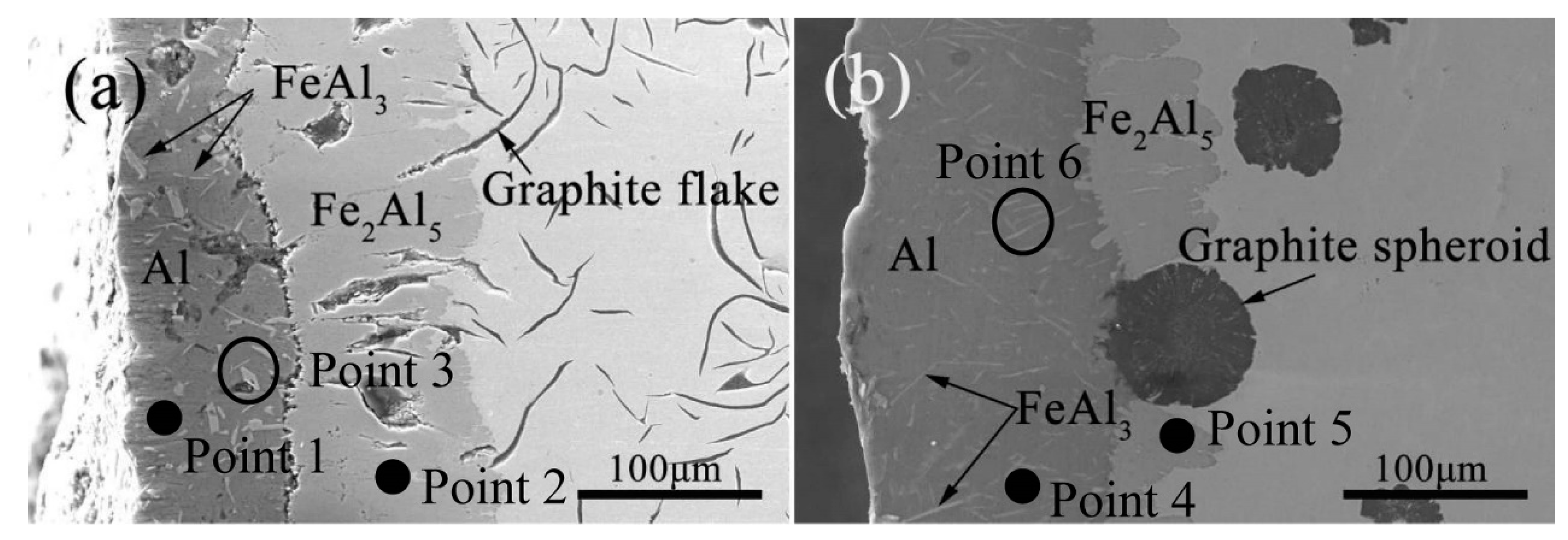
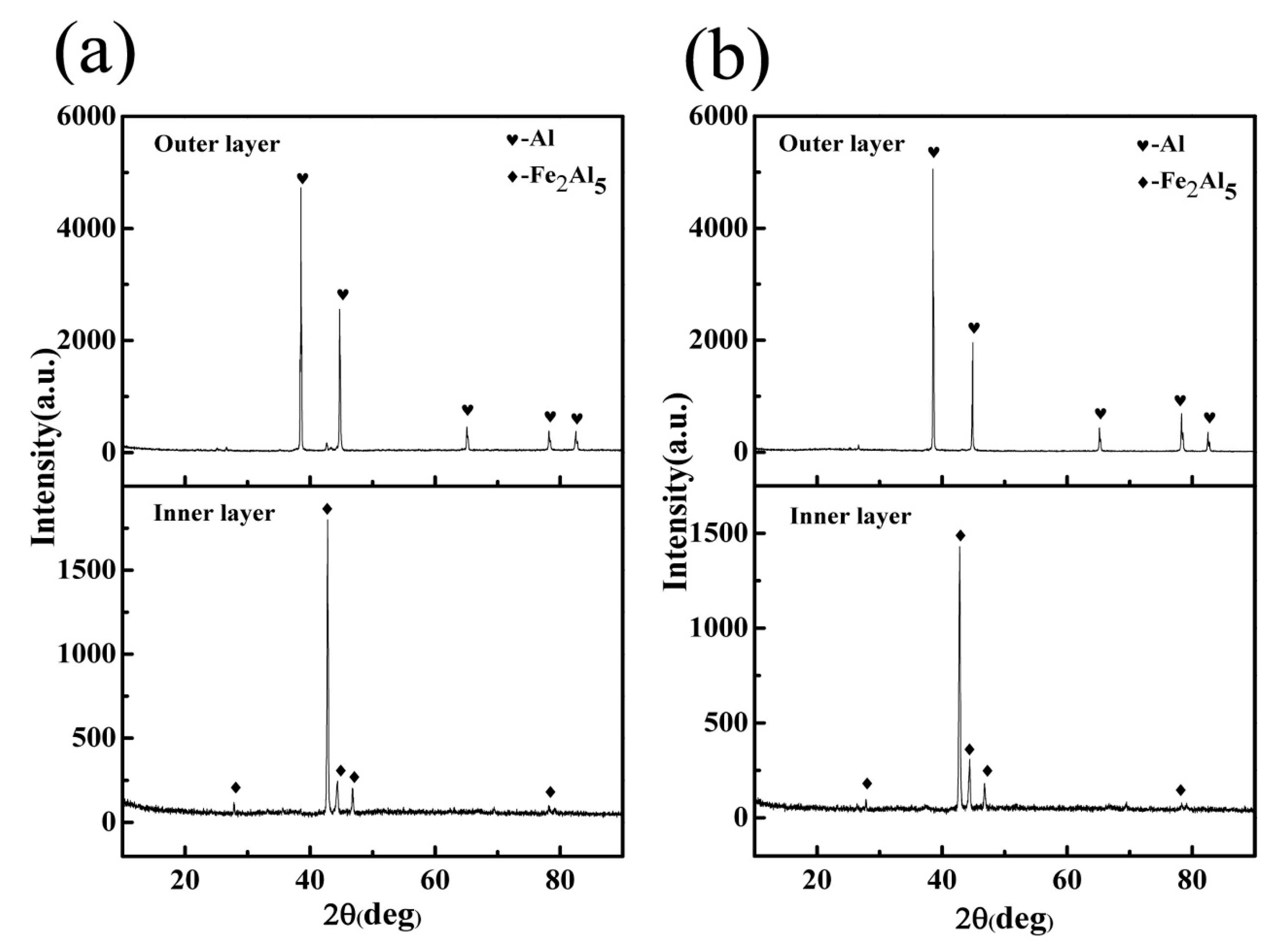
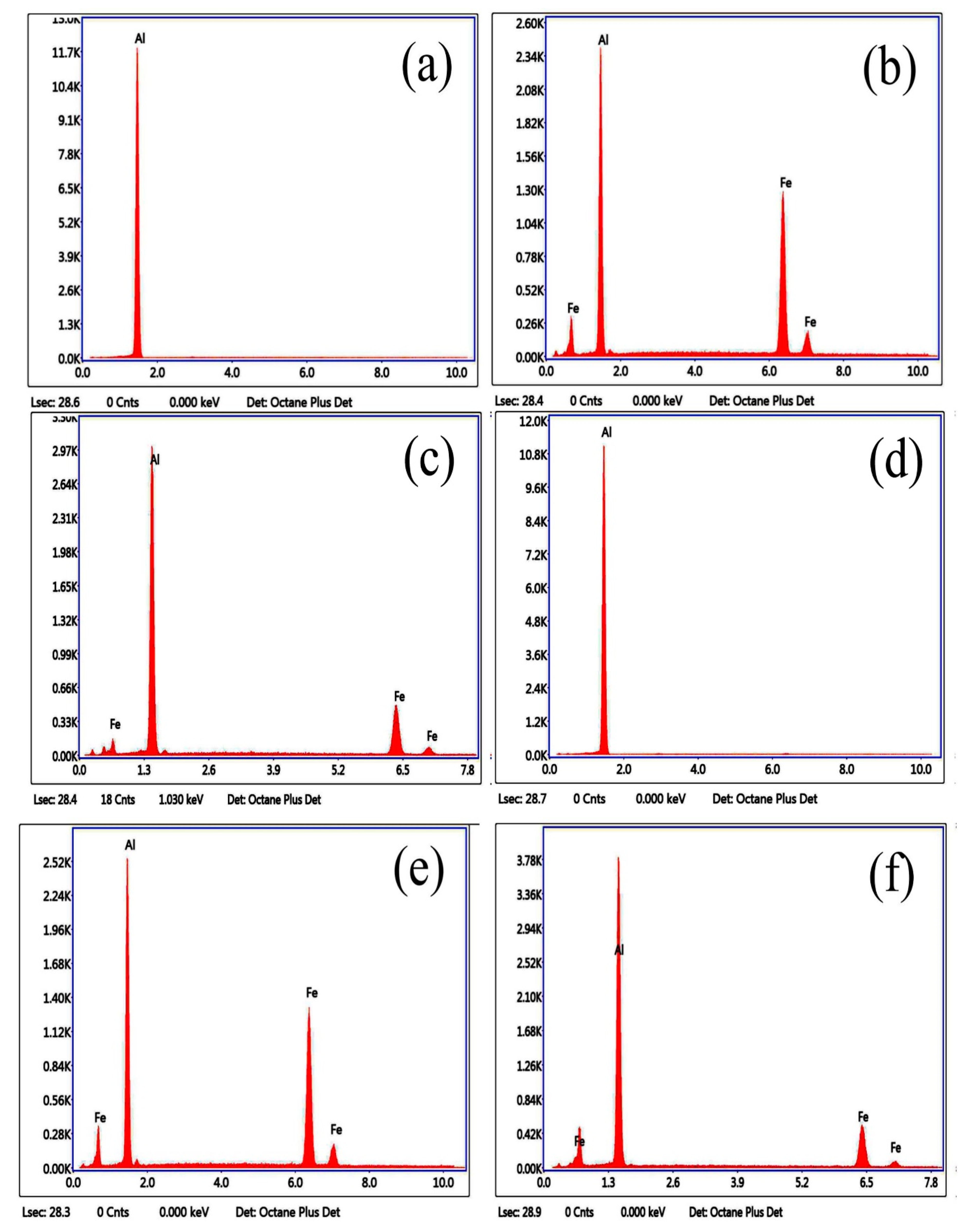
3.1. Microstructure and Phase of the Hot-Dip Aluminide Coating
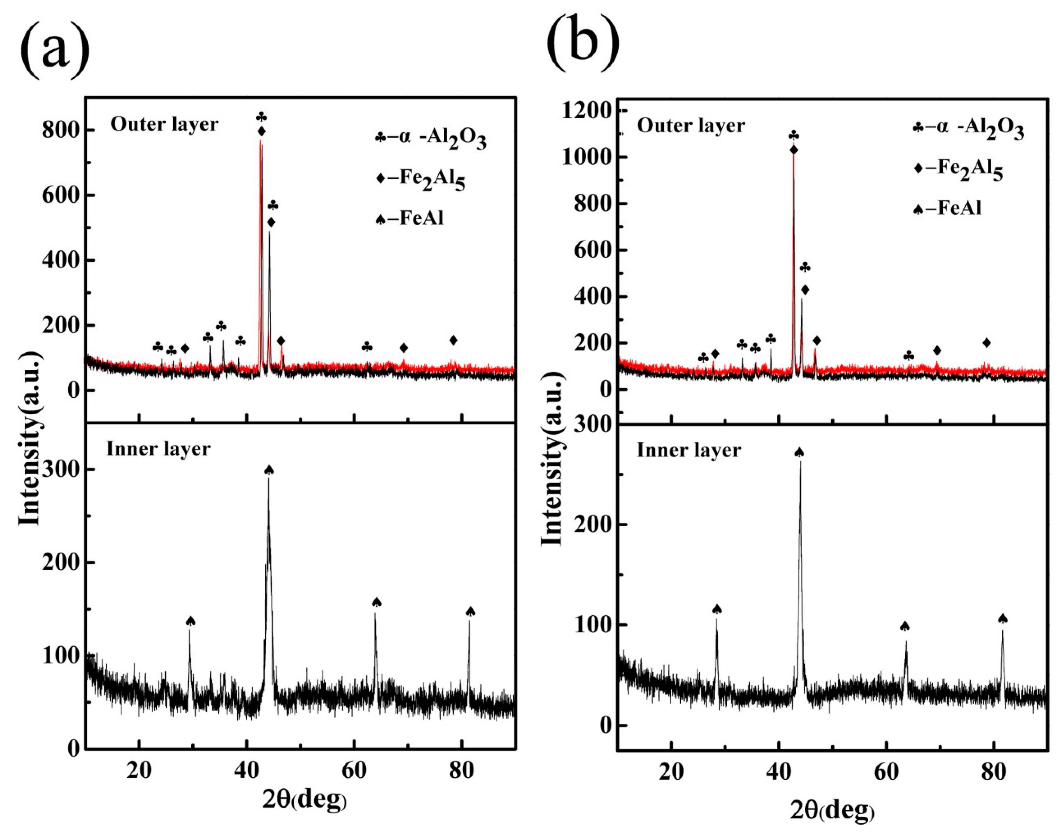
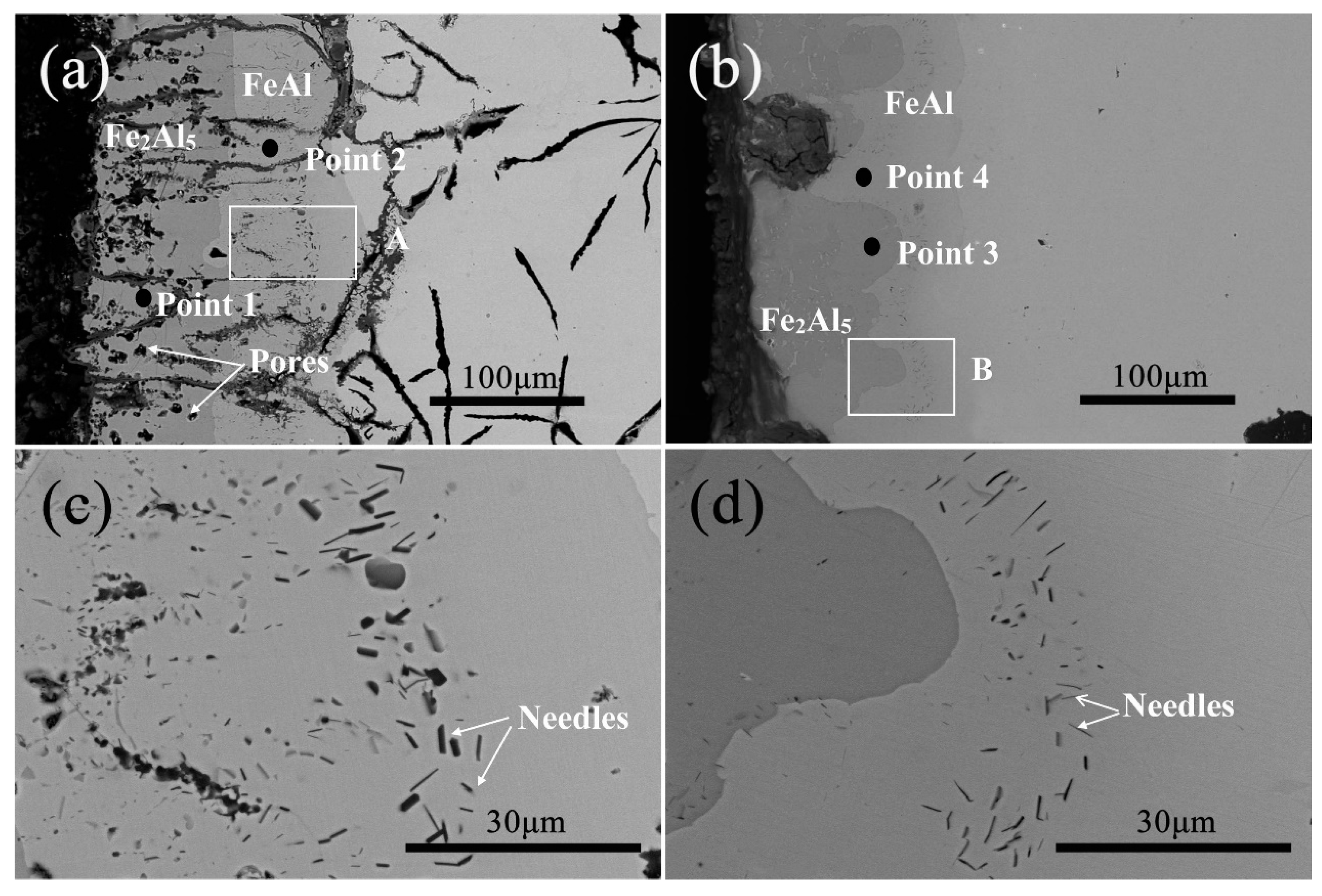
3.2. Microstructure and Phase of the HDDA Coating
3.3. High-Temperature Oxidation
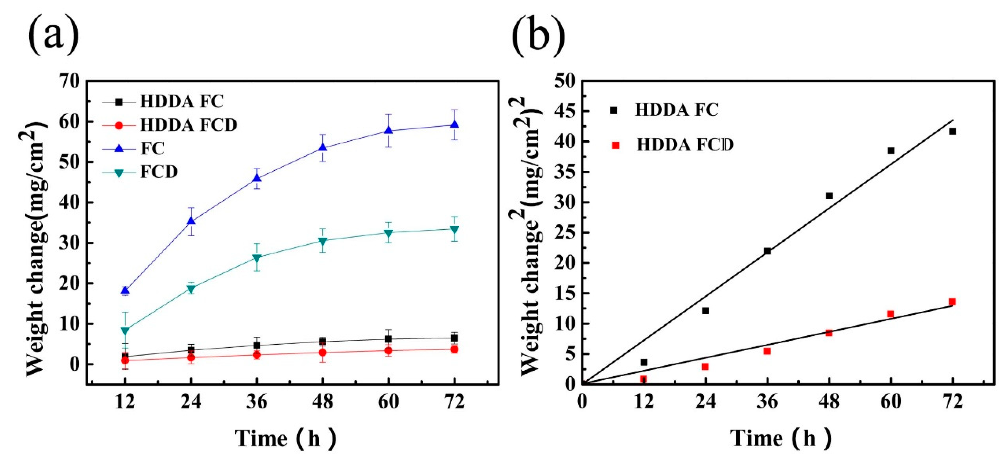
3.3.1. High-Temperature Oxidation Kinetic Curves
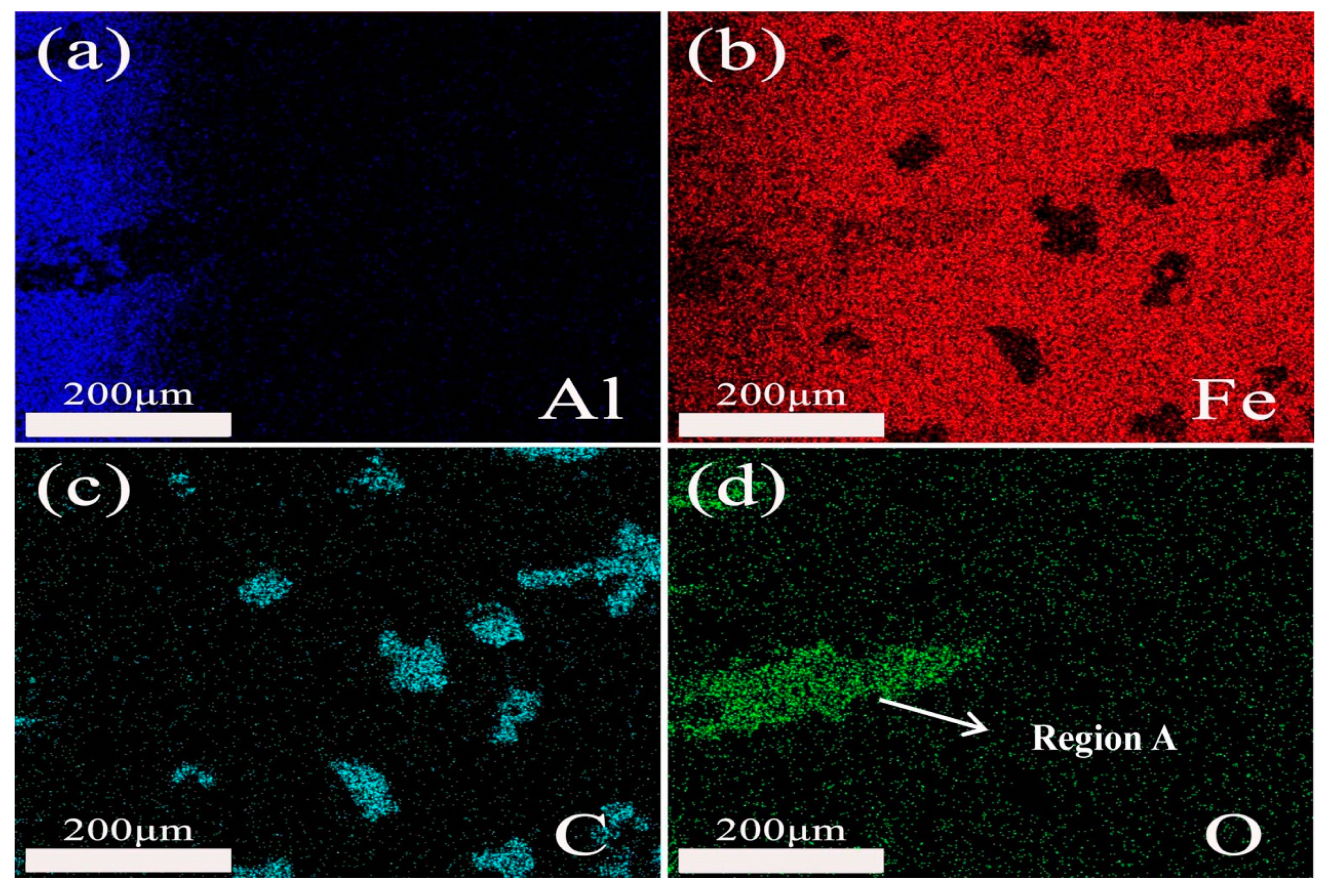
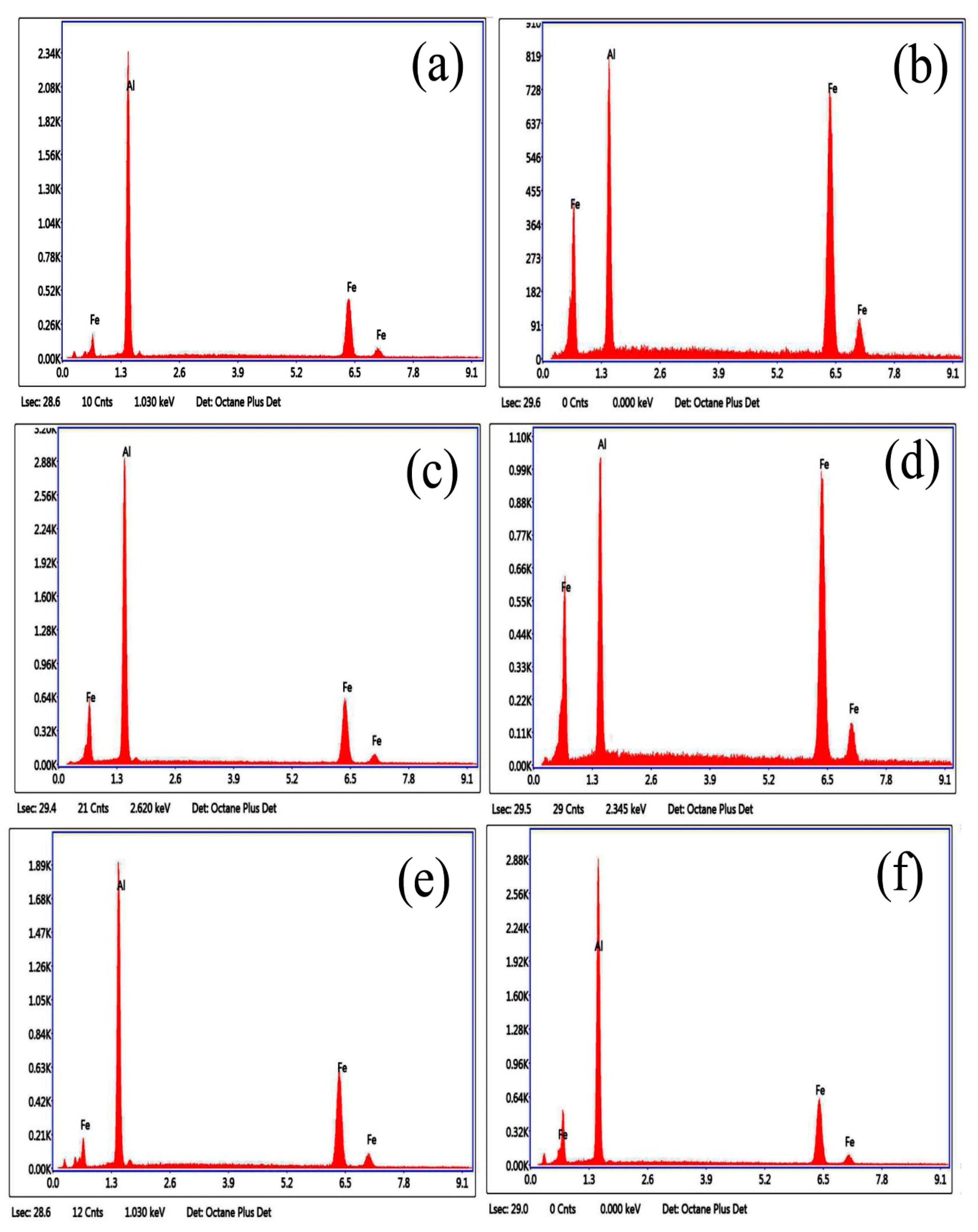
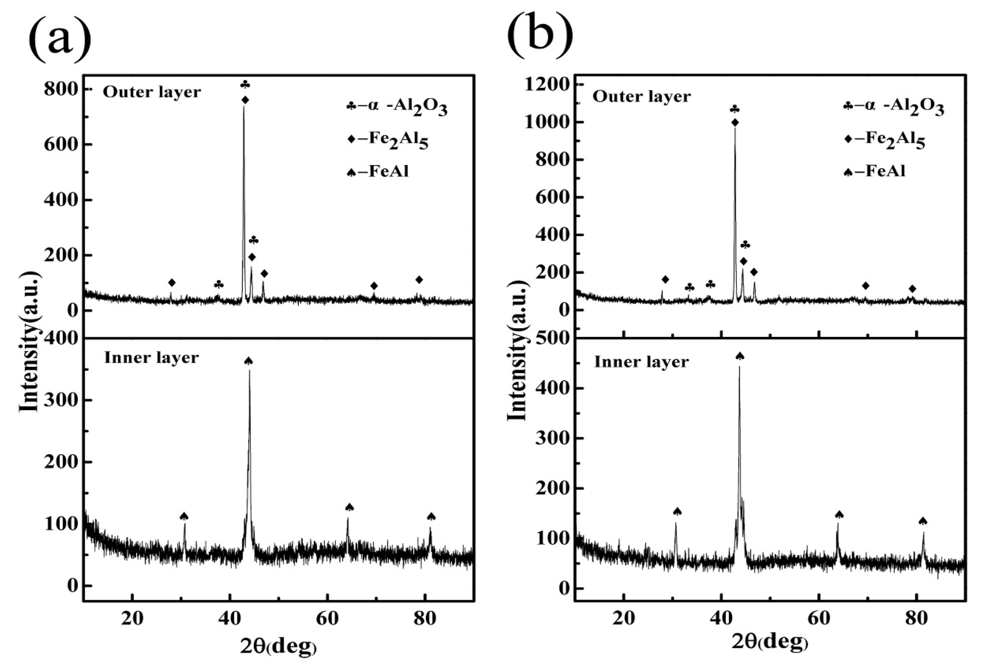
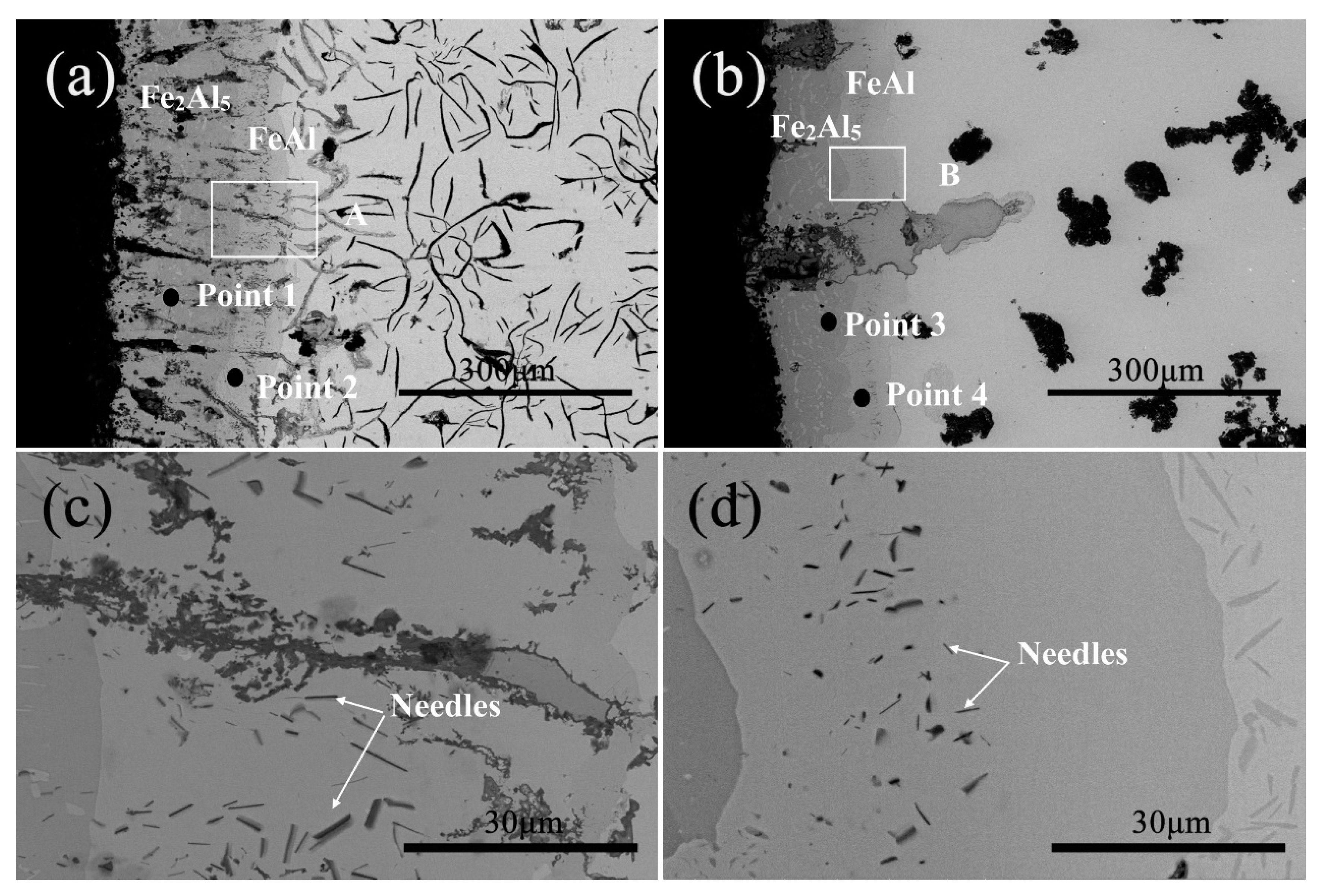
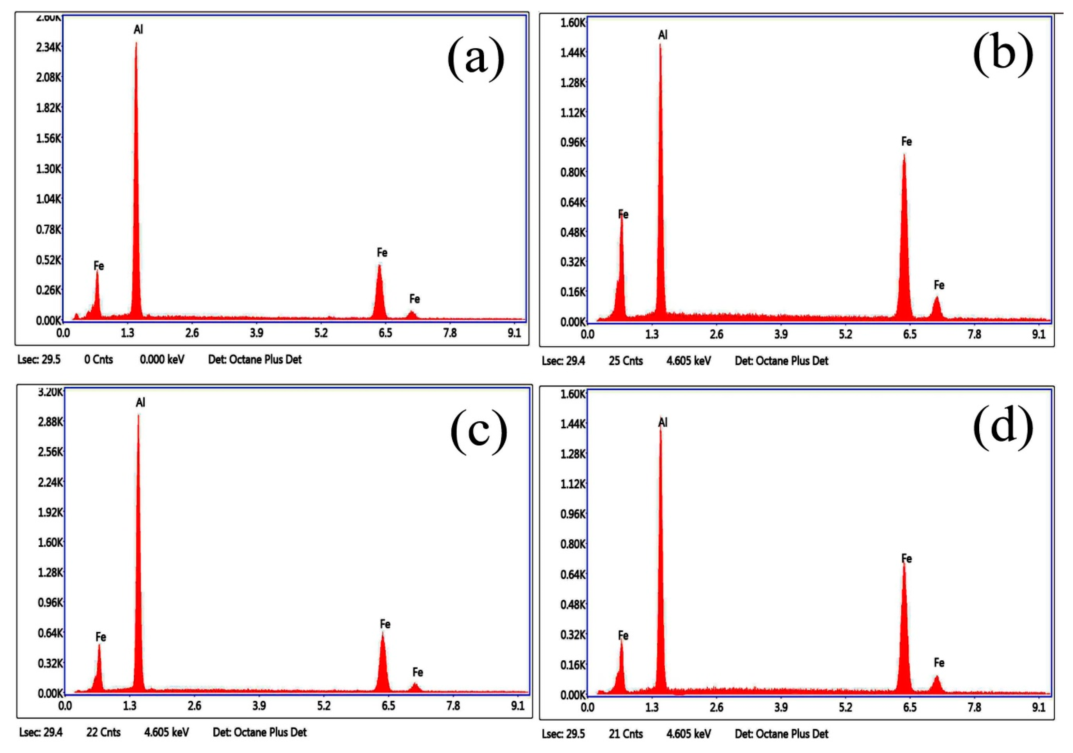
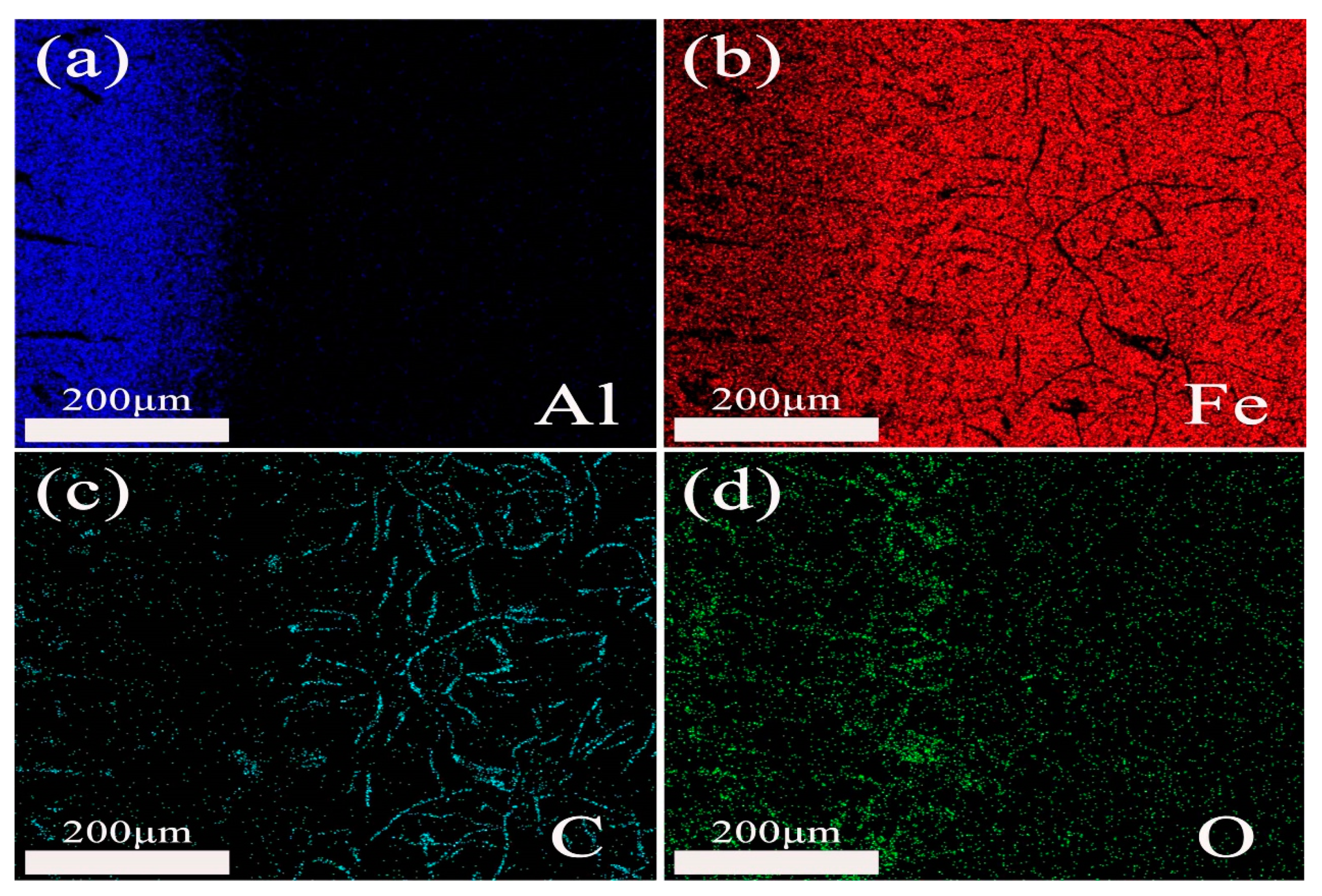
3.3.2. Microstructure and Phase of the HDDA Coating after Oxidation
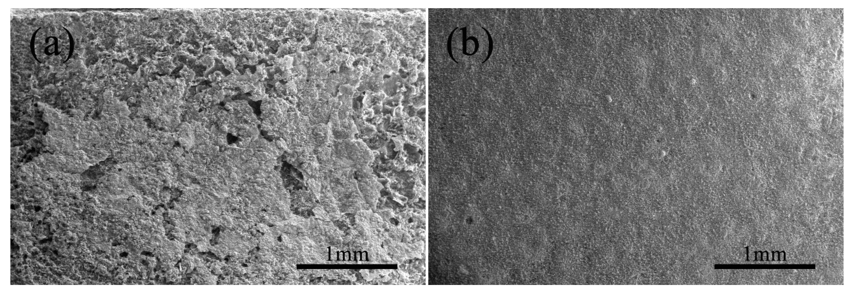
3.3.3. Surface Micrograph of the HDDA Coating after Oxidation
3.4. Abrasive Wear
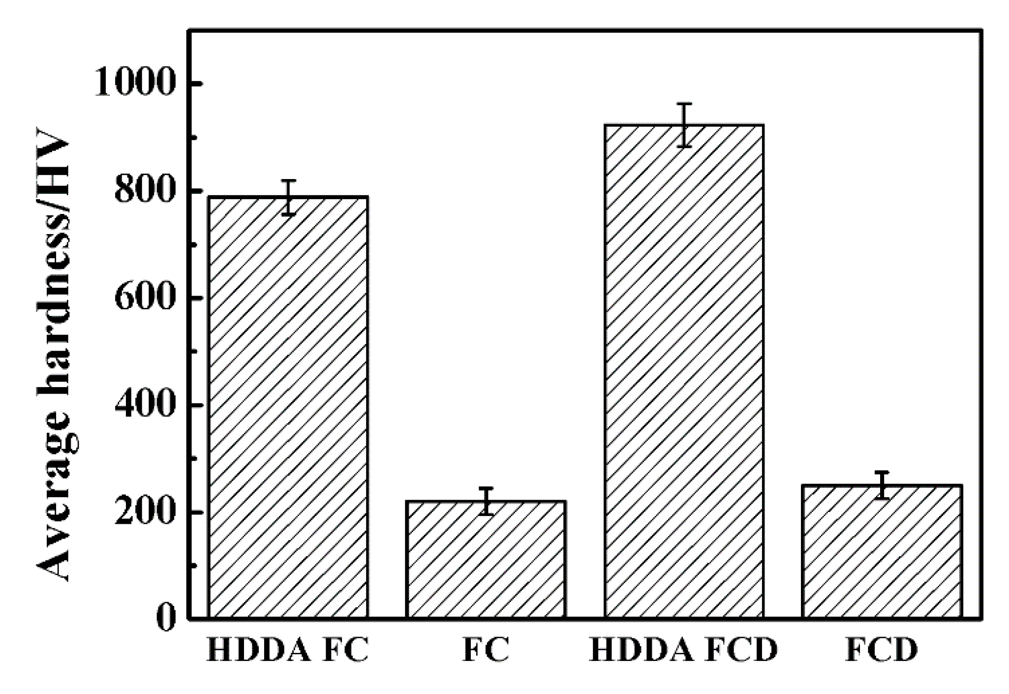
3.4.1. Hardness of the HDDA Coating
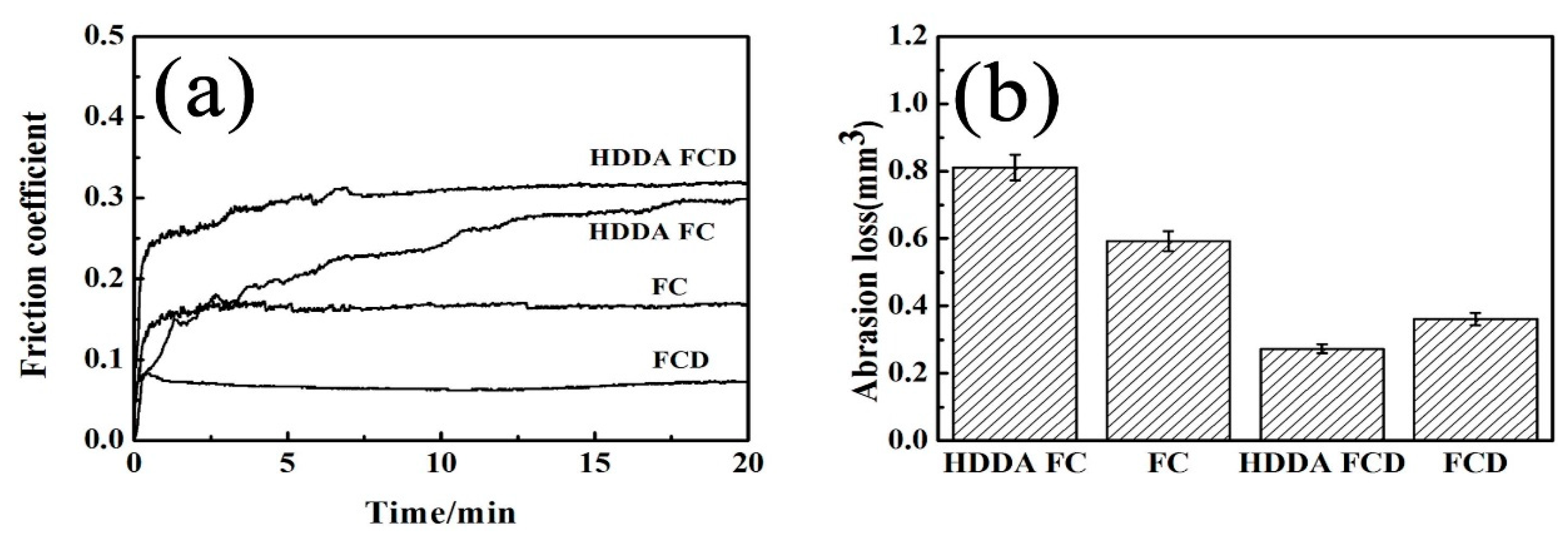
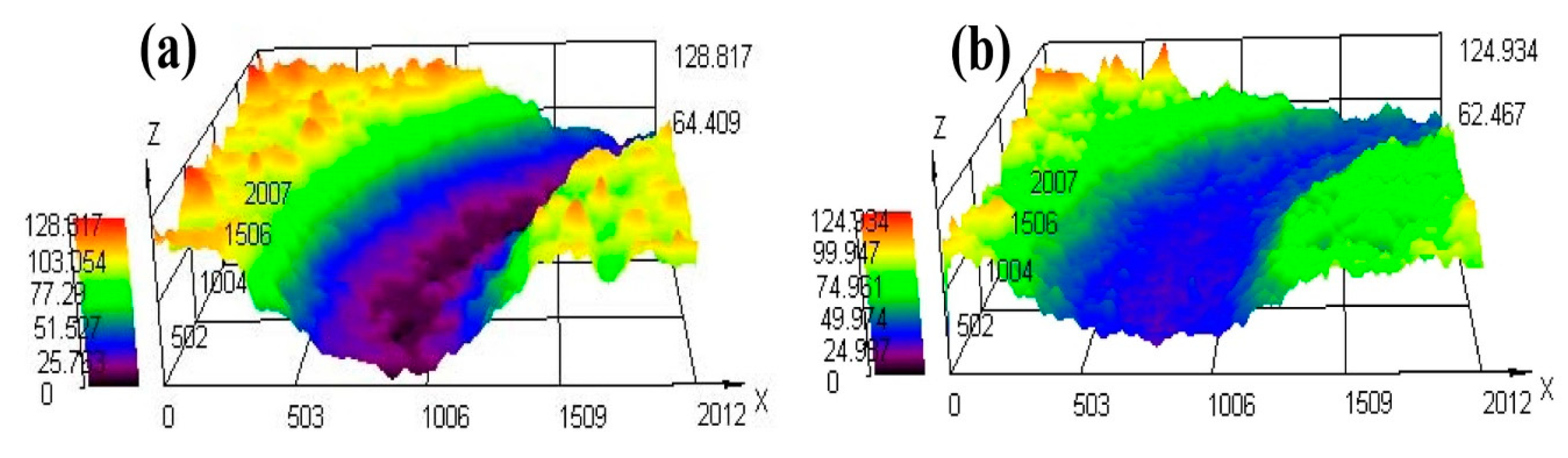
3.4.2. Friction Coefficient, Abrasion Loss and Wear Morphology
4. Conclusions
Author Contributions
Acknowledgments
Conflicts of Interest
References
- Li, K.R.; Zeng, Y.C.; Zhang, Z.C. New progress of cast iron production technology in China (2). Modern Cast Iron. 2016, 19–25. [Google Scholar] [CrossRef]
- Zhao, W.P.; Liu, Y.J.; Wang, H.; Ding, X.H.; Yang, Y.J.; Qie, Y.L.; Liu, J.Y. Analysis and solution of fracture of valve guide for a four cylinder engine. Small Intern. Combust. Engine Veh. Tech. 2015, 44, 48–51. [Google Scholar]
- Li, J.Y. Effect of phosphorus content on wear resistance of gray cast iron. Mech. Manag. Dev. 2005, 21–25. [Google Scholar] [CrossRef]
- Zhang, Z.; Wang, Y.; Xiao, L.; Zhang, L.; Su, Y.; Lin, J. High-temperature oxidation of hot-dip aluminizing coatings on a Ti3Al–Nb alloy and the effects of element additions. Corros. Sci. 2012, 64, 137–144. [Google Scholar] [CrossRef]
- Zhang, B.; Cai, H.; Zhang, Y.; Sun, W.-C.; Zhang, J.-M. Effect of Oxide Film Thickness on Electrical and Thermal Conductivity of Micro-arc Oxidize Aluminium Substrates. Surf. Technol. 2017, 46, 23–27. [Google Scholar]
- Li, Y.J.; Liang, T.Q.; Ao, R.; Zhao, H.; Chen, X.; Zeng, J. Oxidation resistance of iron-based coatings by supersonic arc spraying at high temperature. Surf. Coat. Technol. 2018, 347, 99–112. [Google Scholar] [CrossRef]
- Bozza, F.; Bolelli, G.; Giolli, C.; Giorgetti, A.; Lusvarghi, L.; Sassatelli, P.; Scrivani, A.; Candeli, A.; Thoma, M. Diffusion mechanisms and microstructure development in pack aluminizing of Ni-based alloys. Surf. Coat. Technol. 2014, 239, 147–159. [Google Scholar] [CrossRef]
- Fan, X.M.; Li, L.; Wen, H.Y.; Liu, S.F.; Li, Z.Q. Study on hot-diffusion aluminzing of cast iron and its high temperature oxidation resistance. Mater. Prot. 2005, 38, 48–50. [Google Scholar]
- Wu, D.; Zhang, X.; Wang, X. Comparative study on high temperature oxidation resistance of hot-dipped aluminum and hot-diffusion aluminizing steels. Autom. Instrum. 2013, 21–22. [Google Scholar] [CrossRef]
- Chen, N.; Wang, M.; Wang, H.-P.; Wan, Z.; Carlson, B.E. Microstructural and mechanical evolution of Al/steel interface with Fe2Al5 growth in resistance spot welding of aluminum to steel. J. Manuf. Process. 2018, 34, 424–434. [Google Scholar] [CrossRef]
- Cheng, W.-J.; Wang, C.-J. High-temperature oxidation behavior of hot-dipped aluminide mild steel with various silicon contents. Appl. Surf. Sci. 2013, 274, 258–265. [Google Scholar] [CrossRef]
- Majumdar, S.; Paul, B.; Kain, V.; Dey, G.K. Formation of Al2O3/Fe-Al coatings on SS 316 surface by pack aluminizing and heat treatment. Mater. Chem. Phys. 2017, 190, 31–37. [Google Scholar] [CrossRef]
- Lin, M.B.; Wang, C.J.; Volinsky, A.A. Isothermal and thermal cycling oxidation of hot-dip aluminide coating on flake/spheroidal graphite cast iron. Surf. Coat. Technol. 2011, 206, 1595–1599. [Google Scholar] [CrossRef]
- Hatate, M.; Shiota, T.; Takahashi, N.; Shimizu, K. Influences of graphite shapes on wear characteristics of austempered cast iron. Wear 2001, 251, 885–889. [Google Scholar] [CrossRef]
- Wang, W.; Du, A.; Fan, Y.; Zhao, X.; Wang, X.; Ma, R.; Li, Q. Microstructure and tribological properties of SiC matrix composites infiltrated with an aluminium alloy. Tribol. Int. 2018, 120, 369–375. [Google Scholar] [CrossRef]
- Zhang, J.W.; Fan, Y.Z.; Zhao, X.; Ma, R.; Du, A.; Cao, X. Influence of duty cycle on the growth behavior and wear resistance of microarc oxidation coatings on hot dip aluminized cast iron. Surf. Coat. Technol. 2018, 337, 141–149. [Google Scholar] [CrossRef]
- Awan, G.H.; Hasan, F.U. The morphology of coating/substrate interface in hot-dip-aluminized steels. Mater. Sci. Eng. A 2008, 472, 157–165. [Google Scholar] [CrossRef]
- Lin, M.B.; Wang, C.J. Microstructure and high temperature oxidation behavior of hot-dip aluminized coating on high silicon cast iron. Surf. Coat. Technol. 2010, 205, 1220–1224. [Google Scholar] [CrossRef]
- Nouri, S.; Rastegari, S.; Mirdamadi, S.; Hadavi, M. Formation of Diffusion Aluminide Coatings on γ-TiAl Alloy with In-Pack and Out-Pack Processes. Trans. Indian Inst. Met. 2015, 68, 867–871. [Google Scholar] [CrossRef]
- Jeng, S.C. Oxidation behavior and microstructural evolution of hot-dipped aluminum coating on Ti-6Al-4V alloy at 800 °C. Surf. Coat. Technol. 2013, 235, 867–874. [Google Scholar] [CrossRef]
- Lee, J.W.; Kuo, Y.C. A study on the microstructure and cyclic oxidation behavior of the pack aluminized Hastelloy X at 1100 °C. Surf. Coat. Technol. 2006, 201, 3867–3871. [Google Scholar] [CrossRef]
- Wang, C.J.; Badaruddin, M. The dependence of high temperature resistance of aluminized steel exposed to water-vapour oxidation. Surf. Coat. Technol. 2011, 205, 1200–1205. [Google Scholar] [CrossRef]
- Wang, H.-X.; Zhang, Y.; Cheng, J.-L.; Li, Y.-S. High temperature oxidation resistance and microstructure change of aluminized coating on copper substrate. Trans. Nonferrous Met. Soc. China 2015, 25, 184–190. [Google Scholar] [CrossRef]
- Khoshhal, R. Investigation of oxidation behavior of synthesized Fe2Al5 and FeAl. Metal Powder Report. 2019, 74, 30–34. [Google Scholar] [CrossRef]
- Wang, Y.S.; Xiong, J.; Yan, J.; Fan, H.; Wang, J. Oxidation resistance and corrosion behavior of hot-dip aluminized coatings on commercial-purity titanium. Surf. Coat. Technol. 2011, 206, 1277–1282. [Google Scholar] [CrossRef]
- Zhang, X.-M.; Chen, W.-P. Review on corrosion-wear resistance performance of materials in molten aluminum and its alloys. Trans. Nonferrous Met. Soc. China 2015, 25, 1715–1731. [Google Scholar] [CrossRef]
- Zhang, Q.; Zhou, Y.; Liu, J.; Chen, K.; Mo, J.; Cui, X.; Wang, S. Comparative research on dry sliding wear of hot-dip aluminized and uncoated AISI H13 steel. Wear 2015, 344, 22–31. [Google Scholar] [CrossRef]


| Alloy | C | Si | Mn | P | S | Fe |
|---|---|---|---|---|---|---|
| FC | 3.00 | 0.80 | 1.20 | 0.50 | 0.02 | Balance |
| FCD | 3.00 | 1.60 | 0.70 | 0.50 | 0.02 | Balance |
| Point | Al (at.%) | Fe (at.%) |
|---|---|---|
| 1 | 100.00 | 0.00 |
| 2 | 70.82 | 29.18 |
| 3 | 74.25 | 25.75 |
| 4 | 100.00 | 0.00 |
| 5 | 71.71 | 28.29 |
| 6 | 76.44 | 23.56 |
| Point | Al (at.%) | Fe (at.%) |
|---|---|---|
| 1 | 70.91 | 29.09 |
| 2 | 42.18 | 57.82 |
| 3 | 70.94 | 29.06 |
| 4 | 43.76 | 56.24 |
| Needle (FC) | 62.92 | 37.08 |
| Needle (FCD) | 68.69 | 31.31 |
| Alloy | Kp |
|---|---|
| HDDA FC | 1.84 × 10⁻⁴ |
| HDDA FCD | 6.13 × 10⁻⁵ |
| Point | Al (at.%) | Fe (at.%) |
|---|---|---|
| 1 | 72.11 | 27.89 |
| 2 | 51.00 | 49.00 |
| 3 | 70.91 | 29.09 |
| 4 | 55.66 | 44.34 |
| Alloy | Wear Depth | Wear Width |
|---|---|---|
| HDDA FC | 101.25 | 1.14 |
| HDDA FCD | 49.73 | 0.75 |
© 2019 by the authors. Licensee MDPI, Basel, Switzerland. This article is an open access article distributed under the terms and conditions of the Creative Commons Attribution (CC BY) license (http://creativecommons.org/licenses/by/4.0/).
Share and Cite
Zhang, Y.; Fan, Y.; Zhao, X.; Du, A.; Ma, R.; Wu, J.; Cao, X. Influence of Graphite Morphology on Phase, Microstructure, and Properties of Hot Dipping and Diffusion Aluminizing Coating on Flake/Spheroidal Graphite Cast Iron. Metals 2019, 9, 450. https://doi.org/10.3390/met9040450
Zhang Y, Fan Y, Zhao X, Du A, Ma R, Wu J, Cao X. Influence of Graphite Morphology on Phase, Microstructure, and Properties of Hot Dipping and Diffusion Aluminizing Coating on Flake/Spheroidal Graphite Cast Iron. Metals. 2019; 9(4):450. https://doi.org/10.3390/met9040450
Chicago/Turabian StyleZhang, Yu, Yongzhe Fan, Xue Zhao, An Du, Ruina Ma, Jianjun Wu, and Xiaoming Cao. 2019. "Influence of Graphite Morphology on Phase, Microstructure, and Properties of Hot Dipping and Diffusion Aluminizing Coating on Flake/Spheroidal Graphite Cast Iron" Metals 9, no. 4: 450. https://doi.org/10.3390/met9040450
APA StyleZhang, Y., Fan, Y., Zhao, X., Du, A., Ma, R., Wu, J., & Cao, X. (2019). Influence of Graphite Morphology on Phase, Microstructure, and Properties of Hot Dipping and Diffusion Aluminizing Coating on Flake/Spheroidal Graphite Cast Iron. Metals, 9(4), 450. https://doi.org/10.3390/met9040450