1. Introduction
TC17 (Ti–5Al–2Sn–2Zr–4Mo–4Cr) is a dual-phase (α + β) titanium alloy that is rich in β-stabilizing elements. Owing to a series of advantages, such as high strength, good fracture toughness, high hardenability, and wide forging temperature range, it can be used to achieve a good match between strength, plasticity, and excellent comprehensive mechanics performance and to meet the requirements of damage tolerance design, high structural efficiency, and low manufacturing cost. TC17 titanium alloy has good forgeability and thermal processing properties, thus it is applied in hot-die forging and forging under constant moisture. The working temperature of TC17 titanium alloy can reach up to 450 °C, so it has been used in the manufacturing of aeroengine fans and compressor discs and in the forging of large-section pieces [
1,
2,
3,
4].
As an efficient and advanced welding method, linear friction welding (LFW) has been employed by researchers in the manufacture of blisks, and thus it has become a key technology in the manufacturing and maintenance of aeroengines with high thrust-to-weight ratio [
5,
6,
7,
8]. Compared to blank processing, the use of the linear friction welding technology in the manufacture of titanium alloy blisks is more economical and can minimize the manufacturing cycles. Moreover, the use of the linear friction welding technology also allows the detachment and repair of blades damaged by birds and has greater flexibility in material selection and performance combinations. Since the forming mechanism of linear friction welding is completely different from those of the existing welding processes, the structure of the joint is also different. During the linear friction welding process, the coupling effect of thermal stress and mechanical stress always acts at the friction interface and at the metal proximal to the interface of the joint. As a result, a series of complicated changes occur, including plastic deformation, dynamic recovery, grain recrystallization and growth, dissolution and precipitation of alloy phases, and microstructure transformation. Because of the varieties of temperature and strain rate from the base metal (BM) to the center of the joint, the microstructure from the BM to the center of the joint changes significantly.
The difference in microstructure between the different zones of the linear friction welding joint significantly affects the micro-region performance of the joint, and the linear friction welding joint of each material has unique characteristics [
9,
10,
11,
12]. In linear friction welding joint of TC4 titanium alloy, the microstructure is α” martensite in the weld zone (WZ), and the thermo-mechanically affected zone (TMAZ) is a deformed primary α phase and a deformed α + β structure, in addition to a small amount of martensite [
13,
14,
15,
16]. The microstructure at the central weld zone of the as-welded Ti6246 LFW joint consists of fine grains with dense acicular orthorhombic α’ martensite. Phase transformation from orthorhombic α” to hexagonal α occurred after heat treatment, leading to the observed hardness increase [
9]. A narrow zone of ±2 mm from the friction interface formed when reaching the isothermal α → β transformation temperature, and a ±3 mm wide soft Process-Affected Zone was delimited by three characteristic zones in the Ti17 LFW joint. The total dissolution of the α phase occurred in the joint core, and strongly textured {110}<111> β recrystallized grains formed in the weld line by continuous dynamic recrystallization of squeezed prior-β grains in the TMAZ. A gradual loss of hardness occurred in the hot affect zone (HAZ), whose microstructure was similar to the one of the base material but was subject to gradual α laths dissolution [
17]. The WZ of Ni-based superalloy linear friction welding joint has fine grains, and its TMAZ is composed of a deformed grain structure that contains a large number of twinning crystals [
18,
19,
20,
21]. In aluminum alloys, the main microstructure of the WZ and the TMAZ is deformed aluminum alloy grains [
22,
23]. The carbon steel linear friction welding joint has fine pearlite and ferrite structures, and the TMAZ is composed of deformed pearlite, ferrite, and tempered martensite structures [
24,
25].
At present, research on the linear friction welding technology mainly focuses on the linear friction welding process of different materials, the evolution and variation of the joint microstructure, and numerical simulations [
26,
27]. Research on joint fracture performance is relatively limited. In order to systematically characterize, evaluate, and apply the linear friction welding joint, it is essential to analytically determine the fracture toughness. At the same time, it is necessary to understand the relationship between the linear friction welding process, the alloy microstructure, and the properties of the joint microstructure. Meanwhile, the influence of different microstructures on the fracture process needs to be investigated to provide reliable data for the structural design.
The microstructure of the WZ of the TC17 linear friction welding joint and the grain and phase of the TMAZ have obvious differences [
28,
29,
30]. After heat treatment, the WZ has a large number of lamellar α phase structures distributed among the fine grains. The TMAZ is composed of deformed β grains and ground β grains containing deformed α phase and lamellar α phase. The difference in microstructure affects the fracture toughness of the joint micro-domains. In this paper, the fracture toughness of each typical zone of the TC17 titanium alloy linear friction welding joint, usually used in blisks, was measured and analyzed using the fracture mechanics method, providing technical knowledge for the engineering application of the linear friction welding technology.
2. Materials and Methods
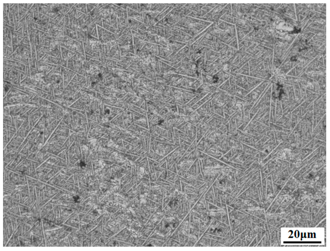
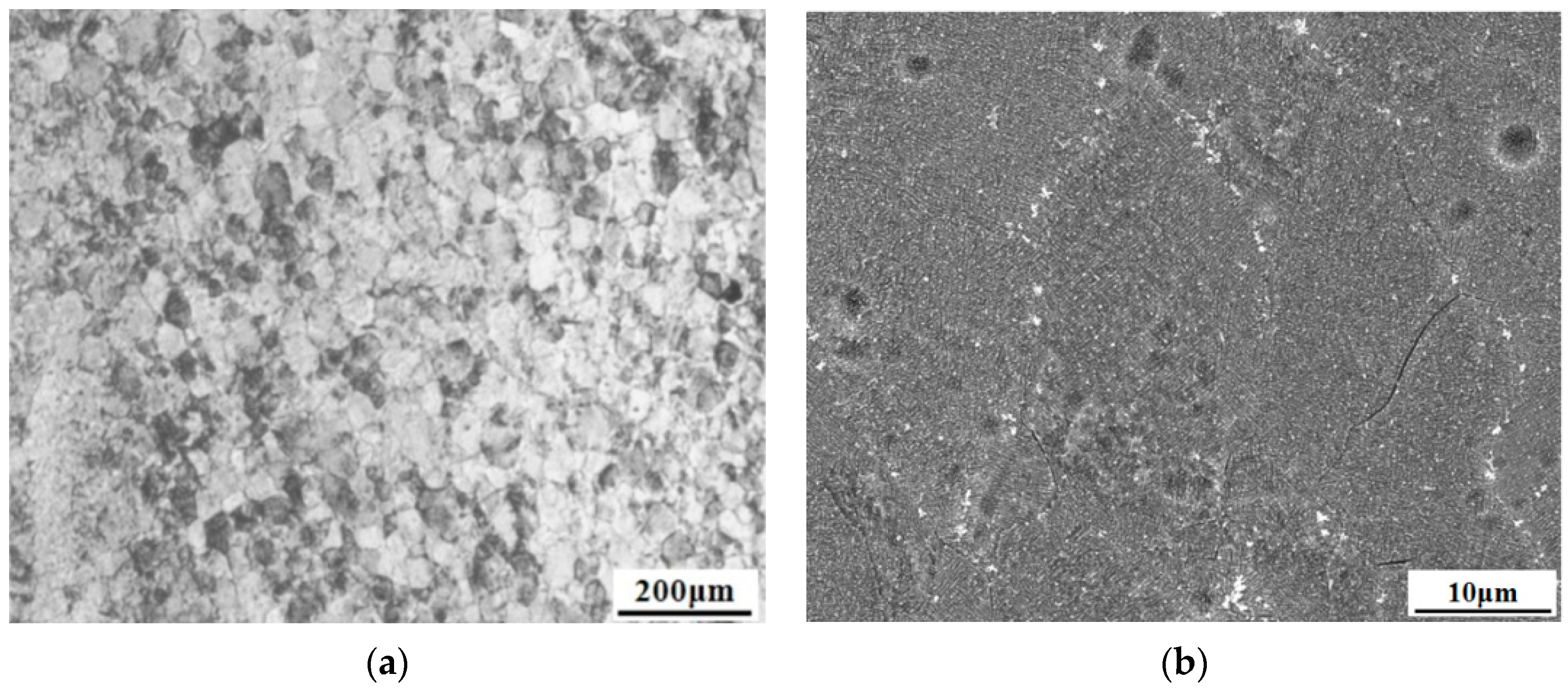
In the present study, the TC17 titanium alloy was used for the experiments. It is a near-β (α + β) titanium alloy with a basket-shaped structure. The lamellar α phase is randomly arranged on the coarser β grains, where the average grain size of the β phase is about 500 μm, the thickness of the lamellar α is about 2 μm, and the length ranges between 15 and 30 μm, as shown in
Figure 1. The phase transition point resulted to be TC17 is 895 °C by the method of metallographic observation. Compared to the commonly used dual-phase Ti alloys, the TC17 titanium alloy has high yielding strength and good high-cycle fatigue. Compared to the β titanium alloy, TC17 has low density and a high elastic modulus; its chemical composition can be seen in
Table 1.
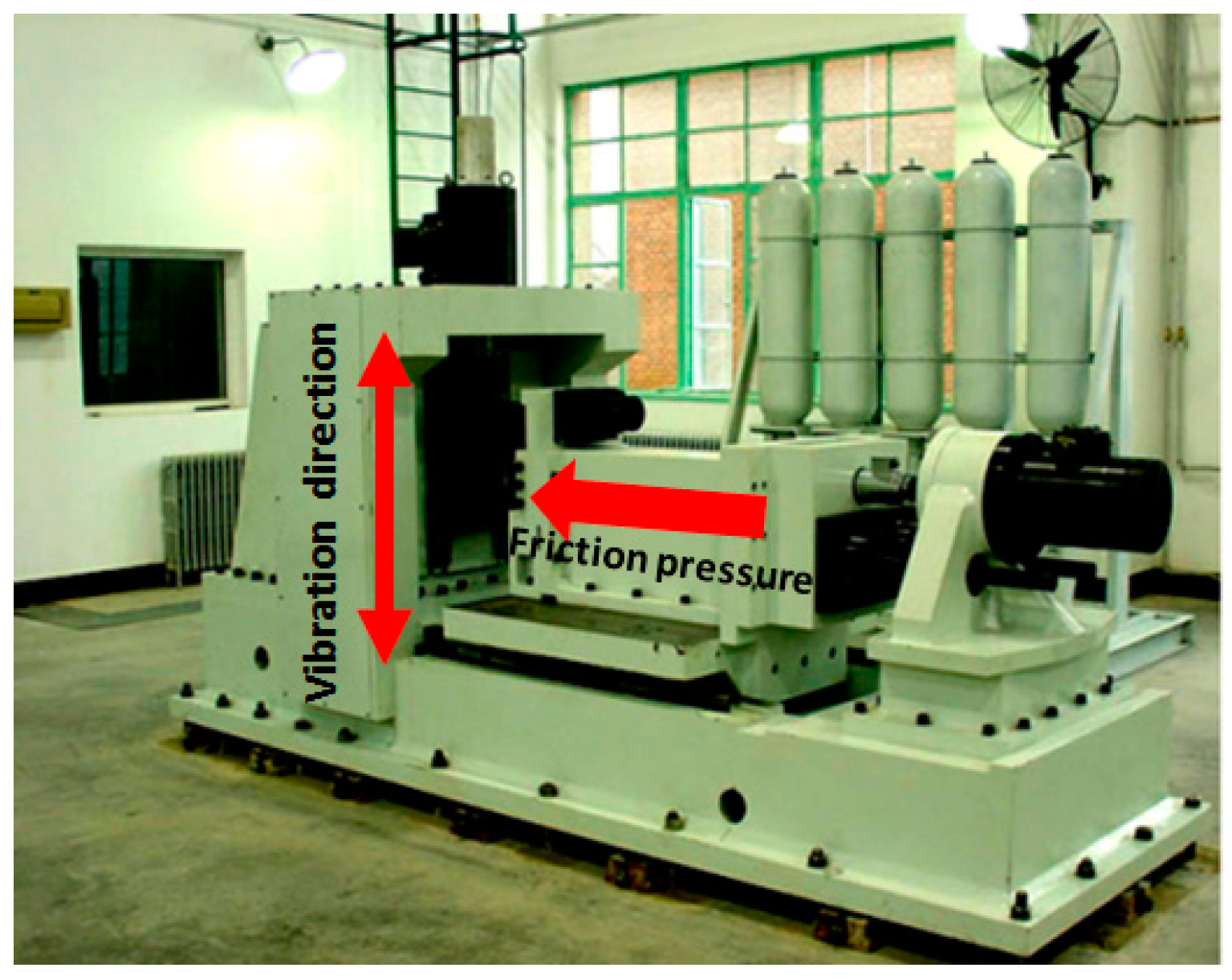
The linear friction welding test was carried out on the LFW-20T homemade welding machine (AVIC Manufacturing Technology Institute, Beijing, China), developed by AVIC Manufacturing Technology Institute. The equipment can be observed in
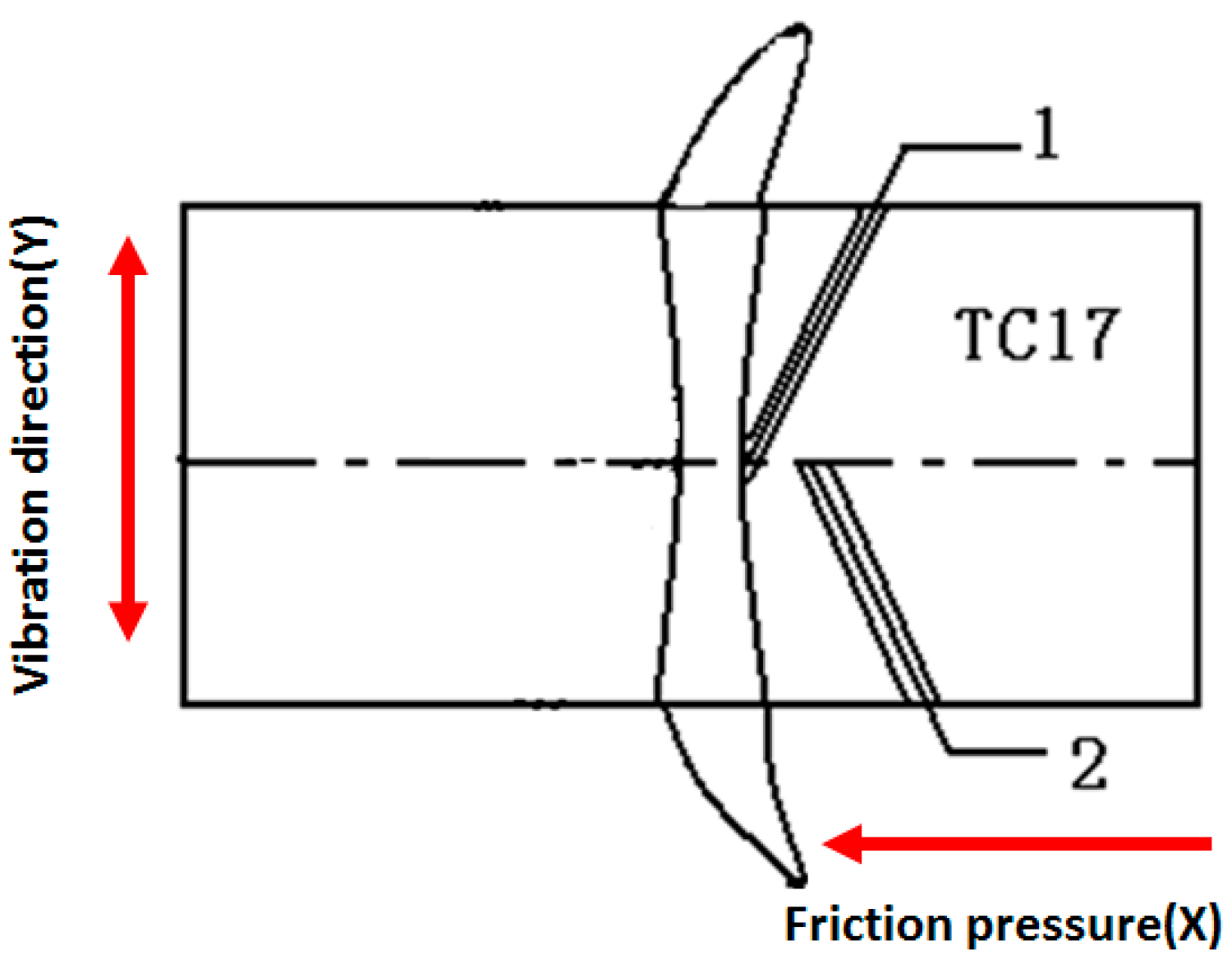
Figure 2. The optimized process parameters of TC17 LFW were 3 mm (amplitude), 50 Hz (frequency), 15 T (friction pressure). The size of TC17 LFW sample was 20 mm (Z) × 75 mm (Y) × 120 mm (X). Y is the vibration direction, X is the direction of friction pressure, and the friction surface was 20 mm (Z) × 75 mm (Y). After linear friction welding, the joint was subjected to heat treatment at 630 °C for 3 h and then was cooled in a furnace. A WRN-120 single-stack Ni–Cr Ni–Al thermocouple was directly inserted into a hole of the welded specimen to monitor the temperature during the welding process. In
Figure 3, positions 1 and 2 represent the positions where the temperature was measured.
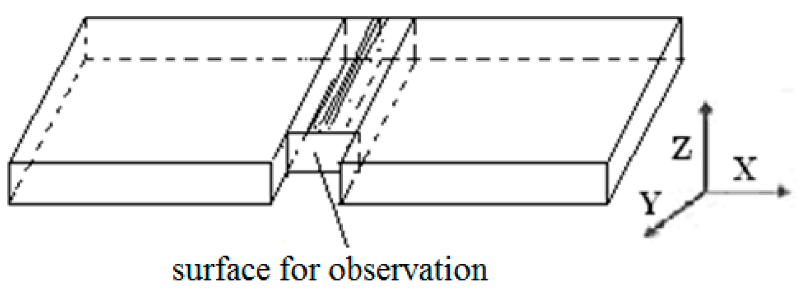
The joint microstructure analysis was performed using an Olympus BX41M optical microscope (Olympus Corporation, Tokyo, Japan) and a ZEISS SUPRA55 field-emission scanning electron microscope (SEM) (Carl Zeiss, Jena, Germany) at AVIC Manufacturing Technology Institute. The position of the sample that was studied is shown in
Figure 4, and the observation surface was the X-Z plane. After welding, the flash was removed. Firstly, wire cutting was carried out at the two sides, 5 cm away from the center of the joint, and then the sample was cut perpendicular to the direction of the joint. The specimen to be measured was subjected to mechanical grinding, polishing, and corrosion using a hydrofluoric acid/nitric acid aqueous solution at a certain ratio. The sample used for the microhardness measurement was subjected to inlaying, sanding, polishing, and etching. The microhardness measurement was carried out on an FM-700 microhardness tester (FUTURE-TECH CORP., Kawasaki, Japan). A load of 0.2 kg was applied for 15 s. The separation between indentation points along the X and Y directions was 0.2 mm and 0.5 mm, respectively. The microhardness of the as-welded and post-weld heat-treated joints was tested in each sample.
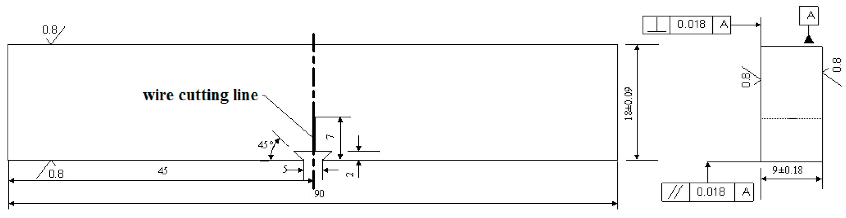
The fracture toughness tests were carried out on the WZ and TMAZ of the TC17 titanium alloy linear friction welding joint at room temperature using a pre-cracked single-edge notched three-point bending specimen. The fracture toughness can directly reflect the toughness of the material structure at the tip of the crack, so that it is necessary for the crack tip to fall within the target area of the specimen. The fracture toughness test piece was cut perpendicular to the welded surface, and the prefabricated cracks were within the WZ and the TMAZ. The fracture toughness sample was processed according to JB/T4291-1999, and the test piece had a thickness of
B = 9 mm, a width of
W = 2
B = 18 mm, a span of
S = 4
W = 72 mm, and a length of
L = 90 mm. The dimensions of the test piece can be seen in
Figure 5. Six fracture toughness samples were taken from the same TC17 LFW joint, three of them were used for the TMAZ and the other three were used for the WZ.
In linear friction welding joints made of the same material, the joint can be divided into the TMAZ and the WZ, although the joint microstructure exhibits a gradient variation. Considering the welding condition of TC17 titanium linear friction welding, the yielding stresses
δy (yielding point
δs or yielding strength
δ0.2) of the interfacial zone and the thermoplastically affected zone were difficult to be determined, so the following equations were employed
δ:
where
δ is the opening displacement of the crack tip (mm),
W denotes the width of the test piece (mm),
ɑ denotes the original crack length (mm),
γ denotes the rotation factor, and
V denotes the opening displacement measured by clip extensometers at both sides of the crack opening (mm). For the three-point bending test piece,
γ = 0.45.
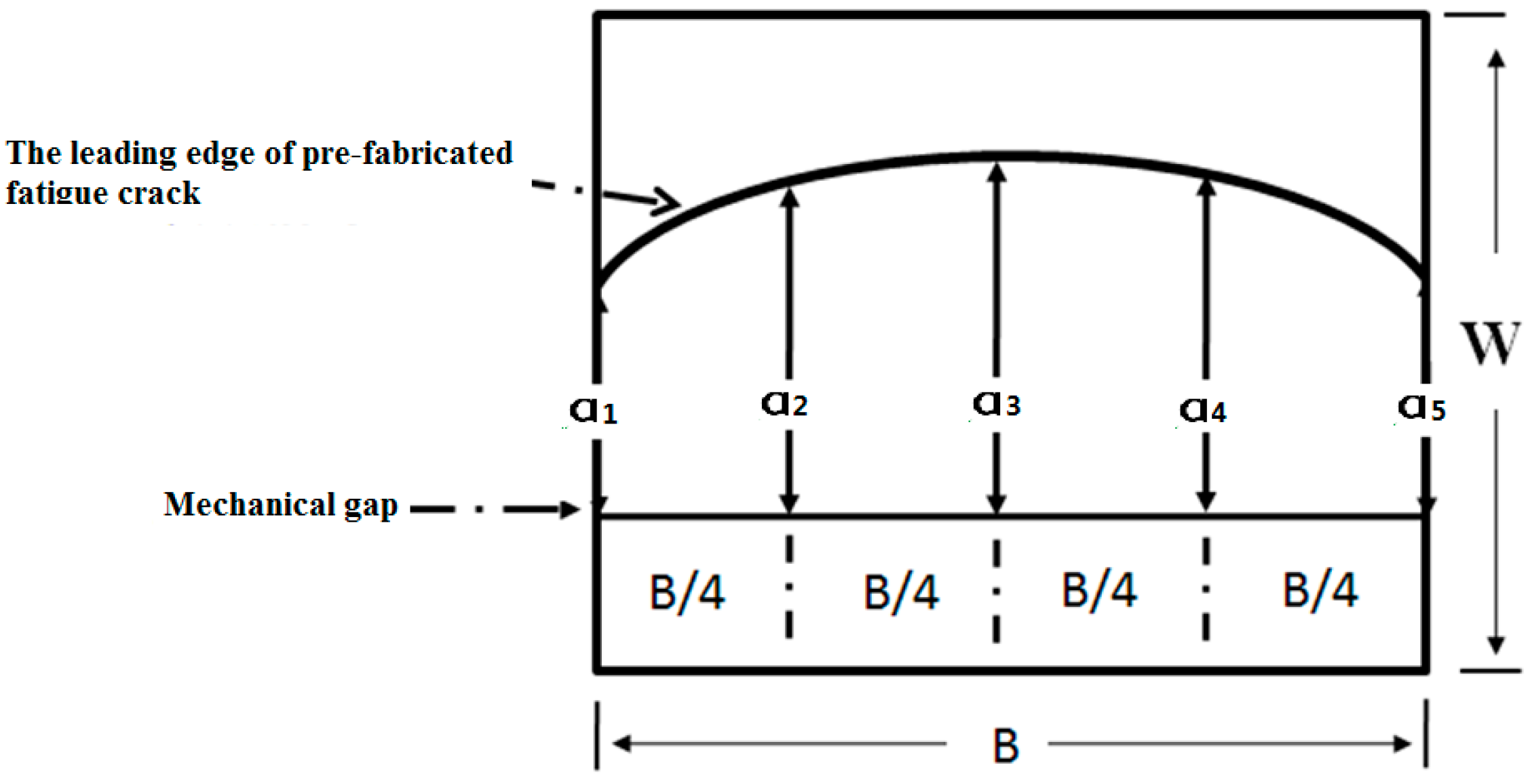
The crack length
ɑ was measured from the fracture, as shown in
Figure 6. The mean value of three readings in the middle was taken as the effective crack length. The crack opening displacement test was carried out on an MTS-880 test machine (MTS, Eden Prairie, MN, USA) at Beihang University. At least three test pieces were selected from each area and tested at room temperature. Firstly, the fatigue crack was pre-fabricated from 7 mm to 9 mm using K-decreasing test. Then, a one-step loading mode was performed until failure. The test load P and opening displacement
V values were collected using the software of the MTS-880 test machine (MTS, Eden Prairie, MN, USA), and then the critical stress intensity factor
KC and the crack tip opening displacement (CTOD) were calculated.
3. Experimental Results and Analysis
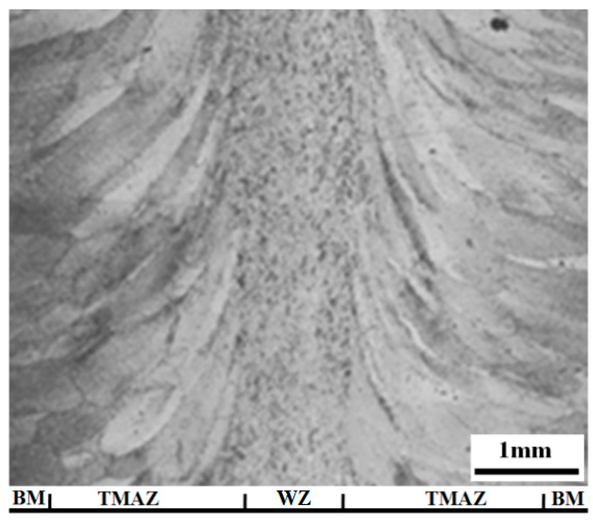
The region of the TC17 linear friction welding joint was divided from left to right into the TC17 base metal, the thermo-mechanically affected zone, and the weld zone of the joint. The width of the WZ was 400 μm, and the entire width of the joint was 3000 μm, as in
Figure 7 that shows the observation surface in the X–Z plane illustrated in
Figure 3 and
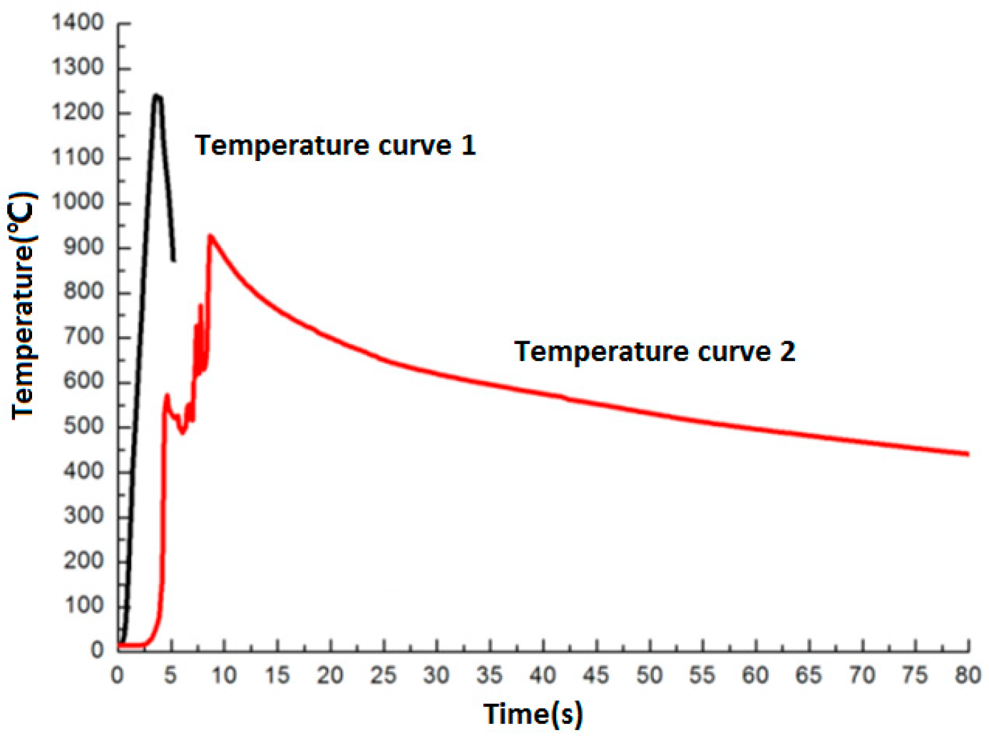
Figure 4. The microstructure around the joint had a significant variation compared to the BM. From the BM to the WZ, the first-order variation of the microstructure was the elongation of β grain along the metal flow direction, and some β grains were separated into a large amount of smaller grains. Meanwhile, the deformation occurred around the boundary of the α phase. At locations closer to the center of joint, the temperature increased gradually. As a result, the deformation degree of the TC17 grain structure increased, and small non-uniform grains formed between the large grains. The grains around the center of the joint were more uniform, with a size of 15 μm. In the linear friction welding process of TC17 titanium alloy, the welding temperature can reach over 1200 °C. As illustrated in
Figure 8, the entire welding process could be completed within 10 s. The heating rate could reach up to 200 °C/s and the cooling rate was higher than 100 °C/s. Thus, the temperature in the joint can decrease from 1200 °C to 800 °C within 3 s.
In the TMAZ, the grains were seriously deformed, having uneven size and very uneven grain boundaries. Moreover, a large number of grains with a size of hundreds of micrometers was observed between the large deformed grains, with residual α phase and metastable β phase in this region. After annealing at 650 °C, no significant changes in the grain size were found. As it can be seen in
Figure 9, the residual α phase in the grains did not change significantly, while the α phase precipitated on the metastable β matrix. The precipitated α phase was disorderly arranged, and its length was about 5 μm, as shown in
Figure 9b.
The WZ of the TC17 linear friction welding joint demonstrated relatively uniform grains with a size of about 15-20 μm, as shown in
Figure 10a. At a faster cooling rate, the as-welded joint retained its TC17 metastable structure. Compare with that in TMAZ, the α phase in the WZ underwent a complete phase transition, and no residual α phase was found in the metastable β grains after cooling. After being annealed at 650 °C, the α phase precipitated on the β matrix and was distributed along some crystallographic orientation with a length of less than 3 μm, as shown in
Figure 10b.
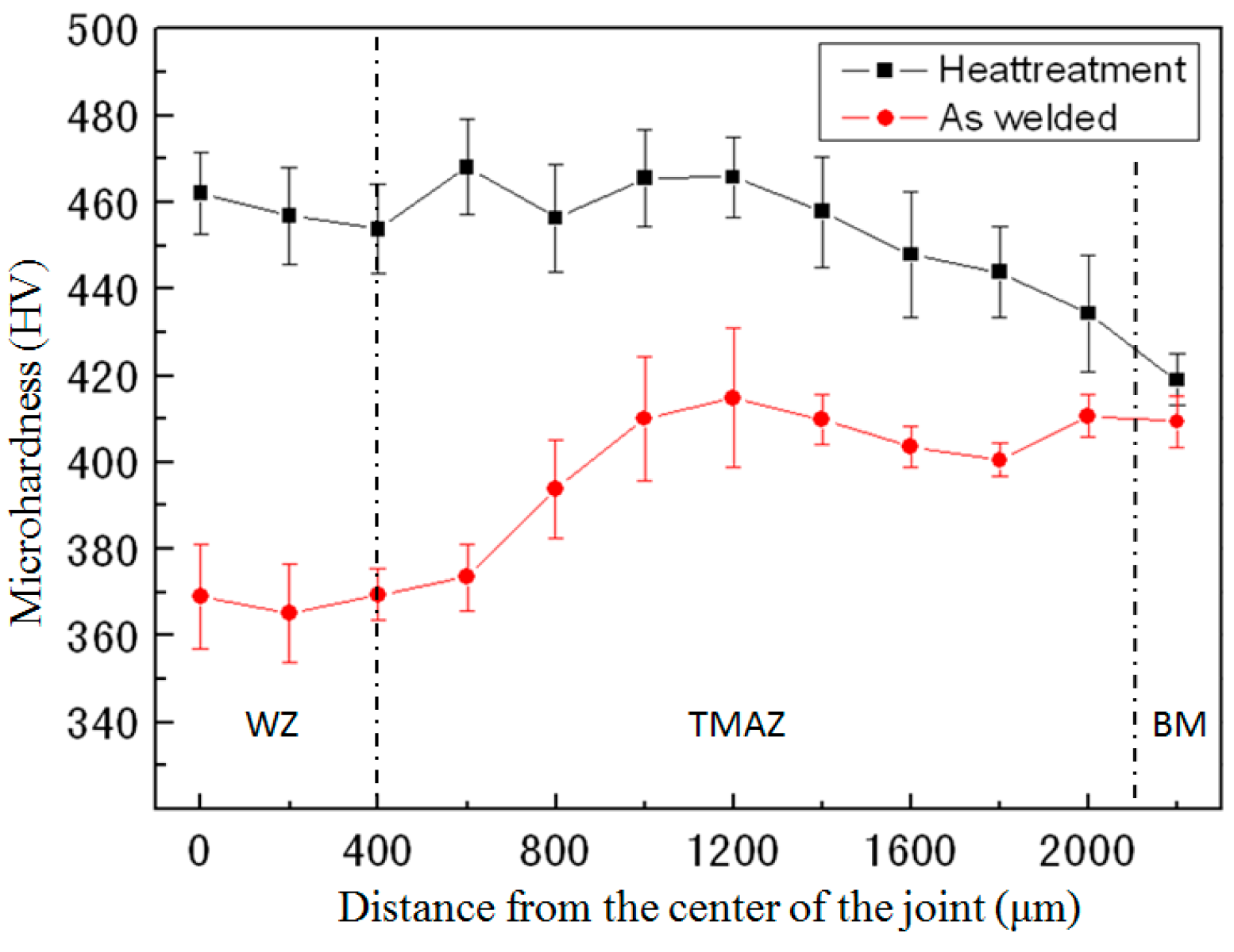
From the base metal to the joint center, the as-welded microhardness of the TC17 linear friction welding joint decreases gradually. The microhardness values of the WZ and the BM ere about 370 HV and 420 HV, respectively, as shown in
Figure 11. After heat treatment, the hardness of the WZ and the TMAZ of the TC17 welded joint increased sharply. No significant difference was found in the microhardness of the two zones, which was around 460 HV, higher than that of the base metal. The order of hardness of the phases appearing in the titanium alloy was followed: ω > α
s (secondary α phase) > α
p (primary α phase) > β > β′ (metastable β phase) [
31,
32,
33,
34]. A large number of equiaxed metastable β phases formed in the weld zone of the as-welded TC17 LFW joint, reducing the hardness. After heat treatment of the joint, the secondary α phase precipitated from the metastable β matrix on the weld zone TC17, which produced a strengthening effect, increased the hardness and led to an increase in microhardness.
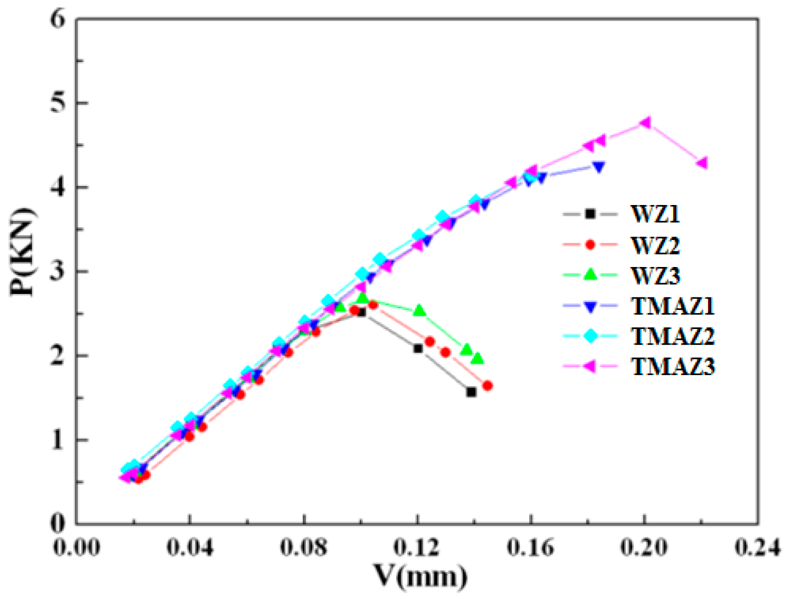
As it can be seen in
Table 2 and
Figure 12, at room temperature, the average crack opening displacement of the TMAZ zone of the joint was 0.0511 mm ± 0.0047 mm, which was much higher than that of the WZ region. Similarly, the minimum crack opening displacement of the TMAZ was also larger than that of the WZ. However, the error range of the crack opening displacement of the WZ was much smaller than that of the TMAZ. At room temperature, the K
C of the TMAZ of the joint was also much higher than that of the WZ. The results indicated that the WZ of the joint center had a poorer resistance against crack propagation.
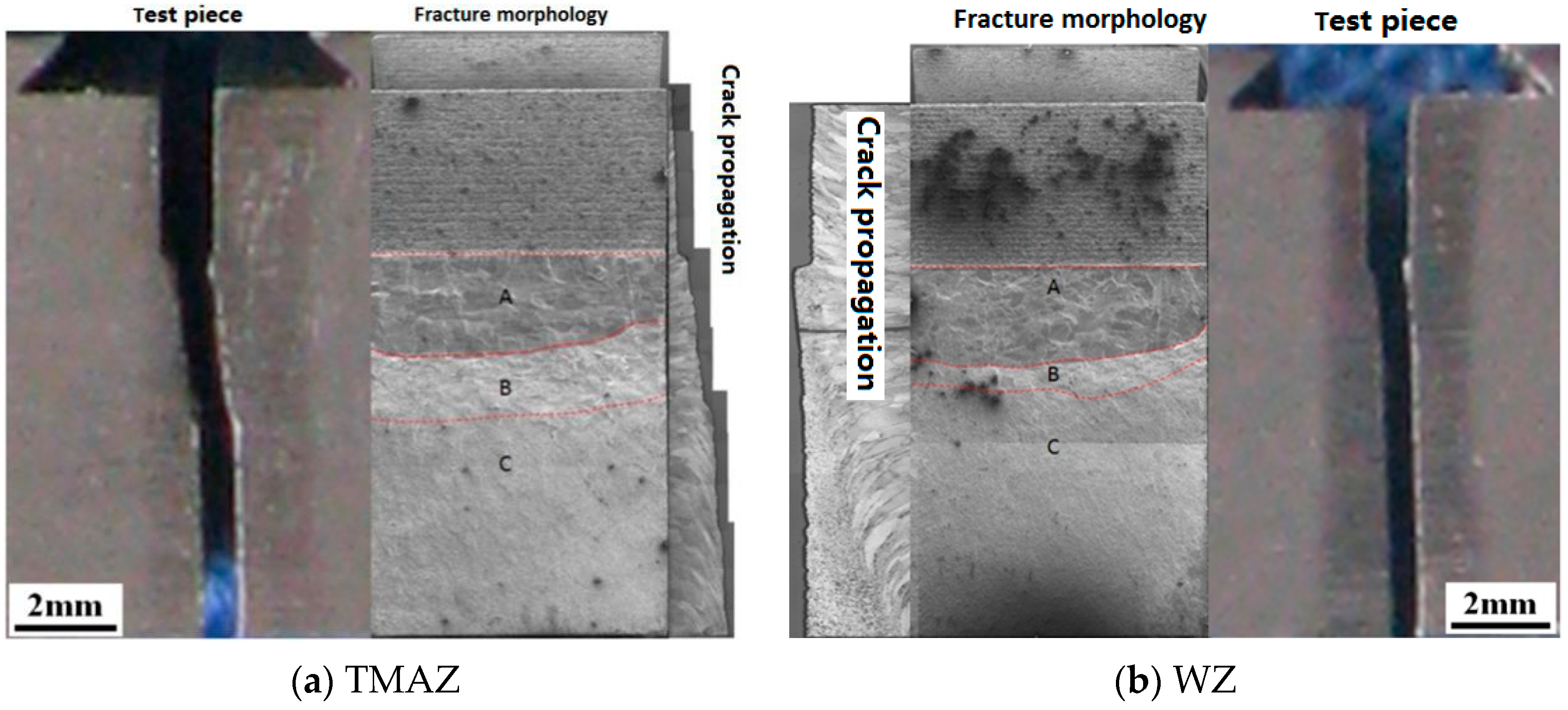
In
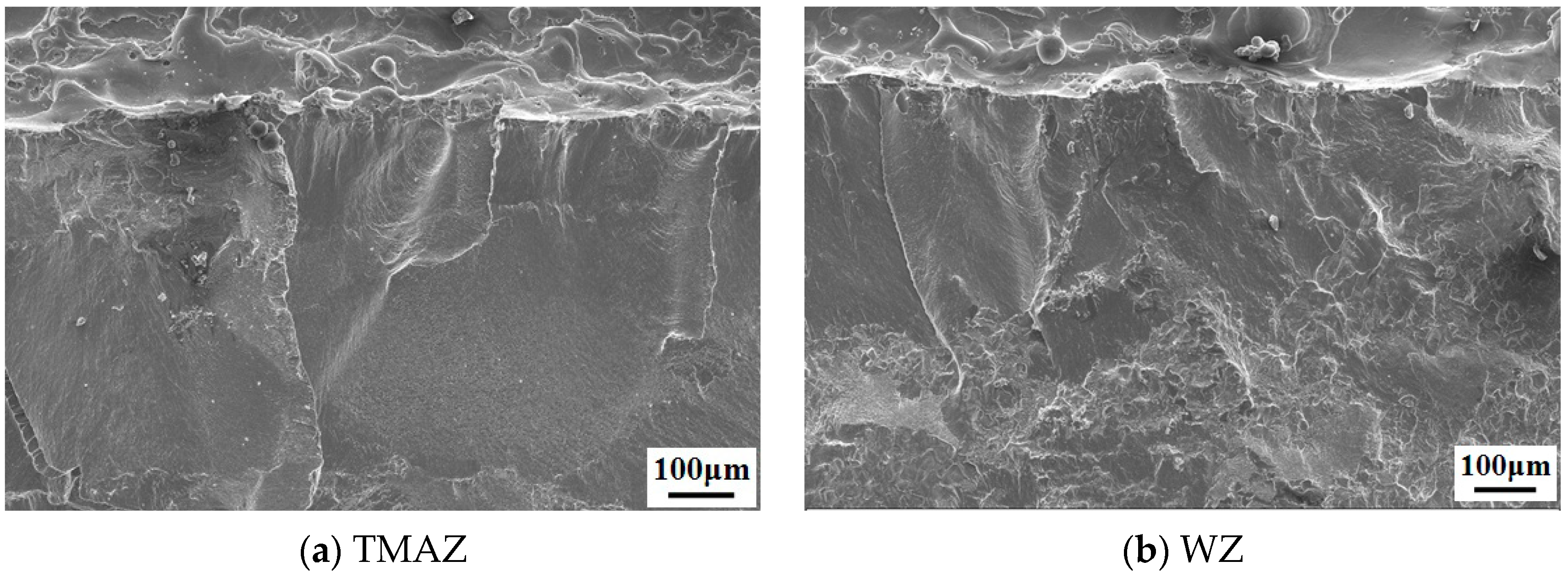
Figure 13a,b, the test piece after the crack opening displacement test is presented. It can be seen that the TC17 test piece having a pre-notched WZ had a crack propagation path smoother than that of the pre-notched TMAZ. In crack propagation, the cracks propagated almost straight and linearly with respect to the notch. The macroscopic crack open displacement fracture of the joint can be divided into three zones: the fatigue crack zone (A), the crack propagation zone (B), and the fracture zone after the test (C). The area of the fatigue crack zone in the TMAZ was equivalent to that formed in the WZ, while the area of the crack propagation zone in the TMAZ was about two times larger than that formed in the WZ. In the TMAZ, the cracks in the fatigue crack zone propagated perpendicular to the direction of the grains and gradually propagated along the elongation direction of the grains. During crack propagation, the cracks formed steps along the direction of the grain boundaries and propagated to the WZ. In the WZ, the cracks in the fatigue crack zone were substantially parallel to the direction of the pre-fabricated notch. The crack propagation path was relatively flat without deviation and was always within the WZ. The comparison between the crack orientations in the TMAZ and the WZ indicated that the cracks were more likely to propagate toward the zone where recrystallization occurred, forming small grains.
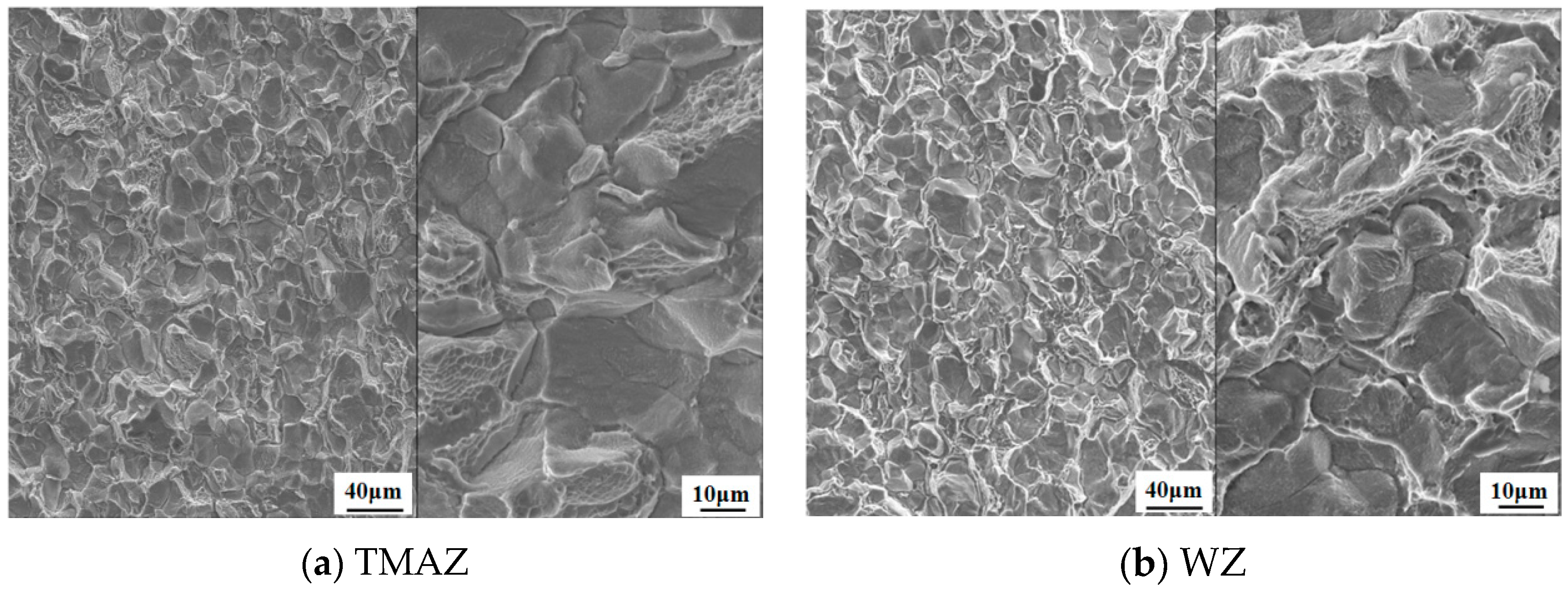
No obvious differences in the crack source in the TMAZ and the WZ were observed, as shown in
Figure 14a,b corresponding to the A areas in
Figure 13.
A significant difference in the morphology of the crack propagation zones of the TMAZ and the WZ was found. As it can be seen in
Figure 15a,b corresponding to the B areas in
Figure 13, the fracture morphology of the crack extension zone of the TMAZ was mainly composed of transgranular and intergranular structures. The transgranular structure mainly consisted of larger coarse-grained structures in the TMAZ with few of equiaxed structures. These equiaxed structures were formed between two larger grains. Transgranular structures were basket-shaped staggered structures with a shallow dimple, which enhanced the resistance against crack propagation. The fracture morphology of the crack propagation zone in the WZ was also composed of transgranular and intergranular fracture structures without larger grains. In the WZ, the grain size was about 20 μm, and the ratio between the transgranular structure and the intergranular structure was about 1:1. The presence of many shallow dimples on the transgranular fracture and a large number of fine grains reduced the resistance against crack propagation.
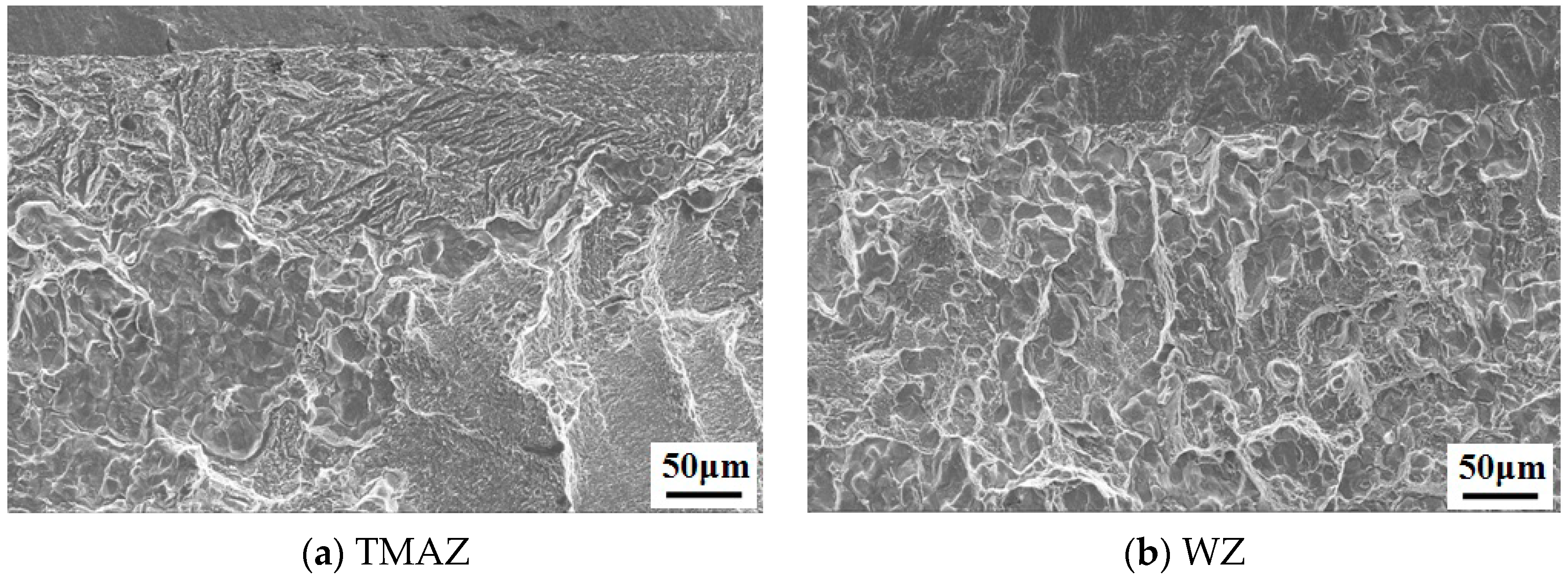
In the fractured zone of the TMAZ and the WZ, no obvious differences in the morphology of the fracture were observed, as shown in
Figure 16a,b corresponding to the C area in
Figure 13. The fractured zone of the TMAZ propagated to the WZ of the joint. The main fracture mode was transgranular fracture, with local intergranular fracture. The fracture indicated that the grain size was around 20 μm.


