Article

A New Empirical Life Prediction Model for 9–12%Cr Steels under Low Cycle Fatigue and Creep Fatigue Interaction Loadings

1
School of Mechanical and Power Engineering, Nanjing Tech University, No.30 Puzhu South Road, Nanjing 211800, China
2
Jiangsu Key Lab of Design and Manufacture of Extreme Pressure Equipment, No.30 Puzhu South Road, Nanjing 211800, China
3
Faculty of Engineering and Architecture, Ghent University, 9000 Ghent, Belgium
4
Institute of Research and Development, Duy Tan University, 03 Quang Trung, Da Nang 550000, Vietnam
5
Soete Laboratory, Ghent University, Technologiepark Zwijnaarde 903, B-9052 Zwijnaarde, Belgium
*
Authors to whom correspondence should be addressed.
Metals 2019, 9(2), 183; https://doi.org/10.3390/met9020183
Submission received: 27 December 2018 / Revised: 24 January 2019 / Accepted: 31 January 2019 / Published: 3 February 2019
(This article belongs to the Special Issue Fatigue Design and Defects in Metals and Alloys)

Abstract

:
Low cycle fatigue (LCF) and creep fatigue interaction (CFI) loadings are the main factors resulting in the failure of many critical components in the infrastructure of power plants and aeronautics. Accurate prediction of life spans under specified loading conditions is significant for the design and maintenance of components. In the present study, various LCF and CFI tests are conducted to investigate the effects of temperature, strain amplitude, hold time and hold direction on the fatigue life of P92 steel. To predict fatigue life under different experimental conditions, various conventional life prediction models are evaluated and discussed. Moreover, a new empirical life prediction model is proposed based on the conventional Manson-Coffin-Basquin (MCB) model. The newly proposed model is able to simultaneously consider the effects of temperature, strain amplitude, hold time and hold direction on predicted life. The main advantage is that only the known input experimental parameters are required to perform the prediction. In addition to the validation made through the experimental data of P92 steel conducted in the present paper, the model is also verified through numerous experimental data reported in the literature for various 9–12% Cr steels.

1. Introduction

Many critical engineering components used in aeronautics, power generation plants and the petrochemical industry inevitably suffer from high temperature low cycle fatigue (LCF) and creep fatigue interaction (CFI) damage due to the complicated temperature transients and increasing requirements of operational flexibility [1,2]. In practice, LCF and CFI have been recognized as the main failure contributors in the mentioned industry areas. Consequently, proper life prediction of LCF and CFI loadings is of great significance to the design of components in order to minimize the risk of unplanned standstills in plants. However, macroscopically, it has been demonstrated that LCF and CFI lifetime are not only related to the type of material, but are also affected by the interactive effects of temperature, strain amplitude, hold conditions and environmental corrosion [3,4,5]. Regarding Eurofer 97 steel tested in high vacuum, there is no significant effect of test temperature ranging from 150 °C to 550 °C on fatigue life at the same strain amplitude. However, a dramatic reduction in life due to the introduction of hold time was observed at low imposed strain amplitudes [6]. In Haynes 188 alloy, hold-time effect was strain amplitude dependent and increased with a decrease in strain amplitude [7]. Moreover, hold direction had different effects on different materials. For example, the tensile hold period is more deleterious than the compressive hold period for 316L stainless steel, while 9–12% Cr steels had the opposite behavior [8,9,10]. Microscopically, the life span is closely related to the microstructural evolutions of various materials [3]. Concerning high Cr martensitic steels, an increase in martensitic lath width, growth of subgrain size, reduction of dislocation density and coarsening of numerous precipitates are typical factors affecting the life span [3,11,12]. These complicated damage mechanisms make it difficult to accurately predict the life spans for LCF and CFI loadings. Therefore, this topic deserves further investigation, despite numerous papers have been dedicated to this topic over the past decades.
9–12% Cr steels and their modified versions have been extensively used as structural materials of ultra-supercritical power plants, which demonstrate high thermal efficiency and low CO2 emissions due to extremely high operational temperatures and pressures. In addition, 9–12% Cr steels are also considered as good candidate materials for application in reactor pressure vessels of Generation IV nuclear plants [13]. Since the increasing requirements of flexible operation leads to LCF and CFI damage in modern power plants, it is significant to understand the effect of loading conditions on the LCF and CFI lives. Moreover, a generalized life prediction model that is able to capture the different types of loading effects is valuable. In the present investigation, existing life prediction models for LCF and CFI loadings are first briefly reviewed. Then, in the experimental part, a series of LCF and CFI tests at various test conditions are conducted to investigate the effects of strain amplitude, temperature and hold condition on the life span of P92 steel. In the following part, three conventional life prediction models are employed to predict life. Finally, based on the experimental results and the conventional Manson-Coffin-Basquin (MCB) model, a new empirical life prediction model is proposed and validated by the obtained experimental data in the present paper and by the extensive experimental data reported in the literature.

2. Brief Review of the Life Prediction Models

In the literature, there are abundant fatigue life prediction models. Review papers related to this topic come out frequently [14,15,16,17,18,19]. In accordance with the reported approaches, these models can be mainly divided into two main categories. The first is prediction models based on fracture mechanics, while the second is models based on cumulative damage theories. All models try to properly take the effects of the material, structure, loading and environment into account to give a precise life prediction. Since these factors affect the fatigue life interactively rather than individually, it makes fatigue life predictions really complex. For example, the life predictions under LCF and CFI loadings are complicated due to the interactions among fatigue, creep and oxidation [20]. In recent years, the life estimations under LCF and CFI loadings were very popular [1,21,22]. Based on the aforementioned two categories, the number of investigations using fracture mechanics are comparatively low compared to those adopting the cumulative damage models. It was extensively recognized that crack propagation occupied most of the lifetime under LCF and CFI loadings [23]. As a consequence, most of the fracture mechanics models focused on the process of fatigue crack propagation [24]. Ainsworth et al. [25] integrated the creep crack growth and fatigue crack growth per cycle to calculate the remaining life of a component with pre-existing defects, which was subjected to CFI loadings. Wen et al. [26] simulated model-I crack growth under CFI loading, taking into account the damage induced by grain boundary cavitation and by solute diffusion. Many of other researchers [27,28,29] also investigated the effect of high temperature oxidation on creep fatigue crack propagation and life. Although the majority of the lifetime is spent on crack propagation, it is still critically important to investigate the crack nucleation or initiation from the point of view of a comprehensive understanding of fatigue failure mechanisms. Moreover, crack nucleation or initiation is more related to the material microstructure itself; thus, investigation on crack initiation can provide guidance to optimize the material design to improve the material fatigue endurance [30]. Compared to fracture mechanics-based models, cumulative damage models can estimate the total fatigue life in a good way [31]. Furthermore, the latter are normally easy to use in engineering applications. Consequently, even though cumulative damage models appeared early, they are still popular in the field of life prediction under LCF and CFI loadings. Cumulative fatigue damage theories can be briefly divided into four types of approaches, i.e., stress-based, strain-based, energy-based and continuum damage mechanics. The Coffin-Manson equation, which belongs to the strain-based approach, is one of the most frequently-used models to predict LCF life spans. Zhu et al. [32] developed a generalized frequency separation-strain energy damage model based on the frequency-modified Manson-Coffin equation, which can be extended to the application of stress-controlled CFI tests. In the scope of continuum damage mechanics, Chaboche [33] have already given a comprehensive review of constitutive models that can also be used to predict life. Moreover, plenty of conventional cumulative fatigue damage and life prediction theories can be found in the review carried out by Fatemi and Yang [34]. Although comprehensive investigations have been performed, this research is still open, due to the complicated interactions among various factors, and is of great significance to the safety of critical engineering components serviced at elevated temperatures. To provide a relatively accurate and easy use prediction model for engineering applications, and to avoid the complex physical explanation of interactive damage mechanisms, a new empirical LCF and CFI life prediction model is proposed, and an improved prediction accuracy is expected in the present study.

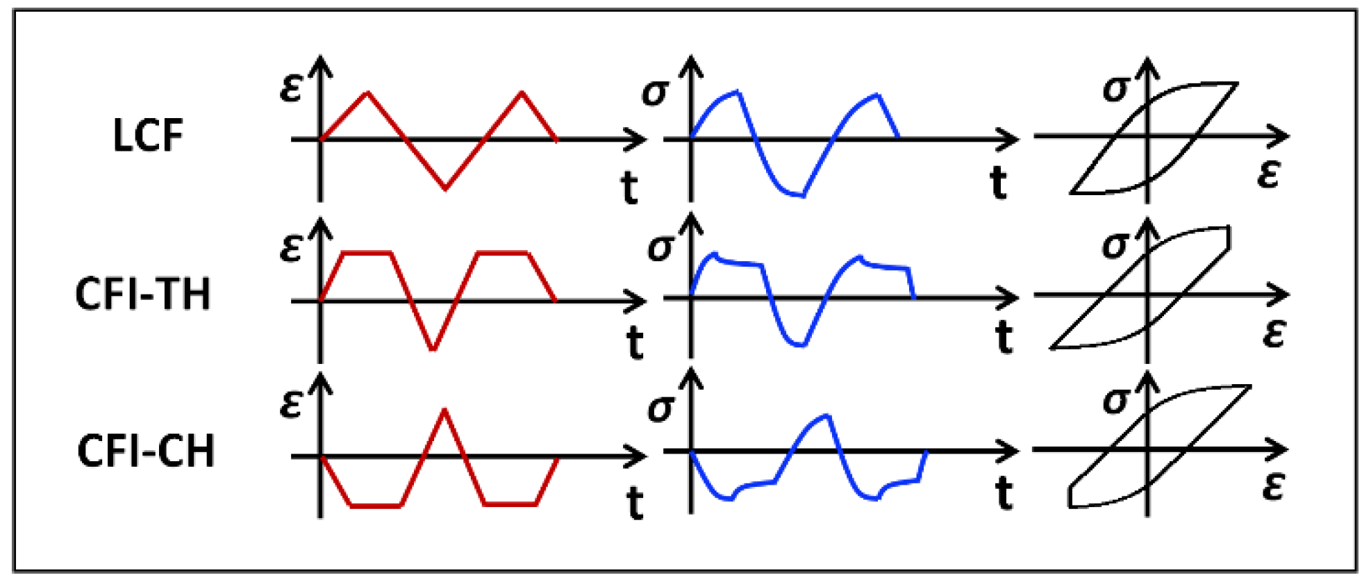
3. Experimental Description

ASME-grade P92 pipe with an outer diameter of 105 mm and a wall thickness of 24 mm was used in this study. The pipe was supplied in normalized and tempered conditions. The chemical composition in wt % is C: 0.106, Mn: 0.361, Si: 0.235, P: 0.017, S: 0.0081, Cr: 9.18, Mo: 0.368, V: 0.182, N: 0.061, Ni: 0.108, Al: 0.0059, Nb: 0.078, W: 1.85 and B: 0.0022. Cylindrical fatigue specimens with 8 mm gauge diameter and 25 mm gauge length were extracted from the pipe axial direction and along the same circle to avoid the heterogeneous microstructure through the wall thickness. A series of fully-reversed LCF tests at different temperatures ranging from room temperature (20 °C) to 650 °C and at various strain amplitudes varying from 0.2% to 0.8% were conducted in accordance with the ASTM E2714 standard. Regarding CFI tests, different hold periods ranging from 1 to 60 min were imposed on the maximum tensile strain or maximum compressive strain of LCF tests at 0.4% strain amplitude with a temperature of 600 °C. Schematic waveforms of LCF tests and CFI tests with tensile hold (CFI-TH) or compressive hold (CFI-CH) are presented in Figure 1. All tests were carried out in air with axial strain control at a constant strain rate of 1 × 10⁻³ s−1. Test conditions of each specimen are listed in Table 1. An electrical fatigue test setup RPL100 (Sinotest Equipment Co., ltd. Changchun, China) equipped with a resistance heating furnace was utilized. During the test period, the specimen temperature was measured by three K-type thermocouples, and the temperature stability was controlled within ±2 °C. Deformation in the specimen gauge length was measured by a high temperature extensometer produced by Epsilon. Before the tests, all specimens were mechanically polished to prevent premature cracks from initiating at machined traces on the specimens’ surfaces.

4. Experimental Results and Discussion

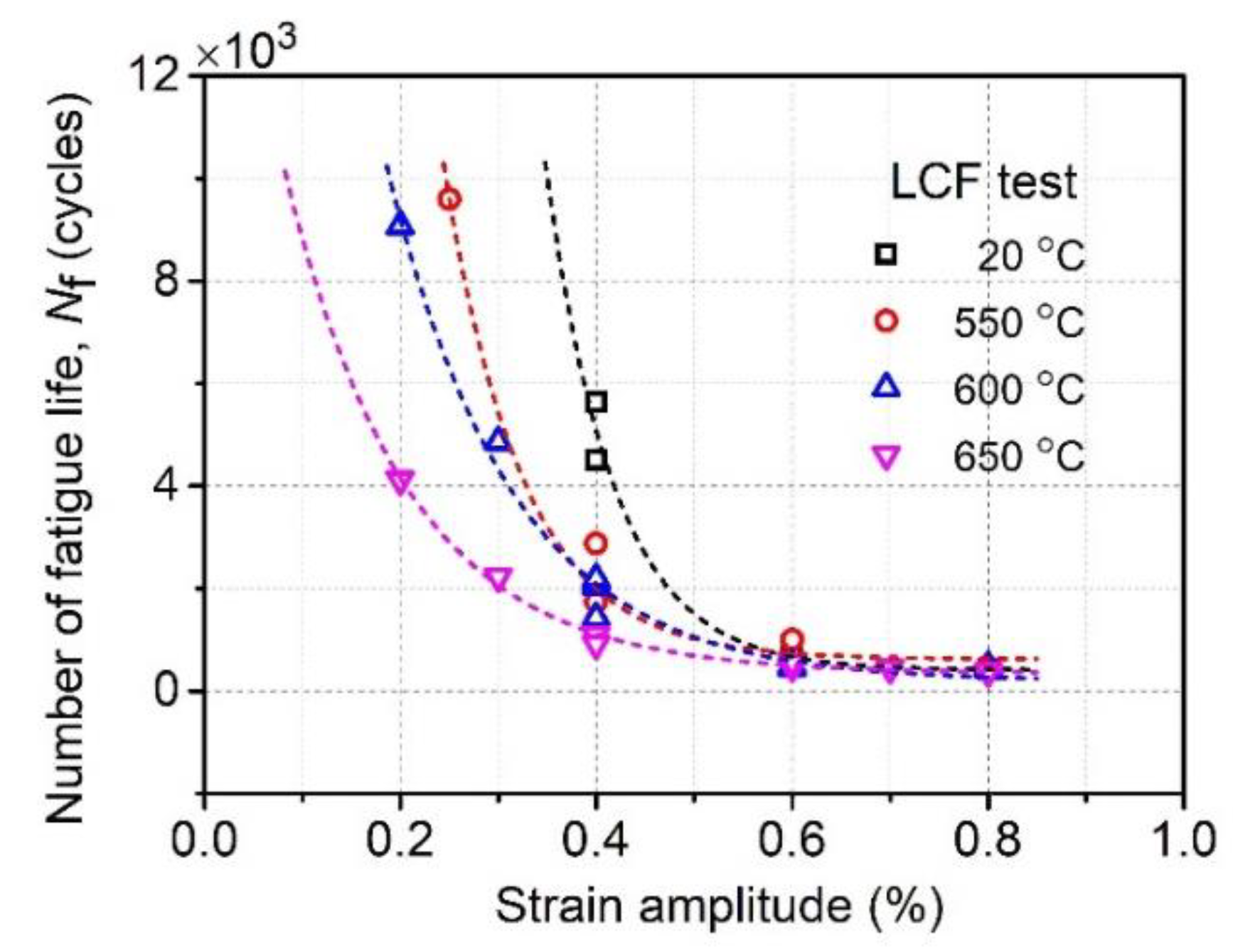
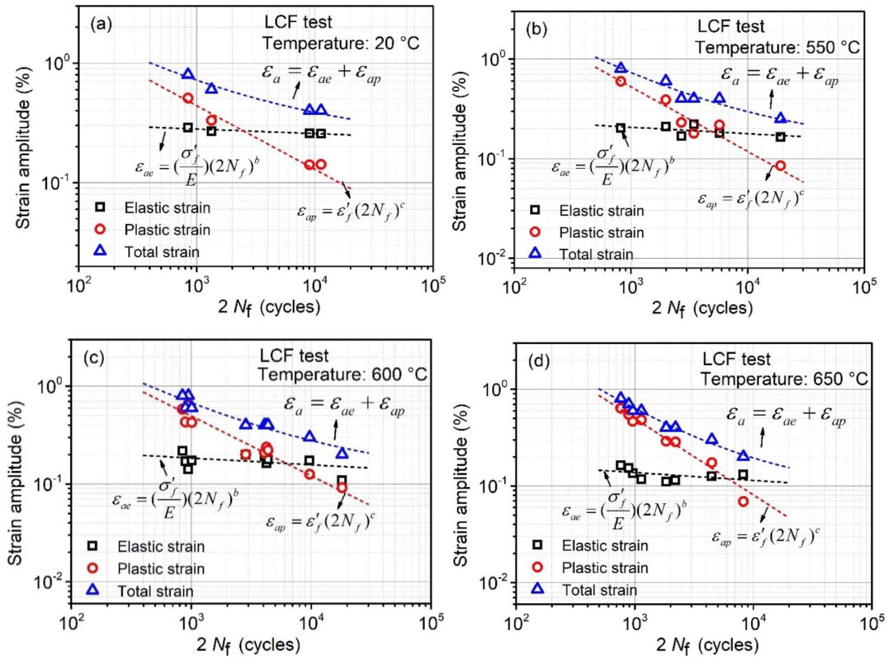
4.1. Effect of Strain Amplitude and Temperature

Commonly, cycle number of fatigue life under LCF loading is strain amplitude- and temperature-dependent [35]. Strain amplitude mainly determines the plastic strain level for each cycle. The relationship between plastic strain and fatigue life can be described by the well-known Manson-Coffin equation [36,37]. Temperature effect on the fatigue life is the result of accelerating microstructure damage and high temperature corrosion such as oxidation [38]. Figure 2 depicts the relationships among fatigue life, temperature and strain amplitude of P92 steel. Regarding the strain amplitude influence, fatigue life decreases with an increasing strain amplitude. The life reduction is dramatic at low strain amplitudes, while it becomes saturated as the strain amplitude exceeds 0.6%. In addition, at high strain amplitudes, the saturated value of fatigue life seems to remain constant, irrespective of temperature, which indicates that plastic deformation dominates the fatigue life. Similarly, temperature also plays a crucial role in fatigue life determination at low strain amplitudes. For example, when the temperature increases from 600 °C to 650 °C at 0.2% strain amplitude, the fatigue life is decreased by 54%. The evident effect of temperature at low strain amplitudes may result from the high temperature oxidation, as oxidation is the function of exposure time and environment temperature [39]. At low strain amplitudes, the fatigue lifetime is much longer than that of high strain amplitudes, so that the specimen surface has adequate time to become oxidized. Moreover, high temperatures accelerate the formation of an oxidation layer on the specimen surface, which is brittle and is easily cracked during cyclic deformation. Then, the cracked oxidation layer favors the fatigue crack initiation, and thus, the fatigue life at low strain amplitude is reduced at an increasing test temperature. The explanation here can also be verified by Marmy’s [6] research, in which the conclusion that temperature does not significantly affect the LCF life of Eurofer 97 when the tests were conducted in high vacuum from 150 °C to 550 °C was drawn.
The total strain imposed on the specimen is the summation of elastic and plastic strains. The Basquin equation [40] is widely used to describe the relationship between elastic strain and fatigue life, which is normally suitable to high cycle fatigue loading. As for the relationship between plastic strain and fatigue life, the well-known Manson-Coffin law is frequently used. Figure 3 illustrates the variation behavior of fatigue life at different elastic strain amplitudes and plastic strain amplitudes at different temperatures, i.e., ranging from 20 °C to 650 °C. It is shown that the fatigue life presents good linear relationships with elastic strain and plastic strain in the logarithmic axis, respectively. Accordingly, the fatigue life of P92 steel under LCF loading can be predicted by the combination of Basquin and Manson-Coffin equations, which are discussed in Section 5.1.

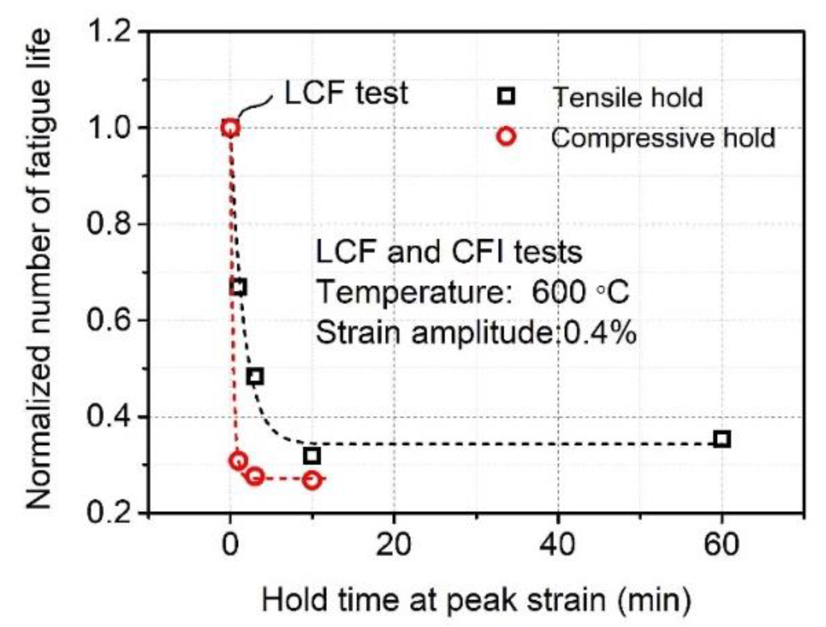
4.2. Effect of Hold Time and Hold Direction

It has been widely recognized that the introduction of a peak strain hold during LCF loading will lead to additional creep deformation [38]; thus, it is called CFI loading. For most ferritic steels, the existence of hold period reduces the fatigue life due to the combined effects of non-zero mean stress, additional creep damage, surface oxidation and accelerated microstructure evolution [38,41]. Figure 4 shows the effect of hold time and hold direction on the fatigue life of P92 steel at 600 °C. The CFI life is normalized by the LCF life at the same strain amplitude of 0.4%. It is observed that tensile hold time plays a significant role in reducing the fatigue life, as the hold time is within 10 min. However, the degradation behavior becomes saturated as tensile hold time exceeds 10 min. In contrast, the introduction of a compressive hold time yields additional degradation of life. In addition, a similar saturated behavior of fatigue life reduction is observed for compressive hold condition as well, but this behavior comes earlier than that of tensile hold. With respect to tensile hold conditions, 10 min is needed to achieve the saturated behavior, while in a compressive hold state, only 3 min is required. In the saturated stage, the fatigue life is decreased by 65% and 75% for tensile hold and compressive hold, respectively. An explanation of the observed phenomena is given in our previous investigation [10].
To elucidate the variation of CFI life at different elastic strain amplitudes and plastic strain amplitudes, CFI data is added in Figure 3c, as shown in Figure 5. It can be observed that CFI data does not obey the linear relationship. Consequently, the commonly used Manson-Coffin and Basquin equations cannot justify fatigue life predictions under CFI loading, and thus, modifications to them are required.

5. Application of Existed Life Prediction Model

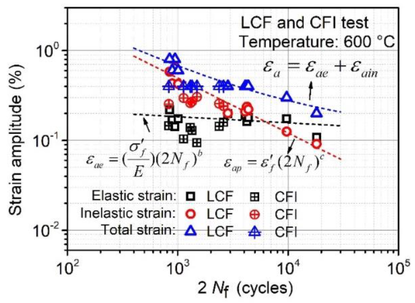
5.1. Coffin-Manson-Basquin Model

In past decades, although numerous fatigue life prediction models were developed, the classical Coffin-Manson-Basquin (MCB) model has been continuously used and investigated for plenty of materials because of its simplicity and easy application. The MCB model is the combination of Coffin-Manson relationship [36,37] and Basquin relationship [40]:
ε a = ε a e + ε a p = ( σ f E ) ( 2 N f ) b + ε f ( 2 N f ) c
where εa is the total strain amplitude, which is composed of elastic strain amplitude, εae, and plastic strain amplitude, εap. Nf is the fatigue life. In the model, E is the elastic modulus, σ’f is the fatigue strength coefficient, b is the fatigue strength exponent, ε’f is the fatigue ductility coefficient and c is the fatigue ductility exponent. It is worth mentioning that all the parameters in the MCB model are temperature dependent. Table 2 lists all the MCB parameters, which are determined by fitting the LCF experimental data at different temperatures. In accordance with the determined parameters, the relationships between strain amplitude and LCF life at various temperatures can be well described, as depicted by the dashed lines in Figure 3. Additionally, the fatigue life can then be predicted by Equation (1) with a specified total strain amplitude. To evaluate the prediction capability of MCB model, a comparison between the experimental results listed in Table 1 and the MCB model predicted lives under LCF and CFI loadings is shown in Figure 6a. It is observed that all the predicted LCF lives are within the 2-scatter band, yet the predicted CFI lives go outside of the scatter band. In addition, the ratio between experimental life, Nfe, and predicted life, Nfp, is proposed to check whether the predicted results are conservative (ratio > 1) or non-conservative (ratio < 1). Figure 6b shows that all the predicted CFI life is non-conservative, which is dangerous for engineering applications. Moreover, the non-conservative predicted LCF life at 0.2% strain amplitude can be detected due to the different failure mechanisms at elastic deformation dominated fatigue loading. The relatively worse predicted CFI lives is educible because the MCB model does not distinguish the additional degradation caused by the hold time. Consequently, a modified version of MCB model should be proposed to take the effect of the hold time into consideration.

5.2. Energy Based Model

Since fatigue failure is the result of micro or macro cyclic plastic strain [30], plastic strain energy plays a crucial role in the fatigue life determination [42]. Theoretically, plastic strain energy density can be physically interpreted as distortion energy of a volume element [43]. Its numerical value is equivalent to the area of stress-strain hysteresis loop for the uniaxial fatigue tests. The relationship between fatigue life and plastic strain energy density can be described by the following Morrow equation [44]:
W P = m ( N f ) n  
where Wp is the plastic strain energy density at stabilized cycle, m and n are fatigue coefficient and exponent, respectively. The significance of the energy based (EB) model is that Wp can unify different types of loadings such as ratchetting, creep-fatigue, and so on. Therefore, it is possible to use the Morrow model to predict the CFI life. To determine the parameters m and n, LCF and CFI test data at 600 °C listed in Table 1 are utilized to perform the regression analysis, then m = 211 and n = −0.64 are identified. Figure 7 shows a comparison between experimental and predicted results. It can be observed that nearly all of the predicted lives are within the 2-scatter band, except that of CFI-CH loading. In addition, Figure 7b indicates that predicted result of CFI-CH loading lies on the non-conservative side.

5.3. Frequency Separation Model

The frequency separation (FS) model proposed by Coffin [45] was especially developed for the consideration of time dependent damage during fatigue loadings. It differentiates the time dependent tensile and compressive damage by introducing the tension-stage frequency and compression-stage frequency into the Coffin-Manson relationship. In this way, the FS model is expressed as:
N f = Z ε a p q ν t w ( ν c ν t ) k
where υt and υc are tension-stage frequency and compression-stage frequency, respectively. υt is the reciprocal of the time in tensile stage of the loading waveform as shown in Figure 1. υc is similar, but the tension-stage time is replaced with the compression stage time. Z, q, w, k are temperature dependent material constants, which can be determined by fitting Equation (3) to known test results. For P92 steel tested at the temperature of 600 °C, Z = 700, q = −1.359, w = 0.423, k = 0.354 are identified by the regression analysis of test data listed in Table 1. With the known material parameters, fatigue life can then be predicted. Figure 8 shows a comparison between predicted results using FS model and the experimental data. Compared to Figure 7a, better predicted capacity of FS model can be achieved for the CFI data, as shown in Figure 8a. Moreover, Figure 8b indicates that the predicted results of CFI-CH test become conservative.

6. Modified MCB Model

Comparisons among the MCB, EB and FS models show that MCB model is the most convenient life prediction model because the input parameter is the known total strain amplitude, εa, as shown in Equation (1). However, apart from the known υt and υc in FS model, the EB and FS model additionally requires the experimentally-determined parameters, plastic strain energy density, Wp, shown in Equation (2) and plastic strain amplitude, εap, shown in Equation 3, respectively. Therefore, among these models, the MCB model is the true life prediction model, and has the potentiality to construct fatigue curves of total strain amplitude versus life as a function of temperature and hold conditions, which could be used as a basis for the design of components.

6.1. Consideration of Effect of Temperature and Hold Condition

Temperature is shown to greatly affect the LCF life at low strain amplitude, as illustrated in Figure 2. As a consequence, the material parameters in the MCB model are temperature dependent, as listed in Table 2. Moreover, it is found that introduction of hold period reduces the fatigue life and compressive hold condition causes severer damage than that of tensile hold condition. Therefore, it is reasonable to introduce two separable life damage coefficients caused by the tensile hold period and compressive hold period. Accordingly, to consider the effects of temperature and hold condition, the conventional MCB model is modified as:
ε a = ε a e + ε a p = σ f ( T * ) E ( 2 N f D t D c ) b ( T * ) + ε f ( T * ) ( 2 N f D t D c ) c ( T * )
where σ’f (T*), b (T*), ε’f (T*), c (T*) are temperature dependent material parameters, Dt and Dc are damage coefficients caused by tensile hold and compressive hold, respectively, and T* is the homologous temperature and is expressed as:
T * = T T r e f T m T r e f
where T is the current temperature (unit °C), Tm is the melting temperature and Tref is the reference temperature. For 9Cr-1Mo steel, Tm is 1530 °C [46]. The reference temperature is defined as 20 °C in the present study. By fitting the determined material parameters listed in Table 2, the relationship between the material parameters and the temperature can be represented as:
σ f ( T * ) = τ 1 T * 3 + φ 1 T * 2 + ω 1 T * + γ 1  
b ( T * ) = τ 2 T * 3 + φ 2 T * 2 + ω 2 T * + γ 2  
ε f ( T * ) = τ 3 T * 2 + φ 3 T * 2 + ω 3 T * + γ 3
c ( T * ) = τ 4 T * 3 + φ 4 T * 2 + ω 4 T * + γ 4
where τi (i = 1,2,3,4), φi (i = 1,2,3,4), ωi (i = 1,2,3,4), γi (i = 1,2,3,4) are fitting parameters.
In accordance with the CFI tests results achieved in this study, it is found that degradation of fatigue life introduced by peak strain hold is time dependent, as shown in Figure 4. Additionally, experimental results of P91 steel at 550 °C reveal that the degradation is related to the strain amplitude, which shows that the impact of hold time on fatigue life is more pronounced at lower strain amplitudes [47]. Moreover, it was reported that temperature played a role in the CFI life reduction [39]. This can also be achieved through the comparison between the experimental data of the present study and the reported results of Fuhrer’s investigation [47]. In summary, the proposed life damage coefficients Dt and Dc should depend on hold time, strain amplitude and temperature, and the three factors may have interactive effects on the fatigue life. To quantify the complicated influence, Dt and Dc are expressed in the following way:
D t = α t β t t t exp ( g t T * )   exp ( h t ε α ) + ( 1 α t )
D c = α c β c t c exp ( g c T * )   exp ( h c ε α ) + ( 1 α c )
where exp-function is ex, αt and βt are parameters related to tensile hold time, tt is the tensile hold time (min unit), gt and ht are parameters related to temperature and strain amplitude of CFI-TH tests, respectively. Similarly, αc, βc are parameters related to compressive hold time, tc is the compressive hold time (min unit), gc and hc are parameters related to temperature and strain amplitude of CFI-CH tests, respectively. It is worth noting that according to the expressions of Dt and Dc, the MCB model (Equation 1) is a particular case of the modified MCB model (Equation 4) when neither of hold time (tt = 0, tc = 0) exist.

6.2. Material Parameters Determination and Calibration

All the parameters in the modified MCB model can be divided into two categories. The first is LCF life-dependent material parameters, τi (i = 1,2,3,4), φi (i = 1,2,3,4), ωi (i = 1,2,3,4), γi (i = 1,2,3,4), which can be identified from LCF lives at different temperatures. The second is CFI life-dependent parameters, αt, βt, gt, ht, αc, βc, gc, hc, which are identified from CFI lives at various hold conditions, i.e., different hold time, different strain amplitudes and different temperatures. Based on the proposed equations listed from Equation 4 to Equation 11, all parameters are determined by regression analysis in the following procedures. Firstly, parameters τi (i = 1,2,3,4), φi (i = 1,2,3,4), ωi (i = 1,2,3,4), γi (i = 1,2,3,4) are determined by fitting the Equations. 6–9 to the known values listed in Table 2. Secondly, hold time dependent parameters αt, βt, αc, βc, are determined with the regression analysis of 600 °C CFI test data listed in Table 1 at different tensile hold time and compressive hold time. Thirdly, ht, hc are identified from the CFI tests at different strain amplitudes. CFI test data reported by Fuhrer [47] is used to perform the regression analysis in this step, as listed in Table 3. Finally, gt, gc are determined by the combined CFI test data at different temperatures listed in Table 1 and Table 3. All determined parameters of modified MCB model are listed in Table 4 and Table 5.
To calibrate the determined parameters, Figure 9a shows the comparison between the modified MCB predicted life and the experimental life listed in Table 2. It is observed that all the predicted results are within the 2-scatter band, and most of them are even located in the 1.5-scatter band. Moreover, Figure 9b indicates that predicted CFI lives randomly distribute at both conservative and non-conservative sides. It should be noted that the obvious advantage of the modified MCB model is that only the test parameters (temperature, strain amplitude, hold time, hold direction) are required for the life prediction, while the EB and FS model is really limited due to the experimentally-determined plastic strain energy density and plastic strain amplitude at the stabilized cycle. Therefore, it is easy to use the modified MCB model to construct fatigue curves of strain amplitude versus life with the considerations of temperature and various hold conditions. Table 6 lists the required parameters and the prediction capability for each prediction model used in the present study. From Figure 9a, it should be observed that only the predicted fatigue data at different temperatures and different hold time are calibrated; however, the CFI data at other temperatures and strain amplitudes listed in Table 3 needs calibration as well, as shown in Figure 10. It is worth mentioning that the LCF data and the CFI test with symmetric tensile and compressive hold periods (CFI-TCH) data shown in Figure 10 are not used to identify the material parameters; thus, the lives of LCF and CFI-TCH test are predicted values. The locations of predicted LCF and CFI-TCH lives shows a good predictive capability of the newly modified MCB model.

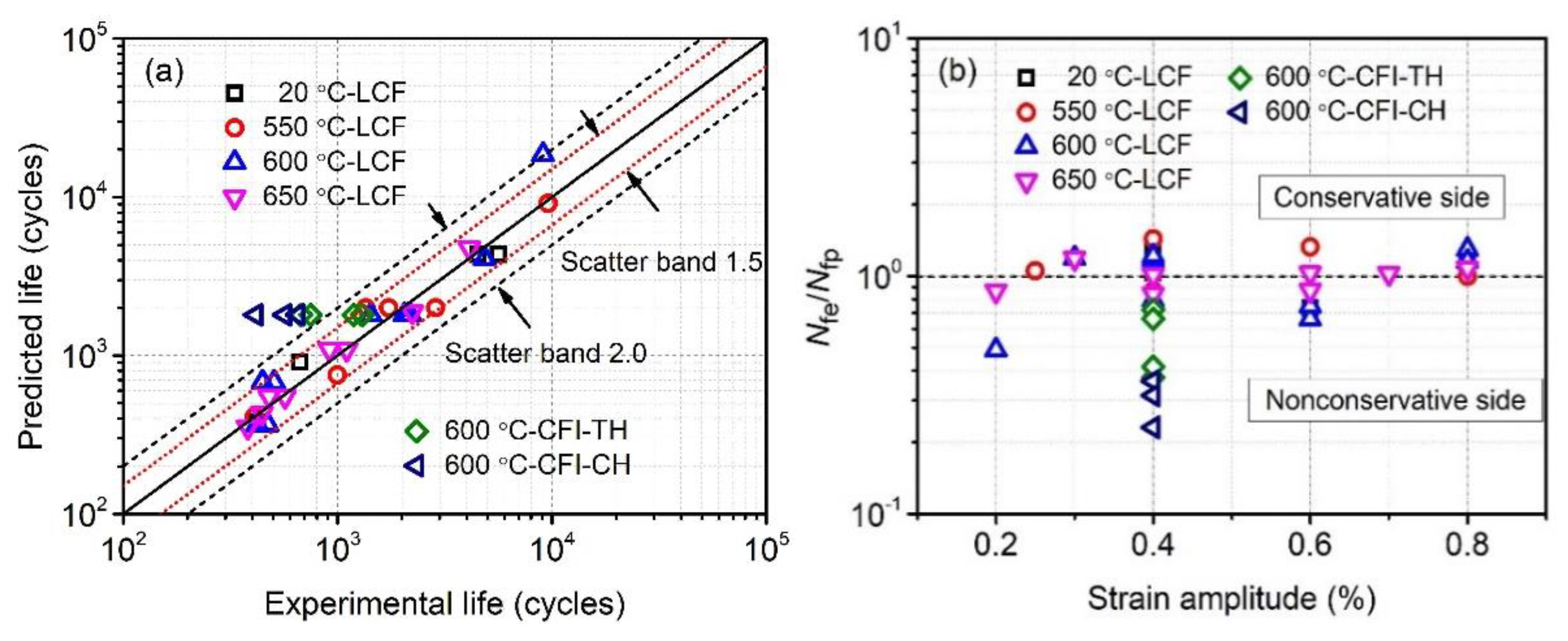
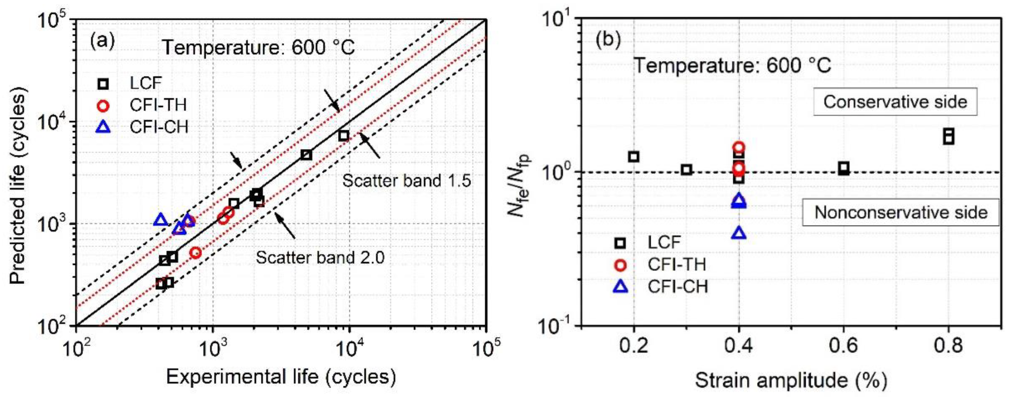
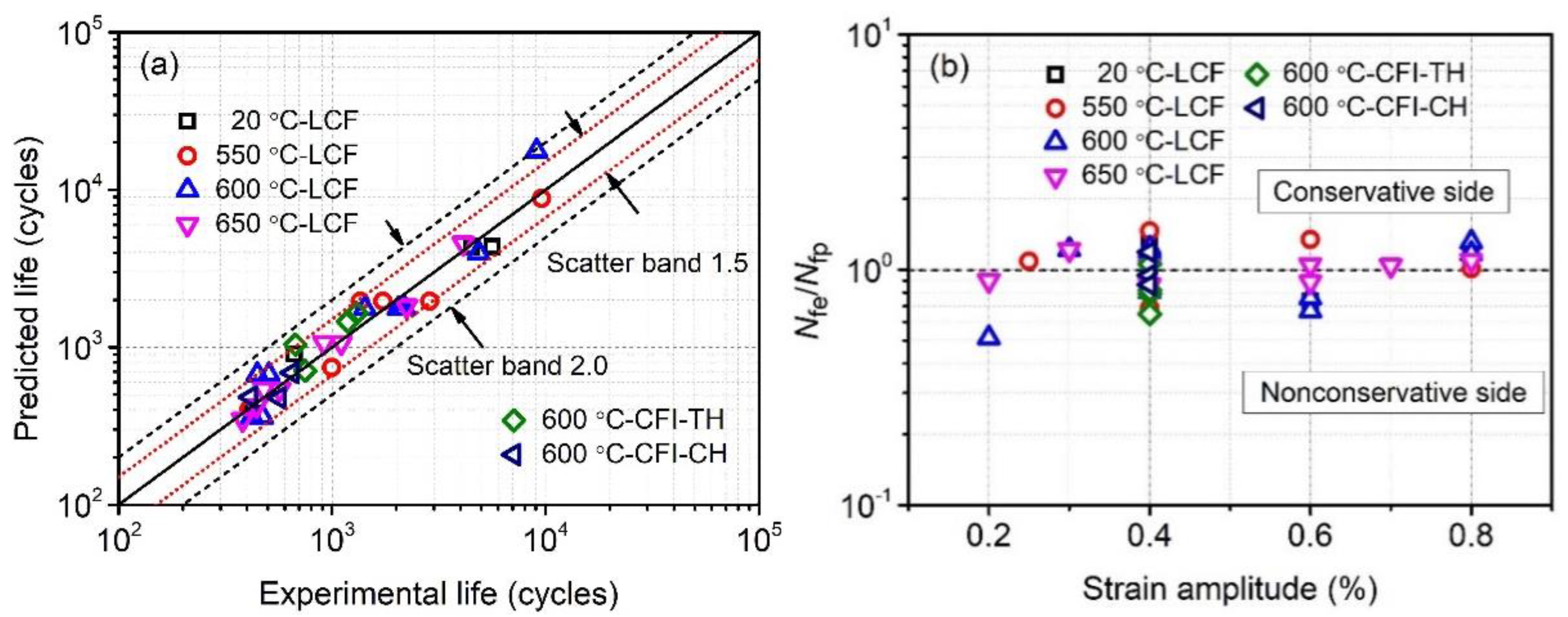
6.3. Model Validation

Since the proposed modified MCB prediction model is purely empirical, its reliability should be validated through comprehensive experimental results, especially experimental data that is beyond the range of experiments from which the fitting constants are evaluated. In Figure 10, LCF and CFI-TCH data of P91 steel at 550 °C has been validated. Furthermore, more comprehensive experimental results at various loading conditions are used to perform the validation, as listed in Table 7. It should be noted that in the experimental validation data, different 9–12% Cr steels are covered, including reduced-activation ferritic martensitic (RAFM) steel, which is designed for fusion applications [41]. Moreover, CFI-TCH experimental data are also included. Figure 11a and b present a comparison between the predicted fatigue life by using modified MCB model and the reported experimental results under LCF and CFI loadings, respectively. It is observed that the predicted results are in good agreement with the experimental results, which shows that the proposed modified MCB model can properly take into account the effects of temperature, hold time and hold direction in different 9–12% Cr ferritic-martensitic steels. However, the model does not take into account the strain rate effect due to its ambiguous effect on fatigue life when the strain rate ranges from 0.001 s−1 to 0.003 s−1, as listed in Table 7. Further investigation on the strain rate is required in the future. However, it should be emphasized that the proposed model is only applicable to ferritic-martensitic steels, which show shorter life spans under compressive dwell conditions than those of equal tensile dwell conditions in air conditions.

7. Summary and Conclusions

Various LCF and CFI tests of P92 steel were carried out at different temperatures. The effects of temperature, strain amplitude, hold time, hold direction on fatigue life are investigated. In accordance with the test results, temperature is found to play an important role in the LCF life determination when strain amplitude is low. In contrast, as the strain amplitude exceeds 0.6%, LCF life tends to be saturated, regardless of strain amplitude and temperature. As for CFI tests, a dramatic reduction in fatigue life is observed when the specimen yields short periods of tensile hold or compressive hold. Similarly, the reduction also exhibits saturated behavior at prolonged hold periods, while compressive hold introduces higher degradation on fatigue life than that of the tensile hold time. Moreover, compared to tensile hold conditions, a shorter hold time is required to achieve saturated degradation behavior for the CFI-CH tests.
To predict the LCF and CFI life spans, various fatigue life prediction models are reviewed and evaluated. The predicted life spans given by the EB and FS models can only be obtained on the basis of experimentally-determined stabilized plastic strain energy density and plastic strain, respectively. This is not the intention of a life prediction model. In contrast, the MCB prediction model only relies on known strain amplitude in the LCF test. Unfortunately, the MCB model doesn’t consider the effects of temperature and hold conditions. Consequently, a modified MCB model is proposed which takes into account interactive effects between strain amplitudes, temperatures, hold time and hold direction. The advantage of the new model is that only the known experimental input parameters are required to perform the prediction. Significantly, its predictive capacity has been validated by the conducted tests of P92 steel and by the comprehensive literature experimental data of various 9–12% Cr ferritic-martensitic steels. However, it should be emphasized that the proposed model is only applicable to ferritic-martensitic steels tested in air conditions.

Author Contributions

X.W. performed the calculations and wrote the manuscript; J.G. and M.A.W. supervised the findings of this work. W.Z. and T.Z. assisted in the experiments and prepared the test specimens. All authors discussed the results and contributed to the final manuscript.

Funding

The authors gratefully acknowledge the financial support of the National Key R&D Program of China (No. 2018YFC0808800), the China Postdoctoral Science Foundation (No. 2016M600405), Innovation Program for Graduate Students in Jiangsu Province of China (No. KYCX17_0935) and the DeMoPreCI-MDT SIM SBO project funded by Flemish government. The authors also would like to acknowledge the financial support of the Research Foundation-Flanders (FWO), The Luxembourg National Research Fund (FNR) and Slovenian Research Agency (ARRS) in the framework of the FWO Lead Agency project: G018916N ‘Multi-analysis of fretting fatigue using physical and virtual experiments’.

Conflicts of Interest

The authors declare no conflict of interest.

References

  1. Wang, R.-Z.; Zhang, X.-C.; Gong, J.-G.; Zhu, X.-M.; Tu, S.-T.; Zhang, C.-C. Creep-fatigue life prediction and interaction diagram in nickel-based GH4169 superalloy at 650 °C based on cycle-by-cycle concept. Int. J. Fatigue 2017, 97, 114–123. [Google Scholar] [CrossRef]
  2. Zhang, H.; Xie, D.; Yu, Y.; Yu, L. Online optimal control schemes of inlet steam temperature during startup of steam turbines considering low cycle fatigue. Energy 2016, 117, 105–115. [Google Scholar] [CrossRef]
  3. Jing, H.; Luo, Z.; Xu, L.; Zhao, L.; Han, Y. Low cycle fatigue behavior and microstructure evolution of a novel 9Cr–3W–3Co tempered martensitic steel at 650 °C. Mater. Sci. Eng. A 2018, 731, 394–402. [Google Scholar] [CrossRef]
  4. Berriche, R.; Fine, M.E.; Jeannotte, D.A. Environmental and hold time effects on fatigue of low-tin lead-based solder. Metall. Trans. A 1991, 22, 357–366. [Google Scholar] [CrossRef]
  5. Luo, Y.; Jiang, W.; Zhang, Y.-C.; Zhou, F.; Tu, S.-T. A new damage evolution model to estimate the creep fracture behavior of brazed joint under multiaxial stress. Int. J. Mech. Sci. 2018, 149, 178–189. [Google Scholar] [CrossRef]
  6. Marmy, P.; Kruml, T. Low cycle fatigue of Eurofer 97. J. Nucl. Mater. 2008, 377, 52–58. [Google Scholar] [CrossRef]
  7. Lee, S.Y.; Lu, Y.L.; Liaw, P.K.; Chen, L.J.; Thompson, S.A.; Blust, J.W.; Browning, P.F.; Bhattacharya, A.K.; Aurrecoechea, J.M.; Klarstrom, D.L. Hold-time effects on elevated-temperature low-cycle-fatigue and crack-propagation behaviors of HAYNES® 188 superalloy. J. Mater. Sci. 2009, 44, 2945–2956. [Google Scholar] [CrossRef]
  8. Srinivasan, V.S.; Nagesha, A.; Valsan, M.; Rao, K.B.S.; Mannan, S.L.; Sastry, D.H. Effect of hold-time on low cycle fatigue behaviour of nitrogen bearing 316L stainless steel. Int. J. Press. Vessel. Pip. 1999, 76, 863–870. [Google Scholar] [CrossRef]
  9. Gopinath, K.; Gupta, R.K.; Sahu, J.K.; Ray, P.K.; Ghosh, R.N. Designing P92 grade martensitic steel header pipes against creep–fatigue interaction loading condition: Damage micromechanisms. Mater. Des. 2015, 86, 411–420. [Google Scholar] [CrossRef]
  10. Wang, X.; Zhang, W.; Gong, J.; Wahab, M.A. Low cycle fatigue and creep fatigue interaction behavior of 9Cr-0.5Mo-1.8W-V-Nb heat-resistant steel at high temperature. J. Nucl. Mater. 2018, 505, 73–84. [Google Scholar] [CrossRef]
  11. Chauhan, A.; Hoffmann, J.; Litvinov, D.; Aktaa, J. High-temperature low-cycle fatigue behavior of a 9Cr-ODS steel: Part 1-pure fatigue, microstructure evolution and damage characteristics. Mater. Sci. Eng. A 2017, 707, 207–220. [Google Scholar] [CrossRef]
  12. Verma, P.; Basu, J.; Santhi Srinivas, N.C.; Singh, V. Deformation behavior of modified 9Cr–1Mo steel under low cycle fatigue at 600 °C. Mater. Charact. 2017, 131, 244–252. [Google Scholar] [CrossRef]
  13. Klueh, R.; Nelson, A. Ferritic/martensitic steels for next-generation reactors. J. Nucl. Mater. 2007, 371, 37–52. [Google Scholar] [CrossRef]
  14. Rees, D.W.A. Life prediction techniques for combined creep and fatigue. Prog. Nucl. Energy 1987, 19, 211–239. [Google Scholar] [CrossRef]
  15. Cui, W. A state-of-the-art review on fatigue life prediction methods for metal structures. J. Mar. Sci. Technol. 2002, 7, 43–56. [Google Scholar] [CrossRef]
  16. Pineau, A.; Antolovich, S.D. High temperature fatigue of nickel-base superalloys–A review with special emphasis on deformation modes and oxidation. Eng. Fail. Anal. 2009, 16, 2668–2697. [Google Scholar] [CrossRef]
  17. Yan, X.-L.; Zhang, X.-C.; Tu, S.-T.; Mannan, S.-L.; Xuan, F.-Z.; Lin, Y.-C. Review of creep–fatigue endurance and life prediction of 316 stainless steels. Int. J. Press. Vessel. Pip. 2015, 126–127, 17–28. [Google Scholar] [CrossRef]
  18. Santecchia, E.; Hamouda, A.M.S.; Musharavati, F.; Zalnezhad, E.; Cabibbo, M.; El Mehtedi, M.; Spigarelli, S. A Review on Fatigue Life Prediction Methods for Metals. Adv. Mater. Sci. Eng. 2016, 2016, 1–26. [Google Scholar] [CrossRef]
  19. Kamal, M.; Rahman, M.M. Advances in fatigue life modeling: A review. Renew. Sustain. Energy Rev. 2018, 82, 940–949. [Google Scholar] [CrossRef]
  20. Fournier, B.; Sauzay, M.; Caes, C.; Noblecourt, M.; Mottot, M.; Bougault, A.; Rabeau, V.; Pineau, A. Creep–fatigue–oxidation interactions in a 9Cr–1Mo martensitic steel. Part I: Effect of tensile holding period on fatigue lifetime. Int. J. Fatigue 2008, 30, 649–662. [Google Scholar] [CrossRef]
  21. Wang, R.-Z.; Zhang, X.-C.; Tu, S.-T.; Zhu, S.-P.; Zhang, C.-C. A modified strain energy density exhaustion model for creep–fatigue life prediction. Int. J. Fatigue 2016, 90, 12–22. [Google Scholar] [CrossRef]
  22. Yu, Z.-Y.; Zhu, S.-P.; Liu, Q.; Liu, Y. Multiaxial fatigue damage parameter and life prediction without any additional material constants. Materials 2017, 10, 923. [Google Scholar] [CrossRef] [PubMed]
  23. Kaae, J. High-temperature low-cycle fatigue of Alloy 800H. Int. J. Fatigue 2009, 31, 332–340. [Google Scholar] [CrossRef]
  24. Zerbst, U.; Ainsworth, R.A.; Beier, H.T.; Pisarski, H.; Zhang, Z.L.; Nikbin, K.; Nitschke-Pagel, T.; Münstermann, S.; Kucharczyk, P.; Klingbeil, D. Review on fracture and crack propagation in weldments–A fracture mechanics perspective. Eng. Fract. Mech. 2014, 132, 200–276. [Google Scholar] [CrossRef]
  25. Ainsworth, R.A.; Ruggles, M.B.; Takahashi, Y. Flaw Assessment Procedure for High-Temperature Reactor Components. J. Press. Vessel Technol. 1992, 114, 166–170. [Google Scholar] [CrossRef]
  26. Wen, J.-F.; Liu, Y.; Srivastava, A.; Benzerga, A.A.; Tu, S.-T.; Needleman, A. Environmentally enhanced creep crack growth by grain boundary cavitation under cyclic loading. Acta Mater. 2018, 153, 136–146. [Google Scholar] [CrossRef]
  27. Fournier, B.; Sauzay, M.; Caes, C.; Noblecourt, M.; Mottot, M.; Bougault, A.; Rabeau, V.; Man, J.; Gillia, O.; Lemoine, P. Creep–fatigue–oxidation interactions in a 9Cr–1Mo martensitic steel. Part III: Lifetime prediction. Int. J. Fatigue 2008, 30, 1797–1812. [Google Scholar] [CrossRef]
  28. Zhao, L.; Nikbin, K.M. Characterizing high temperature crack growth behaviour under mixed environmental, creep and fatigue conditions. Mater. Sci. Eng. A 2018, 728, 102–114. [Google Scholar] [CrossRef]
  29. Wei, Z.; Yang, F.; Lin, B.; Luo, L.; Konson, D.; Nikbin, K. Deterministic and probabilistic creep–fatigue–oxidation crack growth modeling. Probabilistic Eng. Mech. 2013, 33, 126–134. [Google Scholar] [CrossRef]
  30. Tu, S.T.; Zhang, X.C. Fatigue Crack Initiation Mechanisms. Ref. Modul. Mater. Sci. Mater. Eng. 2016, 1–23. [Google Scholar]
  31. Chaboche, J.-L. Continuous damage mechanics—A tool to describe phenomena before crack initiation. Nucl. Eng. Des. 1981, 64, 233–247. [Google Scholar] [CrossRef]
  32. Zhu, S.-P.; Huang, H.-Z.; He, L.-P.; Liu, Y.; Wang, Z. A generalized energy-based fatigue–creep damage parameter for life prediction of turbine disk alloys. Eng. Fract. Mech. 2012, 90, 89–100. [Google Scholar] [CrossRef]
  33. Chaboche, J.L. A review of some plasticity and viscoplasticity constitutive theories. Int. J. Plast. 2008, 24, 1642–1693. [Google Scholar] [CrossRef]
  34. Fatemi, A.; Yang, L. Cumulative fatigue damage and life prediction theories: A survey of the state of the art for homogeneous materials. Int. J. Fatigue 1998, 20, 9–34. [Google Scholar] [CrossRef]
  35. Fournier, B.; Sauzay, M.; Caës, C.; Noblecourt, M.; Mottot, M. Analysis of the hysteresis loops of a martensitic steel: Part I: Study of the influence of strain amplitude and temperature under pure fatigue loadings using an enhanced stress partitioning method. Mater. Sci. Eng. A 2006, 437, 183–196. [Google Scholar] [CrossRef]
  36. Coffin, L.F. A study of the effect of cyclic thermal stresses on a ductile metal. Trans ASME 1954, 76, 931–950. [Google Scholar]
  37. Manson, S.S. Fatigue: A complex subject–some simple approximation. Exp. Mech. 1965, 5, 193–226. [Google Scholar] [CrossRef]
  38. Fournier, B.; Dalle, F.; Sauzay, M.; Longour, J.; Salvi, M.; Caës, C.; Tournié, I.; Giroux, P.F.; Kim, S.H. Comparison of various 9–12%Cr steels under fatigue and creep-fatigue loadings at high temperature. Mater. Sci. Eng. A 2011, 528, 6934–6945. [Google Scholar] [CrossRef]
  39. Nagesha, A.; Valsan, M.; Kannan, R.; Bhanu Sankara Rao, K.; Mannan, S.L. Influence of temperature on the low cycle fatigue behaviour of a modified 9Cr–1Mo ferritic steel. Int. J. Fatigue 2002, 24, 1285–1293. [Google Scholar] [CrossRef]
  40. Basquin, O.H. The exponential law of endurance tests. Proc. Am. Soc. Test. Mater. 1910, 10, 625–630. [Google Scholar]
  41. Shankar, V.; Mariappan, K.; Sandhya, R.; Laha, K.; Bhaduri, A.K. Long term creep-fatigue interaction studies on India-specific reduced activation ferritic-martensitic (IN-RAFM) steel. Int. J. Fatigue 2017, 98, 259–268. [Google Scholar] [CrossRef]
  42. Ellyin, F.; Kujawski, D. Plastic Strain Energy in Fatigue Failure. J. Press. Vessel Technol. 1984, 106, 342–347. [Google Scholar] [CrossRef]
  43. Kanchanomai, C.; Mutoh, Y. Low-cycle fatigue prediction model for Pb-free solder 96.5Sn-3.5Ag. J. Electron. Mater. 2004, 33, 329–333. [Google Scholar] [CrossRef]
  44. Morrow, J.D. Cyclic plastic strain energy and the fatigue of metals. In Internal Friction, Damping, and Cyclic Plasticity; ASTM STP 378 American Society for Testing and Materials: Philadelphia, PA, USA, 1965; pp. 45–84. [Google Scholar]
  45. Coffin, L.F. Concept of Frequency Separation in Life Prediction for Time-Dependent Fatigue; General Electric Co.: Schenectady, NY, USA, 1976. [Google Scholar]
  46. Samantaray, D.; Mandal, S.; Bhaduri, A.K. A comparative study on Johnson Cook, modified Zerilli–Armstrong and Arrhenius-type constitutive models to predict elevated temperature flow behaviour in modified 9 Cr–1 Mo steel. Comput. Mater. Sci. 2009, 47, 568–576. [Google Scholar] [CrossRef]
  47. Führer, U.; Aktaa, J. Modeling the cyclic softening and lifetime of ferritic-martensitic steels under creep-fatigue loading. Int. J. Mech. Sci. 2018, 136, 460–474. [Google Scholar] [CrossRef]
  48. Guguloth, K.; Sivaprasad, S.; Chakrabarti, D.; Tarafder, S. Low-cyclic fatigue behavior of modified 9Cr–1Mo steel at elevated temperature. Mater. Sci. Eng. A 2014, 604, 196–206. [Google Scholar] [CrossRef]
  49. Zhang, S.-L.; Xuan, F.-Z. Interaction of cyclic softening and stress relaxation of 9–12% Cr steel under strain-controlled fatigue-creep condition: Experimental and modeling. Int. J. Plast. 2017, 98, 45–64. [Google Scholar] [CrossRef]
  50. Saad, A.A. Cyclic Plasticity and Creep of Power Plant Materials; University of Nottingham: Nottingham, UK, 2012. [Google Scholar]
Figure 1. Schematic waveforms used for LCF and CFI tests with tensile hold (CFI-TH) or compressive hold (CFI-CH).
Metals 09 00183 g001
Figure 2. Relationships between the fatigue life and total strain amplitude at different temperatures.
Metals 09 00183 g002
Figure 3. Strain amplitude versus cycle number of fatigue life at different temperatures: (a) 20 °C, (b) 550 °C, (c) 600 °C, (d) 650 °C.
Metals 09 00183 g003
Figure 4. Effects of hold time and hold direction on the fatigue life.
Metals 09 00183 g004
Figure 5. Relationship between strain amplitude and cycle number of fatigue life at LCF and CFI loadings.
Metals 09 00183 g005
Figure 6. (a) Comparison between experimental life and predicted life using MCB model, (b) the ratio of experimental life to predicted life versus different strain amplitudes.
Metals 09 00183 g006
Figure 7. (a) Comparison between experimental life and predicted life using EB model, (b) the ratio of experimental life to predicted life versus different strain amplitudes.
Metals 09 00183 g007
Figure 8. (a) Comparison between experimental life and predicted life using FS model, (b) the ratio of experimental life to predicted life versus different strain amplitudes.
Metals 09 00183 g008
Figure 9. (a) Comparison between experimental life and predicted life using MMCB model, (b) the ratio of experimental life to predicted life versus different strain amplitudes.
Metals 09 00183 g009
Figure 10. Comparison between experimental life from [47] and predicted life using MMCB model.
Metals 09 00183 g010
Figure 11. Comparison between experimental life from [9,38,41,48,49,50] and predicted life using MMCB model at (a) LCF and (b) CFI loadings.
Metals 09 00183 g011
Table 1. LCF and CFI test data for P92 steel.
Test Serial No.Temperature (°C)Strain AmplitudeTH Time, tt (min)CH Time, tc (min)Cycle Number of Life
PF20S04200.4%//5640/4513
PF20S06200.6%//667
PF20S08200.8%//423
PF550S0255500.25%//9599
PF550S045500.4%//2874/1734/1356
PF550S065500.6%//997
PF550S085500.8%//410
PF600S026000.2%//9078
PF600S036000.3%//4861
PF600S046000.4%//2045/2120/2186/1426
CF600S04T016000.4%1/1303
CF600S04T036000.4%3/1190
CF600S04T106000.4%10/675
CF600S04T606000.4%60/748
CF600S04C016000.4%/1652
CF600S04C036000.4%/3416
CF600S04C106000.4%/10567
PF600S066000.6%//447/506
PF600S086000.8%//473/422
PF650S026500.2%//4124
PF650S036500.3%//2232
PF650S046500.4%//1102/918
PF600S066500.6%//480/568
PF600S076500.7%//444
PF600S086500.8%//381
Table 2. Coffin-Manson-Basquin model parameters of P92 steel at different temperatures.
TemperatureE (MPa)σ’fbεfc
20 °C198,476723−0.0380.174−0.53
550 °C151,195490−0.0650.463−0.65
600 °C134,509397−0.0680.341−0.61
650 °C132,150319−0.0801.170−0.79
Table 3. CFI test data for P91 steel from [47].
Test No.Temperature (°C)Strain Rate (s−1)Strain AmplitudeTH Time, tt (min)CH Time, tc (min)Cycle Number of Life
15500.0010.3%1/6650
25500.0010.3%/12233
35500.0010.3%/101831
45500.0010.5%1/1010
55500.0010.5%/1821
65500.0010.5%/10599
75500.0010.5%/60602
85500.0010.75%1/550
95500.0010.75%10/485
105500.0010.75%60/573
115500.0010.75%/1521
125500.0010.75%/10406
135500.0010.75%/60426
145500.0010.75%1010340
Table 4. Modified MCB model parameters identified from LCF lives at different temperatures.
Parametersτi (i = 1,2,3,4)φi (i = 1,2,3,4)ωi (i = 1,2,3,4)γi (i = 1,2,3,4)
σ f ( T * ) 29,970−27,6385345723
b ( T * ) −9.827.18−1.39−0.038
ε f ( T * ) 1075.33−802.14149.890.174
c ( T * ) −251.94189.22−35.72−0.53
Table 5. Modified MCB model parameters identified from CFI lives at various hold conditions.
Tensile Hold ConditionCompressive Hold Condition
αtβtgthtαcβcgchc
0.60.689.211850.730.1219.31893
Table 6. Parameters required for the fatigue life prediction in various models.
ModelMCBEBFSModified MCB
AbilityLCFLCF, CFILCF, CFILCF, CFI
Required ParametersεaWpεapυtυcεatttcT
Status××
√: Known parameter; ×: Experimentally determined parameter.
Table 7. References reporting experimental life for LCF and CFI loadings on 9–12% Cr steels.
MaterialTemperature (°C)Strain rate (s−1)Type of TestTH Time, tt (min)CH Time, tc (min)Ref.
Modified 9Cr-1Mo500, 6000.001LCF//[48]
P926250.002LCF, CFI0.5, 2, 5/[49]
P916000.001LCF//[50]
RAFM5500.003LCF, CFI10/[41]
P926000.001LCF, CFI1, 5, 101, 5, 10[9]
P925500.002LCF//[38]

