Abstract
A2024 alloy foams were fabricated by two methods. In the first method, the melt was thickened by Mg, which acts as an alloying element (melt route). In the second method, the melt was thickened by using primary crystals at a semi-solid temperature with a solid fraction of 20% (semi-solid route). A2024 alloy foams fabricated through the semi-solid route had coarse and uneven pores. This led to slightly brittle fracture of the foams, which resulted in larger energy absorption efficiency than that of the foams fabricated through the melt route. Moreover, A2024 alloy foams fabricated through the semi-solid route had a coarser grain size because of the coarse primary crystals. However, by preventing the decrease in the alloying element Mg, the θ/θ’ phase was suppressed. Additionally, by preventing the precipitation of the S′ phase, the amount of Guinier-Preston-Bagaryatsky (GPB) zone increased. This resulted in a larger plateau stress.
1. Introduction
Improvements in fuel consumption and safety are now required in transportation equipment, including automobiles and aircraft. To improve the fuel economy, it is necessary to reduce weight. However, shock absorption performance should be maintained in case of accidents. Aluminum foam has attracted attention as a material that satisfies such characteristics. Aluminum foams contain a large quantity of pores inside the material, which is thus ultralight and has excellent shock absorbing properties. Therefore, aluminum foam is expected to be applied in transportation as an ultralight shock absorbing material.
To manufacture aluminum foam, the method known as melt route or the Alporas method [1] can enlarge the foam at a relatively low cost. In this method, first, Ca as a thickener is added to the melt, and CaO is generated by reaction with the atmosphere [2]. Subsequently, CaO is spread into the melt, and the viscosity of the melt is increased. TiH2 is then added to the melt as a blowing agent. Finally, the foam is obtained by water cooling. However, to apply aluminum foams as an ultralight shock absorbing material of transport equipment, an improvement in the compressive properties of foams is needed. The compressive properties of foams are known to be determined by the strength of the base metal and pore morphology [3]. Therefore, using super duralumin A2024 alloy (Al-Cu-Mg) which is known as high strength lightweight material for base metal to increase strength and controlling the pore morphology to improve compressive properties has been researched. Fukui et al. generated an oxide of Mg [4,5], which is contained in the A2024 alloy as a thickener instead of adding Ca. However, the decrease in the base metal strength has been an issue of concern, because of the decrease in Mg, which acts as an alloying element. The decrease in Mg is known to decrease the plateau stress of the aluminum foam [6]. To solve this problem, foams were fabricated in a semi-solid state. In this study, this method is called the semi-solid route. In this method, primary crystals are used as a thickener [7] instead of an oxide. In our group, we found it is possible to fabricate the A2024 alloy foam without adding any thickener and confirmed the thickening effect of the primary crystal in a semi-solid state [8]. However, the size of the primary crystal is larger than that of the oxide. Therefore, the primary crystal existing inside the melt may affect the pore morphology of the aluminum alloy foam in a semi-solid state. Hence, the objective of this research is to investigate the effect of the cell wall structure and pore morphology on the compressive properties of A2024 alloy foam fabricated through the melt route and the semi-solid route.
We fabricated an A2024 alloy foam through melt and semi-solid routes and researched the effect of the cell wall structure and pore morphology on compressive properties (plateau stress and energy absorption efficiency). Nano-sized and micro-sized precipitates of the cell wall were analyzed. The hardness in cell walls of two kinds of foams was measured. Pore morphology of foams was evaluated by the pore diameter and pore circularity in the cross section of foams.
2. Materials and Methods
2.1. Sample Preparation
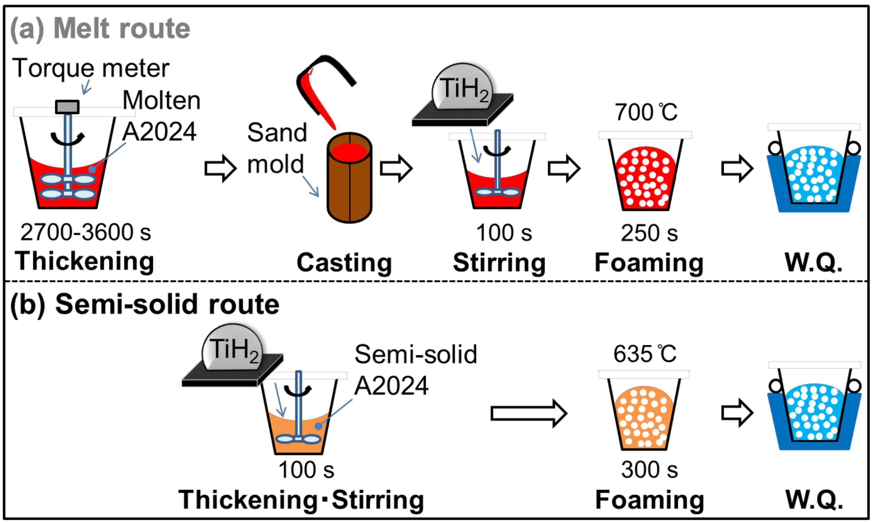
Table 1 shows the alloy composition of the A2024 alloy used in this study. Figure 1 shows the fabrication methods of the A2024 alloy foam through (a) the melt route and (b) the semi-solid route.

Table 1.
A2024 alloy composition (mass %).
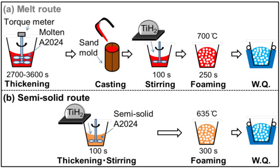
Figure 1.
Fabrication methods of A2024 foam: (a) melt route; (b) semi-solid route.
In the melt route (Figure 1a), 700 g of the A2024 alloy was set in a graphite crucible. The alloy was heated and held at 700 °C in an electric furnace. After melting, the melt was thickened by using a stirring impeller coated with BN at 500 rpm until the torque became stable (2700–3600 s). This long stirring generates MgO, which acts as a thickener in the melt by reaction with the atmosphere. The melt was then poured into a mold, and 100 g of the cast alloy was cut and placed in an SUS304 crucible coated with Al2O3. The alloy was heated to, and held at, 700 °C in an electric furnace. After the temperature became stable, 1 g of the TiH2 powder wrapped in an aluminum foil, which corresponds to 1 mass % of the alloy, was added to the melt as a blowing agent. The TiH2 powder was previously dry-treated at 150 °C for 24 h. The melt was then stirred by an impeller coated with BN at 900 rpm for 100 s. After stirring, the melt was retained for 250 s so that TiH2 decomposes. Subsequently, the crucible was taken out of the furnace. The foam was then solidified and cooled with 3 L/min of water.
In the semi-solid route (Figure 1b), 100 g of the alloy was cut and added to a crucible. The alloy was heated and held at 635 °C (solid fraction fs = 20% [9]) in an electric furnace. The following procedures to obtain the foam were the same as those of the melt route, except that the retaining time was 300 s for the semi-solid route. The retaining time was set so as to obtain the same porosity as with the melt route.
In this study, A2024 alloy foams fabricated through the melt and semi-solid routes are referred as Melt-A2024 and Semi-A2024, respectively. After the foams were obtained, the T4 treatment was applied. The foams were solid-solutionized at 480 °C for 48 h in a muffle furnace. After that, the foams were aged at room temperature for over 96 h. Finally, the hardness in the cell walls of the samples was measured by a micro-Vickers hardness tester (HM-115, Akashi Co., Ltd., Kanagawa, Japan). The test load was 2.9 N, and the size of the impression was less than 1/3 of the cell wall thickness.
2.2. Evaluation of Pore Morphology
To derive the porosity of the foam, its volume was measured via Archimedes’ method using the mass of the foam and a spring scale. In Equation (1), the porosity p of the foam was calculated on the basis of the density of the A2024 alloy foam ρP, which was calculated from the volume and mass of the foams, and the density of the A2024 alloy, ρNP = 2.77 Mg/m3 [10]. The pore size and morphology (pore diameter dp and pore circularity ep) in a cross section in the middle of the sample were measured by using image analysis software (WinROOFTM, Mitani Corp., Fukui, Japan). The pore morphology was calculated by Equations (2) and (3). The symbols S and L are the area of the pore and the perimeter of the pore, respectively. Because pores smaller than 0.2 mm in diameter cannot be distinguished from noises, these small pores were excluded from analysis.
p = (1 − ρP/ρNP) × 100%
dp = (4S/π)1/2
ep = 4πS/L2.
2.3. Measurement and Analysis of the Cell Wall
The difference in the cell wall structure between the two fabrication methods was evaluated. First, the average grain size was measured by electron back scatter diffraction (EBSD) using the TSL-OIM4 system (TSL Solutions, Kanagawa, Japan). The dimension step was 6.0 µm. The average value was calculated by Equation (4), which is the weighting average of the area for the size di of the i-th grain (di was calculated in the same way as Equation (2)). Second, electron probe micro analysis (EPMA) using the JXA-8230 electroprobe (JEOL, Kanagawa, Japan) was carried out at 15 kV. The micro-sized precipitates were analyzed by scanning electron microscope energy dispersive X-ray spectroscopy (SEM-EDS) on a JSM-6500F system (JEOL, Kanagawa, Japan) at 15 kV. The nano-sized precipitates were analyzed by transmission electron microscope energy dispersive X-ray spectroscopy (TEM-EDS), a differential scanning calorimeter (DSC), and X-ray diffraction (XRD). The elemental mapping of Mg, Mn and Cu was obtained by TEM-EDS on a JEM-2100F system (JEOL, Kanagawa, Japan) at 15 kV. Exothermic and endothermic peaks were analyzed by DSC on a DSC8500 apparatus (Perkin Elmer, Waltham, MA, USA). The weight of samples was 10 mg, the temperature zone was 0–500 °C, and the heating rate was 45 °C/min. Precipitates were analyzed by XRD on a SmartLab diffractometer (Rigaku, Tokyo, Japan).
2.4. Evaluation of Compressive Properties
The fabricated foams were cut in dimensions of 20 × 20 × 20 mm3 by wire electrical discharge machining. After that, a compression test was performed according to ISO 13314 [11] by a universal testing machine (Autograph, AG-250lNI, Shimadzu Corp., Kyoto, Japan). In the test, the strain rate de/dt was 0.1 min−1. The compressive properties, plateau stress σpl, and energy absorption efficiency ηV were calculated. The calculation method of each value is shown below. The plateau stress σpl was calculated by the average compressive stress in the range from 20 to 30% of compressive strain. The energy absorption efficiency ηV was calculated by the energy absorption amount EV and ideal energy absorption amount EVideal as in Equation (7). Further, the energy absorption amount EV and ideal energy absorption amount EVideal were calculated by Equations (5) and (6) using the maximum compressive stress σmax. Moreover, as the porosity will change after cutting to cubic, the porosity of the cubic foam sample was derived before the compression test. The volume of the cubic foam sample was calculated by measuring each side of the cube by digital calipers. The porosity of the cubic foam sample was then calculated in the same way as above by Equation (1).
EVideal = 1/100 × σmax(e = 0~50%) × e MJ/m3
ηV = (EV/EVideal) × 100%.
3. Results and Discussion
3.1. Results of the Compression Test
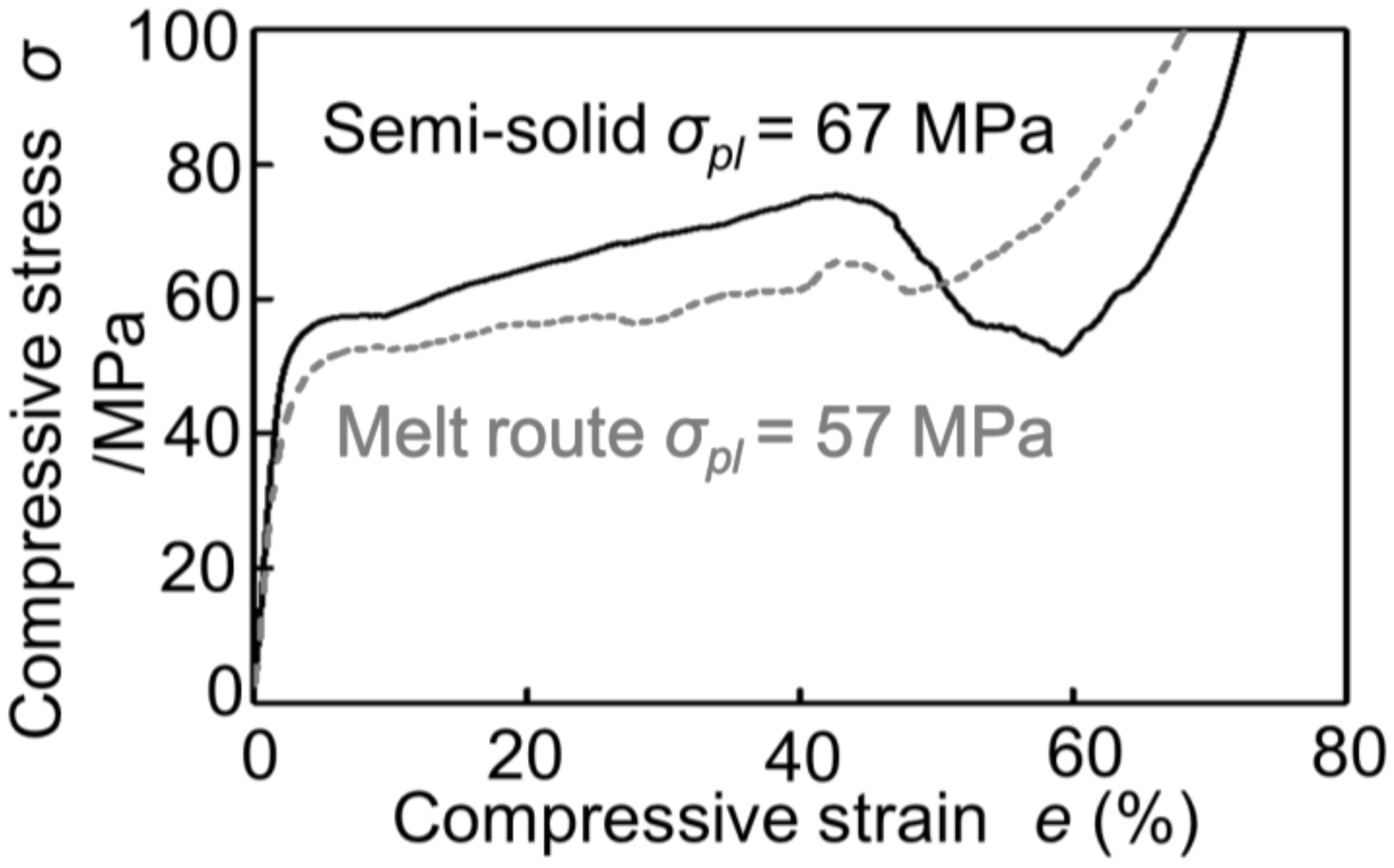
Figure 2 shows the stress–strain curves obtained by compression tests of Melt-A2024 and Semi-A2024 with almost the same porosity of the cubic foam sample (about 60%). From Figure 2, the plateau stress of Semi-A2024 was σpl = 67 MPa, which was larger than that of Melt-A2024 (σpl = 57 MPa). In addition, Semi-A2024 shows a sudden decrease in compressive stress. Figure 3 shows the energy absorption efficiency ηV. The energy absorption efficiency of Semi-A2024 was between 86 and 92%, which was larger than that of Melt-A2024 (ηV = 70–85%). The sudden decrease in compressive stress may have prevented the increase in the maximum compressive stress σmax. Therefore, Semi-A2024 may show larger energy absorption efficiency than that of Melt-A2024.

Figure 2.
Stress–strain curves (porosity about p = 60%) of Melt-A2024 and Semi-A2024.
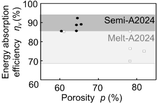
Figure 3.
Energy absorption efficiency ηV of Melt-A2024 and Semi-A2024.
3.2. Effect of Pore Morphology on Compressive Properties
3.2.1. Pore Morphology of Melt-A2024 and Semi-A2024
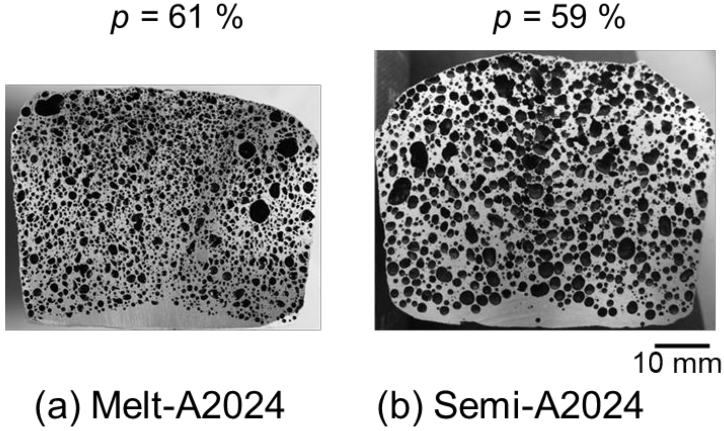
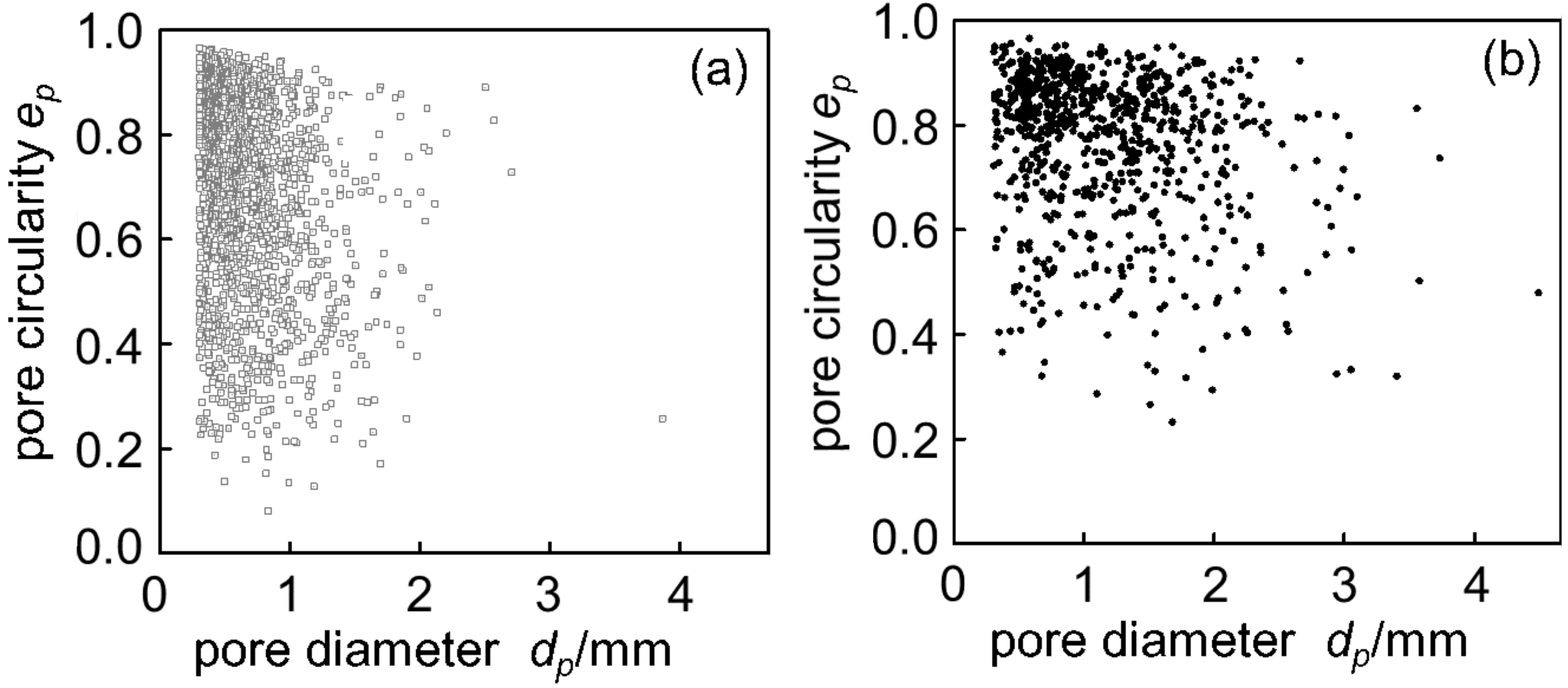
Figure 4 shows cross sections of (a) Melt-A2024 and (b) Semi-A2024 with a porosity of foams of p = 61% and p = 59%, respectively. Figure 4 shows that foams of the semi-solid route have coarse and uneven pores. Furthermore, Figure 5 shows image analysis results of the pore morphology of foams shown in Figure 4. Figure 5 shows that Semi-A2024 has coarser and more uneven pores than those of Melt-A2024. These tendencies of the Melt-A2024 and Semi-A2024 samples were observed in almost all other samples. Moreover, by increasing the retaining time, the pores will expand and become coarser, and the porosity will also increase until the end of TiH2 decomposition [5]. Moreover, it is thought that, with a change in foaming temperature, there will be no significant difference in the pores of Melt-A2024, unless the temperature falls below the liquidus line. However, for Semi-A2024, the change in temperature will generate a difference in pore formation because the fraction of solid changes [8].
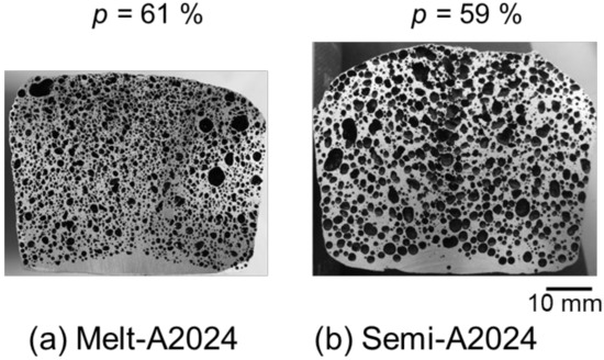
Figure 4.
Cross sections of samples: (a) Melt-A2024; (b) Semi-A2024.

Figure 5.
Distribution map of pore circularity: (a) Melt-A2024 (p = 61%); (b) Semi-A2024 (p = 59%).
3.2.2. The Compressive Behavior of A2024 Alloy Foams
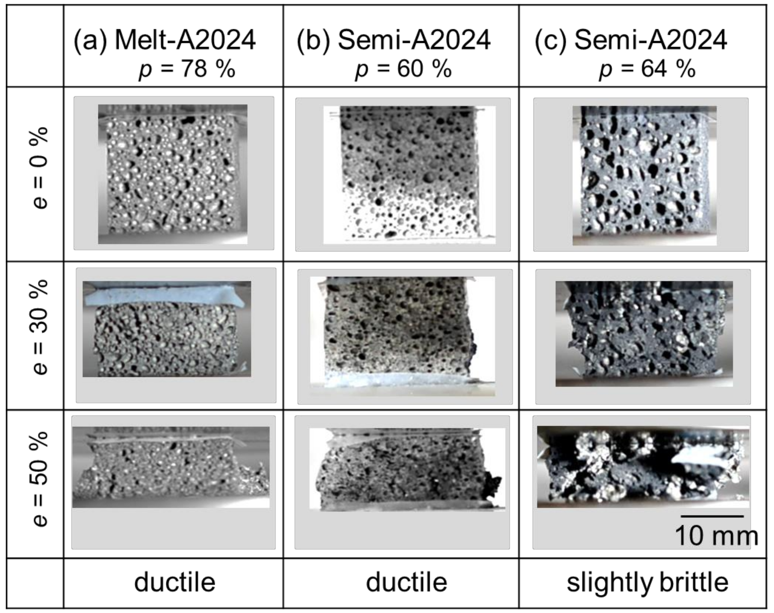
Figure 6 shows the compressive behavior of the samples during the compression test. The porosities shown in Figure 6 correspond to the cubic foam sample porosity. From Figure 6a, before the compression test (e = 0%), Melt-A2024 had finer pores. Moreover, during the compression test (e = 50%), a sudden decrease in compressive stress was not observed. Therefore, the material showed a ductile fracture. At this moment, the energy absorption efficiency of the samples was ηV = 70%. The sample shown in Figure 6b is Semi-A2024. This sample had finer pores, so it is different from that previously mentioned in Section 3.2.1. This is because Semi-A2024 showed variations in pore diameter and circularity (Figure 5b); when the sample was cut into a cube, it included much finer pores. Further, during the compression test (e = 50%), a sudden decrease in compressive stress was not observed. Therefore, the material showed a ductile fracture. At this moment, the energy absorption efficiency of the sample was ηV = 86%. Figure 6c shows the results of Semi-A2024. Before the compression test (e = 0%), the sample had coarse and uneven pores, as mentioned in Section 3.2.1. During the compression test (e = 50%), there was a sudden decrease in compressive stress after a compressive strain of approximately 40%. Therefore, the material showed a slightly brittle fracture. At this moment, the energy absorption efficiency of the sample was ηV = 89%. Thus, its energy absorption efficiency was larger than that of the other two samples. This is because the coarse and uneven pores were crushed preferentially [12], and the plateau region became flat. Therefore, Semi-A2024, which had coarse and uneven pores, showed larger energy absorption efficiency.
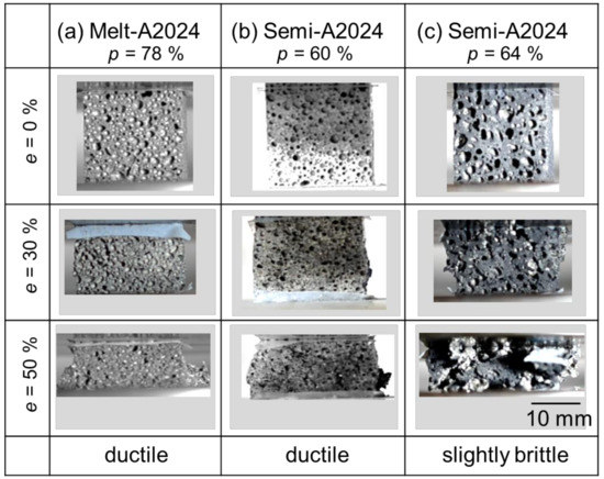
Figure 6.
Compressive behavior of the sample during compression test.
3.3. The Effect of Cell Wall Structure on Compressive Properties
3.3.1. Cell Wall Hardness
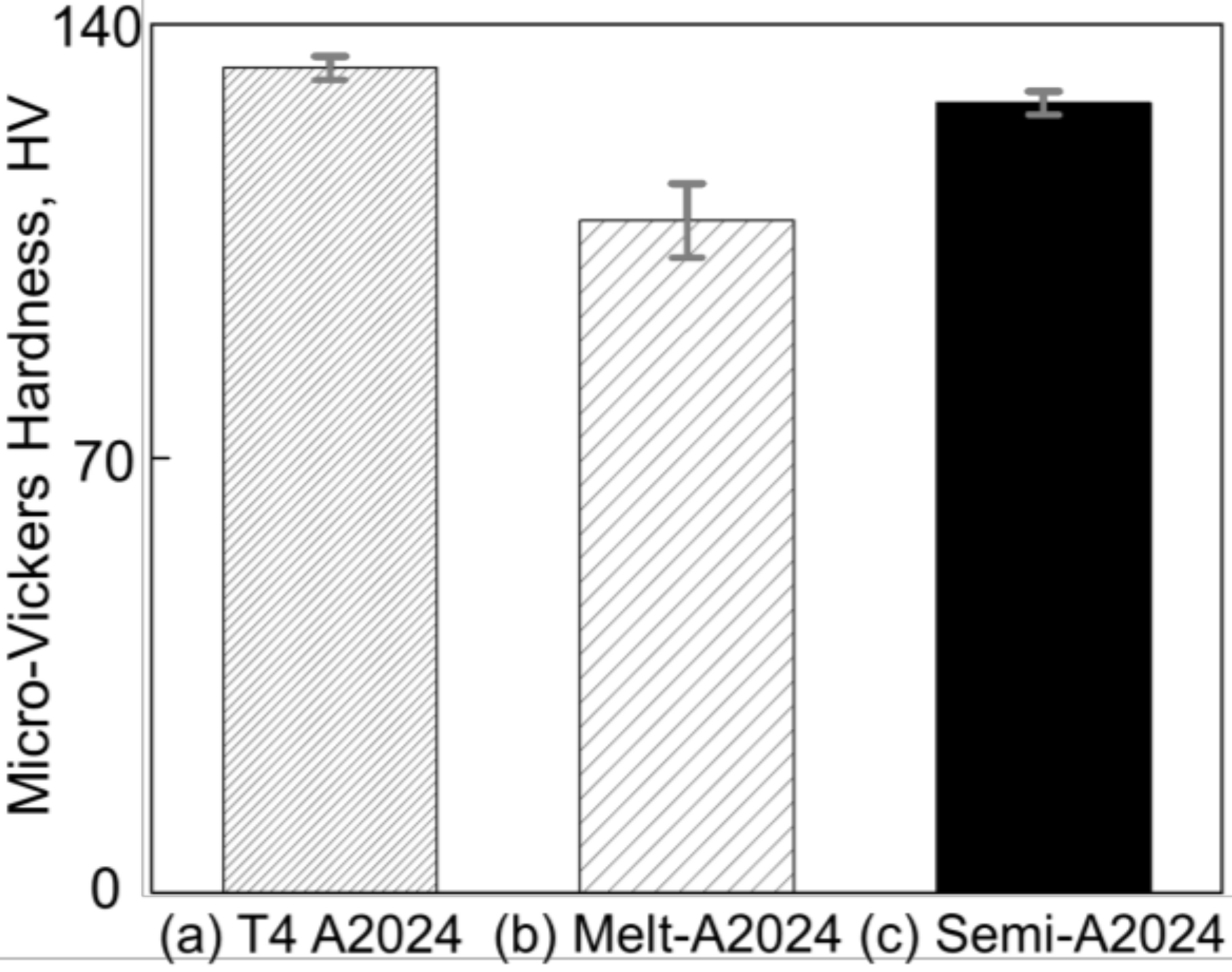
Figure 7 shows the results of micro-Vickers hardness tests of (a) T4 treated A2024, (b) cell walls of Melt-A2024, and (c) cell walls of Semi-A2024. From Figure 7, the cell wall hardness of Semi-A2024 (HV = 127) was close to that of the T4-treated A2024 (HV = 133) and larger than that of Melt-A2024 (HV = 108).

Figure 7.
Micro-Vickers hardness. (a) T4-treated A2024; (b) cell walls of Melt-A2024; (c) cell walls of Semi-A2024. The error bars show the standard deviations.
3.3.2. The Grain Size of Cell Wall
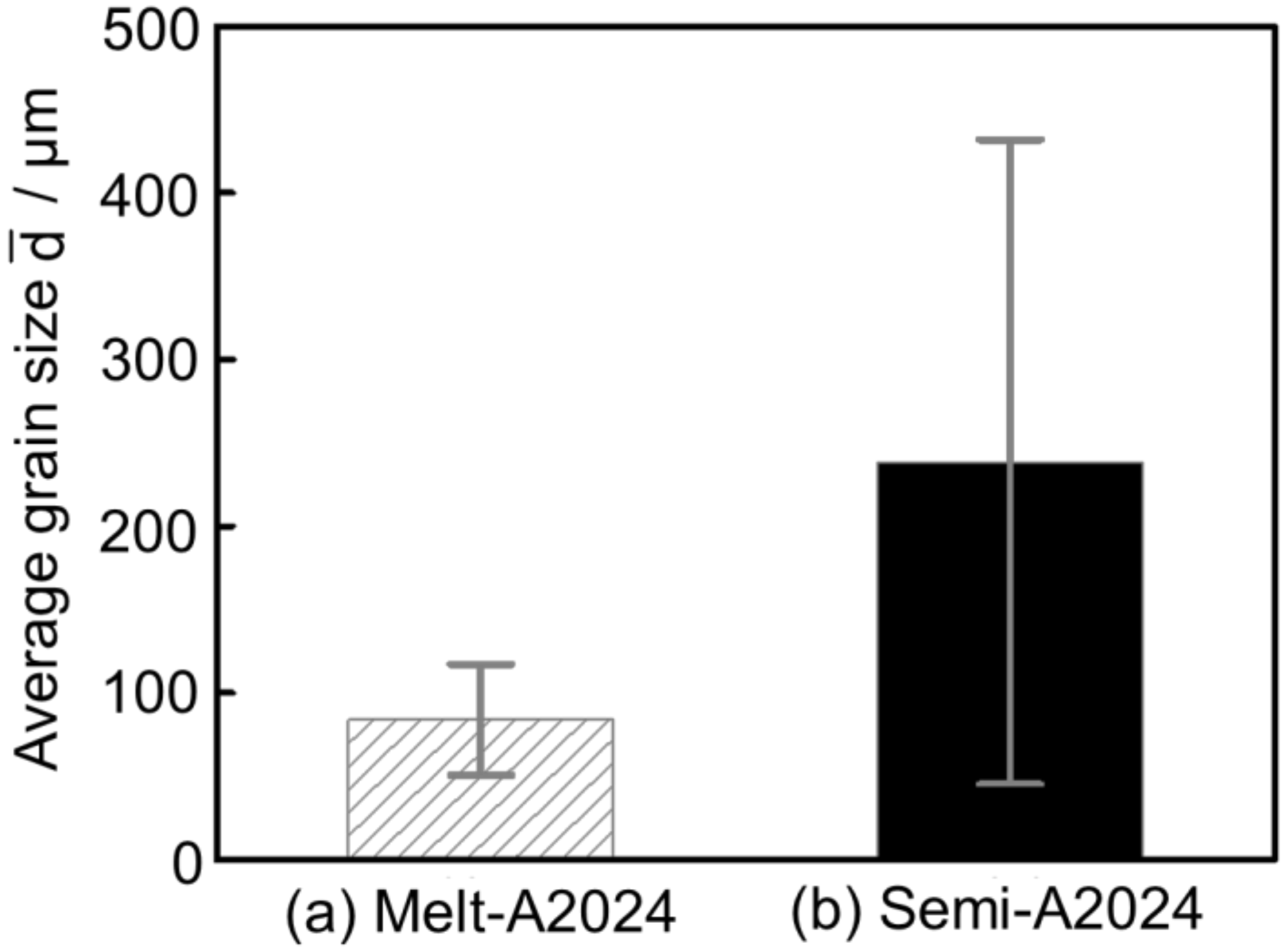
Figure 8 shows the inverse pole figure map of (a) Melt-A2024 and (b) Semi-A2024 after T4 treatment. Semi-A2024 has coarser grains because of the existence of coarse primary crystals (Figure 8b). Further, Figure 9 shows the average grain size of (a) Melt-A2024 and (b) Semi-A2024. From Figure 9, these foams had an of 84 µm and 239 µm, respectively. Therefore, the average grain size of Semi-A2024 is larger than that of Melt-A2024.
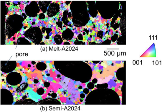
Figure 8.
Inverse pole figure map. (a) Melt-A2024; (b) Semi-A2024.

Figure 9.
Average grain size ; (a) Melt-A2024; (b) Semi-A2024. The error bars show the standard deviations.
3.3.3. MgO Amounts of Cell Wall
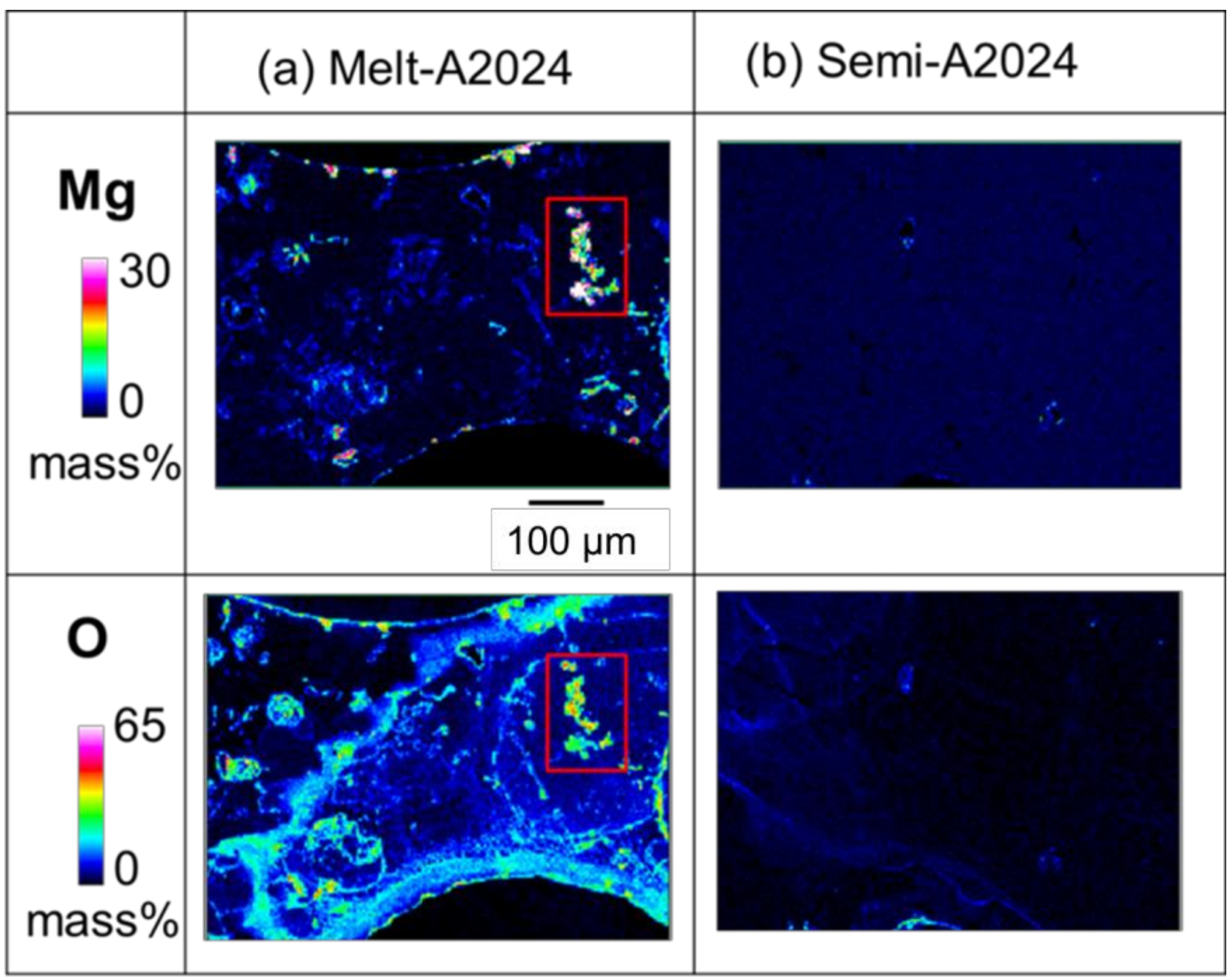
For Melt-A2024, the decrease in the base metal strength has been an issue of concern because of the decrease in Mg, which acts as an alloying element for strengthening. To estimate the amount of MgO in the cell walls of foams, an EPMA was performed. Figure 10 shows the qualitative mapping of Mg and O by EPMA. The part with high concentration of both Mg and O is considered to be MgO. As shown in the red square in Figure 10a, the concentration of MgO was high in the Melt-A2024 foams. This is due to the long period of stirring performed to thicken the melt by generating MgO. Meanwhile, parts with high concentrations of both Mg and O were rarely observed in the Semi-A2024 foams because the long stirring for thickening was excluded. Therefore, the amount of MgO in the cell walls is expected to be larger in the Melt-A2024 foams, so the hardness in the cell walls is expected to be lower.
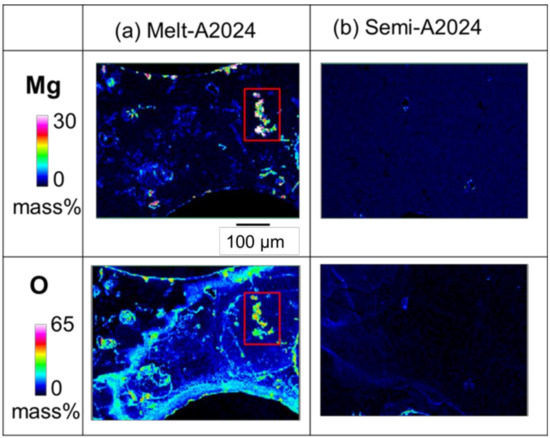
Figure 10.
X-ray elemental mapping of Mg and O in cell wall obtained by electron probe micro analysis (EPMA): (a) Melt-A2024; (b) Semi-2024.
3.3.4. Identification of Micro-Sized Precipitates
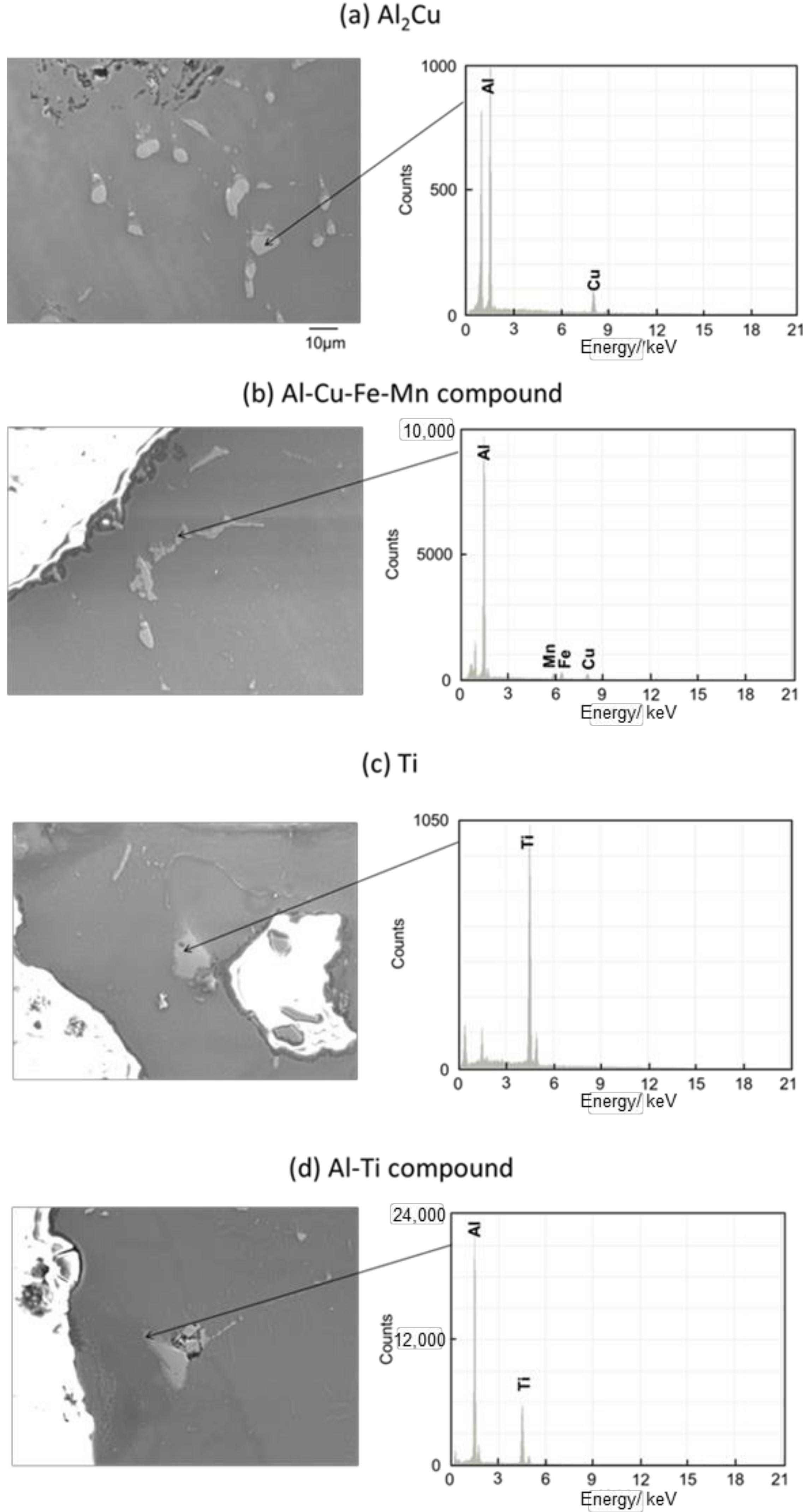
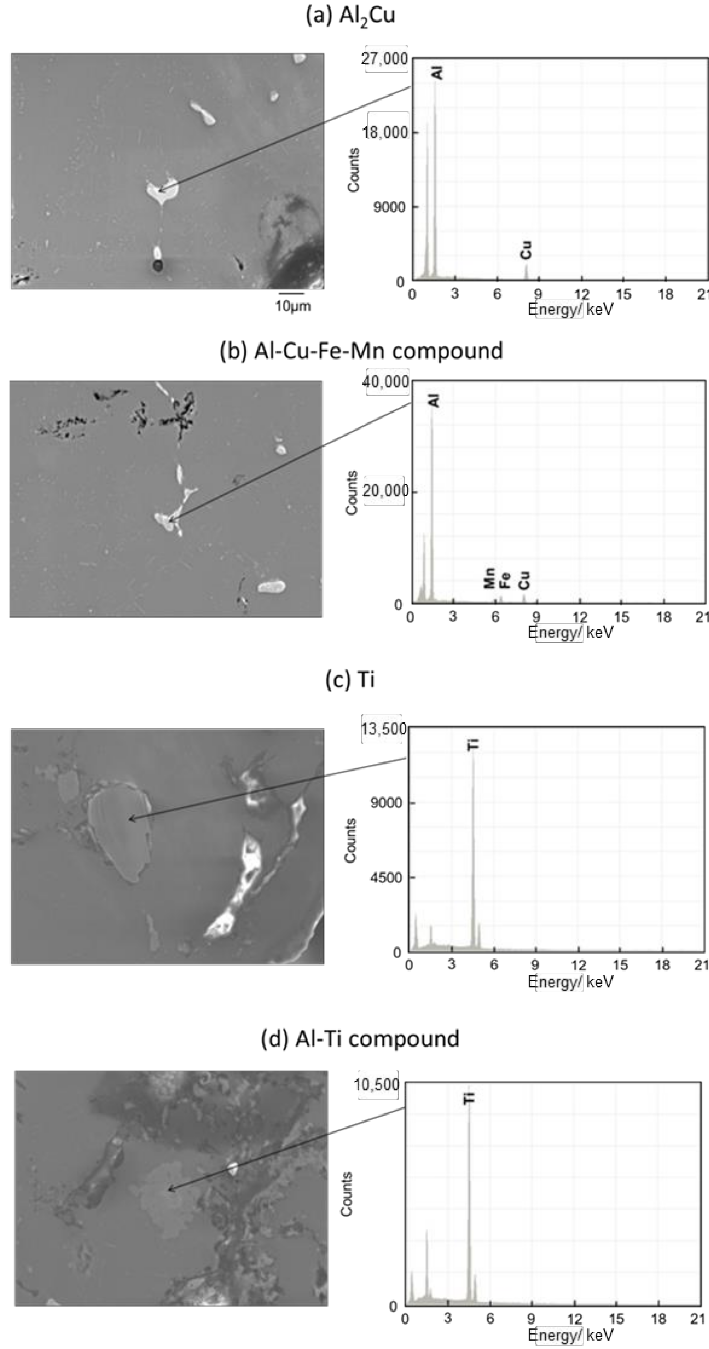
Figure 11 and Figure 12 show the images of intermetallic compounds and EDS analysis by SEM for Melt-A2024 and Semi-A2024, respectively. First, Al–Cu compounds were observed. These particles are considered to be Al2Cu (θ phase), which is a typical precipitate of A2024 [13] (Figure 11a and Figure 12a). Al–Cu–Fe–Mn compounds were also observed [13] (Figure 11b and Figure 12b). Furthermore, Ti was detected (Figure 11c and Figure 12c). This is considered to be the foaming agent, TiH2, which did not decompose and remained in the matrix. Further, an Al–Ti compound was detected (Figure 11d and Figure 12d). The titanium decomposed from TiH2 could have reacted with the aluminum matrix. No differences in the amounts of these precipitates were seen. Therefore, the effect of the difference in these micro-sized precipitates on compressive properties is considered to be small.
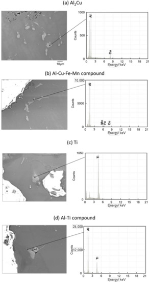
Figure 11.
Scanning electron microscope (SEM) images of intermetallic compounds and energy dispersive X-ray spectroscopy (EDS) analysis in the cell wall of Melt-A2024.
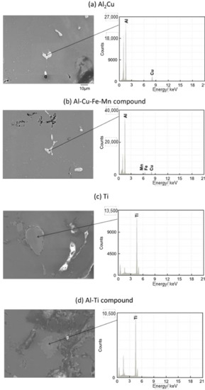
Figure 12.
SEM images of intermetallic compounds and EDS analysis of the cell wall of Semi-A2024.
3.3.5. Identification of Nano-Sized Precipitates
Differential Scanning Calorimeter
Figure 13 shows the DSC curves of (a) Melt-A2024 and (b) Semi-A2024. In Figure 13, endothermic Peak I and the exothermic Peak II are exhibited in both alloys. For the endothermic process, Peak I at approximately 240 °C could be ascribed to the dissolution of the GPB zone [14]. For the exothermic process, Peak II at approximately 280 °C could be ascribed to the precipitation of S’/S phases [15]. Therefore, the Guinier-Preston-Bagaryatsky (GPB) zone and the S’ phase, which are strengthening phases of the A2024 alloy, were observed in both alloys.
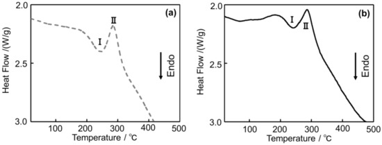
Figure 13.
Differential Scanning Calorimeter (DSC) curves of the A2024 alloy foams: (a) Melt-A2024; (b) Semi-A2024.
X-ray Diffraction
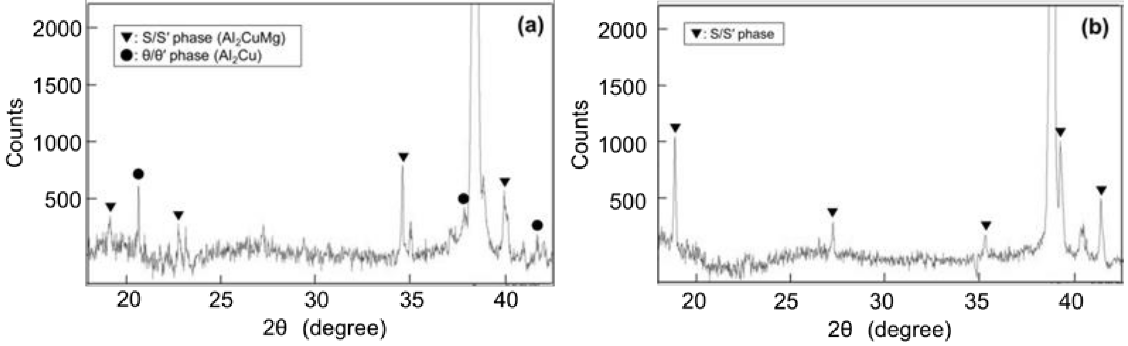
Given that the S and S’ phases and θ and θ’ phases cannot be distinguished by XRD, they are expressed as the S/S’ phase and θ/θ’ phase, respectively. Figure 14 shows the XRD patterns of (a) Melt-A2024 and (b) Semi-A2024. In Figure 14a, S/S’ and θ/θ’ phases are indicated in Melt-A2024. The precipitation of the θ phase is known to decrease the degree of age hardening [13]. Only the S/S’ phase is indicated in Semi-A2024 (Figure 14b). The θ/θ’ phase was found in Melt-A2024 and not in Semi-A2024 because the low Mg ratio in the Al–Cu alloy accelerates the precipitation of the θ/θ’ phase [16].

Figure 14.
X-ray Diffraction (XRD) patterns; (a) Melt-A2024; (b) Semi-A2024.
Transmission Electron Microscope Energy Dispersive X-ray Spectroscopy
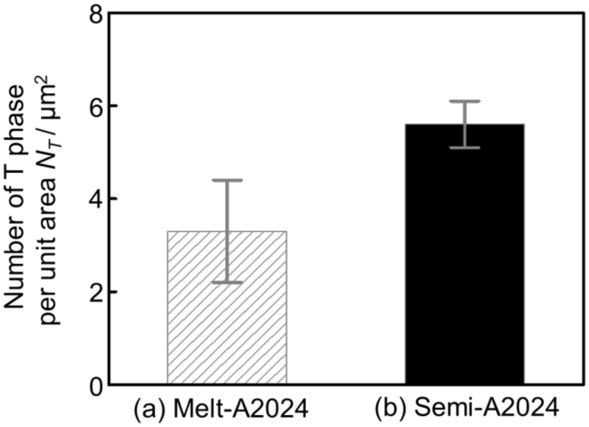
Finally, TEM-EDS was carried out to identify nano-sized precipitates. Figure 15 shows the X-ray mapping image of (a) Melt-A2024 and (b) Semi-A2024 by TEM-EDS. The upper figures show the mapping image of Mg. The middle figure shows the mapping image of Mn piled on a bright field (BF) image. The lower figures show the mapping image of Cu. According to Figure 15a, Mg was distributed completely over both Melt-A2024 and Semi-A2024. Moreover, in Melt-A2024, both Mn and Cu concentration parts were observed and are circled in red. This needle- or round-shaped precipitates are considered to be the T phase (Al20Mn2Cu3) [17]. Concentration parts of only Cu were also observed and are circled in green. These round-shaped precipitates are considered to be the θ/θ’ phase. In Semi-A2024, only Mn and Cu concentration parts were observed, which are circled in red (Figure 15b). These needle-shaped precipitates are considered to be the T phase. Figure 16 shows the number of T phases in the cell wall per unit area, NT, of (a) Melt-A2024 and (b) Semi-A2024. The numbers of T phases of these alloys were 3.3 and 5.6, respectively. Therefore, the number of T phases in the cell walls of Semi-A2024 is larger than that of Melt-A2024. From the above, in Semi-A2024, the precipitation of the θ/θ’ phase is suppressed, and this results in an increase in the precipitation of the T phase.
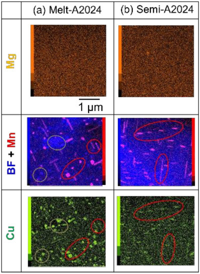
Figure 15.
X-ray mapping images by TEM-EDS: (a) Melt-A2024; (b) Semi-A2024.

Figure 16.
Number of T phases per unit area NT: (a) Melt-A2024; (b) Semi-A2024. The error bars show the standard deviations.
3.3.6. The Effect of the Difference of Nano-Sized Precipitates on Compressive Properties
There were some differences in nano-sized precipitate between Melt-A2024 and Semi-A2024. In this section, the entire effect of the nano-sized precipitate on compressive properties is summarized. First, the θ phase, which decreases the degree of age hardening, was found only in Melt-A2024, as explained in Section 3.3.5. (X-ray Diffraction). The number of T phases existing in the cell wall of Semi-A2024 was larger than that of Melt-A2024. As the S’ phase precipitates on the T phase, the total number of S’ phases that did not precipitate on the T phases decreased in Semi-A2024. This will cause the number of GPB zones, which contribute most to the strengthening, to increase owing to the decrease in the total number of S’ phases precipitating [18]. Therefore, in Semi-A2024, the total number of S’ phases is considered to decrease, so the total number of GPB zones is considered to increase. From the above, the suppression of θ/θ’ phase precipitation and the increase in GPB zone resulted in larger value of hardness in the cell walls of Semi-A2024. Therefore, the plateau stress of Semi-A2024 was larger than that of Melt-A2024. Moreover, Mg will diffuse in the S/S’ phase.
3.3.7. The Effect of the Difference in Pore Morphology and the Cell Wall Structure on Compressive Properties
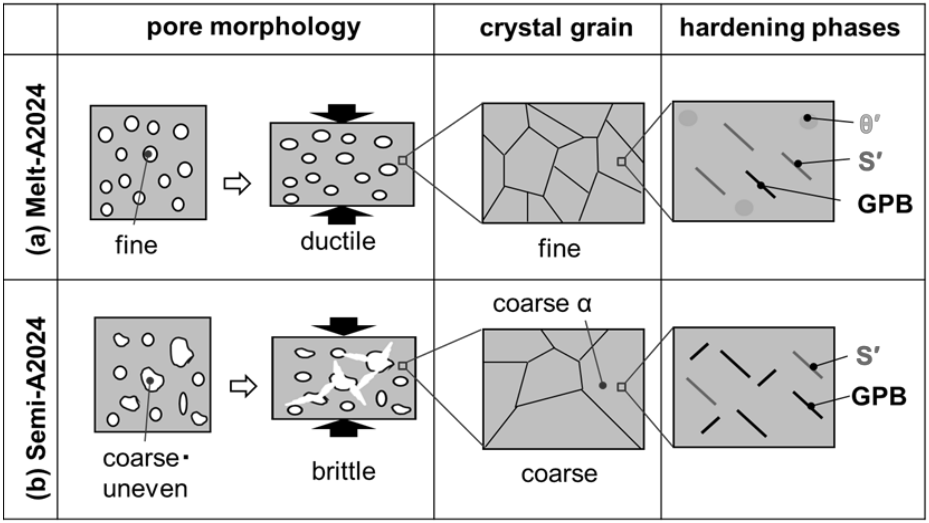
In this section, the whole effect of the difference in pore morphology and cell wall structure on the compressive property tendencies is explained. Figure 17 shows schematic drawings of the pore morphology and cell wall structure of (a) Melt-A2024 and (b) Semi-A2024. The fine pores of Melt-A2024 resulted in the ductile fracture of samples. Semi-A2024 includes coarser and more uneven pores than those of Melt-A2024. This resulted in a slightly brittle fracture of samples [12]. Therefore, the plateau area became flat, and the energy absorption efficiency became larger. However, Melt-A2024 has finer grains, whereas Semi-A2024 has coarser grains. Therefore, the effect of grain boundary strengthening is weaker than that in Melt-A2024. However, the θ/θ’ phase, which decreases the degree of age hardening, precipitates in Melt-A2024. In Melt-A2024, the total number of S’ phases will increase, causing the GPB zone to decrease. The θ/θ’ phase was suppressed in Semi-A2024. Thus, the S’ phase decreases and the GPB zone will increase. Therefore, the degree of age hardening of Semi-A2024 is larger than that of Melt-A2024. In the age hardening-type aluminum alloys, the precipitation effect will contribute more to the strength of cell walls than the effect of grain boundary strengthening [19]. Therefore, the hardness of cell walls of the Semi-A2024 alloy is larger than that of Melt-A2024.

Figure 17.
Schematic drawing of trend pore morphology and cell wall structure: (a) Melt-A2024; (b) Semi-A2024.
4. Conclusions
A2024 alloy foams were fabricated through the melt route at above the liquidus temperature (648 °C [9]) and through the semi-solid route in the range between the liquidus and solidus temperature (510 °C [9]). The effect of the differences in pore morphology and the cell wall structure on compressive properties was then clarified. The most important finding of this study is that A2024 alloy foams fabricated through the semi-solid route prevent the precipitation of the θ/θ’ phase and increase the participation amount of the GPB zone, leading to larger plateau stress σpl. The results can be summarized as follows.
- 1.
- A2024 alloy foams fabricated through the semi-solid route have coarse and uneven pores. The pores led to a slightly brittle fracture of the foams and may have resulted in larger energy absorption efficiency ηV.
- 2.
- A2024 alloy foams fabricated through the semi-solid route have a coarser grain size because of the coarse primary crystals. However, the prevention of the decrease in the alloying element Mg by excluding the long stirring for thickening suppressed the θ/θ’ phase and increased the number of GPB zones by preventing the precipitation amount of the S′ phase. This led to a larger plateau stress σpl.
Author Contributions
Writing—review and editing, T.K. and S.S.; conceptualization, T.O. and S.S.; methodology, T.O. and S.S.; validation, T.O. and S.S.; formal analysis, T.K., T.O., and S.S.; investigation, T.O.; data curation, T.O. and S.S.; writing—original draft preparation, T.K. and T.O.; visualization, T.O.; supervision, M.S. and S.S.; project administration, M.S. and S.S.
Funding
This study was supported by the Grant-in-Aid the Light Metal Educational Foundation.
Acknowledgments
The authors thank N. Sakaguchi from UACJ Corporation for supplying the A2024 ingots used in this study.
Conflicts of Interest
The authors declare no conflict of interest.
References
- Miyoshi, T.; Itoh, M.; Akiyama, S. ALPORAS Aluminum foam: Production process, properties, and applications. Adv. Eng. Mater. 2000, 2, 179–183. [Google Scholar] [CrossRef]
- Ueno, H.; Akiyama, S. Effects of calcium addition on the foamability of molten aluminum. J. Jpn. Inst. Light Met. 1987, 37, 42–47. [Google Scholar] [CrossRef]
- Hamada, T.; Nishi, S.; Miyoshi, T.; Kanetake, N. Effect of foaming condition in the melt on cell structure and compression strength of porous aluminum. J. Jpn. Inst. Met. 2008, 72, 825–831. [Google Scholar] [CrossRef]
- Fukui, T.; Saito, M.; Nonaka, Y.; Suzuki, S. Fabrication of foams of A2024 and A7075 and influence of porosity and heat treatment on their mechanical properties. Trans. Jpn. Soc. Mech. Eng. 2014, 80, 1–9. (In Japanese) [Google Scholar]
- Fukui, T.; Nonaka, Y.; Suzuki, S. Fabrication of Al-Cu-Mg alloy foams using Mg as thickener through melt route and reinforcement of cell walls. Procedia Mater. Sci. 2014, 4, 33–37. [Google Scholar] [CrossRef]
- Hamada, T.; Nishi, S.; Takagi, T.; Miyoshi, T.; Kanetake, N. Effect of alloy contents on the compression performances of porous aluminum by melt route. J. Jpn. Inst. Met. 2009, 2, 88–94. [Google Scholar] [CrossRef]
- Hanafusa, T.; Ohishi, K. Making of Porous Metallic Material by the Semi-Solid Aluminum Alloy; Report of Hiroshima Prefectural Technology Research Institute West Region Industrial Research Center; Hiroshima Prefectural Technology Research Institute West ern Region Industrial Research Center: Hiroshima, Japan, 2010; Volume 23, pp. 28–29. (In Japanese) [Google Scholar]
- Kuwahara, T.; Saito, M.; Osaka, T.; Suzuki, S. Effect of primary crystals on pore morphology during semi-solid foaming of A2024 alloys. Metals 2019, 9, 88. [Google Scholar] [CrossRef]
- Kim, W.Y.; Kang, C.G.; Lee, S.M. Effect of viscosity on microstructure characteristic in rheological behavior of wrought aluminum alloys by compression and stirring process. Mater. Sci. Technol. 2010, 26, 20–30. [Google Scholar] [CrossRef]
- Japan Aluminum Association. (Ed.). Physical property. In Aluminum Hand Book, 7th ed.; Japan Aluminum Association: Tokyo, Japan, 2007; p. 32. [Google Scholar]
- International Organization for Standardization (ISO). Mechanical Testing of Metals-Ductility Testing-Compression Test for Porous and Cellular Metals; ISO13314; ISO: Geneva, Switzerland, 2011; pp. 1–7. [Google Scholar]
- Kadar, M.A.; Islam, M.A.; Saadatfar, M.; Hazell, P.J.; Brown, A.D.; Ahmed, A.; Escobedo, J.P. Macro and micro collapse mechanisms of closed-cell aluminum foams during quasi-static compression. Mater. Des. 2017, 118, 11–21. [Google Scholar] [CrossRef]
- Zhang, X.; Hashimoto, T.; Lindsay, J.; Zhou, X. Investigation of the de-alloying behavior of θ-phase (Al2Cu) in AA2024-T351 aluminum alloy. Corros. Sci. 2016, 108, 85–93. [Google Scholar] [CrossRef]
- Kumaran, S.M. Identification of high temperature precipitation reactions in 2024 Al-Cu-Mg alloy through ultrasonic parameters. J. Alloys Compd. 2012, 539, 179–183. [Google Scholar] [CrossRef]
- Son, S.K.; Takeda, M.; Mitome, M.; Bando, Y.; Endo, T. Precipitation behavior of an Al-Cu alloy during isothermal aging at low temperatures. Mater. Lett. 2005, 59, 629–632. [Google Scholar] [CrossRef]
- Silcock, J.M. The Structural Ageing Characteristics of Al-Cu-Mg Alloys with Copper: Magnesium Weight Ratio of 7:1 and 2.2:1. J. Inst. Met. 1961, 89, 203–210. [Google Scholar]
- Chen, Y.Q.; Pan, S.P.; Liu, W.H.; Liu, X.; Tang, C.P. Morphologies, orientation relationships, and evolution of the T-phase in an Al-Cu-Mg-Mn alloy during homogenisation. J. Alloys Compd. 2017, 709, 213–226. [Google Scholar] [CrossRef]
- Kanno, M.; Suzuki, H.; Itoi, K. The effects of zirconium addition on aging phenomena of Al-Cu-Mg alloy. J. Jpn. Inst. Light Met. 1986, 36, 616–621. [Google Scholar] [CrossRef]
- Ono, N.; Gouya, J.; Miura, S. Hall-Petch Relation and strengthening mechanisms in Al-Zn-Mg-Cu alloy polycrystals. Trans. Jpn. Soc. Mech. Eng. 2002, 68, 138–144. (In Japanese) [Google Scholar] [CrossRef]


© 2019 by the authors. Licensee MDPI, Basel, Switzerland. This article is an open access article distributed under the terms and conditions of the Creative Commons Attribution (CC BY) license (http://creativecommons.org/licenses/by/4.0/).