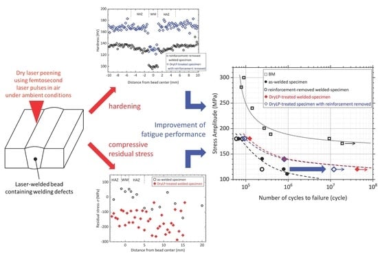
Improving Fatigue Performance of Laser-Welded 2024-T3 Aluminum Alloy Using Dry Laser Peening

 ,
, 

Abstract
1. Introduction
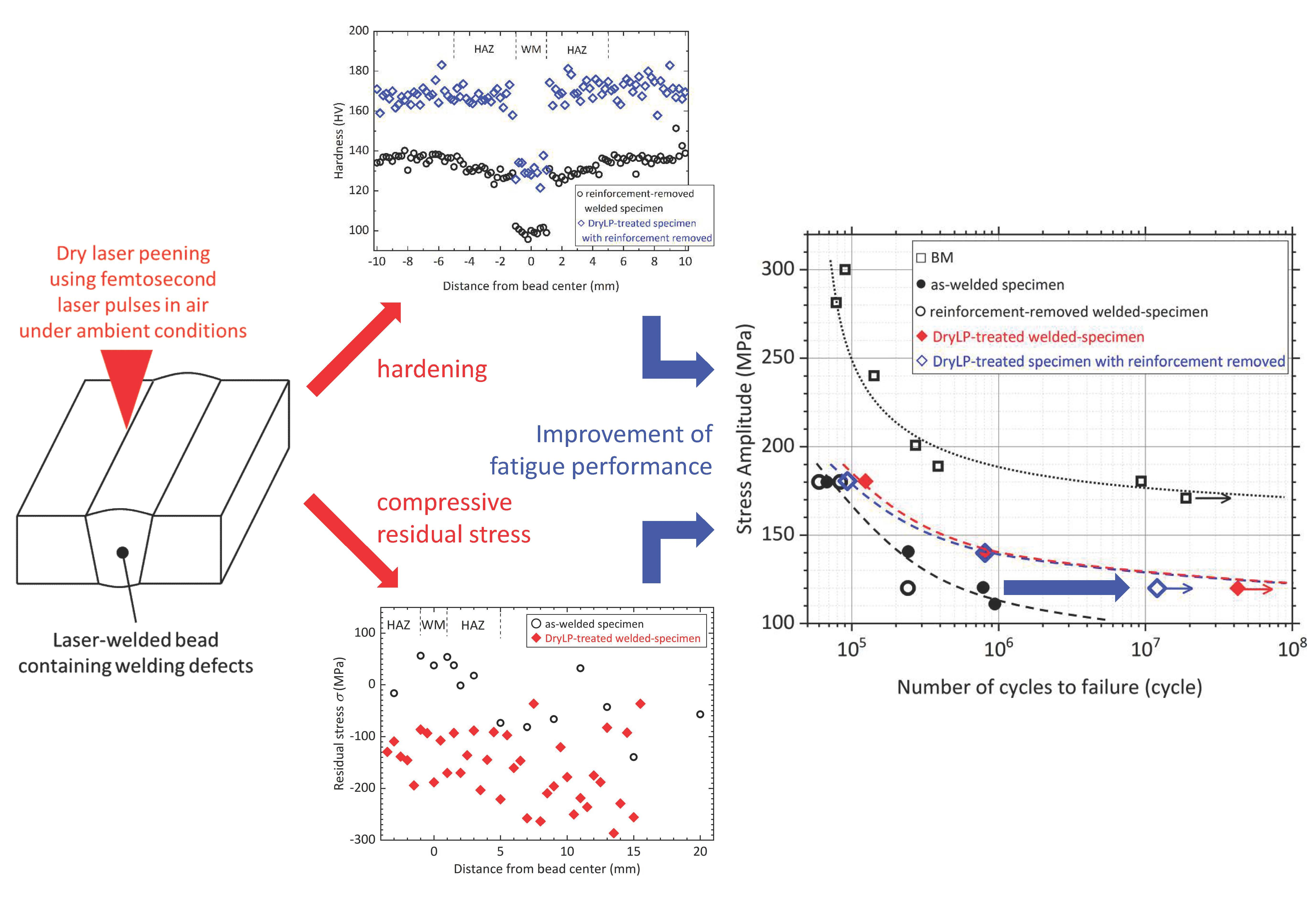
2. Experimental Method
3. Results and Discussion
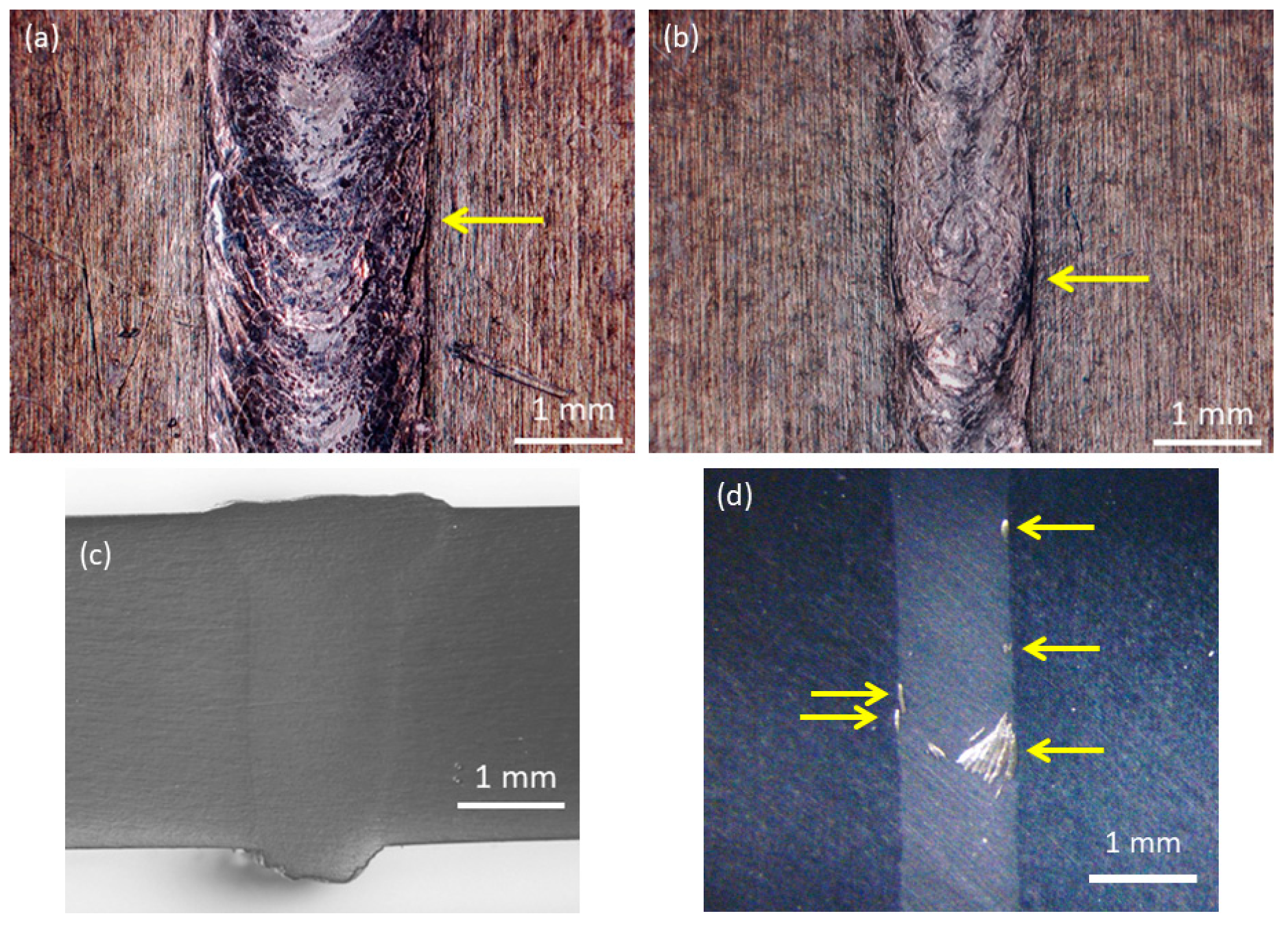
3.1. Laser Welding
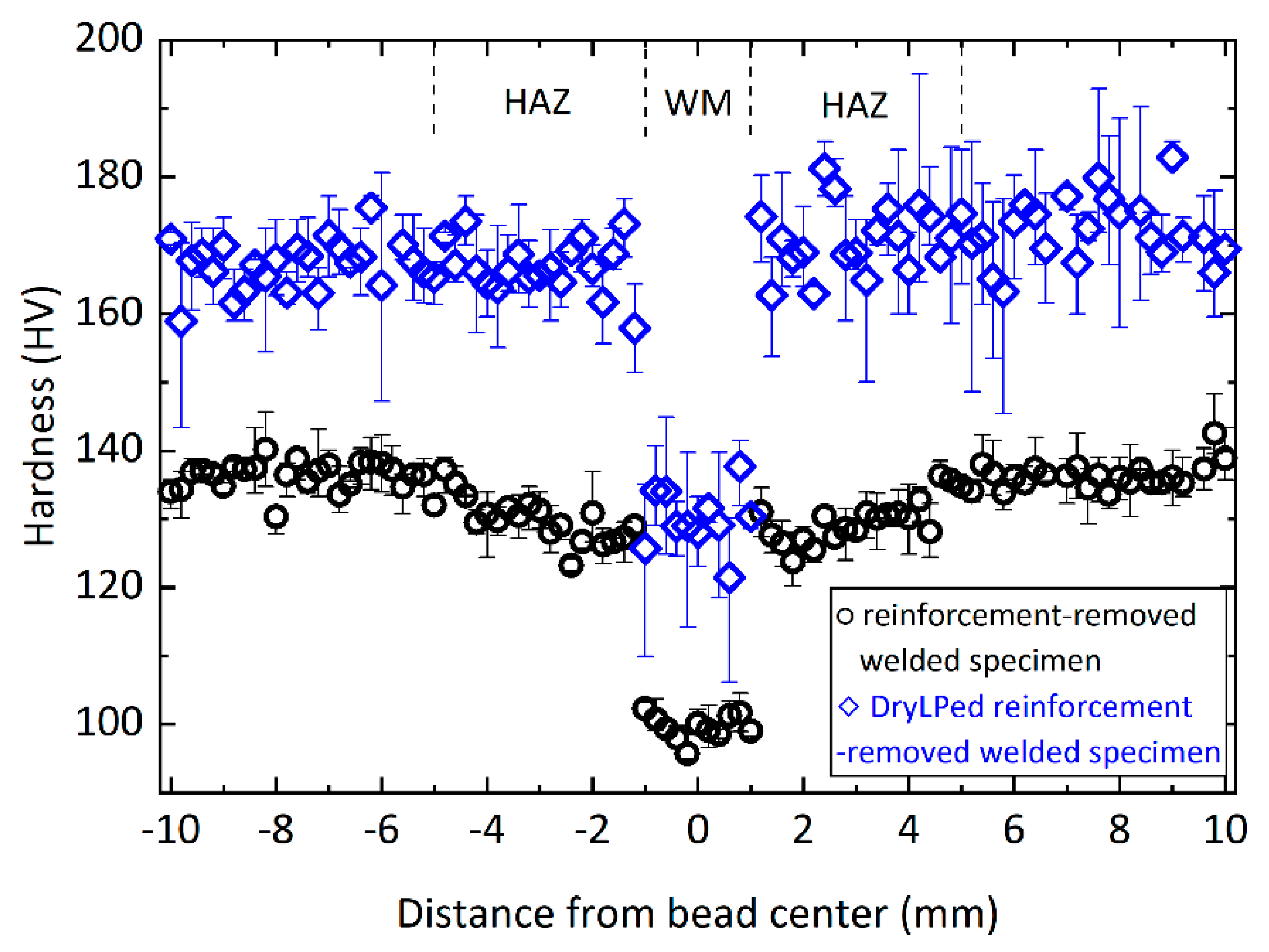
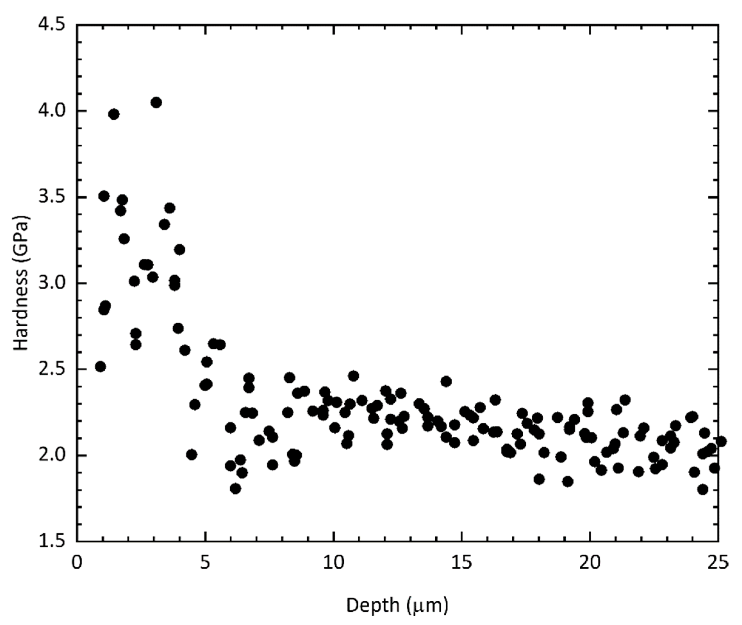
3.2. Hardness
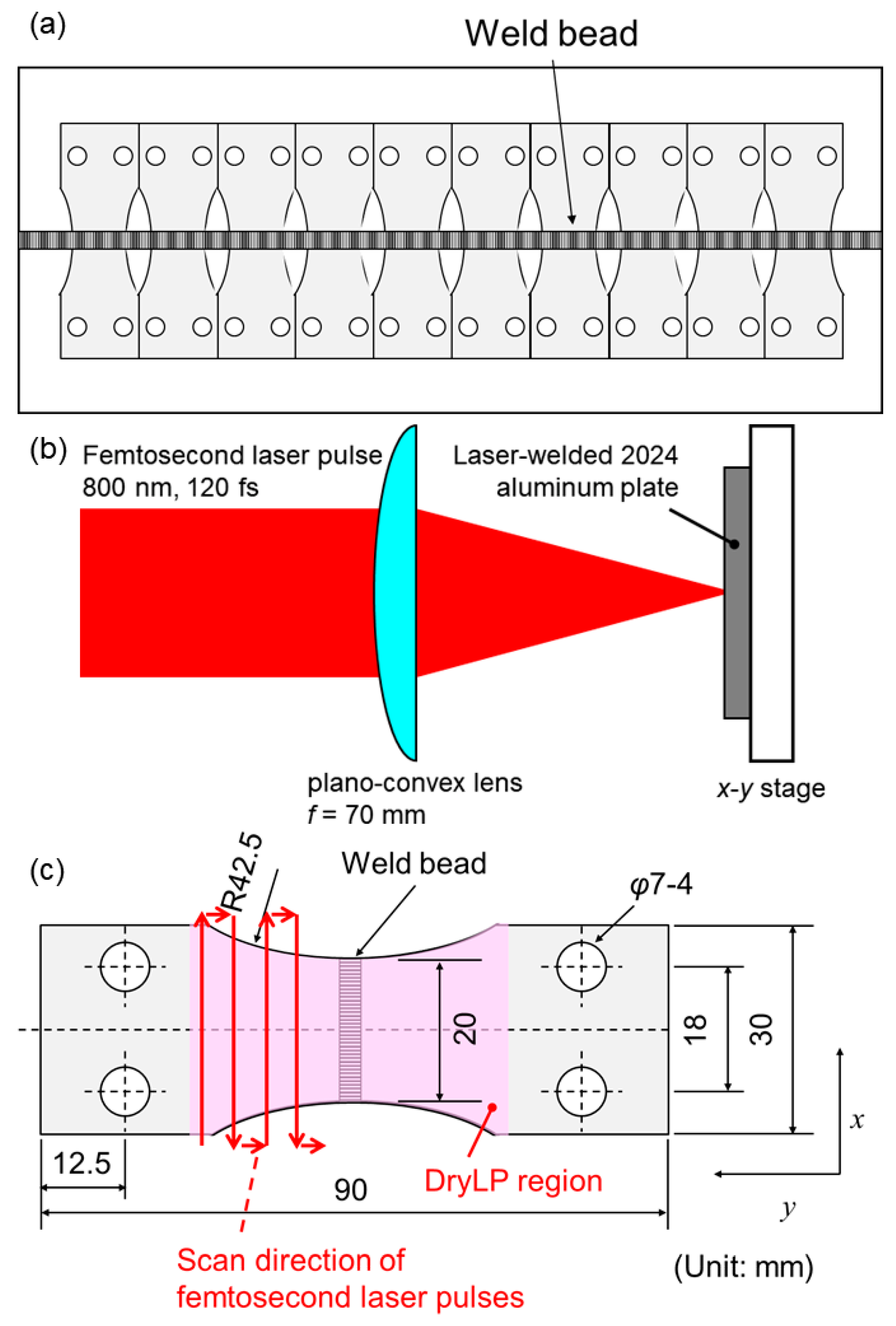
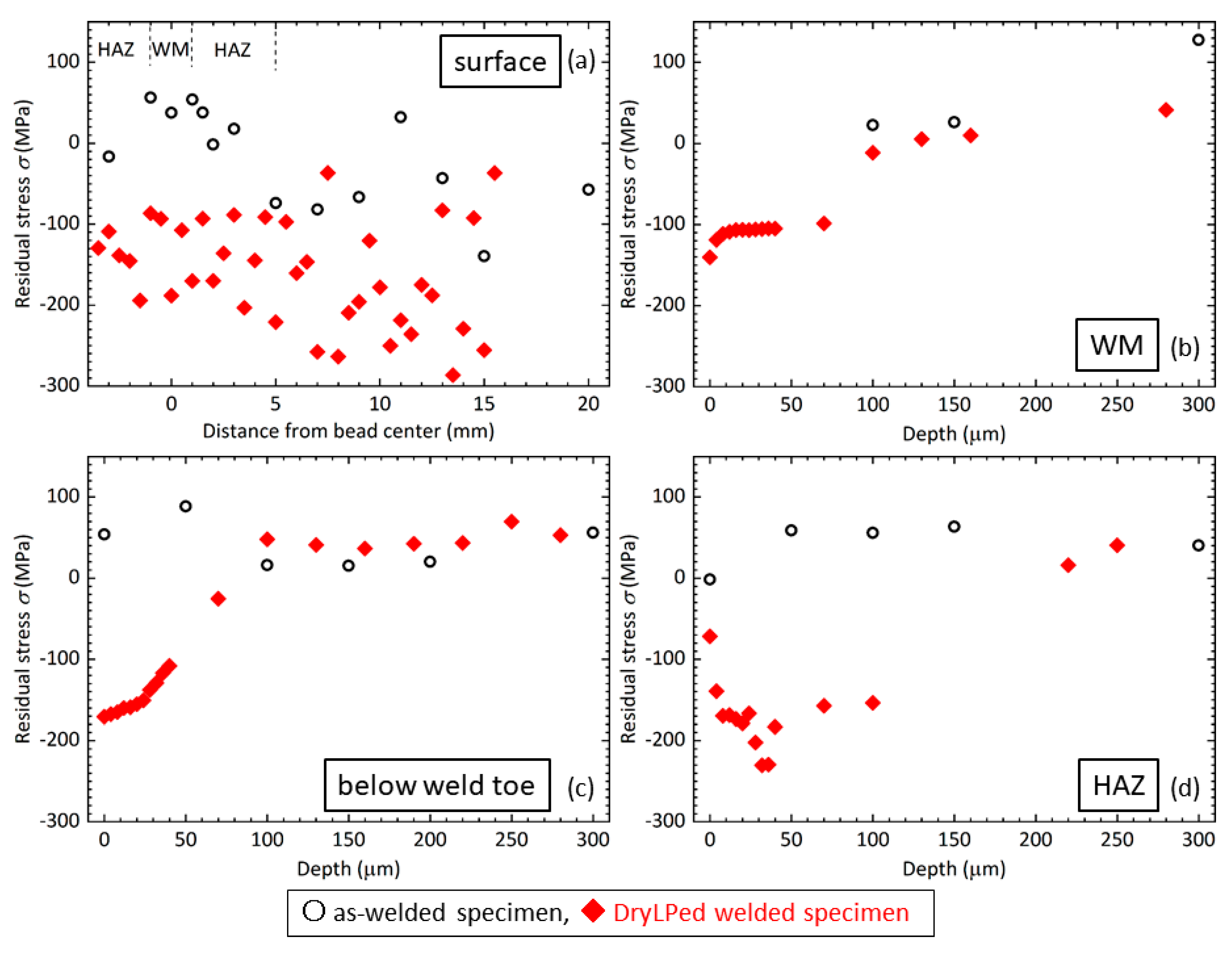
3.3. Residual Stress
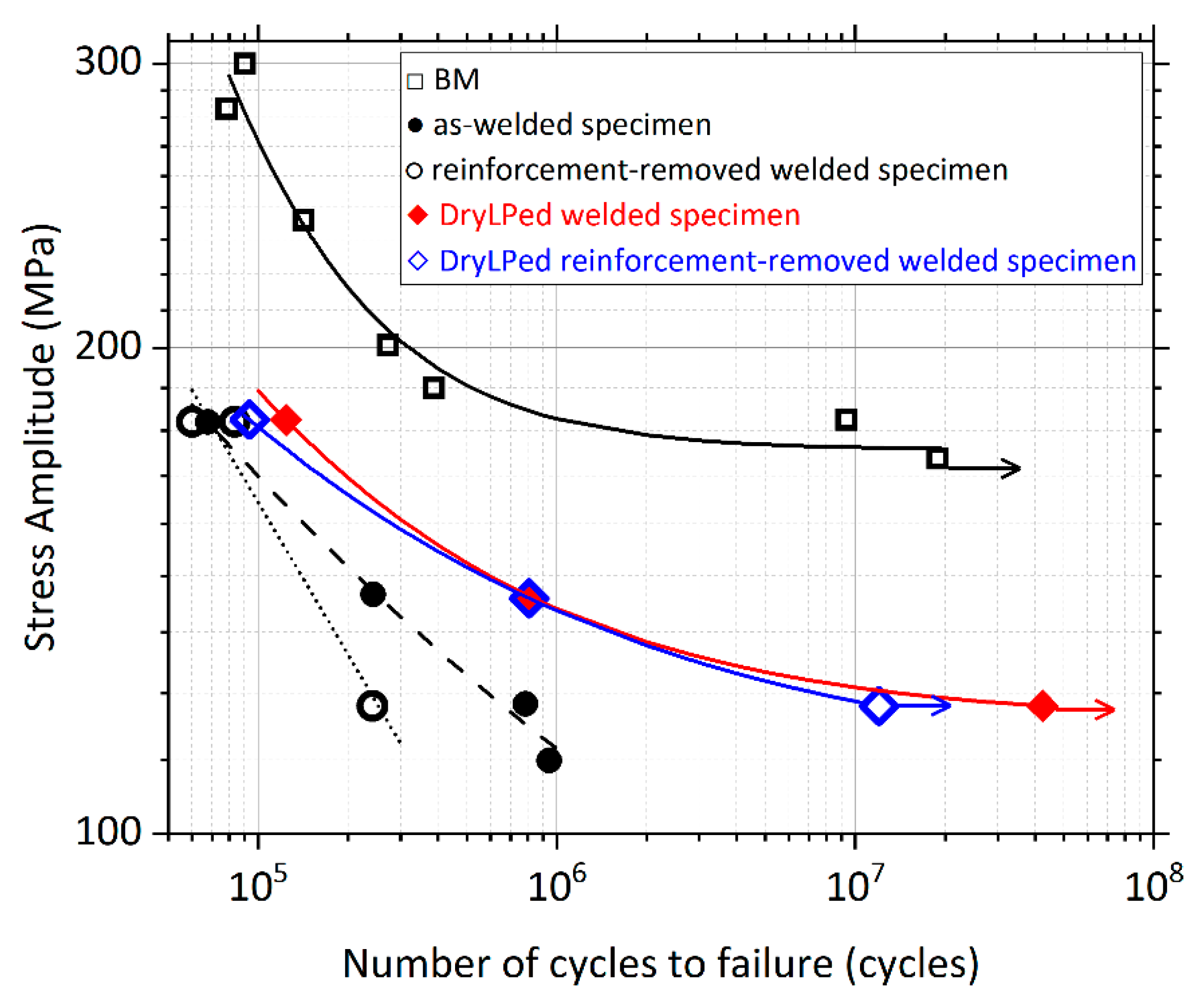
3.4. Fatigue Performance
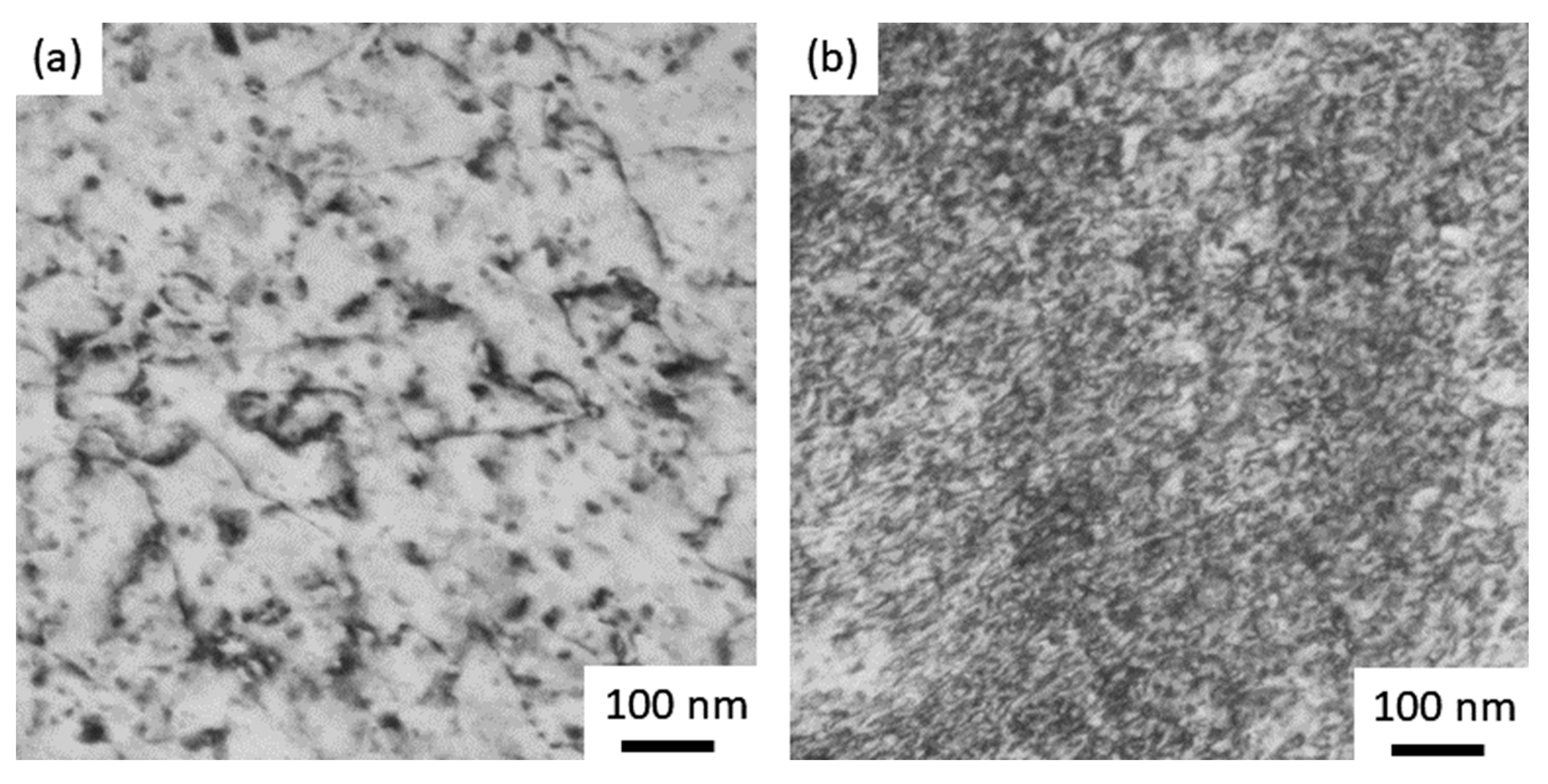
3.5. Microstructure in WM
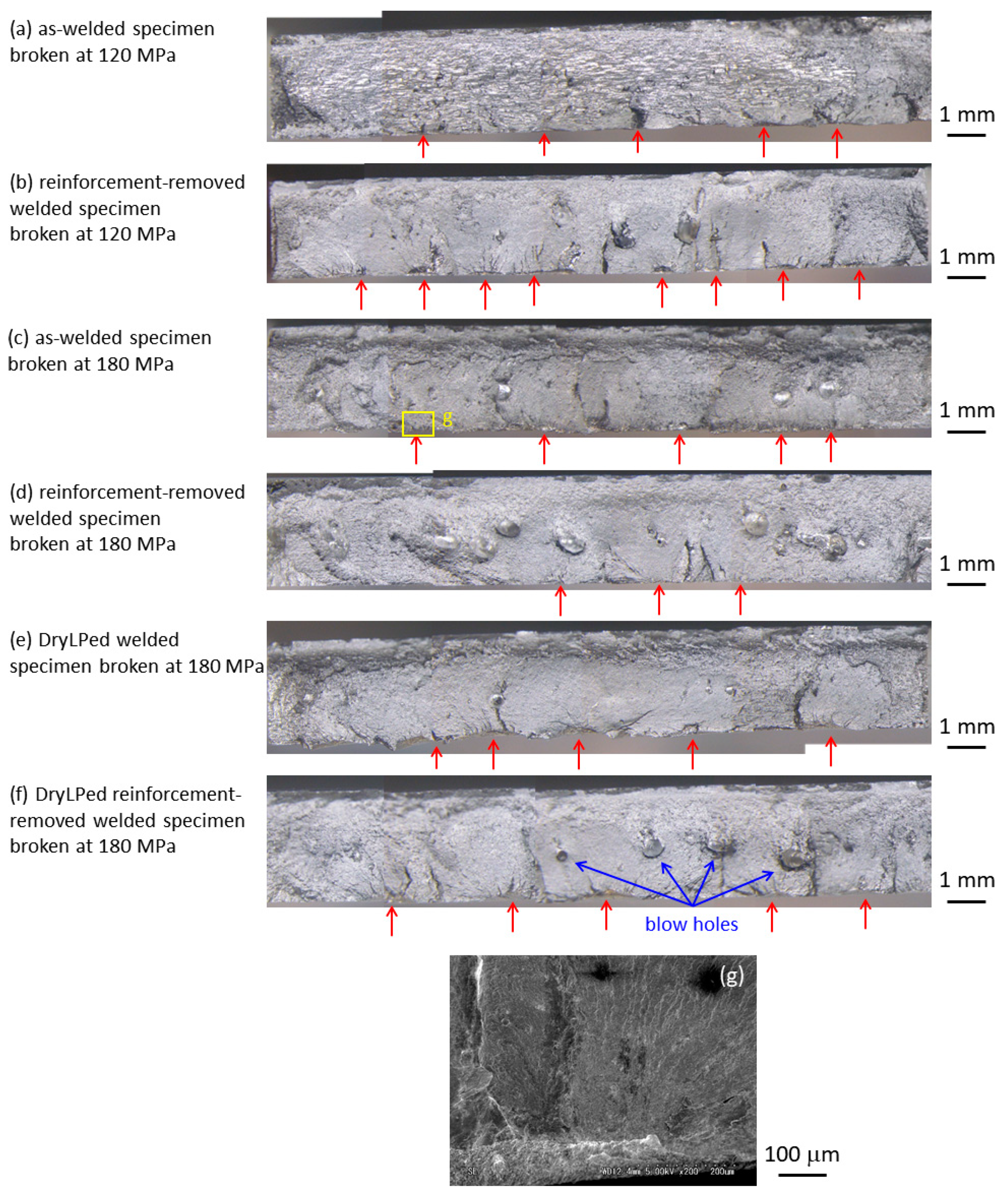
3.6. Effect of Welding Defects on Fatigue Performance
3.7. Plastic Deformation Induced by Femtosecond Laser-Driven Shock Wave
4. Conclusions
Author Contributions
Funding
Acknowledgments
Conflicts of Interest
References
- Anderholm, N.C. Laser-generated stress waves. Appl. Phys. Lett. 1970, 16, 113–115. [Google Scholar] [CrossRef]
- Fairand, P.; Wilcox, B.A.; Gallagher, W.J.; Williams, D.N. Laser shock-induced microstructural and mechanical property changes in 7075 aluminum. J. Appl. Phys. 1972, 43, 3893–3895. [Google Scholar] [CrossRef]
- Clauer, A.H. Laser Shock Peening, the Path to Production. Metals 2019, 9, 626. [Google Scholar] [CrossRef]
- Fabbro, R.; Peyre, P.; Berthe, L.; Scherpereel, X. Physics and applications of laser-shock processing. J. Laser Appl. 1998, 10, 265–279. [Google Scholar] [CrossRef]
- Montross, C.S.; Wei, T.; Ye, L.; Clark, G.; Mai, Y.W. Laser shock processing and its effects on microstructure and properties of metal alloys: A review. Int. J. Fatigue 2002, 24, 1021–1036. [Google Scholar] [CrossRef]
- Tenaglia, R.D.; Lahrman, D.F. Shock tactics. Nat. Photonics 2009, 3, 267–269. [Google Scholar] [CrossRef]
- Sano, Y.; Mukai, N.; Okazaki, K.; Obata, M. Residual stress improvement in metal surface by underwater laser irradiation. Nucl. Instrum. Methods B 1997, 121, 432–436. [Google Scholar] [CrossRef]
- Sano, Y.; Obata, M.; Kubo, T.; Mukai, N.; Yoda, M.; Masaki, K.; Ochi, Y. Retardation of crack initiation and growth in austenitic stainless steels by laser peening without protective coating. Mater. Sci. Eng. A 2006, 417, 334–340. [Google Scholar] [CrossRef]
- Sano, T.; Eimura, T.; Kashiwabara, R.; Matsuda, T.; Isshiki, Y.; Hirose, A.; Tsutsumi, S.; Arakawa, K.; Hashimoto, T.; Masaki, K.; et al. Femtosecond laser peening of 2024 aluminum alloy without a sacrificial overlay under atmospheric conditions. J. Laser Appl. 2017, 29, 012005. [Google Scholar] [CrossRef]
- Kawashima, T.; Sano, T.; Hirose, A.; Tsutsumi, S.; Masaki, K.; Arakawa, K.; Hori, H. Femtosecond laser peening of friction stir welded 7075-T73 aluminum alloys. J. Mater. Process. Technol. 2018, 262, 111–122. [Google Scholar] [CrossRef]
- Trdan, U.; Sano, T.; Klobčara, D.; Sano, Y.; Grum, J.; Šturm, R. Improvement of corrosion resistance of AA2024-T3 using femtosecond laser peening without protective and confining medium. Corros. Sci. 2018, 143, 46–55. [Google Scholar] [CrossRef]
- Strickland, D.; Mourou, G. Compression of amplified chirped optical pulses. Opt. Commun. 1985, 56, 219–221. [Google Scholar] [CrossRef]
- Evans, R.; Badger, A.D.; Falliès, F.; Mahdieh, M.; Hall, T.A.; Audebert, P.; Geindre, J.-P.; Gauthier, J.-C.; Mysyrowicz, A.; Grillon, G.; et al. Time- and space-resolved optical probing of femtosecond-laser-driven shock waves in aluminum. Phys. Rev. Lett. 1996, 77, 3359–3362. [Google Scholar] [CrossRef] [PubMed]
- Sano, T.; Mori, H.; Ohmura, E.; Miyamoto, I. Femtosecond laser quenching of the ε phase of iron. Appl. Phys. Lett. 2003, 83, 3498–3500. [Google Scholar] [CrossRef]
- Tsujino, M.; Sano, T.; Sakata, O.; Ozaki, N.; Kimura, S.; Takeda, S.; Okoshi, M.; Inoue, N.; Kodama, R.; Kobayashi, K.F.; et al. Synthesis of submicron metastable phase of silicon using femtosecond laser-driven shock wave. J. Appl. Phys. 2011, 110, 126103. [Google Scholar] [CrossRef]
- Tsujino, M.; Sano, T.; Ogura, T.; Okoshi, M.; Inoue, N.; Ozaki, N.; Kodama, R.; Kobayashi, K.F.; Hirose, A. Formation of high-density dislocations and hardening in femtosecond-laser-shocked silicon. Appl. Phys. Express 2012, 5, 022703. [Google Scholar] [CrossRef]
- Matsuda, T.; Sano, T.; Arakawa, K.; Hirose, A. Multiple-shocks induced nanocrystallization in iron. Appl. Phys. Lett. 2014, 105, 021902. [Google Scholar] [CrossRef]
- Matsuda, T.; Sano, T.; Arakawa, K.; Hirose, A. Dislocation structure produced by an ultrashort shock pulse. J. Appl. Phys. 2014, 116, 183506. [Google Scholar] [CrossRef]
- Matsuda, T.; Sano, T.; Arakawa, K.; Sakata, O.; Tajiri, H.; Hirose, A. Femtosecond laser-driven shock-induced dislocation structures in iron. Appl. Phys. Express 2014, 7, 122704. [Google Scholar] [CrossRef]
- DeWald, A.T.; Rankin, J.E.; Hill, M.R.; Lee, M.J.; Chen, H.L. Assessment of tensile residual stress mitigation in alloy 22 welds due to laser peening. J. Eng. Mater. Technol. 2004, 126, 465–473. [Google Scholar] [CrossRef]
- Hatamleh, O.; Lyons, J.; Forman, R. Laser and shot peening effects on fatigue crack growth in friction stir welded 7075-T7351 aluminum alloy joints. Int. J. Fatigue 2007, 29, 421–434. [Google Scholar] [CrossRef]
- Hatamleh, O. A comprehensive investigation on the effects of laser and shot peening on fatigue crack growth in friction stir welded AA 2195 joints. Int. J. Fatigue 2009, 31, 974–988. [Google Scholar] [CrossRef]
- Sano, Y.; Masaki, K.; Gushi, T.; Sano, T. Improvement in fatigue performance of friction stir welded A6061-T6 aluminum alloy by laser peening without coating. Mater. Des. 2012, 36, 809–814. [Google Scholar] [CrossRef]
- Bussu, G.; Irving, P.E. The role of residual stress and heat affected zone properties on fatigue crack propagation in friction stir welded 2024-T351 aluminium joints. Int. J. Fatigue 2003, 25, 77–88. [Google Scholar] [CrossRef]
- Liljedahl, C.D.M.; Brouard, J.; Zanellato, O.; Lin, J.; Tan, M.L.; Ganguly, S.; Irving, P.E.; Fitzpatrick, M.E.; Zhang, X.; Edwards, L. Weld residual stress effects on fatigue crack growth behaviour of aluminium alloy 2024-T351. Int. J. Fatigue 2009, 31, 1081–1088. [Google Scholar] [CrossRef]
- Nandan, R.; DebRoy, T.; Bhadeshia, H.K.D.H. Recent advances in friction-stir welding—Process, weldment structure and properties. Prog. Mater. Sci. 2008, 53, 980–1023. [Google Scholar] [CrossRef]
- Kulekci, C.; Ik, A.S.; Kaluc, E. Effects of tool rotation and pin diameter on fatigue properties of friction stir welded lap joints. Int. J. Adv. Manuf. Technol. 2008, 36, 877–882. [Google Scholar] [CrossRef]
- Garware, M.; Kridli, G.T.; Mallick, P.K. Tensile and fatigue behavior of friction-stir welded tailor-welded blank of aluminum alloy 5754. J. Mater. Eng. Perform. 2010, 19, 1161–1171. [Google Scholar] [CrossRef]
- Dursun, T.; Soutis, C. Recent developments in advanced aircraft aluminium alloys. Mater. Des. 2014, 56, 862–871. [Google Scholar] [CrossRef]
- Schubert, E.; Klassen, M.; Zerner, I.; Walz, C.; Sepold, G. Light-weight structures produced by laser beam joining for future applications in automobile and aerospace industry. J. Mater. Process. Technol. 2001, 115, 2–8. [Google Scholar] [CrossRef]
- Katayama, S.; Nagayama, H.; Mizutani, M.; Kawahito, Y. Fibre laser welding of aluminium alloy. Weld. Int. 2009, 23, 744–752. [Google Scholar] [CrossRef]
- Shobu, T.; Tozawa, K.; Shiwaku, H.; Konishi, H.; Inami, T.; Harami, T.; Mizuki, J. Wide band energy beamline using Si (111) crystal monochromators at BL22XU in SPring-8. AIP Conf. Proc. 2007, 879, 902–906. [Google Scholar] [CrossRef]
- Shobu, T.; Konishi, H.; Mizuki, J.; Suzuki, K.; Suzuki, H.; Akiniwa, Y.; Tanaka, K. Evaluation of subsurface distribution of residual stress in austenitic stainless steel using strain scanning method. Mater. Sci. Forum 2006, 524, 691–696. [Google Scholar] [CrossRef]
- Little, R.E. Estimating the median fatigue limit for very small up-and-down quantal response tests and for S-N data with runouts. In Probabilistic Aspects of Fatigue; Heller, R., Ed.; ASTM International: West Conshohocken, PA, USA, 1972; pp. 29–42. [Google Scholar]
- Ahn, J.; Chenb, L.; Heb, E.; Daviesa, C.M.; Deara, J.P. Effect of filler metal feed rate and composition on microstructure and mechanical properties of fibre laser welded AA 2024-T3. J. Manuf. Process. 2017, 25, 26–36. [Google Scholar] [CrossRef]
- Ahn, J.; Heb, E.; Chenb, L.; Deara, J.; Daviesa, C. The effect of Ar and He shielding gas on fibre laser weld shape and microstructure in AA 2024-T3. J. Manuf. Process. 2017, 29, 62–73. [Google Scholar] [CrossRef]
- Hu, B.; Richardson, I.M. Autogenous laser keyhole welding of aluminum alloy 2024. J. Laser Appl. 2005, 17, 70–80. [Google Scholar] [CrossRef]
- Cross, C.E.; Olson, D.L.; Liu, S. Aluminium Welding, Handbook of Aluminum; Dekker: New York, NY, USA, 2003; Volume 1. [Google Scholar]
- Keh, A.S. Direct Observation of Imperfection in Crystals; Interscience Publishers: New York, NY, USA, 1962; pp. 213–233. [Google Scholar]
- Kim, D.Y.; Hwang, I.; Jeong, G.; Kang, M.; Kim, D.; Seo, J.; Kim, Y.M. Effect of Porosity on the Fatigue Behavior of Gas Metal ArcWelding Lap Fillet Joint in GA 590 MPa Steel Sheets. Metals 2018, 8, 241. [Google Scholar] [CrossRef]
- Crowhurst, J.C.; Armstrong, M.R.; Knight, K.B.; Zaug, J.M.; Behymer, E.M. Invariance of the Dissipative Action at Ultrahigh Strain Rates Above the Strong Shock Threshold. Phys. Rev. Lett. 2011, 107, 144302. [Google Scholar] [CrossRef]
- Ashitkov, S.I.; Agranat, M.B.; Kanel, G.I.; Komarov, P.S.; Fortov, V.E. Behavior of Aluminum near an Ultimate Theoretical Strength in Experiments with Femtosecond Laser Pulses. JETP Lett. 2010, 92, 516–520. [Google Scholar] [CrossRef]
- Swegle, J.W.; Grady, D.E. Shock viscosity and the prediction of shock wave rise times. J. Appl. Phys. 1985, 58, 692–701. [Google Scholar] [CrossRef]
- Grady, D.E. Structured shock waves and the fourth-power law. J. Appl. Phys. 2010, 107, 013506. [Google Scholar] [CrossRef]
- McQueen, R.G.; March, S.P.; Taylor, J.W.; Fritz, J.N.; Carter, W.J. High.-Velocity Impact Phenomena; Kinslow, R., Ed.; Academic: New York, NY, USA, 1970; p. 293. [Google Scholar]
- Meyers, M.A. A mechanism for dislocation generation in shock-wave deformation. Scr. Metall. 1978, 12, 21–26. [Google Scholar] [CrossRef]


| Si | Fe | Cu | Mn | Mg | Cr | Zn | Ti | Others | Al |
|---|---|---|---|---|---|---|---|---|---|
| 0.02 | 0.05 | 4.4 | 0.55 | 1.4 | 0.00 | 0.02 | 0.01 | 0.01 | Bal. |
© 2019 by the authors. Licensee MDPI, Basel, Switzerland. This article is an open access article distributed under the terms and conditions of the Creative Commons Attribution (CC BY) license (http://creativecommons.org/licenses/by/4.0/).
Share and Cite
Sano, T.; Eimura, T.; Hirose, A.; Kawahito, Y.; Katayama, S.; Arakawa, K.; Masaki, K.; Shiro, A.; Shobu, T.; Sano, Y. Improving Fatigue Performance of Laser-Welded 2024-T3 Aluminum Alloy Using Dry Laser Peening. Metals 2019, 9, 1192. https://doi.org/10.3390/met9111192
Sano T, Eimura T, Hirose A, Kawahito Y, Katayama S, Arakawa K, Masaki K, Shiro A, Shobu T, Sano Y. Improving Fatigue Performance of Laser-Welded 2024-T3 Aluminum Alloy Using Dry Laser Peening. Metals. 2019; 9(11):1192. https://doi.org/10.3390/met9111192
Chicago/Turabian StyleSano, Tomokazu, Takayuki Eimura, Akio Hirose, Yosuke Kawahito, Seiji Katayama, Kazuto Arakawa, Kiyotaka Masaki, Ayumi Shiro, Takahisa Shobu, and Yuji Sano. 2019. "Improving Fatigue Performance of Laser-Welded 2024-T3 Aluminum Alloy Using Dry Laser Peening" Metals 9, no. 11: 1192. https://doi.org/10.3390/met9111192
APA StyleSano, T., Eimura, T., Hirose, A., Kawahito, Y., Katayama, S., Arakawa, K., Masaki, K., Shiro, A., Shobu, T., & Sano, Y. (2019). Improving Fatigue Performance of Laser-Welded 2024-T3 Aluminum Alloy Using Dry Laser Peening. Metals, 9(11), 1192. https://doi.org/10.3390/met9111192