1. In-Use Properties of Advanced Bainitic Steels
Bainitic microstructures might offer an inexpensive solution for application to bearings, based on their interesting combination of fatigue and wear resistance [
1]. Considerable progress has been made since the early bainitic steels. The addition of Si, in particular, has allowed for the suppression of cementite, giving an ultra-fine microstructure, consisting of an intricate mixture of bainitic ferrite and austenite. High silicon bainitic steels, usually referred to as carbide-free bainitic steels, attain excellent strength–toughness combinations (up to 1700 MPa and 130 MPa·m
1/2), comparable to considerably more expensive high Ni maraging steels [
2,
3], and have higher wear resistance than pearlitic and conventional tempered martensitic steels [
4,
5,
6,
7].
Carbide-free bainitic steels derive their strength essentially from their ultra-fine grain size, with typical plate thickness being below 1 μm. Recent advances in the understanding of the bainitic transformation have been exploited to refine bainitic structures to the nano-scale by austempering at low temperatures (125–350 °C) and through careful alloy design [
8]. The further grain refinement allowed some to achieve unforeseen combinations of strength and toughness (up to 2500 MPa and 40 MPa·m
1/2) in economical steel grades [
9,
10,
11].
This low-temperature bainite reaction results in a nano-scale ferritic structure with a hardness that has never been achieved before in bainitic steels (>700 HV). Much of the strength and hardness of the structure comes from the extremely thin platelets of bainitic ferrite, but also dislocation forests and solution strengthening. It is known from X-ray diffraction (XRD) analyses and confirmed by atom probe tomography (APT) that bainitic ferrite contains much more carbon in solid solution than it is consistent with paraequilibrium thermodynamics conditions [
12,
13,
14,
15].
The different strength-ductility combinations observed in nanostructured bainite are associated with the stress and strain-induced martensitic transformation of retained austenite during tensile testing [
9,
11,
16,
17,
18,
19,
20]. Additionally, the formation of twins in austenite films has been identified as a strain hardening mechanism contributing to ductility in these structures [
20].
Complex properties, such as wear resistance and fatigue endurance, must be also assessed before the commercialization of novel bainitic steels. Earlier work [
4,
5] showed that the wear resistance of carbide-free bainitic steels was comparable to that of the best pearlitic grades. In the context of rail applications, Chang [
6] investigated the rolling/sliding wear performance of several high silicon bainitic steels, along with detailed microstructural characterization. Results showed lower wear rates in carbide-free bainitic steels and a beneficial effect of the austenite embedded in the sub-micron ferritic structure. In fact, Zhang et al. [
21] found that high silicon bainitic steels show better wear resistance than much harder martensite. Likewise, Yang et al. [
22] observed that material performance improved when the transformation temperature decreased and a nano-scale bainitic structure was formed.
These studies hint at the considerable benefits of nanostructured bainite against several wear and surface damage mechanisms [
7,
23,
24]. Retained austenite is considered to be critical for improving wear resistance in these structures, since this phase provides hardening by transformation into martensite [
23,
25]. It is well-known that hardness affects the stress needed to deform the material in the rolling/sliding contact, and it is an important factor in decreasing material loss. Wang et al. [
26] found that the austenite in the vicinity of a sliding surface decomposes under the influence of high shear strains, resulting in the formation of an extremely fine structure with grains of ferrite only about 3 nm in size.
Rolling contact fatigue (RCF) has also been determined to be a key mechanism of material removal in the wear performance of nanostructured bainite under rolling/sliding conditions [
23,
27]. Adhesive forces at the surface are crucial in generating crack initiation sites for RCF cracks. The microstructure was shown to lineate along the sliding direction, establishing preferential paths for cracks to grow along.
The RCF performance of nanostructured bainitic steels, of paramount importance in the context of bearings, has rarely been studied. Liu et al. [
28] suggested that nanostructured bainite could prolong the RCF life by effectively retarding crack initiation and propagation in a microstructure composed of nanostructured bainite, martensite, and undissolved primary carbides, with a hardness on par with commercial bearing steels (650–800 HV). However, the specific role of the different constituents was not addressed, and the structures observed were not uniform. Later work by Solano-Alvarez et al. [
29] showed that the RCF damage in nanostructured bainitic steels is quite different from that observed in conventional bearing steels. In particular, the formation of voids was prominent at interfaces between regions of bainitic ferrite and martensite, originating from the strain-induced transformation of the austenite blocks. Although void formation was identified as the key mechanism of damage evolution, cracks formed by the linking of voids generally exhibit considerable branching, delaying final fracture.
Further work is required to assess the failure mechanisms and to compare the RCF lives of advanced bainitic steels against conventional bearing steels. In this work, bearing components have been manufactured with a new steel grade, specially designed to transform to nanostructured bainite containing certain amount of austenite, and tested in comparison to reference grade 100Cr6 under severe rolling conditions, such as artificial pollution. Based on industrial trials, it was found that nanostructured bainitic grades offer a competitive solution in the application of bearings.
2. The Design and Manufacturing of Advanced Bainitic Steels for Bearing Components
A bearing is composed of inner and outer steel rings and rotating balls separated by a cage. The materials from the rings and balls are subjected to cyclic loading and unloading, leading to rolling contact fatigue. In case of good lubrication conditions, the cyclic shear stresses are mainly located in the subsurface. A crack can initiate, on a defect acting as a stress raiser, often non-metallic inclusions. When the crack propagates to the surface, a spalling occurs and leads to the bearing failure, as illustrated in
Figure 1. In case of severe operating conditions (deficient lubrication, contaminated lubrication, etc.), shear stresses also occur close to the surface and may lead to a surface-initiated crack, pitting, and spalling.
The typical specifications of bearing steels required to resist rolling contact fatigue, are listed in
Table 1 based on the properties of 100Cr6 steel after quenching and tempering at 170 °C, a commercial material commonly used in this application. Moreover, cleanliness and thermal stability are vital in bearing steels due to the strict requirements in terms of fatigue resistance.
Comparing the properties of nanostructured bainitic steels recently reviewed elsewhere [
31] with the industrial specifications of commercial bearing steels (
Table 1), a new alloy was designed applying displacive transformation fundaments to ensure low bainite reaction temperatures by using a high carbon content (1.0 wt.%), the prevention of cementite precipitation from austenite by high silicon additions (1.25 wt.%), and finally, improving hardenability and limited transformation times by an optimum combination of manganese and chromium additions, as
Table 2 shows, together with the former alloying developments.
The new material was manufactured as bars after an industrial assessment of feasibility and ensuring high cleanliness for bearing applications. Bars were spheroidized with the exception of 38 mm diameter bars, which were delivered for prototype manufacturing. The hardness of the as-received material was measured to be 230 HV30.
It is well known that this new generation of steels exhibits relatively slow transformation kinetics during bainite reaction [
8,
32]. Among all the alloying elements, carbon has the strongest effect of retarding bainite formation. In this sense, low austenitization temperatures without full solution of the spheroidized carbides were used prior to bainite transformation. This way, the amount of carbon in the austenite matrix is lower than the nominal, leading to heat treatment times more realistically applicable at an industrial scale. Therefore, different austenitising and bainite transformation conditions were investigated by dilatometry, as
Table 3 illustrates.
For that purpose, a Bahr DIL 805D high-resolution dilatometer (TA Instruments, New Castle, DE, USA) and cylindrical samples 4 mm in diameter and 10 mm in length were used. During dilatometry measurements, the specimen is held between two quartz rods, one fixed and the other connected to a linear variable displacement transducer (LVDT). Thus, during austempering heat treatment, it was possible to monitor bainite reaction by measuring the relative change in length of the sample. The time to end bainite transformation is identified at the time at which the dilatation signal reaches a steady-state, and transformation does not proceed any further.
Transformation time values in
Table 3 suggest that an increase in the austenitising temperature results in higher transformation times and lower final hardness for the same transformation temperature. Nevertheless, higher austenitising temperatures lead to higher fractions of retained austenite in the final microstructure, due to a higher carbon content in the parent austenite. On the other hand, comparing results obtained at 220, 250, and 270 °C for an austenitising temperature of 860 °C, the primary importance of transformation temperature for the resulting hardness is clearly shown.
After this preliminary study, three different treatments, austempering, quenching and partitioning (Q&P), and quenching and tempering (Q&T), with identical austenitizing conditions (900 °C for 30 min) were applied to obtain bainitic and martensitic structures containing a substantial amount of retained austenite in the designed steel.
Figure 2 schematizes the applied heat treatment routes. Bainitic structures were obtained by direct quenching to an isothermal transformation temperature between B
s and M
s after austenitization. On the other hand, Q&P and Q&T martensitic structures were obtained by quenching at a temperature between the M
s and the M
f, 70 °C and room temperature (RT), respectively, followed by a reheating up to a specific partitioning or tempering temperature. Note that a conventional Q&T process requires quenching at RT, but does not necessarily imply quenching at a temperature above the M
f; though it is the case for the studied steel that the M
f is below RT. Three different temperatures (230, 280, and 350 °C) were selected for transforming to bainite, and for reheating Q&P and Q&T martensitic structures. The transformation temperatures and holding times are summarized in
Table 4.
The Q&P heat-treatment was designed so as to obtain a substantial volume fraction of retained austenite (~50%) before partitioning. According to calculations, the retained austenite content obtained after quenching to RT of Nanobain bearing steel is ~20%. During tempering, it is known that areas of retained austenite could undergo bainite transformation in a manner similar to that observed during austempering. However, these areas were not evident, due to their relatively small fraction. The purpose of interrupted quenching, TQ, at 70 °C, was thus to increase this fraction.
3. Complex Ferritic Structures for Bearing Applications
The complexity of nanostructured bainite has been recently reviewed elsewhere [
31,
33,
34] showing the intricate phase distribution and carbon accumulation at the nearly atomic scale. The rationalization to their unprecedented mechanical performances was possible only after the comprehensive examination of the structure at several length scales using a wide variety of techniques, including scanning electron microscopy (SEM), X-ray diffraction analysis (XRD), atom-probe tomography (APT), and electron backscatter diffraction (EBSD).
Following the same procedure, SEM observation in this work was performed on a field emission gun (FEG)-SEM HITACHI S-4800 (Hitachi, Ltd. Tokyo, Japan), operating at 7 kV or 10 kV. Observations were made in the cross section of dilatometry samples. Moreover, EBSD orientation maps were acquired by means of a FEG-SEM ZEISS Auriga Compact (ZEISS, Oberkochen, Germany) equipped with an Oxford NordlysNano EBSD detector and assisted by the AZtecHKL acquisition and OXFORD HKL CHANNEL 5 analysis software (Oxford Instruments, Witney, UK), operating at 15 kV. Analyses were performed in the longitudinal section of dilatometric samples. A 60 × 45 μm2 area was scanned for all samples with a step size of 0.07 μm. Body-centered cubic (bcc) ferrite, face-centered cubic (fcc) austenite and orthorhombic cementite phases were successfully indexed. Finally, XRD measurements were carried out with a Bruker AXS D8 diffractometer (Bruker, Billerica, MA, USA) equipped with a Co X-ray tube, Goebel mirror optics and a LynxEye linear position sensitive detector. XRD data were collected over a 2θ range of 35 to 135° with a step size of 0.015°.
Figure 3 shows FEG-SEM micrographs for bainitic, Q&P, and Q&T martensitic structures in the designed steel, isothermally heat-treated at 230, 280, and 350 °C. Bainitic structures, shown in
Figure 3a–c, consist of bainitic ferrite, retained austenite, and undissolved primary iron carbides. Here, the amount of retained austenite increases with increasing the transformation temperature, as
Figure 4 shows. Moreover, microstructures obtained after the Q&P (
Figure 3d–f) and Q&T (
Figure 3g–i) heat-treatments consist of tempered martensite, bainitic ferrite, retained austenite, and undissolved primary iron carbides. In these Q&P and Q&T routes, the steel is quenched at a selected temperature to produce a controlled fraction of austenite. During the following isothermal treatment, carbon migrates from martensite to austenite to increase the austenite stability, resulting in higher austenite fractions at RT after cooling (
Figure 4). For both Q&P and Q&T routes, FEG-SEM micrographs do not reveal clear differences in the microstructures obtained for the three different isothermal temperatures. Anyhow, it is expected that the amount of bainite obtained in Q&T microstructures is lower than that in the Q&P structures, since the amount of austenite after the first quenching is also lower (
Figure 4).
As shown in
Figure 4, bainitic structures reveal far greater sensitivity to the isothermal temperature used in the second step of the heat-treatment than martensitic structures. Indeed, the measured retained austenite content varies from 15% to over 40% when increasing the transformation temperature from 230 to 350 °C, while for Q&P and Q&T structures, retained austenite content remains in the vicinity of 13%–28%. Moreover, with the temperatures in use, it was not possible to achieve the 700 HV required for RCF applications using austempering heat-treatment.
Low-magnification EBSD phase maps for the bainitic, Q&P, and Q&T martensitic structures formed at 230 °C in Nanobain bearing steel are shown in
Figure 5. As the inverse-pole figure (IPF) color map images illustrate, nanostructured bainite, Q&P, and Q&T martensitic structures exhibit the same hierarchical ferritic sub-structure of blocks and packets. Blocks are aggregates of plates of ferrite of an equal variant, or slightly misoriented variants, and packets are adjacent blocks with a {1 1 0} ferrite plane almost parallel to the same {1 1 1} austenite plane [
35,
36]. In consequence, the microstructure obtained was highly misoriented, featuring various potential microstructural barriers. These crystallographic barriers are the boundaries of prior austenite grains, packets, blocks, and ferrite/austenite interfaces.
In previous work [
37], a microstructural examination at the fatigue crack propagation showed that a growing crack deflects at the interphase boundaries between blocks and packets of the ferritic phase, but not in the interphase boundaries within a single block. This suggests that the bainite block size is the crystallographic parameter controlling the crack propagation. A simple visual inspection of the IPF maps in
Figure 5 indicates that the bainitic microstructure could exhibit lower resistance to crack propagation during fracture because of its larger crystallographic block size.
Author Contributions
conceptualization, F.G.C. and J.P.; materials and treatments, T.S.; EBSD analysis, R.R.; SEM examination, D.D.-C.; wear and contact fatigue properties, P.V.M., E.V., and G.R.; industrial trials, P.D. and C.S.-C.; and writing—review and editing, F.G.C. and J.P.
Funding
This research was funded by the European Research Fund for Coal and Steel under the contract RFSR-CT-2014-00016.
Acknowledgments
D.D.C. acknowledges the Spanish Ministry of Science Economy and Competitiveness for his PhD research grant, reference BES-2017-080945.
Conflicts of Interest
The authors declare no conflict of interest.
References
- Bhadeshia, H.K.D.H. Steels for bearings. Prog. Mater. Sci. 2012, 57, 268–435. [Google Scholar] [CrossRef]
- Caballero, F.G.; Bhadeshia, H.; Mawella, K.J.A.; Jones, D.G.; Brown, P. Design of novel high strength bainitic steels: Part 1. Mater. Sci. Technol. 2001, 17, 512–516. [Google Scholar] [CrossRef]
- Caballero, F.G.; Bhadeshia, H.; Mawella, K.J.A.; Jones, D.G.; Brown, P. Design of novel high strength bainitic steels: Part 2. Mater. Sci. Technol. 2001, 17, 517–522. [Google Scholar] [CrossRef]
- Ping, L.; Bahadur, S.; Verhoeven, J.D. Friction and wear behavior of high silicon bainitic structures in austempered cast iron and steel. Wear 1990, 138, 269–284. [Google Scholar] [CrossRef]
- Clayton, P.; Tin, N. Unlubricated sliding and rolling/sliding wear behavior of continuously cooled, low/medium carbon bainitic steels. Wear 1996, 200, 74–82. [Google Scholar] [CrossRef]
- Chang, L.C. The rolling/sliding wear performance of high silicon carbide-free bainitic steels. Wear 2005, 258, 730–743. [Google Scholar] [CrossRef]
- Vuorinen, E.; Pino, D.; Lundmark, J.; Prakash, B. Wear characteristic of surface hardened ausferritic si-steel. J. Iron Steel Res. Int. 2007, 14, 245–248. [Google Scholar] [CrossRef]
- Caballero, F.G.; Garcia-Mateo, C.; Miller, M.K. Design of novel bainitic steels: Moving from ultrafine to nanoscale structures. JOM 2014, 66, 747–755. [Google Scholar] [CrossRef]
- Garcia-Mateo, C.; Caballero, F.G. Ultra-high-strength bainitic steels. ISIJ Int. 2005, 45, 1736–1740. [Google Scholar] [CrossRef]
- Garcia-Mateo, C.; Sourmail, T.; Caballero, F.G.; Smanio, V.; Kuntz, M.; Ziegler, C.; Leiro, A.; Vuorinen, E.; Elvira, R.; Teeri, T. Nanostructured steel industrialisation: Plausible reality. Mater. Sci. Technol. 2014, 30, 1071–1078. [Google Scholar] [CrossRef]
- Garcia-Mateo, C.; Caballero, F.G.; Sourmail, T.; Kuntz, M.; Cornide, J.; Smanio, V.; Elvira, R. Tensile behaviour of a nanocrystalline bainitic steel containing 3 wt% silicon. Mater. Sci. Eng. A 2012, 549, 185–192. [Google Scholar] [CrossRef]
- Caballero, F.G.; Miller, M.K.; Babu, S.S.; Garcia-Mateo, C. Atomic scale observations of bainite transformation in a high carbon high silicon steel. Acta Mater. 2007, 55, 381–390. [Google Scholar] [CrossRef]
- Caballero, F.G.; Miller, M.K.; Garcia-Mateo, C. Carbon supersaturation of ferrite in a nanocrystalline bainitic steel. Acta Mater. 2010, 58, 2338–2343. [Google Scholar] [CrossRef]
- Caballero, F.G.; Miller, M.K.; Garcia-Mateo, C.; Cornide, J.; Santofimia, M.J. Temperature dependence of carbon supersaturation of ferrite in bainitic steels. Scr. Mater. 2012, 67, 846–849. [Google Scholar] [CrossRef]
- Rementeria, R.; Poplawsky, J.D.; Aranda, M.M.; Guo, W.; Jimenez, J.A.; Garcia-Mateo, C.; Caballero, F.G. Carbon concentration measurements by atom probe tomography in the ferritic phase of high-silicon steels. Acta Mater. 2017, 125, 359–368. [Google Scholar] [CrossRef]
- Babu, S.S.; Vogel, S.; Garcia-Mateo, C.; Clausen, B.; Morales-Rivas, L.; Caballero, F.G. Microstructure evolution during tensile deformation of a nanostructured bainitic steel. Scr. Mater. 2013, 69, 777–780. [Google Scholar] [CrossRef]
- Morales-Rivas, L.; Yen, H.W.; Huang, B.M.; Kuntz, M.; Caballero, F.G.; Yang, J.R.; Garcia-Mateo, C. Tensile response of two nanoscale bainite composite-like structures. JOM 2015, 67, 2223–2235. [Google Scholar] [CrossRef]
- Morales-Rivas, L.; Garcia-Mateo, C.; Sourmail, T.; Kuntz, M.; Rementeria, R.; Caballero, F. Ductility of nanostructured bainite. Metals 2016, 6, 302. [Google Scholar] [CrossRef]
- Morales-Rivas, L.; Garcia-Mateo, C.; Kuntz, M.; Sourmail, T.; Caballero, F.G. Induced martensitic transformation during tensile test in nanostructured bainitic steels. Mater. Sci. Eng. A 2016, 662, 169–177. [Google Scholar] [CrossRef]
- Morales-Rivas, L.; Archie, F.; Zaefferer, S.; Benito-Alfonso, M.; Tsai, S.P.; Yang, J.R.; Raabe, D.; Garcia-Mateo, C.; Caballero, F.G. Crystallographic examination of the interaction between texture evolution, mechanically induced martensitic transformation and twinning in nanostructured bainite. J. Alloys Compd. 2018, 752, 505–519. [Google Scholar] [CrossRef]
- Zhang, P.; Zhang, F.C.; Yan, Z.G.; Wang, T.S.; Qian, L.H. Wear property of low-temperature bainite in the surface layer of a carburized low carbon steel. Wear 2011, 271, 697–704. [Google Scholar] [CrossRef]
- Yang, J.; Wang, T.S.; Zhang, B.; Zhang, F.C. Sliding wear resistance and worn surface microstructure of nanostructured bainitic steel. Wear 2012, 282, 81–84. [Google Scholar] [CrossRef]
- Leiro, A.; Vuorinen, E.; Sundin, K.G.; Prakash, B.; Sourmail, T.; Smanio, V.; Caballero, F.G.; Garcia-Mateo, C.; Elvira, R. Wear of nano-structured carbide-free bainitic steels under dry rolling–sliding conditions. Wear 2013, 298, 42–47. [Google Scholar] [CrossRef]
- Rementeria, R.; García, I.; Aranda, M.M.; Caballero, F.G. Reciprocating-sliding wear behavior of nanostructured and ultra-fine high-silicon bainitic steels. Wear 2015, 338, 202–209. [Google Scholar] [CrossRef]
- Das Bakshi, S.; Leiro, A.; Prakash, B.; Bhadeshia, H.K.D.H. Dry rolling/sliding wear of nanostructured bainite. Wear 2014, 316, 70–78. [Google Scholar] [CrossRef]
- Wang, T.S.; Yang, J.; Shang, C.J.; Li, X.Y.; Lv, B.; Zhang, M.; Zhang, F.C. Sliding friction surface microstructure and wear resistance of 9sicr steel with low-temperature austempering treatment. Surf. Coat. Technol. 2008, 202, 4036–4040. [Google Scholar] [CrossRef]
- Sourmail, T.; Caballero, F.G.; García-Mateo, C.; Smanio, V.; Ziegler, C.; Kuntz, M.; Elvira, R.; Leiro, A.; Vuorinen, E.; Teeri, T. Evaluation of potential of high si high c steel nanostructured bainite for wear and fatigue applications. Mater. Sci. Technol. 2013, 29, 1166–1173. [Google Scholar] [CrossRef]
- Liu, H.; Sun, J.; Jiang, T.; Guo, S.; Liu, Y. Improved rolling contact fatigue life for an ultrahigh-carbon steel with nanobainitic microstructure. Scr. Mater. 2014, 90, 17–20. [Google Scholar] [CrossRef]
- Solano-Alvarez, W.; Pickering, E.J.; Bhadeshia, H.K.D.H. Degradation of nanostructured bainitic steel under rolling contact fatigue. Mater. Sci. Eng. A 2014, 617, 156–164. [Google Scholar] [CrossRef]
- Pujante, J.; Casellas, D.; Sourmail, T.; Caballero, F.G.; Rementeria, R.; Soto, A.; Llanos, J.M.; Vuorinen, E.; Prakash, B.; Hardell, J.; et al. Novel nano-structured bainitic steels for enhanced durability of wear resistant components: Microstructural optimisation through simulative wear and field tests (BAINWEAR). Directorate-General for Research and Innovation; European Commission: Brussels, Belgium, 2019; pp. 14–18. [Google Scholar]
- Caballero, F.G.; Rementeria, R.; Morales-Rivas, L.; Benito-Alfonso, M.; Yang, J.R.; de Castro, D.; Poplawsky, J.D.; Sourmail, T.; Garcia-Mateo, C. Understanding mechanical properties of nano-grained bainitic steels from multiscale structural analysis. Metals 2019, 9, 426. [Google Scholar] [CrossRef]
- Sourmail, T.; Smanio, V. Low temperature kinetics of bainite formation in high carbon steels. Acta Mater. 2013, 61, 2639–2648. [Google Scholar] [CrossRef]
- Sourmail, T.; Caballero, F.G.; Moudian, F.; De Castro, D.; Benito, M. High hardness and retained austenite stability in si-bearing hypereutectoid steel through new heat treatment design principles. Mater. Des. 2018, 142, 279–287. [Google Scholar] [CrossRef]
- Sourmail, T.; Moudian, F.; Billet, M.; Millot-Méheux, M. Influence of Si and Prior Heat Treatment on Long-term Thermal Stability of 100cr6-Type Bearing Steels; Beswick, J., Ed.; ASTM International: West Conshohocken, PA, USA, 2017; pp. 192–209. [Google Scholar]
- Morito, S.; Tanaka, H.; Konishi, R.; Furuhara, T.; Maki, T. The morphology and crystallography of lath martensite in Fe-C alloys. Acta Mater. 2003, 51, 1789–1799. [Google Scholar] [CrossRef]
- Takayama, N.; Miyamoto, G.; Furuhara, T. Effects of transformation temperature on variant pairing of bainitic ferrite in low carbon steel. Acta Mater. 2012, 60, 2387–2396. [Google Scholar] [CrossRef]
- Rementeria, R.; Morales-Rivas, L.; Kuntz, M.; Garcia-Mateo, C.; Kerscher, E.; Sourmail, T.; Caballero, F.G. On the role of microstructure in governing the fatigue behaviour of nanostructured bainitic steels. Mater. Sci. Eng. A 2015, 630, 71–77. [Google Scholar] [CrossRef]
- Clayton, P.; Sawley, K.J.; Bolton, P.J.; Pell, G.M. Wear behavior of bainitic steels. Wear 1987, 120, 199–220. [Google Scholar] [CrossRef]
- Shipway, P.H.; Wood, S.J.; Dent, A.H. The hardness and sliding wear behaviour of a bainitic steel. Wear 1997, 203, 196–205. [Google Scholar] [CrossRef]
- Wang, Y.; Lei, T. Wear behavior of steel 1080 with different microstructures during dry sliding. Wear 1996, 194, 44–53. [Google Scholar] [CrossRef]
- Bhushan, B. Modern Tribology Handbook; CRC Press: Boca Raton, FL, USA, 2001; Volume 1. [Google Scholar]
- Leiro, A.; Kankanala, A.; Vuorinen, E.; Prakash, B. Tribological behaviour of carbide-free bainitic steel under dry rolling/sliding conditions. Wear 2011, 273, 2–8. [Google Scholar] [CrossRef]
Figure 1.
Example of SEM images of cross section of surface fracture on a bearing racetrack: (
a) general view and (
b) detail of sub-surface cracks [
30].
Figure 2.
Scheme of the heat treatments performed to obtain bainitic, quenching and partitioning (Q&P), and quenching and tempering (Q&T) martensitic structures in the bearing steel designed. TQ is the quench temperature, Tiso and tiso are the isothermal heat-treatment temperature and time, respectively, and Ms and Mf are the martensite start and finish temperatures, respectively.
Figure 3.
Field emission gun (FEG)-SEM micrographs for samples austenitized at 900 °C for 30 min and isothermally transformed in Nanobain bearing steel at (a) 230, (b) 280, and (c) 350 °C; Q&P samples isothermally treated at (d) 230, (e) 280, and (f) 350 °C; and Q&T samples isothermally treated at (g) 230, (h) 280, and (i) 350 °C. Coarse carbides are undissolved primary iron carbides; TM denotes tempered martensite.
Figure 4.
Hardness measurements of bainitic and Q&P and Q&T martensitic structures in Nanobain bearing steel as a function of the retained austenite volume fraction, as measured by XRD.
Figure 5.
Electron backscatter diffraction (EBSD) phase maps with body-centered cubic (bcc) ferrite in red, face-centered cubic (fcc) ferrite in blue, and undissolved primary carbides in yellow; and corresponding bcc inverse-pole figure (IPF) maps for (a) bainitic structures, (b) Q&P, and (c) Q&T martensitic structures treated at 230 °C.
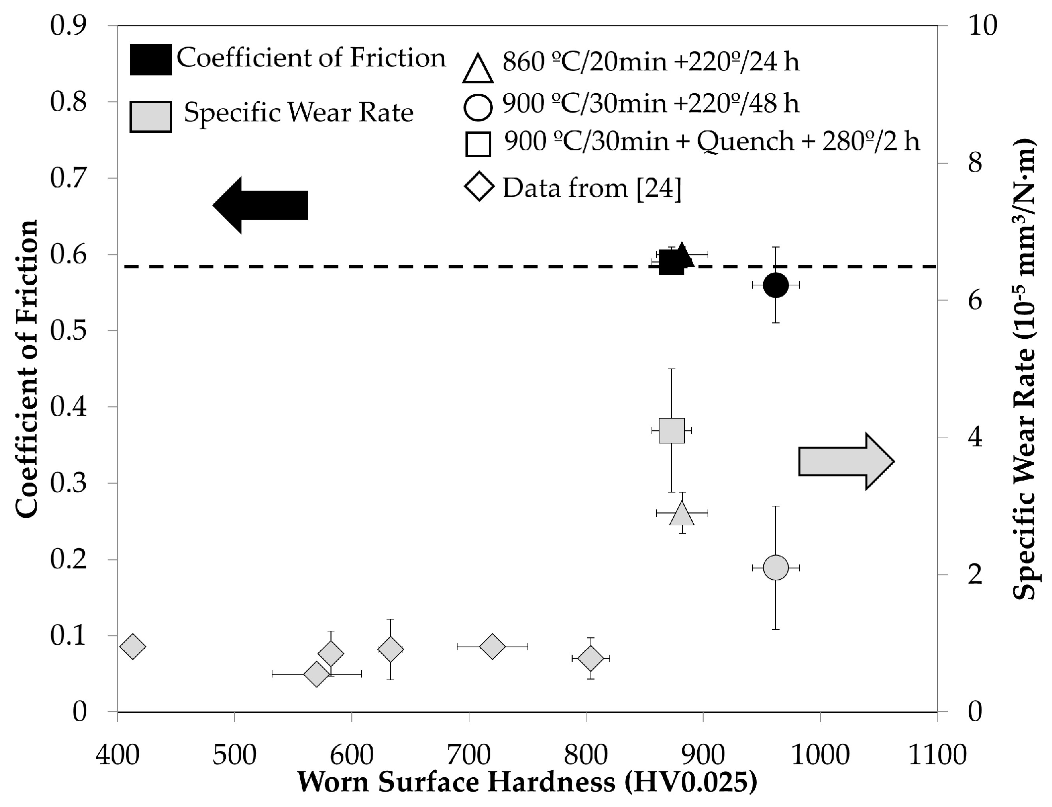
Figure 6.
Coefficient of friction (black points) and specific wear rate (grey points) as a function of the worn surface hardness of bainitic structures formed at 220 °C after austenitization at 860 °C for 20 min (circles) and 900 °C for 30 min (triangles); martensitic structures formed after austenitization at 900 °C for 30 min, quenching, and tempering at 280 °C for 2 h (squares) in Nanobain bearing steel; and bainitic and tempered martensitic structures obtained in a 1C-2.3Si, as reported elsewhere [
24].
Figure 7.
(a), (b), (c), (d) and (e) secondary scanning electron microscopy (SE-SEM) micrographs and (f) Backscattered scanning electron microscopy (BS-SEM) micrograph of the worn surfaces and wear debris after rolling/sliding wear of the sample transformed to bainite at 220 °C after austenitization at 900 °C for 30 min Red squares represent the EBS analysis areas.
Figure 8.
Contact fatigue performance, evaluated in terms of maximum penetration depth as a function of number of cycles. Nanobain bearing steel transformed to bainite at 220 °C after (a) austenitization at 860 °C for 20 min (b) and 900 °C for 30 min; and to (c) tempered martensite after austenitization at 900 °C for 30 min, quenching, and tempering at 280 °C for 2 h, in comparison to (d) commercial 100Cr6 bainitic steel. For each case, three indentations were done.
Figure 9.
Geometry of the manufactured prototypes.
Figure 10.
Evolution of spalling on a dent generated on a ring with a nano-scale, bainitic structure formed at 220 °C for 24 h: (a) 36 h, (b) 48 h, and (c) 60 h.
Table 1.
Typical specifications for bearing steels.
| Properties | Target Value |
|---|
| Hardness | 650–800 HV |
| Yield Strength | >1600 MPa |
| UTS | >2200 MPa |
| Fracture Toughness | >20 MPa√m |
| Hardenability | Higher than that of 100Cr6 and comparable to that of 100CrMo7 |
Table 2.
Chemical composition of nano-scale bainitic steels, wt.% [
8].
| Steel | C | Si | Mn | Cr | Mo | V | Nb | Co | Al |
|---|
| First Generation | | | | | | | | | |
| Nanobain 1 | 0.79 | 1.59 | 1.94 | 1.33 | 0.30 | 0.11 | - | - | - |
| Nanobain 2 | 0.83 | 1.57 | 1.98 | 1.02 | 0.24 | - | - | 1.54 | - |
| Nanobain 3 | 0.78 | 1.49 | 1.95 | 0.97 | 0.24 | - | - | 1.60 | 0.99 |
| Second Generation | | | | | | | | | |
| Nanobain 4 | 0.99 | 1.58 | 0.76 | 0.45 | - | - | - | - | - |
| Nanobain 5 | 1.00 | 1.53 | 0.75 | 0.51 | - | - | 0.02 | - | - |
| Nanobain 6 | 1.01 | 1.51 | 0.82 | 0.46 | 0.10 | - | - | - | - |
| Nanobain 7 | 0.98 | 2.90 | 0.77 | 0.45 | - | - | - | - | - |
| Nanobain 8 | 0.88 | 1.54 | 0.69 | 0.50 | - | - | - | - | - |
| Nanobain 9 | 0.67 | 1.60 | 1.25 | 1.50 | - | - | - | - | - |
| Nanobain 10 | 0.61 | 1.45 | 0.76 | 2.42 | - | - | - | - | - |
| Nanobain 11 | 0.64 | 1.60 | 1.27 | 1.50 | - | - | 0.03 | - | - |
| Nanobain 12 | 0.58 | 1.63 | 1.29 | 1.43 | 0.10 | - | - | - | - |
| Nanobain bearing steel | 0.98 | 1.27 | 0.99 | 1.36 | 0.02 | - | - | - | 0.04 |
Table 3.
Austenitising and austempering conditions investigated, and the corresponding transformation times, hardness values, and retained austenite contents of the resulting microstructures, as determined by dilatometry.
| Austenitising | Austempering | Transformation Time (h) | Hardness (HV30) | Austenite Content (%) |
|---|
| 840 °C/30 min | 220 °C/16 h | 9.3 | 714 | 8.3 |
| 860 °C/20 min | 220 °C/24 h | 8.8 | 710 | 10.6 |
| | 250 °C/15 h | 4.3 | 650 | 11.5 |
| | 270 °C/6 h | 2.3 | 617 | 12.5 |
| 900 °C/30 min | 220 °C/48 h | 17.9 | 672 | 16.1 |
Table 4.
Heat-treatments performed in Nanobain bearing steel. TQ is the quench temperature, and Tiso and tiso are the isothermal heat-treatment temperature and time, respectively.
| Sample | Austenitising | TQ, °C | Tiso, °C | tiso, h |
|---|
| B-230 | 900 °C/30 min | 230 | 230 | 35 |
| B-280 | 900 °C/30 min | 280 | 280 | 15 |
| B-350 | 900 °C/30 min | 350 | 350 | 4.5 |
| QP-230 | 900 °C/30 min | 70 | 230 | 100 |
| QP-280 | 900 °C/30 min | 70 | 280 | 3.6 |
| QP-350 | 900 °C/30 min | 70 | 350 | 2.0 |
| QT-230 | 900 °C/30 min | RT | 230 | 80 |
| QT-280 | 900 °C/30 min | RT | 280 | 2.0 |
| QT-350 | 900 °C/30 min | RT | 350 | 2.0 |
Table 5.
Heat treatments conditions selected for industrial investigations and preliminary mechanical properties.
| Austenitising | Treatment | Hardness (HV30) | Austenite Content (%) | YS (MPa) | UTS (MPa) | Charpy (J/cm²) | |
|---|
| 860 °C/20 min | Austemp. at 200 °C/58 h | 740 | 10.1 | - | - | 6.2 ± 0.3 | - |
| | Austemp. at 220 °C/24 h | 710 | 10.6 | 1979 ± 21 | 2292 ± 29 | 5.4 ± 0.9 | - |
| | Austemp. at 250 °C/15 h | 650 | 11.5 | - | - | - | 25 ± 0.05 |
| | Q&T at 230 °C/2 h | 750 | 10.2 | - | - | 3.4 ± 0.2 | |
| 900 °C/30 min | Austemp. at 220 °C/48 h | 672 | 16.1 | - | - | - | - |
| | Q&T at 280 °C/2 h | 738 | 15.4 | 1824 ± 9 | 2191 ± 23 | - | - |
Table 6.
Monotonic and cyclic loading conditions.
| Monotonic loading conditions: | Rockwell diamond tip of 10 µm in radius
Maximum load of 2 N
Loading rate of 4 N/min
Unloading rate of 4 N/min |
| Cyclic loading conditions: | Rockwell diamond tip of 10 µm in radius
Maximum load of 2 N
Minimum load of 0.02 N
400 cycles
Loading rate of 4 N/min
Unloading rate of 4 N/min |
Table 7.
Rolling contact fatigue (RCF) testing conditions for industrial components.
| Magnitudes | Testing Values |
|---|
| Axial load | 330 daN |
| Radial load | 660 daN |
| Rotation speed | 2250 rev/min |
| Hertz pressure | 2.8 GPa |
| Fit on shaft | M5 |
Table 8.
Lifetime L10 calculations performed for components tested in artificial pollution tests.
| Treatment | No. of Bearings | Spalling Number | L10 in Hours-90% Confidence Limit | ß Slope |
|---|
| Lower Limit | L10 | Higher Limit |
|---|
| Austemp. at 200 °C/58 h | 14 | 8 | 75.4 | 111.7 | 165.5 | 2.9 |
| Austemp. at 220 °C/24 h | 16 | 8 | 55.5 | 104.1 | 195.1 | 1.67 |
| Q&T at 230 °C/2 h | 16 | 8 | 137.1 | 233 | 396 | 2.01 |
© 2019 by the authors. Licensee MDPI, Basel, Switzerland. This article is an open access article distributed under the terms and conditions of the Creative Commons Attribution (CC BY) license (http://creativecommons.org/licenses/by/4.0/).

 ,
, 


