Article

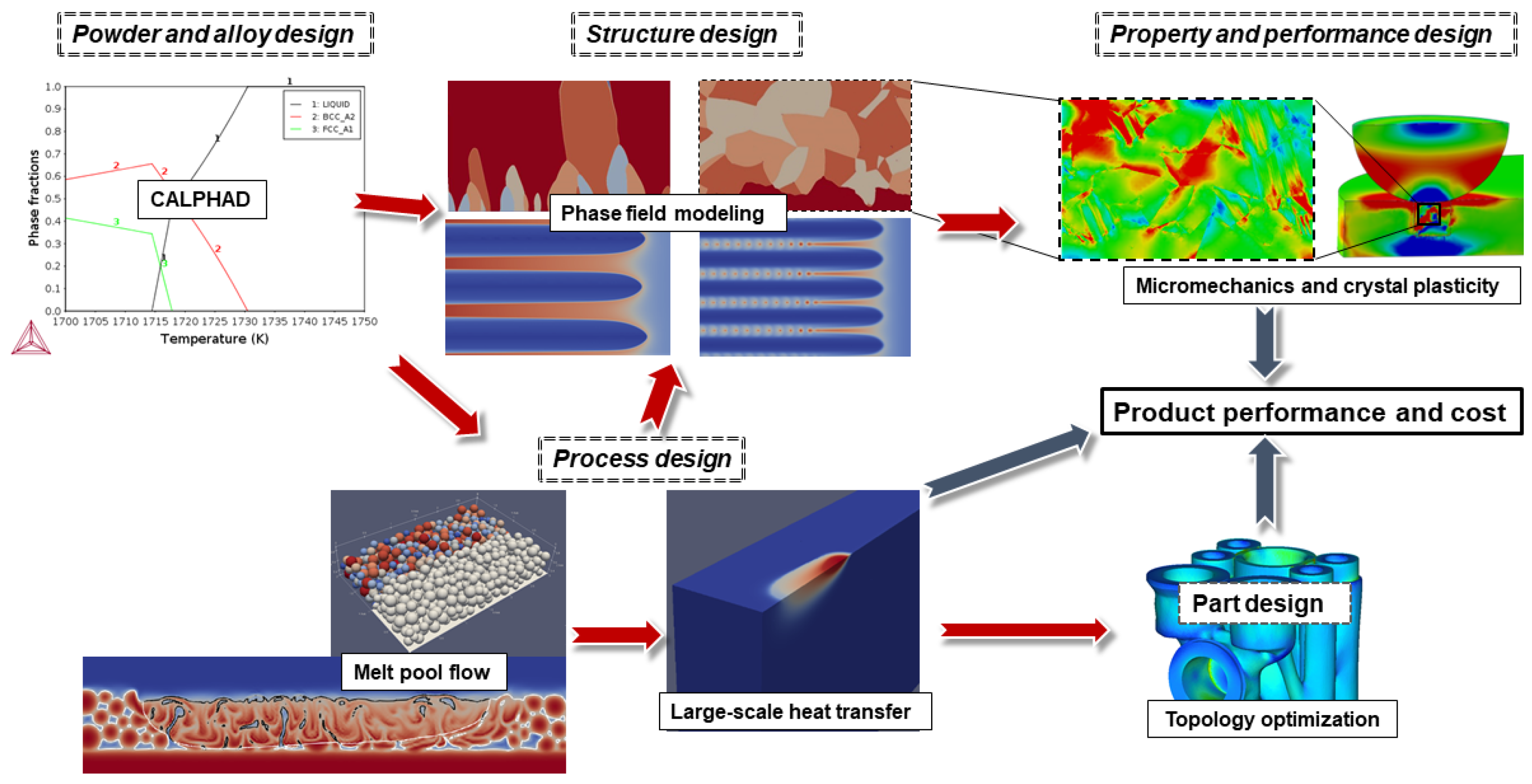
Process-Structure-Properties-Performance Modeling for Selective Laser Melting

1
Multiscale Materials Modeling Group, VTT Technical Research Centre of Finland Ltd., 02150 Espoo, Finland
2
Department of Physics and Centre for the Physics of Materials, McGill University, Montreal, QC H3C-1K3, Canada
3
Department of Computer Science, Aalto University, 02150 Espoo, Finland
*
Author to whom correspondence should be addressed.
Metals 2019, 9(11), 1138; https://doi.org/10.3390/met9111138
Submission received: 29 September 2019 / Revised: 15 October 2019 / Accepted: 17 October 2019 / Published: 24 October 2019
(This article belongs to the Special Issue Advanced Simulation Technologies of Metallurgical Processing)

Abstract

:
Selective laser melting (SLM) is a promising manufacturing technique where the part design, from performance and properties process control and alloying, can be accelerated with integrated computational materials engineering (ICME). This paper demonstrates a process-structure-properties-performance modeling framework for SLM. For powder-bed scale melt pool modeling, we present a diffuse-interface multiphase computational fluid dynamics model which couples Navier–Stokes, Cahn–Hilliard, and heat-transfer equations. A computationally efficient large-scale heat-transfer model is used to describe the temperature evolution in larger volumes. Phase field modeling is used to demonstrate how epitaxial growth of Ti-6-4 can be interrupted with inoculants to obtain an equiaxed polycrystalline structure. These structures are enriched with a synthetic lath martensite substructure, and their micromechanical response are investigated with a crystal plasticity model. The fatigue performance of these structures are analyzed, with spherical porelike defects and high-aspect-ratio cracklike defects incorporated, and a cycle-amplitude fatigue graph is produced to quantify the fatigue behavior of the structures. The simulated fatigue life presents trends consistent with the literature in terms of high cycle and low cycle fatigue, and the role of defects in dominating the respective performance of the produced SLM structures. The proposed ICME workflow emphasizes the possibilities arising from the vast design space exploitable with respect to manufacturing systems, powders, respective alloy chemistries, and microstructures. By digitalizing the whole workflow and enabling a thorough and detailed virtual evaluation of the causal relationships, the promise of product-targeted materials and solutions for metal additive manufacturing becomes closer to practical engineering application.

1. Introduction

Selective laser melting (SLM) is a novel technique to produce metallic parts with complex and easily customizable geometries with limited subtractive steps such as machining, typically for higher-end applications in aerospace, automotive, and biomedical industries [1]. In SLM, a metal powder layer is spread on a substrate, after which a laser melts the layer at preselected regions. New layers are repeatedly added and selectively melted, until the final part has formed. SLM is a relatively new manufacturing technology, and as a result, the current alloy compositions might need to be modified to maintain similar properties achieved with traditional techniques such as casting or wrought parts. Compared to traditional manufacturing methods, due to local powder fusion in rapid solidification conditions and solid-state heat cycling, the resulting microstructures present unique features such as metastable phases, smaller scale microsegregation, formation of unexpected secondary phases, spherical or high-aspect-ratio pores, oxide inclusions, microstructural residual stresses, melt pool boundaries, grains with complex morphology, and strong texture.
The aforementioned structural features in SLM lead to properties and performance that are unexpected [1]. For example, stainless steel 316L can achieve remarkably high hardness and ductility [2] but has a susceptibility to pitting corrosion [3]; Inconel 625 nickel superalloy contains detrimental intermetallic and carbide phases [4]; Ti-6-4 tends to produce hard needlelike α martensite which leads to high hardness but low ductility; tool steels are extremely difficult to fabricate with SLM due to their complex metallurgy, including a tendency to form brittle martensite and high volume fractions of carbides, which lead to high residual stresses due to high thermal gradients and solid-state transformations, resulting in an unacceptable amount of cracking [1].
Considering applications requiring, e.g., high tensile strength or fatigue performance, it is important to understand the formation and mechanical effects of defects such as high-aspect-ratio lack-of-fusion pores or spherical trapped gas pores [5]. SLM potentially allows for direct control of local material properties in the manufactured part, based on a thorough understanding between the feedstock material, controllable process parameters, and the resulting local microstructural features [6,7]. By further mapping the structure to the properties and performance, the part design can be intelligently guided with process-structure-properties-performance (PSPP) modeling chain, which spares time and money compared to trial-and-error type design, which is the core idea of integrated computational materials engineering (ICME).
Significant progress has been made in developing submodels for the PSPP chain [8]. Physics-based causal computer modeling can accelerate the process design [8], for example, to improve the density of SLM tool steels [9]. Khairallah et al. presented a melt pool model with multiphase fluid flow, heat transfer, and ray-tracing that describes process-induced spattering, pore formation, and denudation zones [10]. Keller et al. presented a process-structure modeling approach for SLM of Inconel 625 [4], where a large-scale heat-transfer model was used to estimate thermal gradients and cooling rates, which were used to drive directional solidification via phase field method. Francois et al. reviewed the existing methods for simulating polycrystalline solidification structure formation [8]. Yan et al. presented a process-structure-properties modeling framework for additively manufactured materials, with an emphasis on data mining [7]. Microstructure-associated problems have been addressed by Holmberg et al. [11] and Laukkanen et al. [12] who introduced methods to address complex and realistic material microstructures. To address anisotropic-deformation-associated behavior at the scale of the material microstructure, Lindroos et al. [13,14] utilized crystal plasticity to capture plastic slip behavior and extended the PSPP analysis to consider performance critical mechanisms in [15], particularly, the micromechanics of fatigue. Even still, holistic PSPP modeling frameworks are missing, especially with proper sequential coupling between the models in the framework. Further subject areas are uncertainty quantification and model validation. Many of the modeling approaches themselves need to be pushed from qualitative to quantitative, which necessitates extensive joint further work between experiments and materials modeling.
This paper presents a process-structure-properties-performance modeling framework for selective laser melting, illustrated in Figure 1, using results for SLM of Ti-6-4 alloy to demonstrate most of the methods. We start from a diffuse-interface melt pool model, followed by a computationally efficient large-scale heat conduction model. The local solidification microstructure evolution is described with a phase field model. Finally, the micromechanical stress-strain response and fatigue life are simulated with the crystal plasticity model for Ti-6-4 alloy with a martensitic substructure, and different types of defects. The work introduces a basis for ICME-like analyses for metal additive manufacturing (AM) and workflows where the different models and approaches can interact.

2. Methods

2.1. Diffuse-Interface Melt Pool Modeling

The melt pool model can be used to accurately predict the melt pool geometry, gas pore trapping, calibrate the part scale heat conduction model, and calculate thermal gradients and cooling rates for the rapid solidification phase field model.
The model includes the following phenomena: heat-transfer, melt and gas flow, buoyancy, melt-gas interface dynamics including Marangoni effect, and solidification. This melt pool dynamics is described with a fully coupled system of equations: energy equation for temperature evolution, Navier–Stokes equations for fluid flow, Cahn–Hilliard equation for metal-gas phase tracking.
The two-phase flow with different densities and viscosity is modeled by the diffuse-interface model proposed in [16]:
t ρ v + ρ v + J · v · 2 η D v + p ρ g f = 0 ,
· v = 0 ,
ϕ m g t + v · ϕ m g · m μ = 0 ,
δ F δ ϕ m g μ = 0 ,
with suitable initial and boundary conditions.
Equations (1) and (2) are the Navier-Stokes equations, and Equations (3) and (4) are the Cahn-Hilliard equation split into two equations, where J = ρ ϕ m g m μ is the correction flux that is zero in case of equal phase densities; ϕ m g denotes the metal-gas phase field, μ is the chemical potential; v is the volume averaged velocity; p is the pressure; ρ = ρ ( ϕ m g ) = 1 2 ( ( ρ m ρ g ) ϕ + ( ρ g + ρ m ) ) is the mean density, where ρ g is the gas or vapor density; and ρ m is the density of the condensed solid or liquid metal. η is the mean viscosity defined similarly to the mean density. The mobility is denoted by m = m ( ϕ m g ) . The gravitational force is denoted by g, and f gathers other possible external forces, like stress due to surface tension. D v = 1 2 ( v + ( v ) T ) is the symmetrized gradient (the rate of deformation tensor).
Let the scaled surface tension be denoted by σ ^ and the interfacial width be proportional to ϵ . F : = F ( ϕ m g , ϕ m g , ϕ s l , ϕ s l , T ) represents the global free energy functional, where subscripts m g and s l represent the variables associated with metal-gas and solid-liquid phase functions, respectively. Then, a suitable form of F makes it possible to model systems with multiple phases as
F = σ ^ Ω ϵ m g 2 | ϕ m g | 2 + ϵ m g 1 w ( ϕ m g ) d Ω + Ω ϵ s l 2 | ϕ s l | 2 + ( 1 ϕ ^ m g ) f m e t a l + ϕ ^ m g f g a s d Ω ,
where the free energy density of the metal phase is
f m e t a l ( ϕ s l , T ) = g ( ϕ s l ) + L T m T T m p ( ϕ s l ) ,
and w ( · ) and g ( · ) are suitable double-well functions, p ( · ) is an interpolation function.
Evolution of metal-gas phase function ϕ m g is governed by the Cahn–Hilliard model in Equations (3) and (4). ϕ s l is a phase function, which distinguishes solid and fluid domains. In general, one would need to solve the Allen–Cahn equation to simulate the dynamics of the melt interface. However, we assume the melt interface position to be at steady-state at any instant in time and use an analytical expression for the phase function ϕ s l as a function of temperature T:
ϕ s l ( T ) = 1 2 tanh T T m Δ T + 1 ,
where T m is the melting temperature and Δ T is the temperature range for diffuse-interface. Then, material parameters may depend on ϕ s l , as well as ϕ m g and T.
Modeling solid–liquid phase transition and Marangoni effect requires the temperature field. Therefore, the Navier–Stokes/Cahn–Hilliard system is coupled to a variant of the convective heat-transfer equation, described in Section 2.2.
The Marangoni effect is the convection due to a gradient of the surface tension. The variations in the surface tension are caused by temperature dependence. In order to model the thermal induced Marangoni effect, the temperature-dependent surface tension coefficient σ is approximated by the Eötvös rule and it takes the form of a linear function on the temperature such that
σ ( T ) = σ 0 ( a b T ) ,
where the coefficients σ 0 > 0 , a > 0 , b 0 are assumed to be constants. The constants a and b are related to the capillary and the Marangoni numbers [17].

2.2. Large-Scale Heat-Transfer Modeling

A computationally efficient heat conduction model is simulate temperature distribution in large volume. This model is used to roughly estimate the melt pool geometry and the associated thermal gradients and cooling rates in order to drive alloy phase field simulations, and secondary heat cycles to obtain better solid-state behavior such as back-diffusion, precipitation, and allotropic transformations.
The model interpolates the thermal conductivity and heat capacity between powder and bulk solid phases. Latent heat term is modeled as a Gaussian term. The evolution of temperature T is modeled with the following heat conduction equation:
C p ( T ) T t = · k ( T ) T + L 1 2 π Δ T exp T T m i d Δ T 2 ,
where C p ( T ) is the temperature-dependent heat capacity, k ( T ) is the temperature-dependent heat conductivity, L is the latent heat, Δ T = T l T s is the difference between liquidus and solidus temperatures, and T m i d = ( T l + T s ) / 2 is their average value.
The effect of a powder layer is taken into account simply as the decrease in heat capacity and thermal conductivity. We consider a 20 μ m powder layer, which is assumed to decrease the heat capacity by an amount corresponding to the packing fraction, assumed to be 55%. Thermal conductivity is assumed to decrease to 20% of the bulk value.
The top boundary has a fixed flux boundary condition, which is a sum of heat fluxes from the laser heat source I l a s e r , convective cooling I c o n v e c t i o n from the inert process gas, and radiative cooling I r a d i a t i o n . The laser is assumed to have a Gaussian intensity profile, whose intensity at top boundary Ω t o p is implemented as a boundary condition:
I l a s e r ( x , t ) = η P f π R L 2 exp f x x c e n t e r ( t ) R L 2 , where x Ω t o p ,
η is the gray-body absorptivity, R L is the Gaussian beam width, f is the power intensity factor that describes how focused the intensity is around the beam center [1], and x c e n t e r ( t ) is the time-dependent center of the laser beam. Convection flux is
I c o n v e c t i o n = h c T T a m b i e n t ,
where h c is the effective convective heat-transfer coefficient and T a m b i e n t is the ambient temperature. The radiative cooling is assumed to follow a simple gray-body radiation
I r a d i a t i o n = η σ S B T 4 T a m b i e n t 4 ,
where σ S B is the Stefan–Boltzmann constant. Note that, in Equations (9) and (11), we assume that the metal surface (of powder, liquid, and solid) is a gray body in radiative exchange equilibrium, and thereby that emissivity is equal to absorptivity. Boundaries other than the top surface are assumed to have zero heat flux boundaries. The relevant heat-transfer model parameters are shown in Table 1.

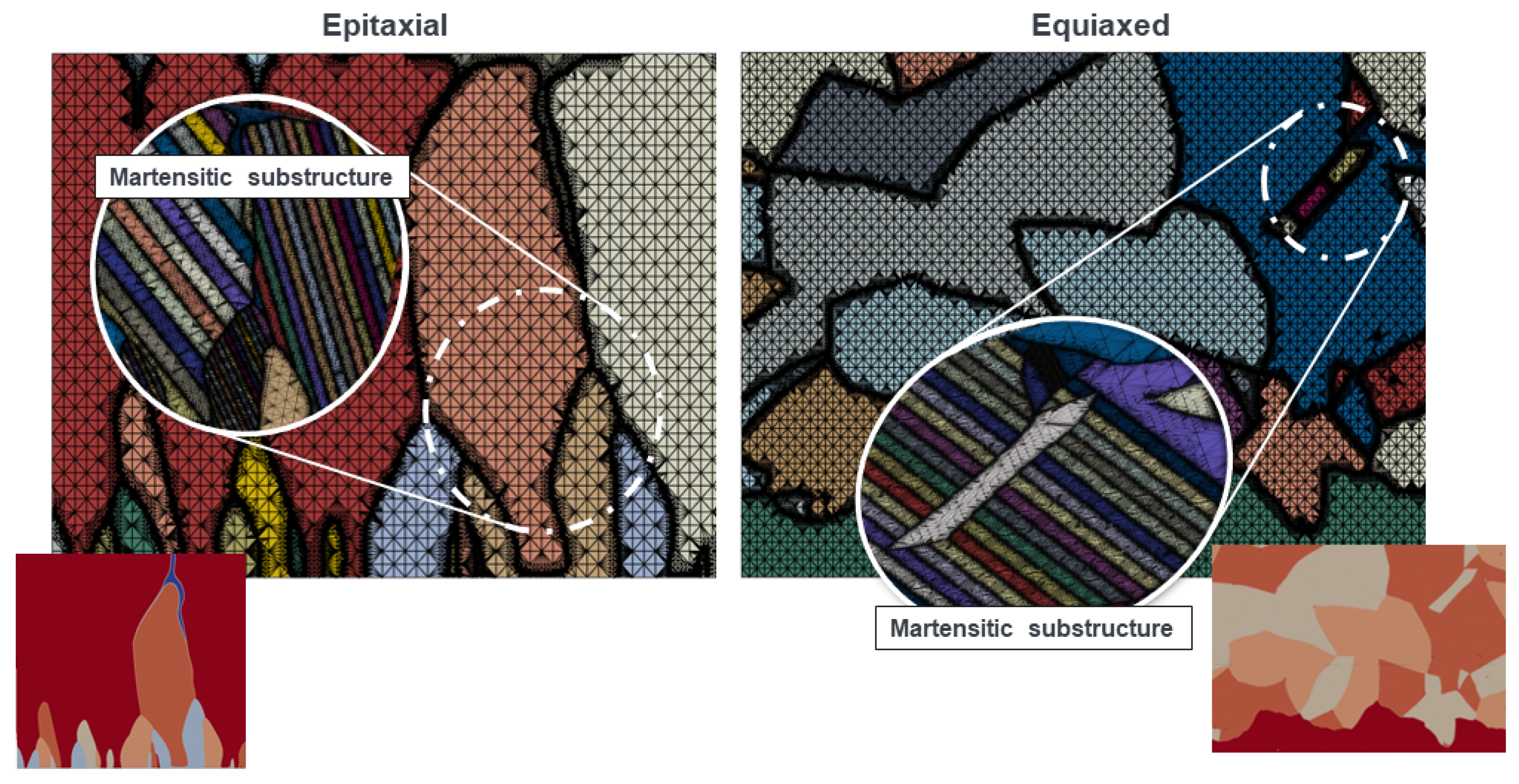
2.3. Rapid Microstructure Solidification Phase Field Modeling

We use phase field method to simulate the rapid solidification of Ti-6-4, where we neglect composition diffusion because the small melting range of Ti-6-4 is assumed to lead to negligible microsegregation and constitutional undercooling effects. Therefore, we model the solidification with the thermal phase field model of [18]. Heterogeneous nucleation from inoculants is modeled by incorporating thermal noise to the order parameter whose strength is determined from fluctuation-dissipation theorem. Inoculants are described with a wall field introduced in [19].
Assuming in total N unique crystalline orientations α , the evolution of order parameters ϕ α are governed by
τ ϕ α t = · W 2 ϕ α + W α | ϕ α | 2 k x , y , z W α ( ϕ α / k ) e ^ k + ϕ α ϕ α 3 + ω ϕ α α α ϕ α 2 λ U g ( ϕ α ) + τ η α + | ϕ W | W 2 ϕ α · ϕ W | ϕ W | 6 σ S L h α = 1 , , N ,
where τ is the interface attachment time scale, W α = W α ( n α ) is the anisotropic interface width of orientation α and n α = ϕ α / | ϕ α | is the interface normal, ω sets the strength of repulsive interaction between order parameters of different crystalline orientations [20], λ is the so-called coupling constant, η α is the thermal noise term discussed below, ϕ W is a static “wall field” introduced to induce heterogeneous nucleation according to [19], σ S L is the solid–liquid interface energy, h is a parameter used to set control the contact angle, and N is the total number of crystalline orientations considered.
The noise term η α in Equation (12) is a random variable which is uncorrelated in space and time, and follows fluctuation-dissipation theorem:
< η α , η α > = 2 1 τ k B T δ ( r r ) δ ( t t ) .
The evolution of dimensionless temperature U is
U t = D 2 U + 1 2 α ϕ α t ,
where D is the heat diffusion coefficient, assumed to be constant.
Matched interface asymptotics from [18] is used to relate physical material parameters (thermal capillary length d o and kinetic coefficient β ) to phase field parameters (W, τ , and λ ) as follows:
d o ( n α ) = a 1 W ( n α ) λ ,
β ( n α ) = a 1 τ ( n α ) λ W ( n α ) a 1 a 2 W ( n α ) D ,
where a 1 0.8839 and a 2 0.6867 are asymptotic constants. We assume a negligible capillary anisotropy due to rapid solidification conditions [21]. The kinetic coefficient β ( n ) is assumed to have weak cubic lattice anisotropy:
β ( n α ) / β 0 = 1 + 3 ϵ k 4 ϵ k n x , α 4 + n y , α 4 + n z , α 4 ,
where β 0 is the magnitude of the anisotropic kinetic coefficient β ( n α ) , and ϵ k is its anisotropy strength. The relevant phase field model parameters are shown in Table 2.
In this phase field model, we only consider the primary solidification (liquid-to- β ), and neglect the martensitic transformations. However, the lamellar martensitic structure is synthesized into the polycrystalline structure given by the phase field model, and the micromechanical response of this martensitic structure is subsequently analyzed with a crystal plasticity model.

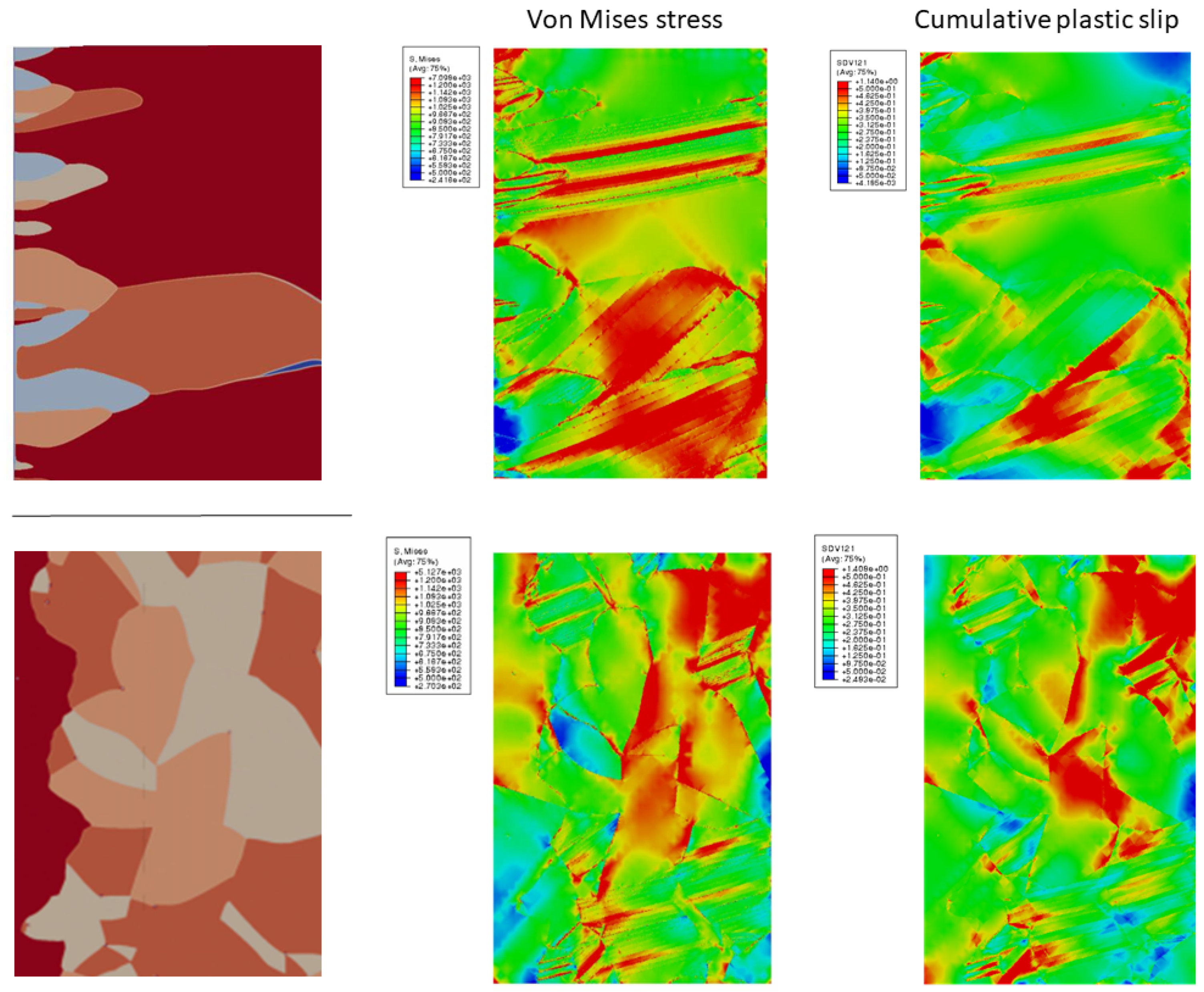
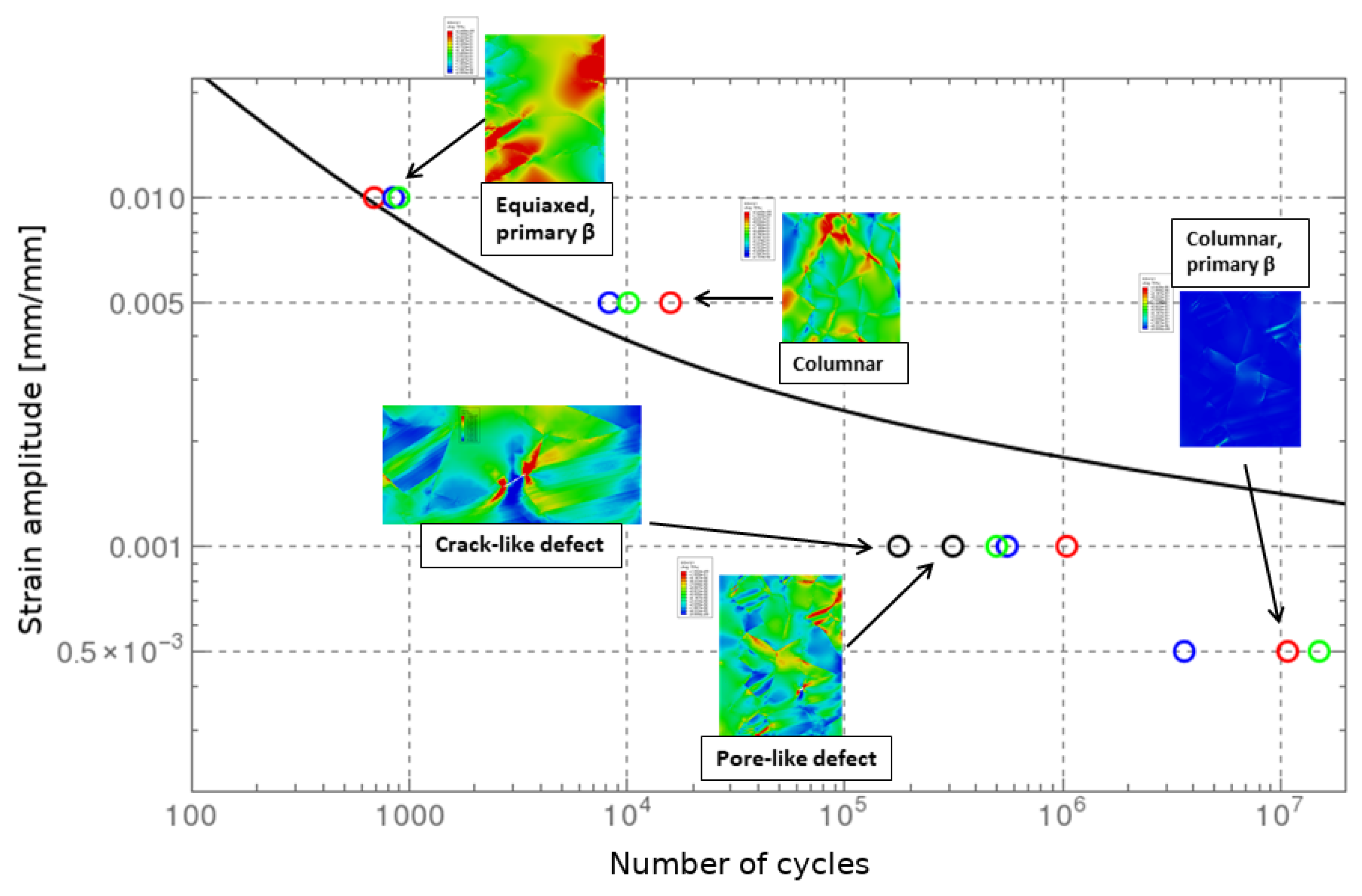
2.4. Mechanical Response with a Micromechanical Crystal Plasticity Model

The micromechanical approach relies on crystal plasticity modeling to establish the stress state as well as evolution of slip-system-specific plastic slip during cyclic loading. A multiplicative decomposition of elastic and plastic displacement gradients is used for large strains. The resolved shear stress is utilized as the criterion for plastic flow. Classical crystal plasticity framework is utilized in current work, i.e., no higher order terms inducing scale dependencies are included.
The microstructure is modeled as a BCC β -phase or martensitic HCP α -phase. The methodology enables the modeling of α + β -containing alloys or α and retained β -phase ones, but in current work, the focus is on fully α consisting microstructures, especially the martensitic α . Thus, for example, slip transmission or more complex deformation mechanisms and their interactions arising at phase interfaces are not investigated nor included. Few cases are evaluated with primary solidified β grain dominated microstructures, for reference, the α -phase, especially with respect to its acicular morphology, is of interest particularly since it is a probable outcome considering the rapid solidification conditions persistent in metal AM. With respect to the α -phase, the HCP is modeled considering the prismatic ( { 10 1 ¯ 0 } , 11 2 ¯ 0 systems, three slip systems), basal ( { 0001 } , 11 2 ¯ 0 systems, three slip systems), and pyramidal ( { 10 1 ¯ 1 } , 11 2 ¯ 3 } , 12 slip systems) slip systems. For the β -phase, 12 slip systems of type ( { 110 } , 111 ) were considered, the rate of plastic slip and evolution equations for the hardening terms are described utilizing similar expressions, as presented in more detail below.
In order to capture mixed-hardening response suited for assessment of cyclic loading, both isotropic and kinematic contributions are incorporated, the model is adapted from work performed in [23]. Resolved shear stress for slip system s is obtained classically from
τ s = σ : 1 2 n s m s + m s n s ,
where σ is the Cauchy true tensor, m is the vector parallel to the slip direction, and ni s the vector normal to the slip plane. The slip rate for slip system s is evaluated according to a phenomenological relation:
γ ˙ s = γ ˙ c u m s s i g n τ s x s = | τ s x s | r s K n s i g n τ s x s ,
where K and n are material parameters of the constitutive formulation associated with viscous response, γ c u m is the cumulative plastic slip, and the isotropic and kinematic hardening contributions are provided by
r s = R 0 + Q r h r s 1 exp b γ c u m r ,
where R 0 , Q, b, and h r s are material dependent coefficients and
x s = c α s = c γ ˙ s d α s γ ˙ c u m s ,
where c and d are material related coefficients. The calibration of the various coefficients is based on numerical homogenization, following the practices presented in [13,15]. For the braces, a convention is adopted where x = m a x ( x , 0 ) .
Since the focus of current work is in establishing crystal plasticity-based micromechanical worklowsfor Ti-6-4 rather than quantitatively assessing specific use cases, literature data is utilized in establishing model parameterization. Different slip family critical resolved shear stresses are obtained from [24], and the viscoplastic parameterization from [23], which is adapted to match additively manufactured Ti-6-4 uniaxial tensile loading properties, as presented in [25] (by adjusting the hardening parameters to yield a comparable tensile response). Texture data is adapted from PF simulations and, for the interaction coefficients, only diagonal initial hardening modulus is used, neglecting latent hardening. Microstructural model generation, operations on the primary solidified β structure, and meshing of the resulting geometry are performed by utilizing the toolset presented in more detail in [11,26].
The micromechanical assessment of fatigue is performed utilizing the so called Fatigue Indicator Parameters (FIPs). To that effect, we utilize the Fatemi–Socie (FS) criterion, as presented in [27], and applied it to the high-cycle fatigue (HCF) regime, for example, in [28]. The FS criterion one of the most utilized FIP parameters, commonly defined as:
Δ γ m a x p 2 1 + K σ n m a x σ y = γ ¯ f 2 N c c ,
where Δ γ m a x p is the change in maximum cyclic plastic strain over a finite volume (in current work interpreted as a local maximum greater than adjacent field mean value) and σ n m a x is the stress normal to affiliated plane. The remainder of the parameters follow a Coffin–Manson type of a representation for strain life, σ y is the cyclic yield strength and K is a parameter weighing the coupling between normal stress and cyclic plastic slip (K in current is as is common considered to have a value of unity). γ ¯ f and c are the Coffin–Manson parameters, N c are the respective cycles to fatigue failure. The parameter has been applied in different contexts commonly over cumulative plastic slip, but also over specific slip systems respective behavior. In current work the parameter is evaluated with respect to cumulative plastic slip. The fatigue damage evolution law parameters are obtained from [29], where cyclic properties and fatigue response of additively manufactured Ti-6-4 are investigated experimentally.
With respect to the fatigue analysis microstructures, the different equiaxed and columnar α and β -phase-dominated microstructures are loaded cyclically under R = 0 loading ratio in strain amplitude control to investigate the low-cycle fatigue (LCF)- and HCF-response of the respective microstructures. Additionally, since in the context of AM defects and their influence to fatigue performance are of particular interest, postulated microstructure scale defects are introduced explicitly to the microstructures and the respective effect to fatigue life prediction assessed. This consists of porelike and cracklike defects with sizes comparable to the microstructural morphological features with respect to the acicular α laths.

3. Results

3.1. Diffuse-Interface Melt Pool Dynamics

The melt pool dynamics model is implemented using FEniCS Project library [30]. The system of equations is discretized in space using the mixed finite element method, and in time using an implicit method. Stable time discretizations are discussed, for example, in [31,32]. The whole domain size was 3 × 1 mm 2 , and we used triangular elements refined around the powder bed region, where the smallest element size was 6.25 μ mx. The mesh consisted of 147,120 triangles in total. Quadratic elements were used for velocity vector and linear elements for pressure, temperature, phase field, and chemical potential; this results in 883,910 degrees of freedom (DOFs). The resulting nonlinear system is solved using PETSc’s SNES solver [33,34] and Newton’s method with line search. Additionally, we rely on FEniCS for differentiating the nonlinear residual functional to obtain the Jacobian. At each Newton iteration, the linear system is solved using MUMPS [35].
The powder bed was generated by first generating a fixed number of powder particles following a log-normal size distribution, after which the particles were iteratively packed to fill the assigned powder layer thickness.
An example of 2D melt pool dynamics is shown in Figure 2, where the voids between the powder particles coalesce into bubbles due to surface tension. These bubbles can then freeze into the structure, depending on how rapidly the solidification front advances. In the future, we will carefully consider associated model parameters, such as interface penalty term and the double well-thickness, and extend the diffuse-interface model into three dimensions.

3.2. Large-Scale Heat Transfer

The large-scale heat-transfer model implemented in MOOSE framework [36]. The mesh consists of first-order hexahedral lagrangian elements with adaptive mesh refinement, which are set to resolve solid–liquid boundary region. On highest refinement level, the element size is 9 μ m. We use a two-step backward differentation formula (BDF2) for time integration, with adaptive time stepping targeted to maintain six nonlinear iterations per time step. The system of equations uses Single Matrix Preconditioning (SMP), which is solved with Newton’s method.
The resulting temperature distribution in a single line scan is shown in Figure 3 (top left). The model gives an estimate of the overall melt pool geometry (top right). The model can also be used to estimate the local thermal conditions that drive the solidification—the thermal gradients are estimated along certain directions around the trailing edge of the melt pool (bottom-left). In addition, thermal cycles can be estimated in different scanning patterns: Figure 3 (bottom-right) shows the temperature distribution in a zig-zag scan pattern.
Regarding the large-scale heat-transfer model, we believe that, specifically, the following model parameters are both hard to estimate from literature or theory and affect the heat transfer significantly: gray-body absorptivity η and powder conductivity fraction f c o n d p o w d e r . This model assumes that convective heat transfer in the melt pool is negligible. In the future, we plan to coarse-grain convection effects from the melt pool level model of Section 3.1 into this simple and efficient heat conduction model for more realistic large-scale heat-transfer modeling.

3.3. Rapid Solidification Microstructures

The phase field simulations use the finite difference method with explicit Euler forward time stepping, with the time step size set to 0.8 of the linear stability limit for the heat diffusion equation. The mesh was adaptively refined to capture gradients of order parameter and dimensionless temperature with the software platform introduced in [37]. The used phase field model parameters are shown in Table 2.
We perform polycrystalline Ti-6-4 solidification simulations under a constant initial dimensionless undercooling corresponding to Δ = 0.5 . Figure 4 (left column) shows the competitive growth of nuclei initiated at the bottom of the undercooled melt pool; dark red corresponds to the grain orientation with fastest growth direction closest to the vertical axis, and thereby, it eventually dominates the solidification, leading to an epitaxial polycrystalline structure. The right column of Figure 4 shows how the epitaxial growth is interrupted with randomly placed inoculants in the melt pool; the bottom of the melt pool is initialized with a number of epitaxial fast-growing grains. The inoculants are large enough to nucleate multiple grains of different orientations simultaneously, leading to several high-angle triple junctions. The heterogeneously nucleated grains grow rapidly and radially, giving rise to straight grain boundaries. In contrast, the inoculant-free system (Figure 4, left) has smoother grain boundaries due to the gradual spreading of the fast-growing (dark red) orientation.
Note that, in this simulation, the constant initial undercooling leads to rapid nucleation from all inoculants added to the melt pool. For more quantitative results, we are extending the analysis to a more realistic temperature distribution, coupled to the melt pool model of Section 3.1 and the large-scale heat-transfer model of Section 3.2.
The repulsive grain–grain term in Equation (12), whose strength is determined by interaction parameter Ω , gives qualitatively the right interaction between grains, but the solid–solid interface energy cannot be directly controlled with this approach. We are extending this approach in the future to a more quantitative grain–grain repulsion.

3.4. Micromechanical Properties and Performance Modeling

The phase-field-simulated epitaxial and equiaxed Ti-6-4 polycrystalline structures are used as direct input microstructures to the crystal plasticity modeling of monotonic stress–strain response as well as micromechanical fatigue performance modeling. The polycrystalline structure is assumed to be completely transformed to a simplified description of lathlikemartensite, as shown in Figure 5.
First, a simple tensile loading was performed for these structures, as shown in Figure 6. The equiaxed structure results in a smoother distribution of stresses and strains, whereas the epitaxial structure shows anisotropic stress and strain peaks. In addition, the equiaxed α -dominated structures in general consist of a larger number of misoriented interfaces, which, in the crystal plasticity modeling, manifests itself as increased hardening and greater strength of the resulting microstructure.
Results for the cyclic fatigue loading of these structures are shown in Figure 7. The upper row shows the cumulative plastic slip at different strain amplitudes, for a constant number of loading cycles computed such that a stabilized condition has been obtained. The bottom row introduces two different postulated defect types at a high-angle grain boundary (HAGB): a spherical porelike defect due to excessive laser key-holing, and a high-aspect-ratio cracklike defect due to solidification cracking or incomplete powder melting. The fatigue failure of these structures was estimated by utilizing the FS FIP to evaluate their significance with respect to cycles to fatigue failure.
By considering different amplitudes with different types of defects and the micromechanical measures regarding when they are expected to lead to the nucleation of a macroscale crack identifiable as structural failure (or short fatigue crack nucleation which can already be considered as descriptive), these cyclic loading simulations can be used to generate cycles to failure vs. amplitude fatigue graphs, as shown in Figure 8. For high-strain amplitudes, the nominally-similar different defect-free microstructures show a very similar behavior and break down at similar cycle counts, although the differences are easily several tens of percents. As the amplitude is decreased, there is more scatter in the number of cycles to fatigue failure for the considered microstructures. The introduction of microstructural defects influences the predicted outcome significantly. The simulations show that, compared to spherical pores, high-aspect ratio cracklike defects have a poorer fatigue performance, which is consistent with the literature [1]. Overall, the detrimental effect to fatigue performance of metal AM microstructures is reproduced, and the defects that have been introduced could act as nuclei for, for example, HCF failure. This adds to the confidence that the proposed analysis approaches are beneficial in assessing the micromechanical performance and further developing fatigue-resistant metal AM solutions.

4. Discussion

We presented a modeling framework to investigate the process-structure-properties performance chain for selective laser melting (SLM), where the presented models can be readily coupled in a sequential manner.
The diffuse-interface melt pool model can be used to assess the feasibility of process parameters—primarily, scanning speed, laser power, beam intensity intensity profile, and layer thickness. It gives a high-fidelity estimate of the temperature distribution around the melt pool, which can be used to parameterize a larger-scale heat conduction model, or to drive solidification on a smaller scale via phase field method, or polycrystalline structure formation via cellular automaton or kinetic Monte Carlo type models.
In particular, the model can predict the formation of trapped gas pores, overall melt pool instability due to balling or spattering, and irregularity of the solidified-free surface. The model gives an accurate description of the heat transfer inside the melt pool, where convection, Marangoni effect, and evaporation are crucial features for accurate description of heat transfer in addition to simple conduction. A realistic ray-tracing model should be implemented, such as one used in [10]. We employed a simple gray-body assumption to describe the laser absorption. In reality, for example, the vapor phase can cause significant deviation from this gray-body behavior. Absorptivity can also have a significant temperature dependence. Using a more complicated laser absorption model would require careful experimental validation.
In the future, the melt pool model requires quantitative parameterization and validation, by using experimental data on temperature distribution around the melt pool, based on in situ temperature measurements via thermocouples or thermal cameras, and estimation of melt pool dimensions based on post mortem microstructure characterization. The model includes multiple parameters, which are difficult to estimate or find in the existing literature. Parameter sensitivity analysis of the model will help in the task of testing robustness of the simulation results for a range of different physical parameters, representing different materials and manufacturing conditions. Large computational cost of the model due to the multiphysics coupling prohibits the use of the model in the design optimization loop. One way to mitigate the cost is to construct the surrogate model. In this context, the calibrated large-scale heat-transfer model can be used for the coarse grained description of costly melt pool diffuse-interface simulation.
The large-scale heat-transfer model can be used for relatively fast estimation of overall temperature distribution and secondary heat cycles using a specific scanning strategy, and to assess the risk of forming lack-of-fusion type defects. This will be useful for assessment of scanning strategies, heat accumulation across layers, formation of residual stresses, and microstructure annealing in secondary heat cycles. Efforts to improve the computational efficiency of these models will be of primary interest, in order to provide realistic overall temperature distribution on a level of a full part. Innately, multiscale and adaptive finite element methods and on-the-fly coarse graining between solvers is expected to play an ever increasing role towards the future, in order to push forward both the increase in computational resolution and simultaneously target the reduction of the computational cost.
The presented rapid solidification phase field model can be used to investigate the formation of polycrystalline microstructures as a function of process conditions, alloying, and, e.g., inoculants. In particular, an accurate description of solid-state transformations, such as α martensite formation, will be of great interest. Quantitative usage of lower scale descriptions, such as phase field crystal type models, will be of great interest to better understand the formation of nonequilibrium structures, and, e.g., dislocation formation.
Finally, the mechanical response of these rapid solidification microstructures can be predicted with a micromechanical crystal plasticity model. In addition, these models can assess the importance of different defect types and morphologies, hard oxide inclusions, or the martensite lath spacing. Among other microstructural heterogeneities, defects become particularly important in considering material failure and structural performance, for example, in high-cycle-fatigue conditions. Close coupling between phase field and crystal plasticity models will become desirable to describe, for example, solid-state transformations or microstructural damage. This can be achieved either through a priori phase field modeling studies for crystal plasticity model parameter calibration, concurrent two-way coupled descriptions, or, as would be preferred, fully coupled models.
The presented physics-based models can be readily coupled sequentially, and they provide a basis for investigating causalities within the composition-process-structure-properties performance chain for SLM. However, via brute force computation, it is impractical to cover the relevant materials engineering design space in terms of an optimal alloy composition and optimal processing parameters, and assess whether the resulting structure produces feasible properties and performance behavior. Taking full advantage of the presented modeling framework, one needs high-throughput [38], in situ experiments, and materials informatics methods [39].
Overall, the simulations lead to vast amounts of data, from which relevant information needs to be extracted. These issues can be tackled with concepts from materials informatics [39], where the idea is to make use of present and emerging methods from data science to analyze and drive the modeling chains.
New physics can be extracted, by either choosing between competing models or by determination of hard-to-measure material properties; for example, anisotropic kinetic coefficient or solute-trapping parameters in a phase field model could be extracted from so-called dynamic transmission electron microscopy (DTEM) experiments [40,41,42,43,44]. Expensive, high-fidelity experiments (or simulations) can be better designed and targeted to give maximal useful information through so-called adaptive learning schemes. Relevant microstructural features can be identified, reduced descriptions of microstructures to generate surrogate models for process-structure or structure-property-performance mapping. Inverse design schemes can be used to turn process-structure-properties performance modeling chain around. The uncertainty and sensitivity of an optimal design can be better assessed.
The presented modeling chain will be used together with high-throughput screening of feasible alloy compositions, quick-and-dirty based on CALPHAD-thermodynamic databases, and completely new compositions can be explored with density functional theory (DFT)-based approaches. This can be complemented with high-throughput experimentation, including rapid combinatorial materials synthesis and characterization schemes [38,45].
Future efforts should include in-depth analyses of each presented model separately, with explicit comparisons to experiments. This includes validation of phase field simulations of rapid solidification via so-called Dynamic TEM (DTEM) experiments [43], and in situ SEM tensile testing and nanoindentations to calibrate the crystal plasticity model for an SLM material.

5. Conclusions

We presented an integrated computational materials engineering framework (ICME), demonstrating the behavior of a diffuse-interfaced melt pool model for detailed powder-bed scale process modeling, complemented by an efficient large-scale heat-transfer model. The process models can be used to estimate the risk of forming different type of defects, temperature distribution in solidification, and solid-state secondary heat cycles. Phase field modeling was used to predict the formation of rapid solidification microstructures for Ti-6-4 alloy in epitaxial and equiaxed growth regimes. These solidification microstructures, with potential defects, were analyzed with respect to their micromechanical response and fatigue performance using a crystal plasticity model. Future work will improve and expand the existing models, develop experimental calibration and validation procedures, and form closer couplings between the presented models.

Author Contributions

Writing, T.P., I.Y., M.L., T.A., A.L., and N.P.; methodology, T.P., I.Y., M.L., A.L., N.P., and T.A.

Funding

This work was supported by the Academy of Finland under HIERARCH project, grant number 318065. NP wishes to acknowledge the National Science and Engineering Research Council of Canada and the Canada Research Chairs for support with this project.

Conflicts of Interest

The authors declare no conflict of interest.

Abbreviations

The following abbreviations are used in this manuscript:
AMAdditive Manufacturing
CPCrystal Plasticity
FIPFatigue Indicator Parameters
SLMSelective Laser Melting
PSPPProcess-structure-properties-performance
ICMEIntegrated Computational Materials Engineering

References

  1. DebRoy, T.; Wei, H.; Zuback, J.; Mukherjee, T.; Elmer, J.; Milewski, J.; Beese, A.M.; Wilson-Heid, A.; De, A.; Zhang, W. Additive manufacturing of metallic components–process, structure and properties. Prog. Mater. Sci. 2018, 92, 112–224. [Google Scholar] [CrossRef]
  2. Qiu, C.; Al Kindi, M.; Aladawi, A.S.; Al Hatmi, I. A comprehensive study on microstructure and tensile behaviour of a selectively laser melted stainless steel. Sci. Rep. 2018, 8, 7785. [Google Scholar] [CrossRef]
  3. Sun, Y.; Moroz, A.; Alrbaey, K. Sliding wear characteristics and corrosion behaviour of selective laser melted 316L stainless steel. J. Mater. Eng. Perform. 2014, 23, 518–526. [Google Scholar] [CrossRef]
  4. Keller, T.; Lindwall, G.; Ghosh, S.; Ma, L.; Lane, B.M.; Zhang, F.; Kattner, U.R.; Lass, E.A.; Heigel, J.C.; Idell, Y.; et al. Application of finite element, phase-field, and CALPHAD-based methods to additive manufacturing of Ni-based superalloys. Acta Mater. 2017, 139, 244–253. [Google Scholar] [CrossRef]
  5. Herzog, D.; Seyda, V.; Wycisk, E.; Emmelmann, C. Additive manufacturing of metals. Acta Mater. 2016, 117, 371–392. [Google Scholar] [CrossRef]
  6. Roehling, T.T.; Wu, S.S.; Khairallah, S.A.; Roehling, J.D.; Soezeri, S.S.; Crumb, M.F.; Matthews, M.J. Modulating laser intensity profile ellipticity for microstructural control during metal additive manufacturing. Acta Mater. 2017, 128, 197–206. [Google Scholar] [CrossRef]
  7. Yan, W.; Lin, S.; Kafka, O.L.; Lian, Y.; Yu, C.; Liu, Z.; Yan, J.; Wolff, S.; Wu, H.; Ndip-Agbor, E.; et al. Data-driven multi-scale multi-physics models to derive process–structure–property relationships for additive manufacturing. Comput. Mech. 2018, 61, 521–541. [Google Scholar] [CrossRef]
  8. Francois, M.M.; Sun, A.; King, W.E.; Henson, N.J.; Tourret, D.; Bronkhorst, C.A.; Carlson, N.N.; Newman, C.K.; Haut, T.S.; Bakosi, J.; et al. Modeling of additive manufacturing processes for metals: Challenges and opportunities. Curr. Opin. Solid State Mater. Sci. 2017, 21, 198–206. [Google Scholar] [CrossRef]
  9. Laakso, P.; Riipinen, T.; Laukkanen, A.; Andersson, T.; Jokinen, A.; Revuelta, A.; Ruusuvuori, K. Optimization and simulation of SLM process for high density H13 tool steel parts. Phys. Procedia 2016, 83, 26–35. [Google Scholar] [CrossRef]
  10. Khairallah, S.A.; Anderson, A.T.; Rubenchik, A.; King, W.E. Laser powder-bed fusion additive manufacturing: Physics of complex melt flow and formation mechanisms of pores, spatter, and denudation zones. Acta Mater. 2016, 108, 36–45. [Google Scholar] [CrossRef] [Green Version]
  11. Holmberg, K.; Laukkanen, A.; Turunen, E.; Laitinen, T. Wear resistance optimisation of composite coatings by computational microstructural modelling. Surf. Coat. Technol. 2014, 247, 1–13. [Google Scholar] [CrossRef]
  12. Laukkanen, A.; Pinomaa, T.; Holmberg, K.; Andersson, T. Effective interface model for design and tailoring of WC–Co microstructures. Powder Metall. 2016, 59, 20–30. [Google Scholar] [CrossRef]
  13. Lindroos, M.; Laukkanen, A.; Cailletaud, G.; Kuokkala, V.T. On the effect of deformation twinning and microstructure to strain hardening of high manganese austenitic steel 3D microstructure aggregates at large strains. Int. J. Solids Struct. 2017, 125, 68–76. [Google Scholar] [CrossRef]
  14. Lindroos, M.; Cailletaud, G.; Laukkanen, A.; Kuokkala, V.T. Crystal plasticity modeling and characterization of the deformation twinning and strain hardening in Hadfield steels. Mater. Sci. Eng. A 2018, 720, 145–159. [Google Scholar] [CrossRef]
  15. Lindroos, M.; Laukkanen, A.; Andersson, T.; Vaara, J.; Mäntylä, A.; Frondelius, T. Micromechanical modeling of short crack nucleation and growth in high cycle fatigue of martensitic microstructures. Comput. Mater. Sci. 2019, 170, 109185. [Google Scholar] [CrossRef]
  16. Abels, H.; Garcke, H.; Grün, G. Thermodynamically Consistent, Frame Indifferent Diffuse Interface Models for Incompressible Two-Phase Flows with Different Densities. Math. Model. Methods Appl. Sci. 2012, 22, 1150013. [Google Scholar] [CrossRef]
  17. Guo, Z.; Lin, P.; Wang, Y. Continuous finite element schemes for a phase field model in two-layer fluid Bénard-Marangoni convection computations. Comput. Phys. Commun. 2014, 185, 63–78. [Google Scholar] [CrossRef]
  18. Karma, A.; Rappel, W.J. Quantitative phase-field modeling of dendritic growth in two and three dimensions. Phys. Rev. E 1998, 57, 4323–4349. [Google Scholar] [CrossRef] [Green Version]
  19. Warren, J.A.; Pusztai, T.; Környei, L.; Gránásy, L. Phase field approach to heterogeneous crystal nucleation in alloys. Phys. Rev. B 2009, 79, 014204. [Google Scholar] [CrossRef]
  20. Ofori-Opoku, N.; Provatas, N. A quantitative multi-phase field model of polycrystalline alloy solidification. Acta Mater. 2010, 58, 2155–2164. [Google Scholar] [CrossRef]
  21. Bragard, J.; Karma, A.; Lee, Y.H.; Plapp, M. Linking phase-field and atomistic simulations to model dendritic solidification in highly undercooled melts. Interface Sci. 2002, 10, 121–136. [Google Scholar] [CrossRef]
  22. Boivineau, M.; Cagran, C.; Doytier, D.; Eyraud, V.; Nadal, M.H.; Wilthan, B.; Pottlacher, G. Thermophysical properties of solid and liquid Ti-6Al-4V (TA6V) alloy. Int. J. Thermophys. 2006, 27, 507–529. [Google Scholar] [CrossRef]
  23. Meric, L.; Poubanne, P.; Cailletaud, G. Single Crystal Modeling for Structural Calculations: Part 1—Model Presentation. J. Eng. Mater. Technol. 1991, 113, 162–170. [Google Scholar] [CrossRef]
  24. Fundenberger, J.; Philippe, M.; Wagner, F.; Esling, C. Modelling and prediction of mechanical properties for materials with hexagonal symmetry (zinc, titanium and zirconium alloys). Acta Mater. 1997, 45, 4041–4055. [Google Scholar] [CrossRef]
  25. Agius, D.; Kourousis, K.I.; Wallbrink, C. A Review of the As-Built SLM Ti-6Al-4V Mechanical Properties towards Achieving Fatigue Resistant Designs. Metals 2018, 8, 75. [Google Scholar] [CrossRef]
  26. Laukkanen, A.; Holmberg, K.; Ronkainen, H.; Stachowiak, G.; Podsiadlo, P.; Wolski, M.; Gee, M.; Gachot, C.; Li, L. Topographical orientation effects on surface stresses influencing on wear in sliding DLC contacts, Part 2: Modelling and simulations. Wear 2017, 388–389, 18–28. [Google Scholar] [CrossRef]
  27. Dabiri, M.; Laukkanen, A.; Bjork, T. Fatigue Microcrack Nucleation Modeling: A Survey of the State of the Art. Int. Rev. Mech. Eng. 2015, 9, 368–376. [Google Scholar] [CrossRef]
  28. Castelluccio, G.; Musinski, W.; McDowell, D. Computational micromechanics of fatigue of microstructures in the HCF–VHCF regimes. Int. J. Fatigue 2016, 93, 387–396. [Google Scholar] [CrossRef]
  29. Benedetti, M.; Cazzolli, M.; Fontanari, V.; Leoni, M. Fatigue limit of Ti6Al4V alloy produced by Selective Laser Sintering. Procedia Struct. Integr. 2016, 2, 3158–3167. [Google Scholar] [CrossRef] [Green Version]
  30. Alnæs, M.; Blechta, J.; Hake, J.; Johansson, A.; Kehlet, B.; Logg, A.; Richardson, C.; Ring, J.; Rognes, M.E.; Wells, G.N. The FEniCS Project Version 1.5. Arch. Numer. Softw. 2015, 3. [Google Scholar] [CrossRef]
  31. Garcke, H.; Hinze, M.; Kahle, C. A stable and linear time discretization for a thermodynamically consistent model for two-phase incompressible flow. Appl. Numer. Math. 2016, 99, 151–171. [Google Scholar] [CrossRef] [Green Version]
  32. Grün, G.; Klingbeil, F. Two-phase flow with mass density contrast: stable schemes for a thermodynamic consistent and frame-indifferent diffuse-interface model. J. Comput. Phys. 2014, 257, 708–725. [Google Scholar] [CrossRef]
  33. Balay, S.; Abhyankar, S.; Adams, M.F.; Brown, J.; Brune, P.; Buschelman, K.; Dalcin, L.; Dener, A.; Eijkhout, V.; Gropp, W.D.; et al. PETSc Web Page. 2018. Available online: http://www.mcs.anl.gov/petsc (accessed on 22 October 2019).
  34. Balay, S.; Abhyankar, S.; Adams, M.F.; Brown, J.; Brune, P.; Buschelman, K.; Dalcin, L.; Dener, A.; Eijkhout, V.; Gropp, W.D.; et al. PETSc Users Manual; Technical Report ANL-95/11—Revision 3.10; Argonne National Laboratory: Lemont, IL, USA, 2018. [Google Scholar]
  35. Amestoy, P.R.; Duff, I.S.; Koster, J.; L’Excellent, J.Y. A Fully Asynchronous Multifrontal Solver Using Distributed Dynamic Scheduling. SIAM J. Matrix Anal. Appl. 2001, 23, 15–41. [Google Scholar] [CrossRef] [Green Version]
  36. Gaston, D.; Newman, C.; Hansen, G.; Lebrun-Grandie, D. MOOSE: A parallel computational framework for coupled systems of nonlinear equations. Nucl. Eng. Des. 2009, 239, 1768–1778. [Google Scholar] [CrossRef] [Green Version]
  37. Greenwood, M.; Shampur, K.; Ofori-Opoku, N.; Pinomaa, T.; Wang, L.; Gurevich, S.; Provatas, N. Quantitative 3D phase field modelling of solidification using next-generation adaptive mesh refinement. Comput. Mater. Sci. 2018, 142, 153. [Google Scholar] [CrossRef]
  38. Green, M.L.; Choi, C.; Hattrick-Simpers, J.; Joshi, A.; Takeuchi, I.; Barron, S.; Campo, E.; Chiang, T.; Empedocles, S.; Gregoire, J.; et al. Fulfilling the promise of the materials genome initiative with high-throughput experimental methodologies. Appl. Phys. Rev. 2017, 4, 011105. [Google Scholar] [CrossRef] [Green Version]
  39. Rickman, J.; Lookman, T.; Kalinin, S. Materials informatics: From the atomic-level to the continuum. Acta Mater. 2019, 168, 473–510. [Google Scholar] [CrossRef]
  40. Campbell, G.H.; McKeown, J.T.; Santala, M.K. Time resolved electron microscopy for in situ experiments. Appl. Phys. Rev. 2014, 1, 041101. [Google Scholar] [CrossRef]
  41. McKeown, J.T.; Kulovits, A.K.; Liu, C.; Zweiacker, K.; Reed, B.W.; LaGrange, T.; Wiezorek, J.M.; Campbell, G.H. In situ transmission electron microscopy of crystal growth-mode transitions during rapid solidification of a hypoeutectic Al–Cu alloy. Acta Mater. 2014, 65, 56–68. [Google Scholar] [CrossRef]
  42. LaGrange, T.; Reed, B.W.; Masiel, D.J. Movie-mode dynamic electron microscopy. MRS Bull. 2015, 40, 22–28. [Google Scholar] [CrossRef]
  43. McKeown, J.T.; Zweiacker, K.; Liu, C.; Coughlin, D.R.; Clarke, A.J.; Baldwin, J.K.; Gibbs, J.W.; Roehling, J.D.; Imhoff, S.D.; Gibbs, P.J.; et al. Time-resolved in situ measurements during rapid alloy solidification: Experimental insight for additive manufacturing. JOM 2016, 68, 985–999. [Google Scholar] [CrossRef]
  44. Zweiacker, K.; Liu, C.; Gordillo, M.; McKeown, J.; Campbell, G.; Wiezorek, J. Composition and automated crystal orientation mapping of rapid solidification products in hypoeutectic Al-4 at.% Cu alloys. Acta Mater. 2018, 145, 71–83. [Google Scholar] [CrossRef]
  45. Vasudevan, R.K.; Choudhary, K.; Mehta, A.; Smith, R.; Kusne, G.; Tavazza, F.; Vlcek, L.; Ziatdinov, M.; Kalinin, S.V.; Hattrick-Simpers, J. Materials science in the artificial intelligence age: High-throughput library generation, machine learning, and a pathway from correlations to the underpinning physics. MRS Commun. 2019, 9, 821–838. [Google Scholar] [CrossRef]
Figure 1. Integrated computational materials design (ICME) framework for metal additive manufacturing. The arrows show the direction of information transfer across the models.
Metals 09 01138 g001
Figure 2. Powder bed fusion, according to a diffuse-interface melt pool model, with superimposed flow velocity vectors. Gas shown in blue, solid metal in gray, and liquid metal in orange.
Metals 09 01138 g002
Figure 3. Example of the temperature profile for a computationally efficient large-scale heat-transfer model. The top-left panel (a) shows the temperature distribution in a single line scan, top-right shows (b) the corresponding thermal gradients along lines A, B, C relative to the trailing edge. Bottom-left (c) shows the corresponding liquidus isosurface of the melt pool. Bottom-right (d) shows the temperature distribution under a zig-zag scanning pattern.
Metals 09 01138 g003
Figure 4. Ti-6-4 alloy polycrystal growth, according to a thermal phase field model with a initial dimensionless undercooling Δ = 0.5 . The left side shows the emergence of an epitaxial grain structure. The right side shows how inoculants can interrupt the epitaxial growth, leading to an equiaxed structure. Colors represent different grain orientations, with dark red corresponding to fastest anisotropic growth vertically.
Metals 09 01138 g004
Figure 5. Generation of a finite element mesh for micromechanical modeling of Ti-6-4 with a lath martensite substructure. Epitaxial structure is on the left, equiaxed structure is on the right.
Metals 09 01138 g005
Figure 6. Epitaxial (top) and equiaxed (bottom) Ti-6-4 polycrystalline martensitic structures under tensile loading.
Metals 09 01138 g006
Figure 7. Cyclic loading of an equiaxed Ti-6-4 structure at different strain amplitudes without defects (top row) and with two different types of defects (bottom row).
Metals 09 01138 g007
Figure 8. Cycles to fatigue failure vs. strain amplitude of Ti-6-4. according to a micromechanical finite element model. Circles with different colors point to different selective laser melting (SLM) microstructures, as specified in the graph. The black line is an approximate curve based on the simulations. Microstructures denoted with “primary β ” do not have a martensitic substructure.
Metals 09 01138 g008
Table 1. Assumed large-scale heat-transfer model parameters.
Laser power P295 W
Laser beam radius R L 50 μ m
Laser beam intensity factor f2.0
Laser scanning velocity V 1.2 m/s
Powder layer thickness d p o w d e r 20 μ m
Absorptivity η 0.3
Powder packing fraction f p a c k p o w d e r 0.55
Powder conductivity fraction f c o n d p o w d e r 0.2
Convective heat-transfer coefficient h c 20 W/m 2 /K
Stefan–Boltzmann constant σ S B 5.6704 × 10 8 W/m 2 /K 4
Table 2. Thermal phase field model parameters for Ti-6-4 alloy.
Latent heat L290,000 J/kg [22]
Heat capacity C p 1126 J/kg/K [22]
Density ρ 4506 kg/m 3 [22]
Solid-liquid interface energy σ S L 0.3 J/m 2 [22]
Gibbs-Thomson coefficient Γ 4.5 × 10 7 K m
Contact angle control parameter h−0.015
Heat diffusion coefficient D0.66 × 10 9 m 2 /s [22]
Mobility μ 0.2 m/s/K
Kinetic anisotropy strength ϵ k 0.14 [21]
Obstacle parameter ω 200
Computational interface width W 0 240 nm
Smallest mesh spacing d x 0.8 W 0

