Article

A Study on the Influences of Welding Position on the Keyhole and Molten Pool Behavior in Laser Welding of a Titanium Alloy

1
State Key Laboratory of Tribology, Department of Mechanical Engineering, Tsinghua University, Beijing 100084, China
2
Aerospace Research Institute of Materials & Processing Technology, Beijing 100076, China
*
Authors to whom correspondence should be addressed.
Metals 2019, 9(10), 1082; https://doi.org/10.3390/met9101082
Submission received: 3 September 2019 / Revised: 21 September 2019 / Accepted: 24 September 2019 / Published: 8 October 2019
(This article belongs to the Special Issue Application of Numerical Simulation in Welding)

Abstract

:
Various welding positions need be used in laser welding of structures with complex configurations. Therefore, it is necessary to gain knowledge of how the welding positions can influence the keyhole and weld pool behavior in order to better control the laser weld quality. In the present study, a computational fluid mechanics (CFD) model was constructed to simulate the laser-welding process of the titanium alloy Ti6Al4V, with which the keyhole stability and the fluid flow characteristics in weld pool were studied for four welding positions, i.e., flat welding, horizontal welding, vertical-up welding, and vertical-down welding. Results showed that the stability of the keyhole was the best in flat welding, the worst in horizontal welding, and moderate in vertical welding positions. Increasing heat input (the ratio of laser power to welding speed) could increase the keyhole stability. When the small heat input was used, the dimensions and flow patterns of weld pools were similar for different welding positions. When the heat input was increased, the weld pool size was increased, and the fluid flow in the weld pool became turbulent. The influences of gravity became significant when a large heat input was used, especially for laser welding with vertical positions. Too high a heat input in vertical-up laser welding would lead to oscillation and separation of molten metal around the keyhole, and in turn result in burn-through holes in the laser weld. Based on the present study, moderate heat input was suggested in positional laser welding to generate a stable keyhole and, meanwhile, to guarantee good weld quality.

1. Introduction

Titanium alloys have been widely used in the space and aeronautical industries thanks to their small density, high specific strengths, and good resistance in high and low temperature environments [1]. When manufacturing the complex-shaped structures of titanium alloys consisting of curved panels using a laser-welding process, various welding positions need be taken for different sections of a weld which has a complex trajectory. To guarantee the weld quality, it is necessary to know how the welding positions will influence the weld quality, and how the process parameters of laser welding should be adjusted accordingly for various welding positions.
Although quite a lot of research, both experimental and numerical, has been carried out on laser welding of titanium alloys, the studies are still very limited on the influences of welding position on the weld quality in laser welding. Goussain et al. [2] studied the CO2 laser welding of several types of thick-plate materials with multiple welding conditions. The welding in vertical positions was shown to be unstable; penetration depths of welds could not exceed 20 mm with flat welding position which, however, could be achieved with a horizontal position. An opposite result was reported by Shen et al. [3] in their study on the laser welding of the super-high strength steel 30CrMnSiA, in which higher heat input was needed with a horizontal welding position than that in a flat position to achieve the same penetration depth. Guo et al. [4] studied the laser welding of the low-alloy high-strength steel S700 with flat and horizontal welding positions, and found that the undercuts and sagging defects could be effectively alleviated with the horizontal welding position in comparison with the flat welding position. Numerical results by computational fluid dynamics (CFD) indicated that this was due to the lower pressure in the horizontal weld pool than the flat one, which could be better balanced by the surface tension from the molten metal and the supporting force from the base metal. Sohail et al. [5] numerically modeled the fluid flow in laser welding of a mild steel under different welding positions, and found that the weld quality was not influenced notably by welding positions in terms of penetration depths, flow patterns of weld pools, and the joint profiles. Clearly, contradictory results have been obtained in laser welding with various welding positions because of the different materials and process parameters used in the studies.
The influence of welding positions on the weld quality in laser welding of a titanium alloy have been experimentally studied in terms of porosity, weld formation, and fracture behavior [6,7]. Flat and vertical-up welding positions were shown to better prevent the formation of porosity than the horizontal and vertical-down welding positions; severe undercuts and burn-through holes would exist in the vertical-up welds. It has been shown by existing research that laser welding quality is closely related to the dynamic behavior of the keyhole and weld pool during laser welding [8,9,10,11,12,13]. A numerical modeling on the laser welding of a titanium alloy under flat and vertical positions has been carried out [14]. Results showed that the vertical-down welding was unstable and would lead to the formation of porosity; while the vertical-up welding tended to result in bigger keyholes and in turn the formation of burn-through holes. However, relatively low laser power and welding speed were used in the study which were not typical in high-power laser welding, and the horizontal position welding was not addressed.
In this paper, a computational fluid dynamic (CFD) model is constructed to study numerically the keyhole and molten pool behaviors in laser welding of a titanium alloy (Ti6Al4V) under four different welding positions: flat, horizontal, vertical-up, and vertical-down. Correlations between the keyhole and fluid flow behavior, process parameters, and weld quality are discussed. The findings can be helpful for a better understanding of the laser-welding process and also for a better control of the laser weld quality under different welding positions.

2. Research Approaches
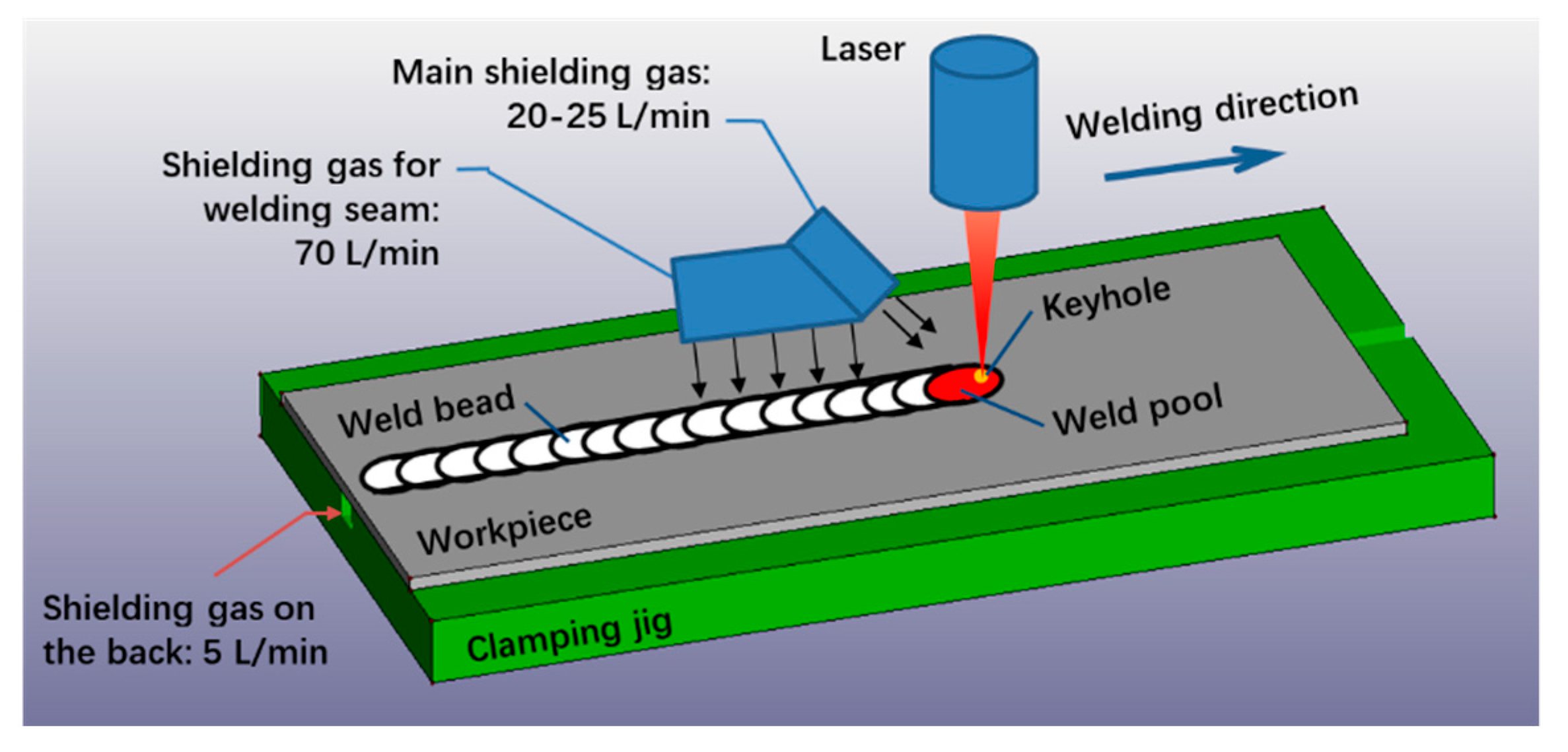
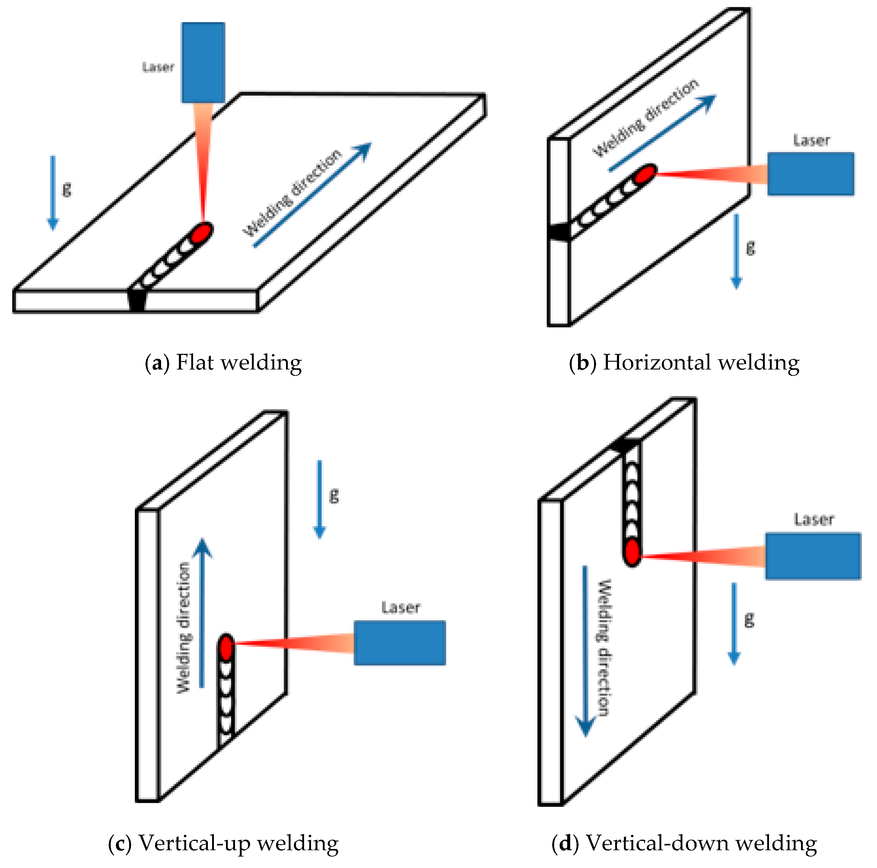
2.1. Experiments

Titanium alloy Ti6Al4V sheets were used to cut into welding work pieces, of which the dimensions were 300 mm × 150 mm × 3 mm, and the chemical composition is listed in Table 1.
The IPG YLS-6000 Yb fiber laser (IPG Photonics Corporation, Oxford, MA, USA) was used for laser welding trials, of which the maximum laser power was 6.0 kW. The wavelength of the output laser was 1070 ± 10 nm, the diameter of the optic fiber was 0.2 mm, and the diameter of the laser focal spot was 0.8 mm after the laser beam was collimated and focused.
Bead on plate (BOP) welding trials were performed as shown in Figure 1. High purity (99.99%) argon was used as shielding gas, and was supplied over three regions: the main stream was to shield the molten pool, the trailing stream to shield the high-temperature weld bead, and the back stream shielding the bottom surface of the work pieces.
Four welding positions were used in the welding experiments, i.e., flat welding, horizontal welding, vertical-up welding, and vertical-down welding, which are schematically shown in Figure 2.
Heat input, defined by the ratio of laser power to welding speed, is an important welding parameter. Three heat inputs generated by three sets of process parameters were used in the present study, as listed in Table 2. Higher laser powers and welding speeds were investigated in comparison with those used in previous studies [14], considering the capacity (6.0 kW) of the laser beam source.

2.2. Computational Fluid Dynamics (CFD) Numerical Modeling

2.2.1. Simplifications and Assumptions in Modeling

Laser welding is a very complex process that involves multiple phases (solid, liquid, and vapor) and complicated heat and mass transfer phenomena. To model this process, the necessary simplifications and assumptions were made as follows:
(1)
The fluid flow of the molten metal in weld pool was Newtonian, incompressible, and laminar.
(2)
The mass loss due to the metal vaporization was neglected.
(3)
Heat source and forces were applied directly on liquid and solid elements, but not on the vapor elements in the weld zone.

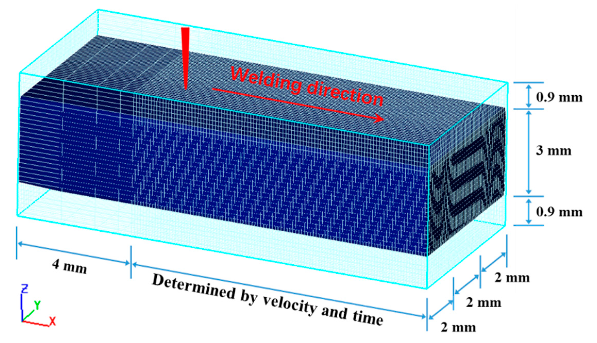
2.2.2. Computation Zone and Materials Property

The commercial CFD software Flow 3D was adopted as the platform, based on which the user subroutines were developed using Fortran language. Figure 3 shows the computational region and mesh constructed, of which the length can be adjusted for different process parameters. The mesh needs to be long enough to reach a quasi-stable state for the weld pool, when the length and width do not increase notably with time any more. To increase the computation speed, a non-uniform mesh was used: the weld zone had finer mesh division while the region away from the weld had coarser mesh. The minimum mesh cell was 0.1 mm × 0.1 mm × 0.15 mm. The mesh was fine enough to capture the influence of the heat source model on the keyhole and weld pool behavior, while it was not too fine to make the computation time impractically long. The void elements were used to model the vapor zone, which was assumed as a boundary with uniform pressure and temperature. The volume of fluid (VOF) method was used to trace the free surface of the molten pool.
The thermal and fluid flow property parameters of the titanium alloy Ti6Al4V use in the CFD are listed in Table 3.

2.2.3. Controlling Equations

The controlling equations for the heat transfer and fluid flow processes in the present laser welding of the titanium alloy are presented as follows:
Continuum equation:
( ρ ) t + ( ρ u ) x + ( ρ v ) y + ( ρ w ) z = 0
Conservation of momentum:
( ρ u ) t + ( ρ u u ) x + ( ρ v u ) y + ( ρ w u ) z = x ( μ u x ) + y ( μ u y ) + z ( μ u z ) P x + S x
( ρ v ) t + ( ρ u v ) x + ( ρ v v ) y + ( ρ w v ) z = x ( μ v x ) + y ( μ v y ) + z ( μ v z ) P y + S y
( ρ w ) t + ( ρ u w ) x + ( ρ v w ) y + ( ρ w w ) z = x ( μ w x ) + y ( μ w y ) + z ( μ w z ) P z + S z
Conservation of energy:
( ρ H ) t + ( ρ u H ) x + ( ρ v H ) y + ( ρ w H ) z = x ( k T x ) + y ( k T y ) + z ( k T z ) + S H
in which u, v, and w represent the components of velocity in x, y, and z directions, respectively. The ρ ,   P ,   H ,   k ,   μ are density, pressure, enthalpy, thermal conductivity, and viscosity. The Sm, SH, Sx, Sy, Sz are source terms in above equations.

Boundary Conditions

Thermal convective and radiation boundary conditions were applied on the outer surfaces of the workpiece as follows:
k T n = q convection + q radiation
In which, the convective heat flux is:
q c o n v e c t i o n = h c ( T T a )
The thermal radiative heat flux is:
q r a d i a t i o n = σ ε ( T 4 T a 4 )
where T is temperature, Ta is ambient temperature, hc is the convective heat transfer coefficient between the workpiece and the environment, σ is the Boltzmann constant, and ε is the emission coefficient of surfaces.

Heat Source Model

Considering the heat transfer between the laser beam and the workpiece takes place mainly on the surface of the keyhole in laser welding, the laser heat source was modelled as a heat flux applied on the keyhole surface, which varied with the keyhole depth, as described by Equation (9), which was adapted from a previous work [15].
q ( z ) = + + q ( x , y , z ) d x d y = + + 3 η P π a b d exp ( 3 x 2 a 2 ) exp ( 3 y 2 b 2 ) exp ( 3 z 2 d 2 ) d x d y = η P d exp ( 3 z 2 d 2 )
In the above model, P is laser power, η is the absorption coefficient of laser beam energy, parameters a and b are used to determine the energy distribution of the heat source, which are set to be the radius of the laser spot, and d is the depth of keyhole. The laser heat source moved at the welding speed, which was realized by programming in CFD modeling.

Force Models

Forces acting on the surface of keyhole mainly include vaporization recoiling pressure, surface tension, hydrostatic, and hydrodynamic pressures.
The recoiling pressure P r is obtained with the following Equation [16],
P r = 0.54 P 0 exp ( Δ H V T T V R T T V )
where P 0 is ambient pressure, Δ H V is the latent heat in vaporization, T is the temperature at keyhole surface, and R is the gas constant.
The surface tension P σ is a function of temperature, and was computed with the following Equation [15].
P σ ( T ) = 1.557 1.5 × 10 4 × ( T T m )
In which T is the temperature of keyhole surface, T m is the melting point of the material.
The gravity-dependent hydrostatic pressure and the velocity-dependent hydrodynamic pressure were already incorporated in the Flow 3D code. Various welding positions were modeled by applying the gravity in different directions, through which the relative direction between the weld pool and the gravity is changed, as well as the hydrostatic pressure.

Melting and Solidification Specification

Enthalpy-porosity method was used in the model to treat the melting and solidification phenomena. The elements with temperatures between the solidus and liquidus lines were treated as porous media, of which the fraction of liquid phase was fl that could be calculated according to the following equation:
f 1 = { 1 T > T l T T s T l T s T s > T > T l 0 T s > T
The latent heat was calculated according to Equation (13), and was then used as one source term in the energy equation.
Δ H s l = { L T > T l f 1 L T s > T > T l 0 T s > T

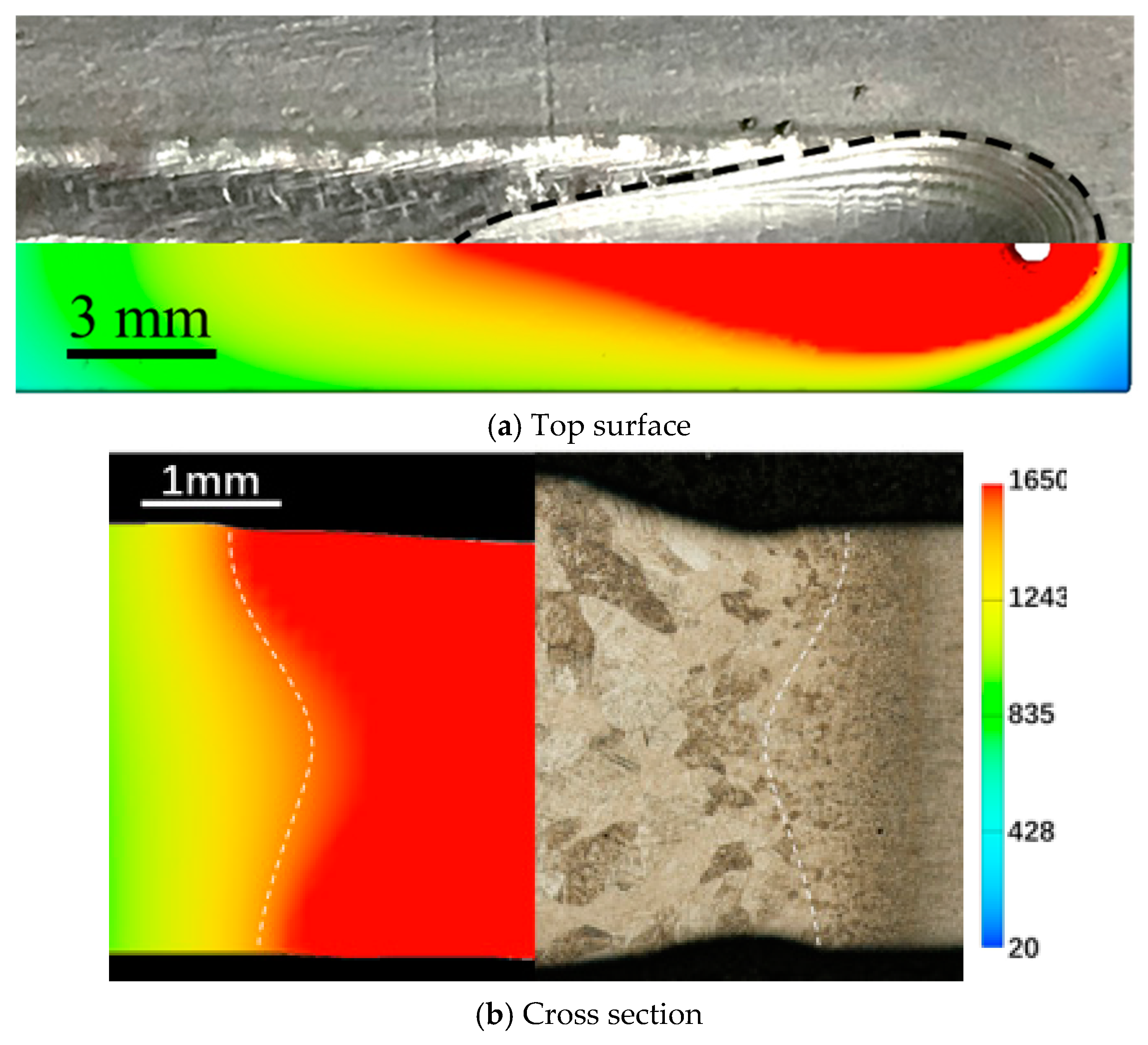
2.3. Validation of CFD Model

The accuracy of the CFD model was validated by a comparison between the numerically predicted weld pool profile with that experimentally obtained, as shown in Figure 4. It can be found that the shape and dimensions of the numerically obtained weld pool agree pretty well with those obtained experimentally, in terms of both the crater at the end and the cross section of the melt run produced with laser power of 4.0 kW and welding speed of 25 mm/s at the flat welding position.

3. Results and Discussion

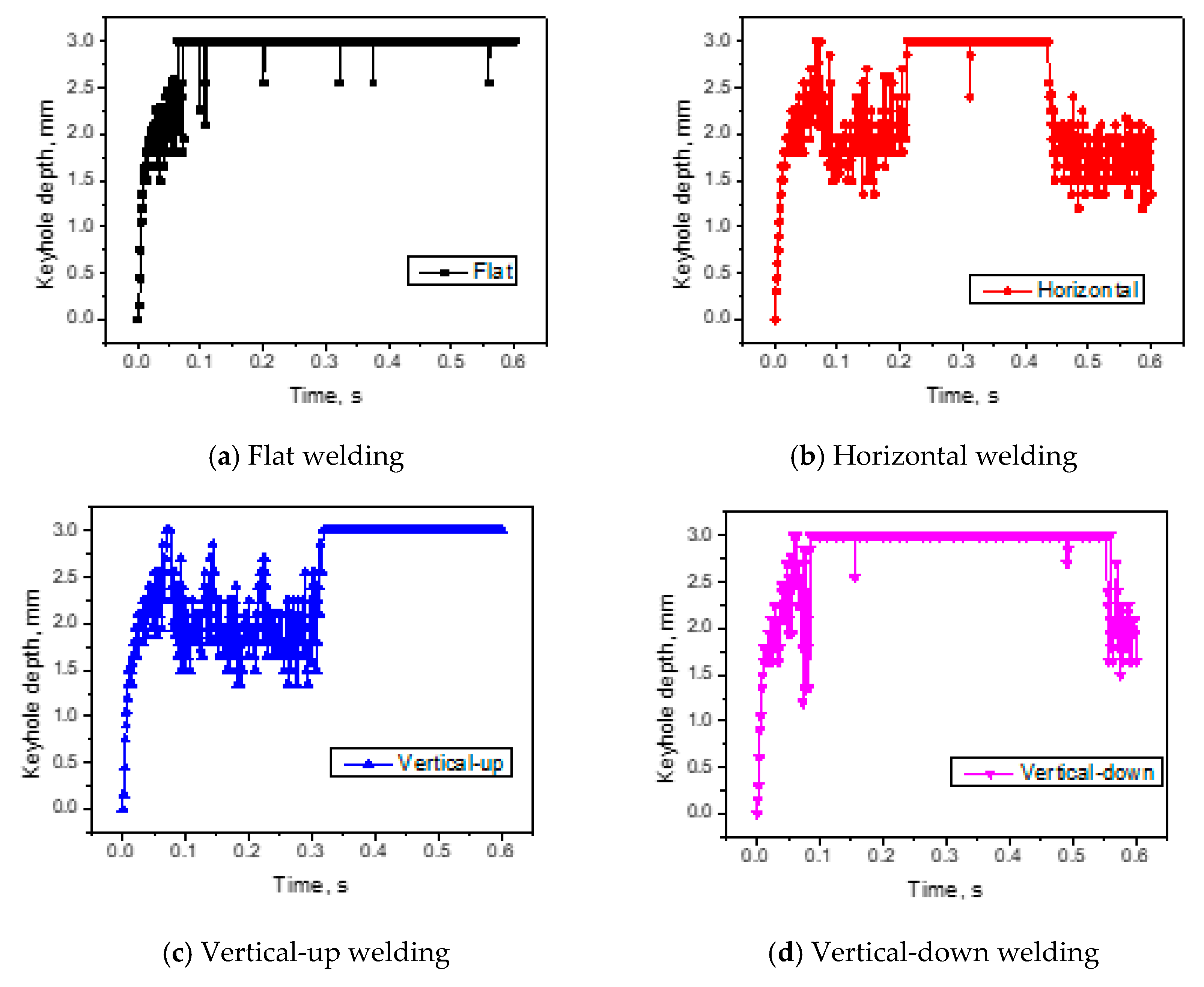
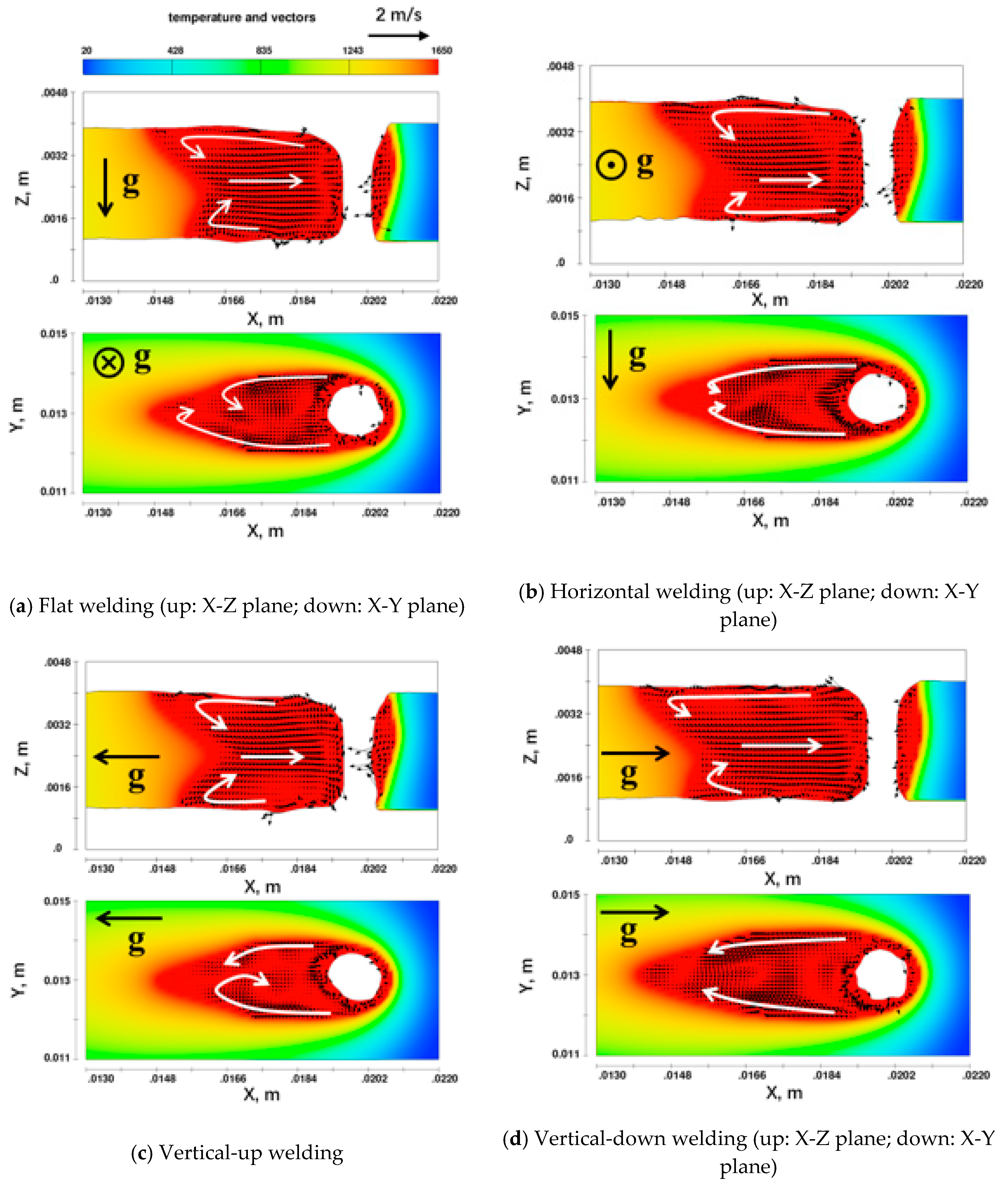
3.1. Keyholes and Weld Pool Behavior for Various Welding Positions with Small Heat Input

In laser welding, a weld pool will form under laser heating and a keyhole will form in the weld pool under the action of intense recoiling force. The depths of a keyhole will increase from zero at the beginning to the thickness of wokpiece when a full penetration state is reached. Due to the violent action of recoiling force, the molten metal around the keyhole surface moves dynamically, and under certain conditions, the full-penetration keyhole may collapse/close, making the keyhole depth decrease. Due to the different action directions of gravity on the molten metal for various welding positions, the dynamic behavior of a keyhole will change and, in turn, demonstrate different times/frequency of keyhole collapse, which can be reflected by the change in keyhole depth.
The variations of keyhole depths with time are presented in Figure 5 for laser welding under four welding positions and with the small heat input 85.7 J/mm (laser power 3.0 kW, welding speed 35 mm/s).
For all four welding positions, the keyhole depths increase quickly to 3.0 mm (the full penetration state), and the required time to reach full penetration is close for the four cases, which is in a range of 58–70 ms. After the full penetration state is reached, the keyhole depth may decrease from time to time during the subsequent welding process, which correspond to the closure or collapse of the keyhole.
For flat welding, the keyhole is stable and is open for most of the simulation time (0.6 s), except for a few (seven) times of short-period (1–3 ms) closures, which lead to small decreases in keyhole depth (mostly from 3.0 mm to 2.5 mm). The keyhole under the vertical-down position is also relatively stable, in which four times of keyhole fluctuations are found. However, the durations of keyhole closures are longer (>50 ms), and the depth fluctuations (from 3.0 mm to 1.2 mm) are larger than those of flat welding.
The keyholes are not as stable under horizontal and vertical-up welding positions when the full penetration state is just reached, with the keyhole depths fluctuating continuously. After a relatively stable keyhole is formed (after a welding time of about 0.3 s), its depths no longer vary for vertical-up welding position, but the continuous fluctuation of keyhole depth still exists for the horizontal welding position, showing a more unstable keyhole in horizontal welding.
From above analysis, it can be deduced that keyhole stability from the best to the worst is for flat, vertical-up, vertical-down, and horizontal welding positions. The keyhole is relatively stable for flat welding, which can be attributed to the axisymmetric distribution of gravity about the axis of the keyhole. In contrast, such axisymmetric distribution does not exist for the gravity when welding with the other three welding positions, which makes the movement of the molten metal around the keyhole less stable than that in flat welding.
The temperature distributions and fluid flow velocities are shown in Figure 6 for the four welding positions and small heat input, after the full penetration has reached and the keyhole is at an open state. For each welding position, the top plot is for the center plane of a specimen (X–Z plane), and the bottom is for the plane parallel to and 0.5 mm below the top surface of the specimen (X–Y plane).
For the flat welding position shown in Figure 6a, the molten metal neighboring the top and bottom surfaces of weld pool flows backward from the keyhole to the rear part of the weld pool in the center plane; at the rear part, the molten metal flows first inward to the thickness center, then forward to the keyhole.
Similarly, in the horizontal plane (X–Y plane), the molten metal close to the boundaries of the weld pool flows backward from the keyhole to the rear part of the weld pool, where the fluid flow changes direction and moves inward the weld pool. The forward flow is not very significant nearby the centerline of the weld pool.
Similar flow patterns can be found for the other three welding positions. The shapes and dimensions of the weld pools are also quite close for different welding positions. Obviously, when the small heat input is used, the change of welding position, or the change of the orientation of the weld pool relative to that of gravity, will not notably affect the temperature and fluid flow fields of the laser weld pool. This finding is the same as that reported by Sohail el al. [5] when they studied the influences of welding position in laser welding of steel. Such an irrelevance of welding positions to the weld pool behavior should also be attributed to the relatively small heat input used in their study.

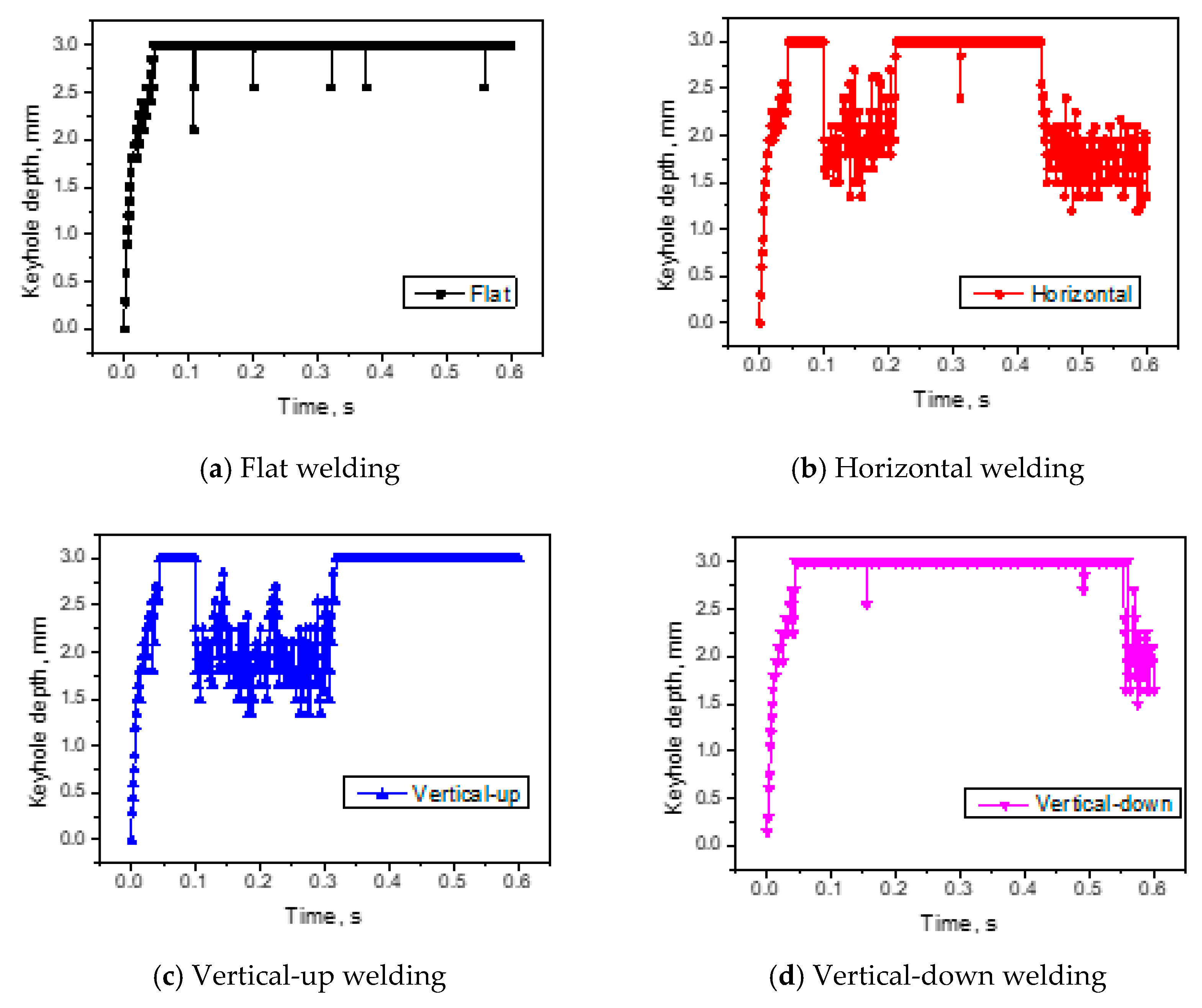
3.2. Keyholes and Weld Pool Behavior for Various Welding Positions with Large Heat Input

Figure 7 presents the variation of keyhole depth with time for laser welding of 3.0 mm thick titanium alloy Ti6Al4V under four welding positions and with a relatively large heat input of 160 J/mm (laser power 4.0 kW, welding speed 25 mm/s).
It can be found from the figures that for a given welding position, increasing the heat input from 85.7 to 160 J/mm does not change the variation trend of keyhole depth with time, but the time required to form fully penetrated keyholes was shortened to about 44–47 ms, which is about 20% less than those for small heat input. Meanwhile, the fluctuation of keyhole depth in reaching full penetration is smaller at the beginning period of welding, which indicating a more stable keyhole when the heat input is increased.
Moreover, it can be observed that increasing the heat input by increasing laser power and decreasing welding speed could increase the time period when the keyhole is open, while decreasing the time period when the keyhole is closed/collapsed; the fluctuation amplitudes of keyhole depth are reduced at the same time. This is especially true for the horizontal and vertical-up welding in which the keyhole is not stable at the beginning stage of welding. Obviously, the keyhole stability can be improved by increasing the heat input. This can be attributed to the increased recoiling pressure under higher laser power, which can better suppress the disturbance on keyhole by the asymmetric gravity.
Shen et al. [3] has found in their study on laser welding of thick steel sheets that higher heat input was required for horizontal welding than for flat welding. The CFD results from this study indicate that keyhole is quite instable in horizontal welding in comparison with flat welding. This means a heat input that can just produce a fully penetrated weld at the flat-welding position may only produce an intermittent penetration weld at horizontal welding position. An increase in the heat input can increase the keyhole stability and result in a fully penetrated horizontal weld. The numerical results clearly reveal the substantial causes of the experimental finding.
Figure 8 shows the temperature and fluid flow fields under four welding positions with a larger heat input 160 J/mm (4.0 kW, 25 mm/s). For flat welding, increasing the laser heat input from 85.7 to 160 J/mm significantly increases the length and width of weld pool: the length is increased from 6.4 mm to 13.5 mm, and the width is increased from 2.2 mm to 4.6 mm. The molten metal still flows roughly from the front to the rear of the weld pool along both top and bottom surfaces of the workpiece in the X–Z plane and along the boundaries of weld pool in the X–Y plane, but the fluid flow has become much more turbulent than that formed with small heat input.
Similar dimensions and fluid flow are found for the horizontal weld pool with those for flat welding with large heat input. The shape of the weld pool in vertical-up welding is quite different from those at other welding positions: the length of weld pool on top surface is remarkably larger than that on bottom surface, reflecting the much more turbulent metal flow in the weld pool. Meanwhile, the backward flow of molten metal to the rear part of the weld pool in vertical-up welding is notably enforced by the action of gravity, making the molten metal become less around the keyhole: the thicknesses of molten metal neighboring the backside surface of keyhole becomes thinner in workpiece thickness (Z) direction, and the motel metal in front of the keyhole also becomes thinner in the advancing direction (X) of the laser, as shown in Figure 8c. On the contrary, the forward flow of molten metal to the keyhole is enforced by the gravity action in vertical-down welding, and the molten metal tends to accumulate around the keyhole. As a result, the thicknesses of molten metal around the keyhole are larger in both X and Z directions in comparison with other welding positions, as shown in Figure 8d. The thicknesses of molten metal around the keyhole for flat and horizontal welding positions lie in between those for vertical-up and vertical-down welding positions.
It can be seen by comparing Figure 6 with Figure 8 that although the influence of welding position is negligible when the laser heat input is small, it becomes significant when the heat input is large. Both profiles and fluid flows of the weld pool are noticeably changed by employing different welding positions, especially the vertical welding positions.

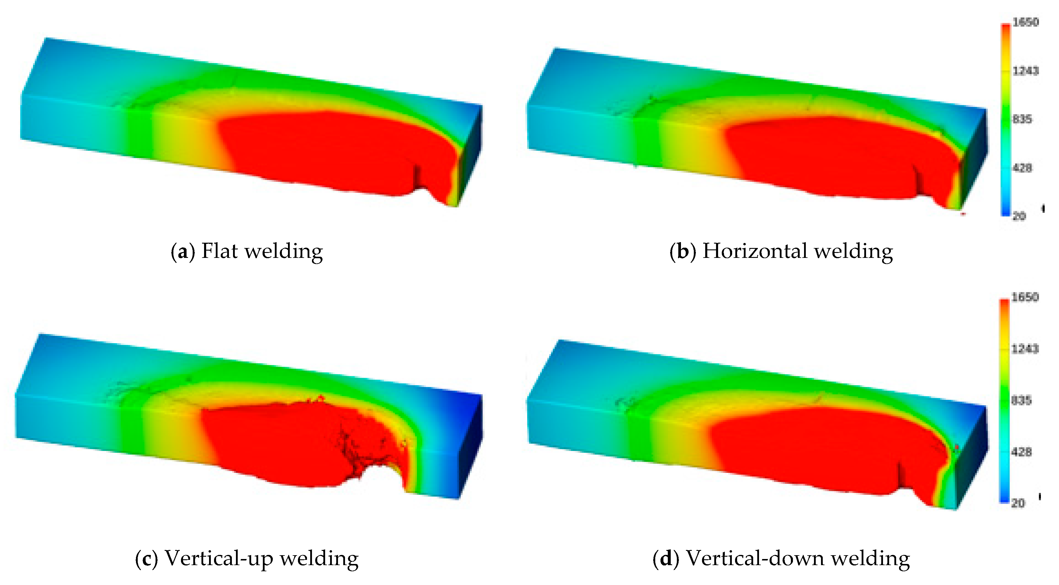
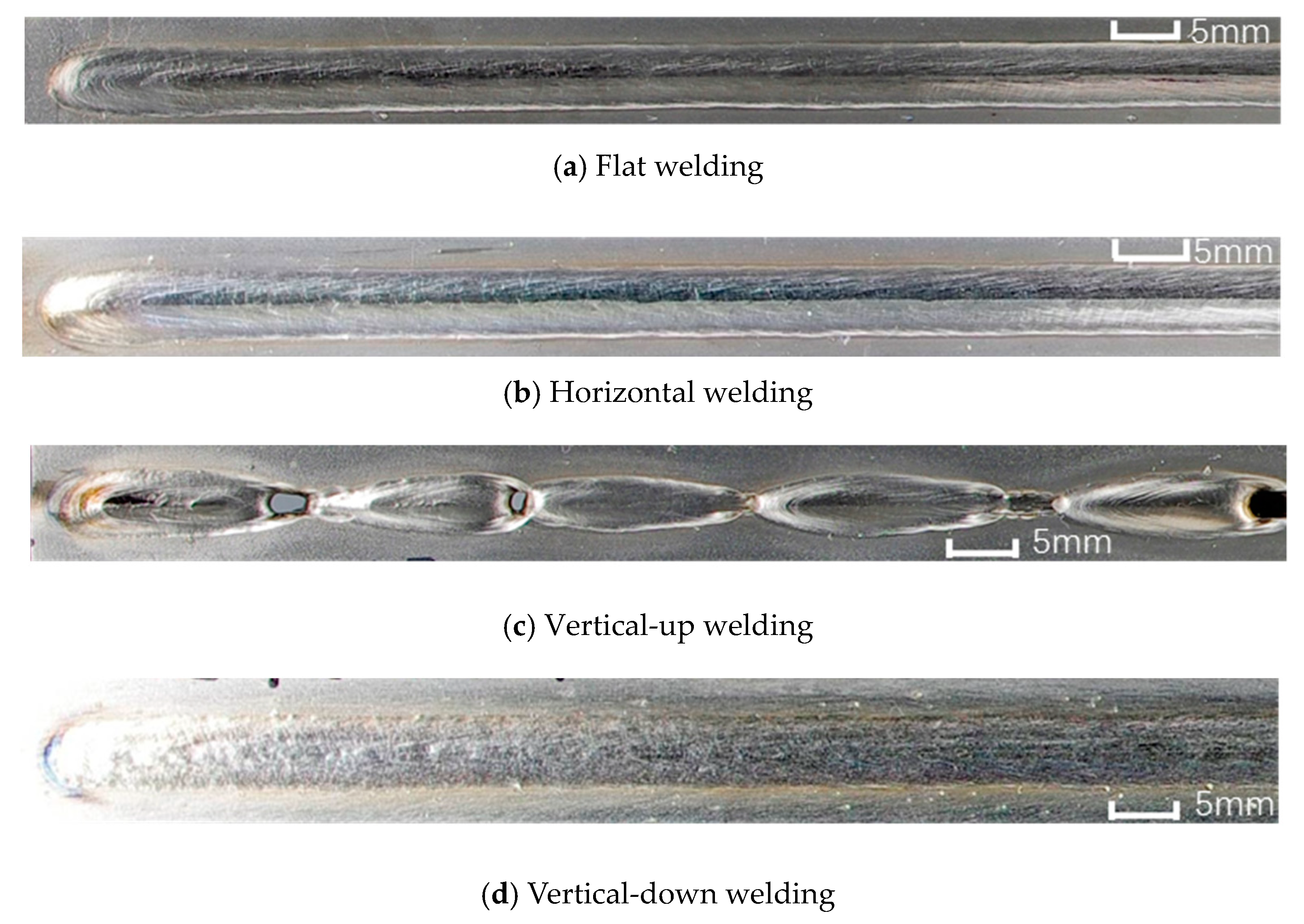
3.3. Laser Welding with too High a Heat Input

As found from above numerical modeling, the keyhole and weld pool will be affected notably by welding positions when the heat input is relatively high. A further increase in the heat input to 210 J/mm (4.2 kW, 20 mm/s) was investigated by CFD and the one half of the workpiece is shown in Figure 9, demonstrating the profiles of keyhole and weld pool for each of the four welding conditions. An excessive increase in keyhole size and an excessive decrease in the amount of molten metal ahead of the keyhole can be observed for the vertical-up welding condition in Figure 9c, while the shapes and dimensions of weld pools are normal and similar for the other three welding positions, as shown in Figure 9a,b,d.
The weld beads experimentally obtained with the heat input of 210 J/mm (4.2 kW, 20 mm/s) at four welding positions are shown in Figure 10. Periodic occurrence of burn-through holes is evident in the vertical-up weld. In contrast, good weld formation is obtained with the other welding positions. The experimental observation agrees very well with the numerical prediction.

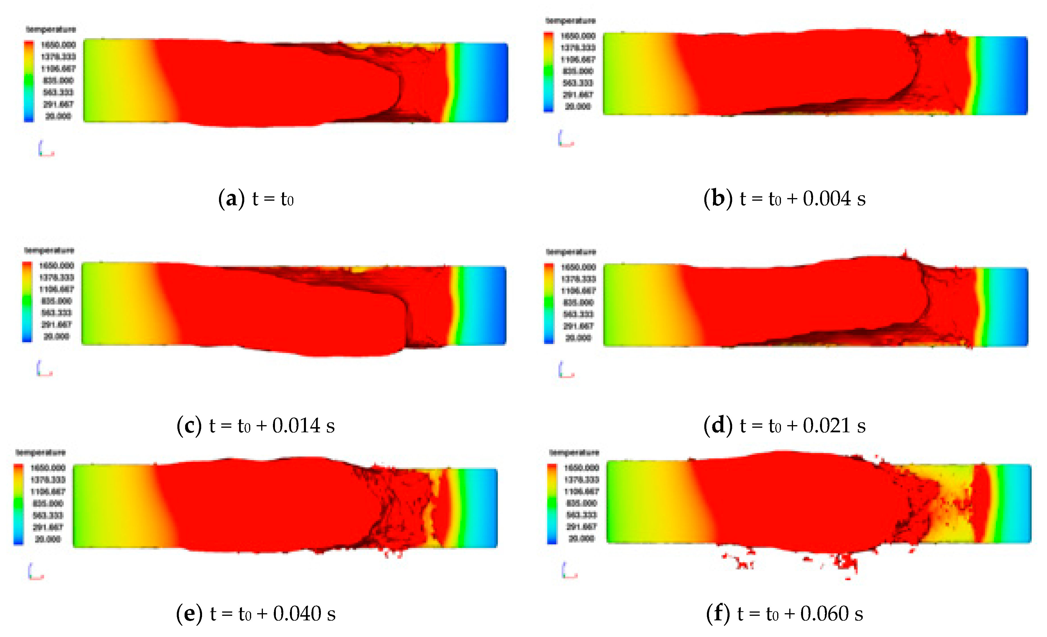
3.4. Formation Process of Burn-Through Holes in Vertical-Up Welding

The evolution of the instable weld pool and keyhole in vertical-up laser welding of Ti6Al4V was studied with CFD. Figure 11 shows the profiles of weld pool and keyhole observed from the center plane of a specimen (X–Z plane) at several time steps during vertical-up welding with the very high heat input of 210 J/mm.
At a time step t0, the molten metal nearby the keyhole becomes thin under gravity action, while those at the rear part of the weld pool become thick. At time t0 + 0.004 s, the molten metal in the middle part of weld pool moves upward (in +Z direction) to a maximum height, which is 0.30 mm above the top surface of the workpiece, then begins to move downward (in the −Z direction). At t = t0 + 0.014 s, the molten metal moves to the maximum point in the opposite direction, which is 0.45 mm beyond the bottom surface of workpiece, and subsequently moves upward again. Clearly, oscillation of molten metal occurs in the thickness direction of workpiece, during which the molten metal nearby the keyhole may fly out of the weld pool, and result in mass loss. At time t0 + 0.04 s, a yellow part appears at the front surface of the keyhole, indicating no molten metal exists there due to the excessive backward movement and mass loss of molten metal. The area of unmelted metal is even larger at time of t0 + 0.06 s, indicating the molten metal flow is disrupted and no molten metal will continue to flow around the keyhole. In other words, a burn-through hole is formed.
From the present study, it is found that small heat input may generate an unstable keyhole that collapses frequently in welding, which may result in porosity in welds. An increase in heat input can increase the stability of the keyhole, and in turn reduce the porosity. Besides, the vertical-up welding position has been previously shown to be a better choice than the horizontal and the vertical-down positions to avoid the occurrence of porosity in laser welding of titanium alloys, due to the existence of escape routes for bubbles in vertical-up welding. However, it has been demonstrated here that the vertical-up laser welding with a too big heat input will lead to very turbulent fluid flow in the weld pool, and result in poor bead formation in terms of burn-through holes. Therefore, a moderate heat input should be used for vertical-up welding, which is high enough to generate a stable keyhole to reduce the porosity but not too high in order to avoid the occurrence of burn-through holes.

4. Conclusions

In the present study, the influences of four welding positions (flat, horizontal, vertical-up, and vertical-down) on the keyhole and weld-pool behavior were studied with a CFD model for three heat inputs (small, large, and too high), based on which the following conclusions can be drawn:
(1)
As for the four welding positions studied in the study, the stability of keyhole is the best for flat welding, moderate for vertical-up and vertical-down welding, and the worst for horizontal welding. Increasing heat input may increase the keyhole stability by increasing laser power and decreasing welding speed.
(2)
When heat input is small, the influence of welding position is negligible on the keyhole and weld-pool behavior; when the heat input is large, the influences of gravity on the molten metal become significant, especially when the vertical welding positions are used.
(3)
When too high a heat input is used in vertical-up welding, the molten metal around the keyhole will oscillate and break away from the weld pool, which will lead to separation of molten metal near the keyhole and result in burn-through holes in welds.
(4)
A moderate heat input should be taken in positional laser welding of titanium alloys, which is high enough to generate a stable keyhole, but not too high in order to guarantee formation quality.

Author Contributions

Formal analysis, B.C.; investigation, H.C. and H.L.; methodology, D.D. and J.S.; software, Z.Y.

Funding

This research was funded by the National Natural Science Foundation of China, grant number U1537205 and 51675303. The APC was funded by U1537205.

Conflicts of Interest

The authors declare no conflict of interest.

References

  1. Leyens, C.; Peters, M. Titanium Alloys for Aerospace Applications. In Titanium and Titanium Alloys: Fundamentals and Applications; Christoph, L., Manfred, P., Eds.; John Wiley & Sons: Hoboken, NJ, USA, 2003. [Google Scholar]
  2. Goussain, J.C.; Becker, A.; Chehaibou, A.; Leca, P. Heavy-section welding with very high power laser beams: The challenge. In Proceedings of the SPIE–The International Society for Optical Engineering, Munich, Germany, 16–20 June 1997. [Google Scholar]
  3. Shen, X.F.; Li, L.; Guo, W.; Teng, W.H.; He, W.P. Comparison of processing window and porosity distribution in laser welding of 10 mm thick 30CrMnSiA ultrahigh strength between flat (1G) and horizontal (2G) positions. J. Laser Appl. 2016, 28, 022418. [Google Scholar] [CrossRef]
  4. Guo, W.; Liu, Q.; Francis, J.A.; Crowther, D.; Thompson, A.; Liu, Z.; Li, L. Comparison of laser welds in thick section S700 high-strength steel manufactured in flat (1G) and horizontal (2G) positions. CIRP Ann. Manuf. Technol. 2015, 64, 197–200. [Google Scholar] [CrossRef]
  5. Sohail, M.; Han, S.W.; Na, S.J.; Gumenyuk, A.; Rethmeier, M. Numerical investigation of energy input characteristics for high-power fiber laser welding at different positions. Int. J. Adv. Manuf. Technol. 2015, 80, 931–946. [Google Scholar] [CrossRef]
  6. Chang, B.H.; Yuan, Z.; Pu, H.T.; Li, H.G.; Cheng, H.; Du, D.; Shan, J.G. A comparative study on the laser welding of Ti6Al4V alloy sheets in flat and horizontal positions. Appl. Sci. 2017, 7, 376. [Google Scholar] [CrossRef]
  7. Chang, B.H.; Yuan, Z.; Pu, H.T.; Li, H.G.; Cheng, H.; Du, D.; Shan, J.G. Study of gravity effects on titanium laser welding in the vertical position. Materials 2017, 10, 1031. [Google Scholar] [CrossRef] [PubMed]
  8. Katayama, S.; Mizutani, M.; Matsunawa, A. Development of porosity prevention procedures during laser welding. In Proceedings of the lamp 2002 International Congress on Laser Advanced Materials Processing, Osaka, Japan, 27–31 May 2002. [Google Scholar]
  9. Wu, D.S.; Hua, X.M.; Huang, L.J.; Zhao, J. Numerical simulation of spatter formation during fiber laser welding of 5083 aluminum alloy at full penetration condition. Opt. Laser Technol. 2018, 100, 157–164. [Google Scholar] [CrossRef] [Green Version]
  10. Huang, L.J.; Hua, X.M.; Wu, D.S.; Li, F. Numerical study of keyhole instability and porosity formation mechanism in laser welding of aluminum alloy and steel. J. Mater. Process. Technol. 2018, 252, 421–431. [Google Scholar] [CrossRef]
  11. Wu, D.S.; Hua, X.M.; Li, F.; Huang, L.J. Understanding of spatter formation in fiber laser welding of 5083 aluminum alloy. Int. J. Heat Mass Transf. 2017, 113, 730–740. [Google Scholar] [CrossRef]
  12. Pang, S.Y.; Chen, L.L.; Zhou, J.X.; Yin, Y.J.; Chen, T. A three-dimensional sharp interface model for self-consistent keyhole and weld pool dynamics in deep penetration laser welding. J. Phys. D Appl. Phys. 2011, 44, 025301. [Google Scholar] [CrossRef]
  13. Pang, S.Y.; Chen, W.D.; Wang, W. A quantitative model of keyhole instability induced porosity in laser welding of titanium alloy. Metall. Mater. Trans. A Phys. Metall. Mater. Sci. 2014, 45, 2808–2818. [Google Scholar] [CrossRef]
  14. Wen, P.; Yelkenci, D.; Chen, J.H.; Chang, B.H.; Du, D.; Shan, J.G. Numerical analysis of the effect of welding positions on formation quality during laser welding of TC4 titanium alloy parts in aerospace industry. J. Laser Appl. 2019, 31, 022401. [Google Scholar] [CrossRef]
  15. Chang, B.H.; Allen, C.; Blackburn, J.; Hilton, P.; Du, D. Fluid flow characteristics and porosity behavior in full penetration laser welding of a titanium alloy. Metall. Mater. Trans. B Process. Metall. Mater. Process. Sci. 2015, 46, 906–918. [Google Scholar] [CrossRef]
  16. Jin, X.Z.; Li, L.J.; Zhang, Y. A study on fresnel absorption and reflections in the keyhole in deep penetration laser welding. J. Phys. D Appl. Phys. 2002, 35, 2304–2310. [Google Scholar] [CrossRef]
Figure 1. Schematic diagram of laser welding.
Metals 09 01082 g001
Figure 2. Four welding positions employed in the present study.
Metals 09 01082 g002
Figure 3. The computation zone used in computational fluid dynamics (CFD) simulation.
Metals 09 01082 g003
Figure 4. Comparison of the numerically predicted and the experimentally obtained weld pool profiles on the top surface (a) and cross section (b) for laser welding of Ti6Al4V under the flat welding position (4.0 kW, 25 mm/s).
Metals 09 01082 g004
Figure 5. Variation of keyhole depths with time when laser welding using four different welding positions conditions: (a) Flat welding; (b) Horizontal welding; (c) Vertical-up welding; (d) Vertical-down welding, with a small heat input 85.7 J/mm (3.0 kW, 35 mm/s).
Metals 09 01082 g005
Figure 6. Morphologies of the weld pools for different welding positions: (a) Flat welding; (b) Horizontal welding; (c) Vertical-up welding; (d) Vertical-down welding, when laser welding with a small heat input 85.7 J/mm (3.0 kW, 35 mm/s).
Metals 09 01082 g006
Figure 7. Variation of keyhole depths with time when laser welding using four different welding positions: (a) Flat welding; (b) Horizontal welding; (c) Vertical-up welding; (d) Vertical-down welding, with a large heat input 160 J/mm (4.0 kW, 25 mm/s).
Metals 09 01082 g007
Figure 8. Morphologies of the weld pools for different welding positions: (a) Flat welding; (b) Horizontal welding; (c) Vertical-up welding; (d) Vertical-down welding, when laser welding with the high heat input 160 J/mm (4.0 kW, 25 mm/s).
Metals 09 01082 g008aMetals 09 01082 g008b
Figure 9. Morphologies of the keyholes and weld pools for different welding positions: (a) Flat welding; (b) Horizontal welding; (c) Vertical-up welding; (d) Vertical-down welding, when laser welding with the too high heat input 210 J/mm (4.2 kW, 20 mm/s).
Metals 09 01082 g009
Figure 10. Surface appearance of laser melt runs produced with four different welding positions: (a) Flat welding; (b) Horizontal welding; (c) Vertical-up welding; (d) Vertical-down welding, with the too high heat input 210 J/mm (4.2 kW, 20 mm/s).
Metals 09 01082 g010
Figure 11. Morphologies of keyhole and weld pool at different time steps: (a) t = t0; (b) t = t0 + 0.004 s; (c) t = t0 + 0.014 s; (d) t = t0 + 0.021 s; (e) t = t0 + 0.040 s; (f) t = t0 + 0.060 s, during vertical-up laser welding.
Metals 09 01082 g011
Table 1. Chemical composition of Ti6Al4V titanium alloy.
ElementsCHONFeAlVTi
Content, wt%0.050.0110.190.030.205.84.0Bal.
Table 2. Process parameters of laser welding used in the study.
NumberLaser Power, kWWelding Speed, mm/sDefocusing Distance, mmHeat Input, J/mm
Set 13.035085.7 (Small)
Set 24.0250160 (Large)
Set 34.2200210 (Too high)
Table 3. Material properties parameters of Ti6Al4V used in CFD simulation, adapted from [15].
Material PropertyValues
Density ρ, kg/m34420
Viscosity μ, kg/(m⋅s)0.00325
Specific Heat Cp, J/(kg⋅K)546
Thermal Conductivity λ, W/(m⋅K)34.6
Melting Temperature Tm, °C1650
Melting enthalpy ΔHsl, J/kg 2.86 × 10 5
Evaporation temperature Tv, °C3287
Evaporation enthalpy ΔHv, J/kg 2.84 × 10 7
Surface tension coefficient Pσ, N/m P σ ( T ) = 1.557 1.5 × 10 4 × ( T T m )

