Review

An Introduction to Wear Degradation Mechanisms of Surface-Protected Metallic Components

by
Pandora P. Psyllaki
Department of Mechanical Engineering, University of West Attica, 250 Thivon avenue & P. Ralli, 12244 Egaleo, Greece
Metals 2019, 9(10), 1057; https://doi.org/10.3390/met9101057
Submission received: 1 September 2019 / Revised: 18 September 2019 / Accepted: 25 September 2019 / Published: 28 September 2019
(This article belongs to the Special Issue Failure Mechanisms in Alloys)

Abstract

:
Despite the fact that ceramics and polymers have found numerous applications in several mechanical systems, metals and metallic alloys still remain the main materials family for manufacturing the bulk of parts and components of engineering assemblies. However, in cases of components that are serving as parts of a tribosystem, the application of surface modification techniques is required to ensure their unhampered function during operation. After a short introduction on fundamental aspects of tribology, this review article delves further into four representative case studies, where the inappropriate application of wear protection techniques has led to acceleration of the degradation of the quasi-protected metallic material. The first deals with the effects of the deficient lubrication of rolling bearings designed to function under oil lubrication conditions; the second is focused on the effects of overloading on sliding bearing surfaces, wear-protected via nitrocarburizing; the third concerns the application of welding techniques for producing hardfacing overlayers intended for the wear protection of heavily loaded, non-lubricated surfaces; the fourth deals with the degradation of thermal-sprayed ceramic coatings, commonly used as wear-resistant layers.

1. Introduction

The term “tribosystem” or “tribopair” is commonly used to describe the conjugated function of two components that are moving relevant to each other [1]. Although in general, one element of the tribosystem could be in the fluid state, e.g., natural gas moving in a pipeline, in the majority of mechanical systems both elements are in the solid state and their coupled operation serves to transfer motion, power, or mechanical loading; thus, a typical tribosystem is schematically presented in Figure 1a.
A tribosystem is defined by (a) the geometry of the participating elements, (b) their relevant geometry that defines the contact as either conformal or contra-formal, (c) the microgeometry of the surfaces in contact (roughness, Figure 1b), and (d) the construction materials of the two elements and the degree of their hardening. Each such tribopair can perform under various operational parameters that combine the normal load applied (F), the relevant speed (v), and the intervention of a third medium (solid or fluid) at the area between the two in-contact surfaces [1]. Finally, the operation of the tribosystem is carried out in a particular surrounding environment that is characterized by the level of relevant humidity (% RH) and temperature, or even by the application of vacuum. Depending on the type of the relevant motion, the tribosystems in mechanical engineering can be generally divided into rolling or sliding bearings.
The resistance to the relevant motion between the two elements is reflected in the friction coefficient value (μ), which is equal to the ratio of the normal load applied to the friction force that appears ( μ = F T ). The higher the friction coefficient, the higher is the energy consumption for keeping the motion ongoing [2]. Under these conditions, the operation of the tribosystem leads simultaneously to material removal from the two conjugated surfaces, i.e., material losses [3]. In the meantime, the application of a normal load at the contact surface leads to a distribution of applied pressure that results in a distribution of normal and shear stresses within the upper surface layers of the two solids in contact; the former are maximized on the contact area, while the latter are maximized at a depth below the contact area of the two solids [1,2,3,4]. This fact could result in crack initiation and propagation during the operation of a tribosystem.
Depending on the particular application of each tribo-assembly, the requirement could be for either low or high friction coefficient values, i.e., cutting tools or brakes, respectively, either low or high wear values, i.e., brakes or workpiece, respectively. In all cases, the stable operation of the tribosystem requires a constant friction coefficient and uniform wear rates during function, as well as normal and shear stresses lower than the yield point of the construction materials of the two conjugated elements and significant durability when operating in the fatigue regime. The combined effect of the friction force, the normal and shear stresses, and the adhesion forces developed between the two elements define the wear micro-mechanisms that are activated on the contact area, leading to material removal from both conjugated surfaces [3].
The topography and the mechanical properties of the surface are of crucial importance for the operation, since they determine the stress distribution, the ease of relevant motion, and the wear rate and mechanisms that affect the surface and sub-surface crack initiation and propagation, energy consumption, and material losses, respectively. In order to enhance the performance of such bearing surfaces, several modification techniques are available, involving liquid or solid compounds that alter the distribution of surface stresses, the relevant motion, and/or material removal, but not the mechanical properties of the bulk metal of the entire structure. Even though such surface modification techniques do have a beneficial effect on engineering surfaces, their inappropriate application or their erroneous selection for a particular application, render their involvement in the tribosystem a rather detrimental factor for the integrity of the entire structure.
In order to overcome undesirable premature failure during the operation of a tribosystem consisting of two conjugated metallic solids, it is recommended to modify the properties of their surfaces exposed to the action of the above-mentioned facts. The most widely applied techniques that result in mainly the reduction of the friction force—thus, reduction of the friction coefficient and consequently diminution of the energy demands for motion sustainability—consist of the application of a lubricant medium between the two conjugated surfaces [2]. The main categories of lubrication, representative media, and common applications for each one are presented in Table 1.
To ensure their effectiveness, both solid and liquid lubricants should, mainly, exhibit effective adherence to the contact surfaces of the conjugated solids, coherence under the normal and shear stresses and compositional stability at the temperature range to be developed during operation of the tribosystem.
During the last decades, several surface modification techniques [4,5,6,7] were developed aiming to reduce the wear rate of the material of the main construction by several orders of magnitude, not necessarily leading to a decrease of the friction coefficient. The majority of these techniques are based on the creation of a surface overlayer on the initial material; the former being much more wear resistant than the latter. In this way, the service lifetime of the elements of the tribopair is prolonged and, in some cases, this “protective” surface layer can be easily replaced without any adverse effect on the metal of the main structure. In general, the thickness of such overlayers is smaller compared to the dimensions of the main structure; however, these are efficient to expand significantly the service lifetime of the elements, without crucial dimensional changes of the main components. The main categories of these techniques, representative surface layers, and respective applications are presented in Table 2.
In particular, the typical coatings obtained via PVD, CVD, and plating (electrolytic or electroless) contribute not only to wear resistance but also to the reduction of the friction coefficient. Despite the fact that both approaches, i.e., lubrication and coatings deposition, contribute significantly to the protection of the metal of the basic construction, their inadequate application or their use under non-recommended operating conditions would lead to the acceleration of degradation of the metallic structure to be protected and to premature catastrophic failure of the elements of the tribosystem. Four relevant case studies that emphasize the degradation of metallic components of representative wear-protected elements due to the failure of the protection are discussed below, the main aim being to present, in a unified and coherent way, the detrimental effects on the performance of tribo-elements that should have exhibited prolonged lifetime after the application of a surface protection technique.

2. Synopsis of Experimental Techniques

It is generally admitted that in cases of severe degradation, the root cause of failure could be accurately determined by observing the failed system at low magnification or even by optical inspection, whilst observations at higher magnifications or complementary diagnostic techniques can be applied in order to further elucidate mechanisms that are unclear, vague, and not widely known. For this purpose and on a case-by-case basis, the experimental techniques applied in the following representative examples comprised:
(1)
Visual inspection and stereomicroscopic (Leica MS 5,Leica Microsystems GmbH, Wetzlar, Germany) and optical (Olympus BX60, Olympus Corporation, Tokyo, Japan) observations for determining the material’s failure areas that could provide information on the root cause, as well as areas that merit further laboratory examination.
(2)
Scanning electron microscopy (SEM, JEOL 840A, Jeol Ltd, Tokyo, Japan) coupled with elemental micro-analysis (EDS, OXFORD INCA 300, Oxford Instruments, Abingon, UK) and X-ray diffraction (XRD, Siemens D-800, Siemens AG, Munich, Germany) analysis of selected areas, for revealing the material’s flaws or transformations that accelerated failure.
(3)
Ball-on-disc tribological measurements (Centre Suiss d′ Electronique et de Microtechnique, CSEM SA, Neuchâtel, Switzerland), for evaluating the performance of wear-resistant protective coatings before service.

3. Case Study I: Failure of Lubricated Rolling Bearings

3.1. Fundamentals of Liquid Lubrication

Already since 1902, Stribeck [8] proposed a model for lubricated friction that describes the behavior of a tribosystem in terms of friction coefficient, taking into account the combined factor ( η v P ) of the operational parameters, where (η) is the viscosity of the lubricant, (v) the rotation speed, and (P) the load per unit of the projected bearing area.
As can be observed in Figure 2, depending on the operational parameters, each particular lubricated tribosystem exhibits a wide range of friction coefficient values that correspond to three different lubrication regimes [2]:
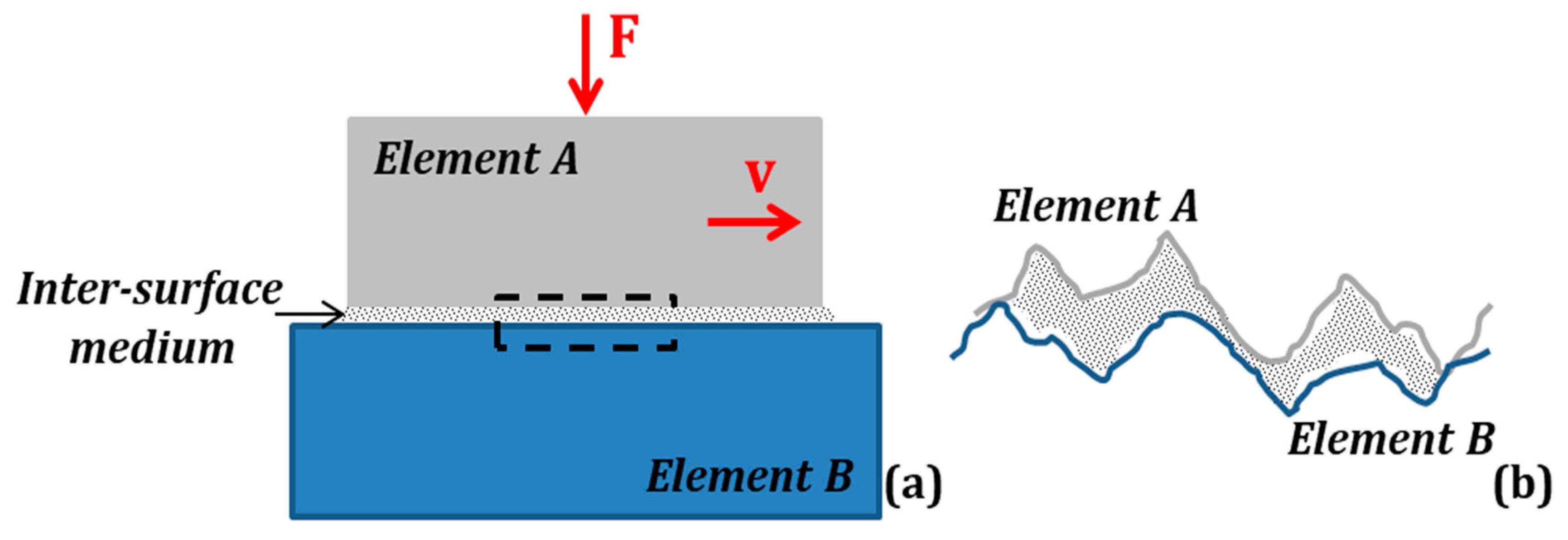
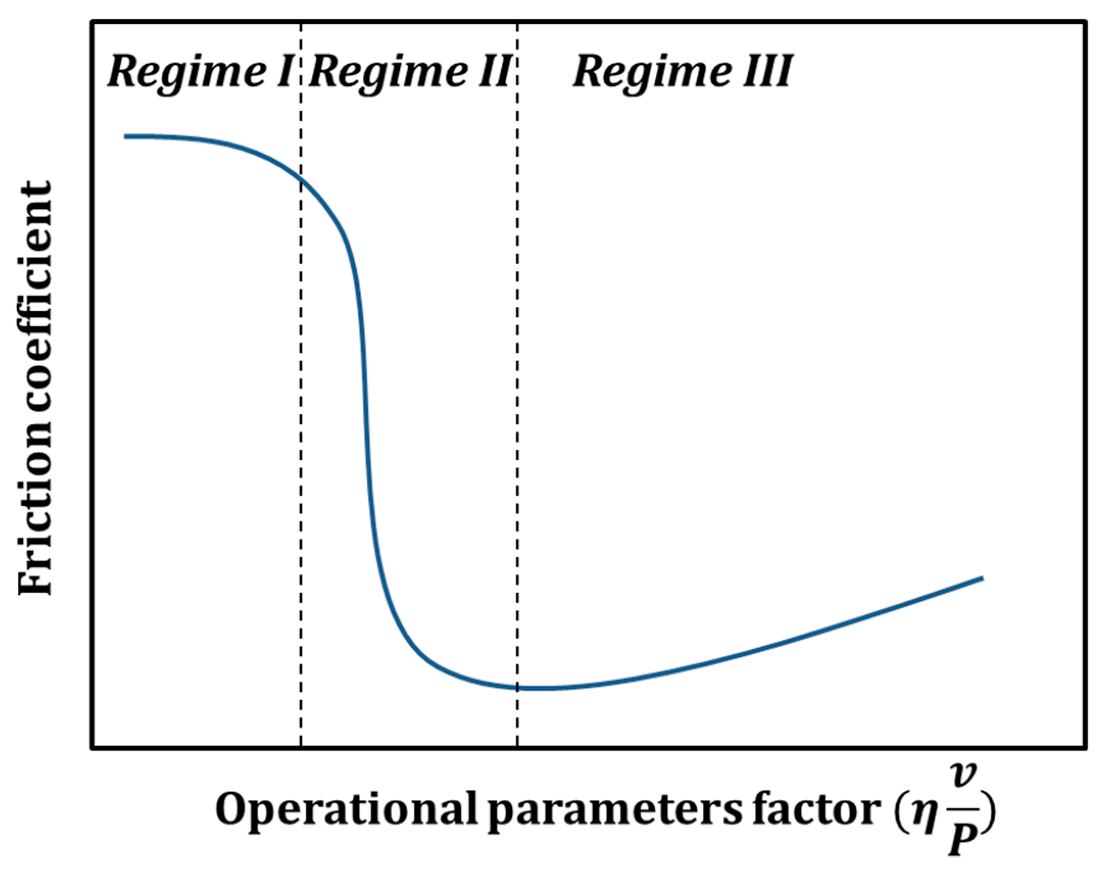
  • Within regime I, also known as boundary lubrication, the friction coefficient value tends to be similar to that under non-lubricating conditions. The thickness of the lubrication film is very thin, the load is taken on exclusively by the two solids and is transferred from the one to the other trough the contact between their surface asperities; thus, the rheological characteristics of the lubricant do not intervene and the lubrication efficacy depends only on the physicochemical characteristics of the liquid. These exactly “quasi-dry” lubrication conditions result in severe wear of the two solids.
  • Within regime II, also known as mixed or partial elasto-hydrodynamic lubrication, the friction coefficient drops down to very low values. The thickness of the lubrication film is moderate, and the load is born by both the solid and the liquid film, depending on the thickness of the latter. The consecutive wear is moderate compared to that in regime I.
  • Within regime III, also known as hydrodynamic lubrication, the friction coefficient values are slightly higher, the thickness of the lubrication film is significant enough to result in complete separation of the two solids and the load is transferred from the one to the other through the lubricant that should take on the entire load; thus, lubrication efficacy is depended only on the rheological characteristics of the liquid. In this case, the wear of the two non-in-contact solids is negligible.
Since 1902, this model has been further improved by emphasizing the effect of the surface microgeometry (average roughness) of the two conjugated solids [9,10] and the thickness of the lubrication film, and the distinction between the three regimes is based on the lambda ratio (λ) that is given by Equation (1):
λ = h m i n R a , 1 2 + R a , 2 2
where hmin is the minimum film thickness for assumed smooth bearing surfaces, and Ra is the average roughness of solids (1) and (2).
Based on this approach, boundary lubrication should be expected for (λ) values lower than one and hydrodynamic lubrication for (λ) lambda values higher than three [2]. Depending on the load and the relevant speed of motion applied to the tribosystem, as well as the viscosity of the lubricant used, one should have in mind that the low friction coefficient value could suddenly increase to very high ones and the wear from negligible could turn to a severe one. Special attention should be given to the thermal stability of the rheological characteristics of the liquid that could alter the lubrication mechanisms, as well as its additives that could chemically attack the metallic components, leading to local corrosion [11] that could be the initiation locus of cracking [12].

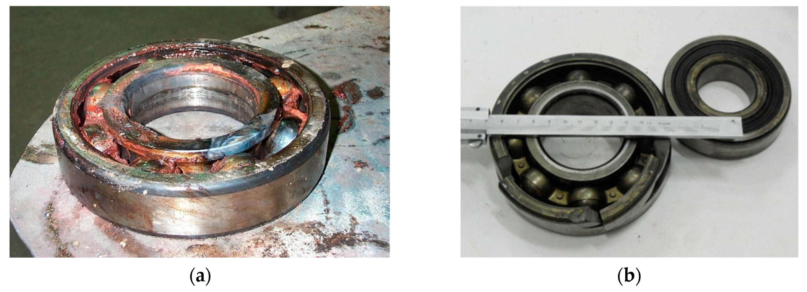
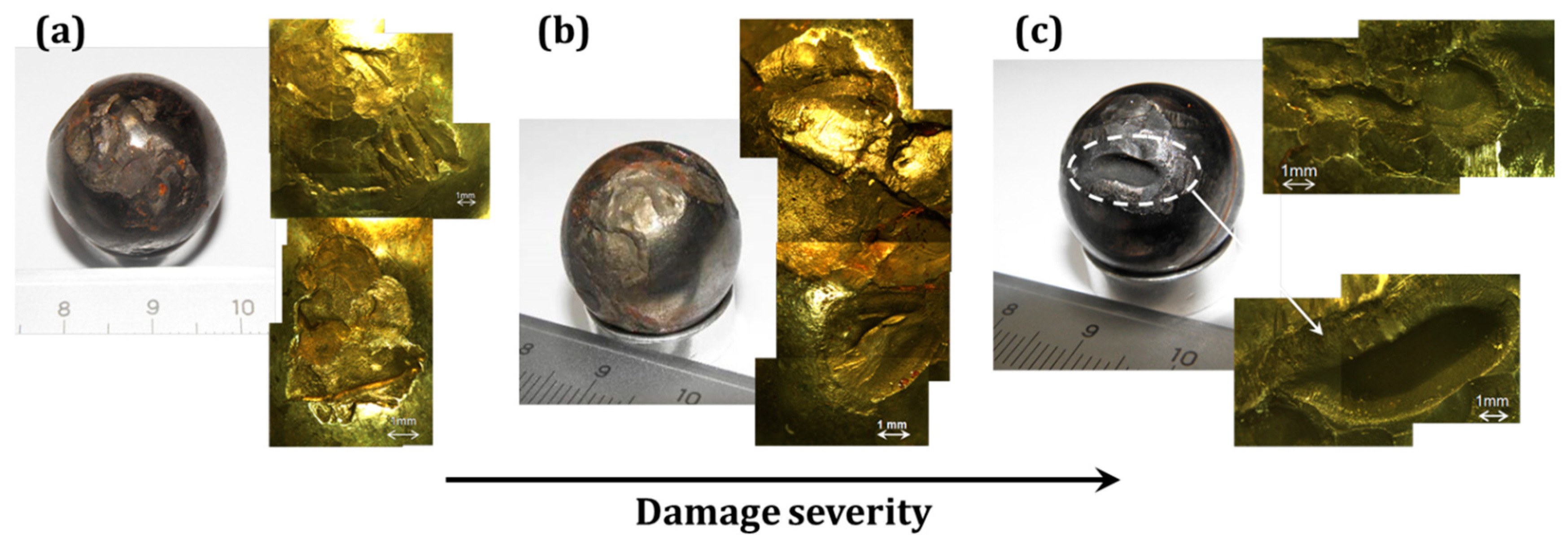
3.2. Catastrophic Failure of Rolling Bearings

The catastrophic failure of a rolling-element bearing that should operate in the hydrodynamic lubrication regime [13] is presented as an example of metal degradation due to failure of the protective means.
The sub-assembly failed after six months of continuous operation in a centrifugal pump that was supporting the recirculation of monoethanolamine (ΜΕA) in a petroleum refinery. Unhampered performance of the assembly is crucial since such a cleaning process of several products is essential before their further treatment; thus, interruption of the pump operation has a negative financial effect on the entire production. The temperature at the cleaning unit did not exceed 45 °C, whilst the speed was 2899 rpm, ~24% lower than the maximum value recommended by the bearing’ s supplier.
After the removal of all the organic residuals from the metallic surface, visual inspection revealed the catastrophic failure of the outer ring of the sub-assembly (Figure 3). In particular, 30% of its periphery was separated into three fragments that presented irregular fracture surfaces (Figure 4) and signs of oxidation on them (Figure 5).
Disassembling of the rolling bearing revealed that failure was not limited to the ring, but it has also affected the rolling elements (balls) that exhibited material removal in the form of craters of smaller or higher dimensions (Figure 6).
The morphology of both the fracture surfaces of the outer ring and the rolling balls advocates for insufficient lubrication during operation that resulted in impact loading that led eventually to the detrimental catastrophic failure of the sub-assembly and the operation interruption of the whole cleaning unit.

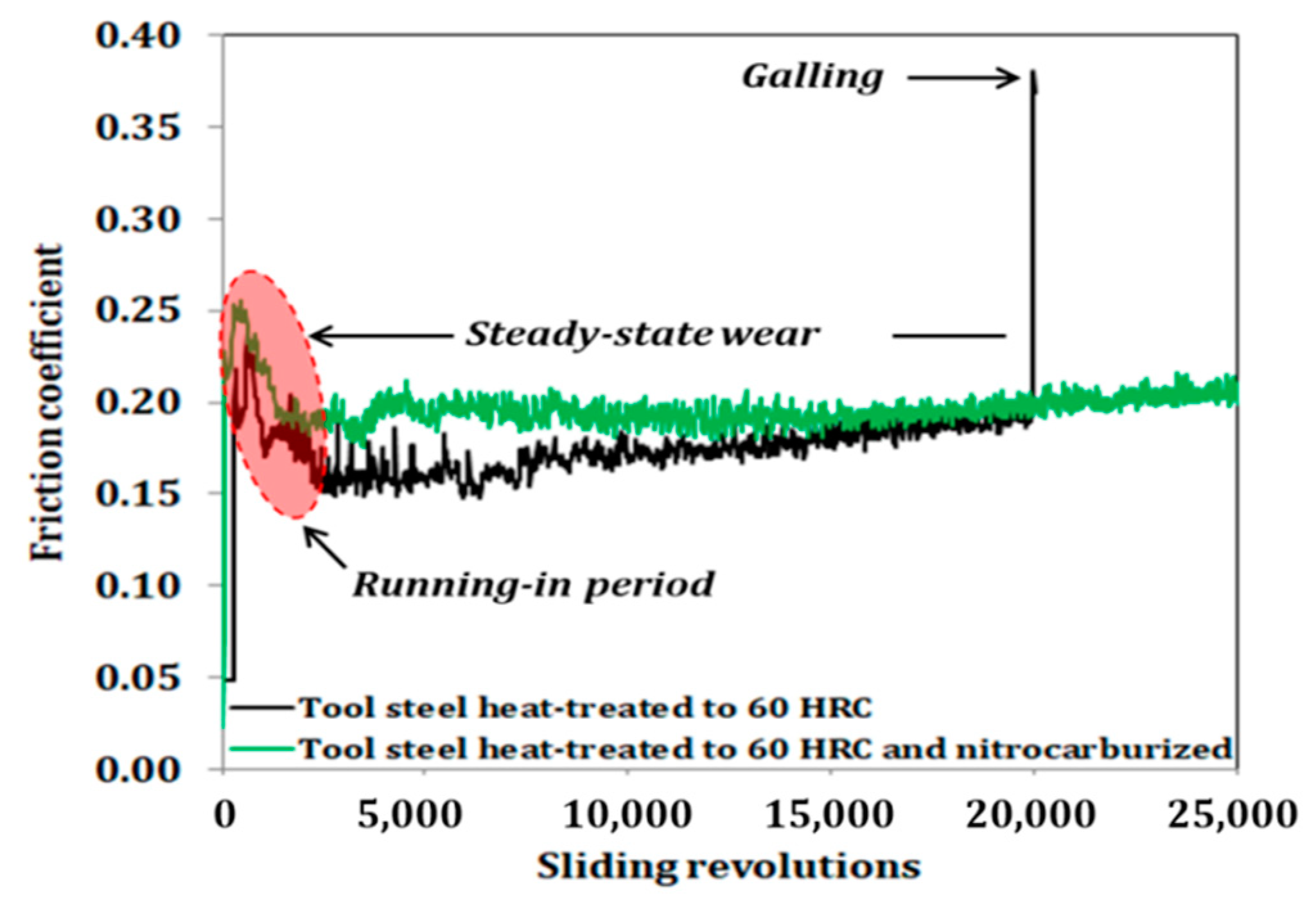
4. Case Study II: Failure of Nitrocarburized Sliding Bearings

4.1. Fundamentals of Nitrocarburizing
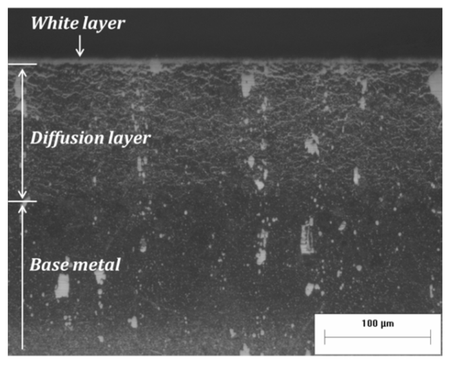
Several engineering components, such as gears and shafts, are commonly manufactured by steel of different grades and hardening degrees, depending on the type and the level of mechanical loading to which they would be subjected during their final application. In the case of these metals serving as parts of a tribosystem, their surface reinforcement against sliding wear is a requirement not only for decreasing their wear rate, but also for altering the wear micro-mechanisms that could lead to the secondary activation of severe degradation of the entire structure via oxidation and/or crack initiation and propagation. Such a surface modification technique widely applied at an industrial scale is nitrocarburizing and, especially, Tufftriding, often referred to as liquid nitrocarburizing.
Tufftriding is a thermochemical technique governed by the diffusion of nitrogen and carbon in the ferrous matrix [5,14,15]. After a first step of preheating for moisture removal, the steel components are immersed for about 6 h in a bath of cyanide salts, with a chemical composition of 60% KCN, 24% KCl, and 16% K2CO3. The treatment temperature remains constant at 580 °C, lower than that of austenitization; thus, the technique is characterized as ferritic nitriding. Under these conditions, two chemical reactions take place:
2KCN + O2 → 2KCNO
8KCNO → 2K2CO3 + 4KCN + CO2 + (C)Fe + (N)Fe
During the first reaction, potassium cyanide is oxidized to potassium oxycyanide, whilst during the second one, atomic nitrogen and carbon are produced and adsorbed by the solid surface. The desirable surface layer, enriched in nitrogen and carbon, is formed via simultaneous chemical reaction of the produced species with the ferrous matrix and nitrogen in-depth diffusion, as described by Fick’ s second law:
C t = D 2 C x 2
After their rinsing with water to remove salt residues mechanically attached to the steel surface, the components are subjected to a stress relief heat treatment.
These two simultaneous mechanisms lead to the consecutive formation of two distinct layers [16,17,18] on the treated surface, that both consist the so-called case depth (Figure 7):
(a)
The outermost one is the product of the chemical reaction between the diffusing atoms and the iron of the base steel and consists mainly of ε-carbonitride Fe2-3 (C,N). This layer, known as white or compound layer, is the feature that provides high wear resistance to the underlying material. Although its thickness does not exceed 10 μm, the compound layer contributes to the decrease of specific wear even by an order of magnitude [17].
(b)
The layer underneath is formed via the in-depth nitrogen diffusion that leads, primarily, to α-(Fe,N) solid solution with a nitrogen content decreasing with increasing depth. In previous works [18], it was found that the thickness of this diffusion layer is strongly affected by the exact chemical composition of the steel grade, its level of prior thermal hardening, or cold working percentage. Although this layer does not affect the wear resistance, it results in a field of compressive stresses that have a positive effect on the fatigue performance of the treated components.
Compared to other gas nitriding techniques, Tufftriding is a widely applied one, mainly due to its low cost, easy application, and high reproducibility. Nowadays, the scientific interest of engineers applying this technique is focused on the waste neutralization and their management optimization strategies, since from a materials point of view, the reliability of the technique is indisputable.

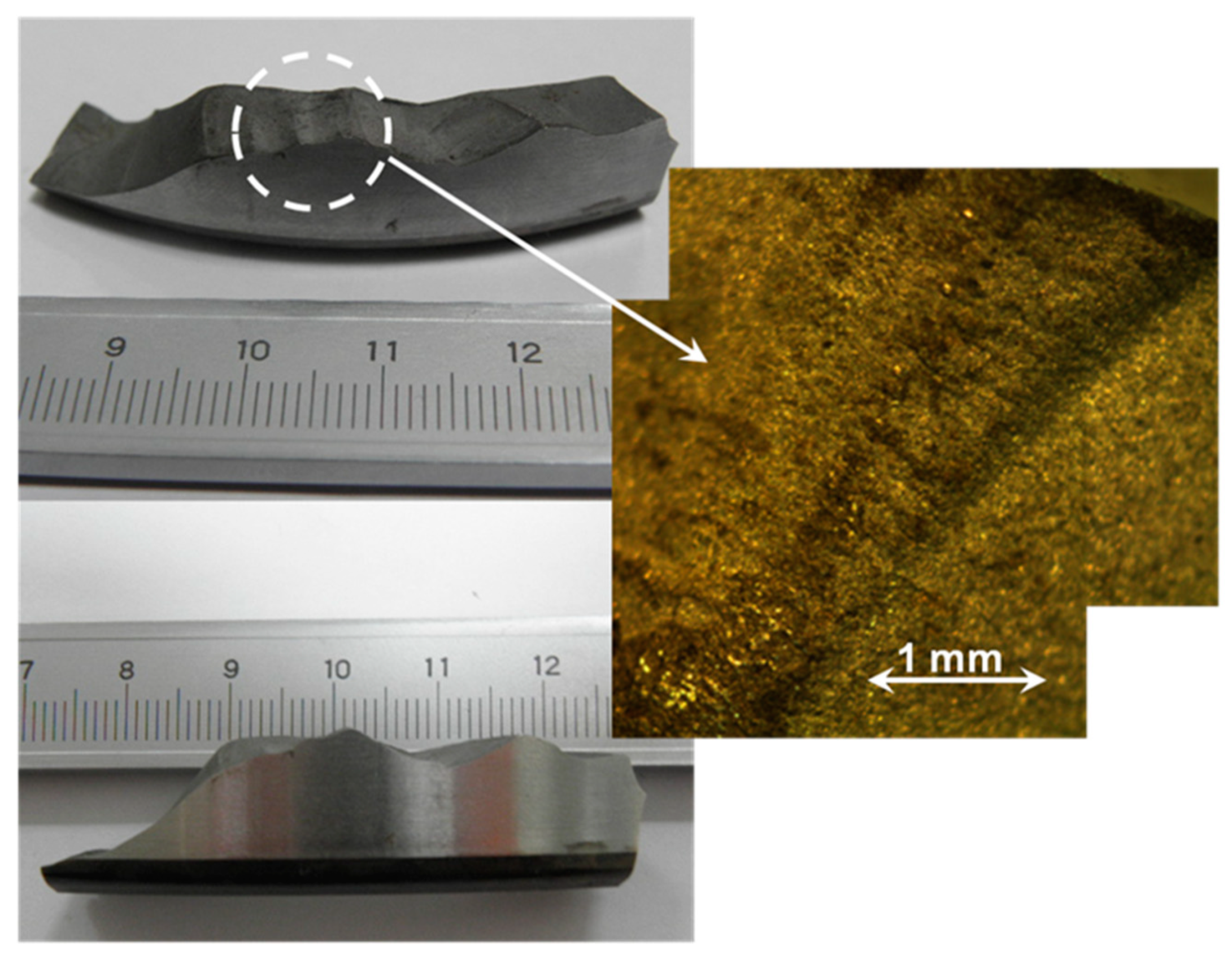
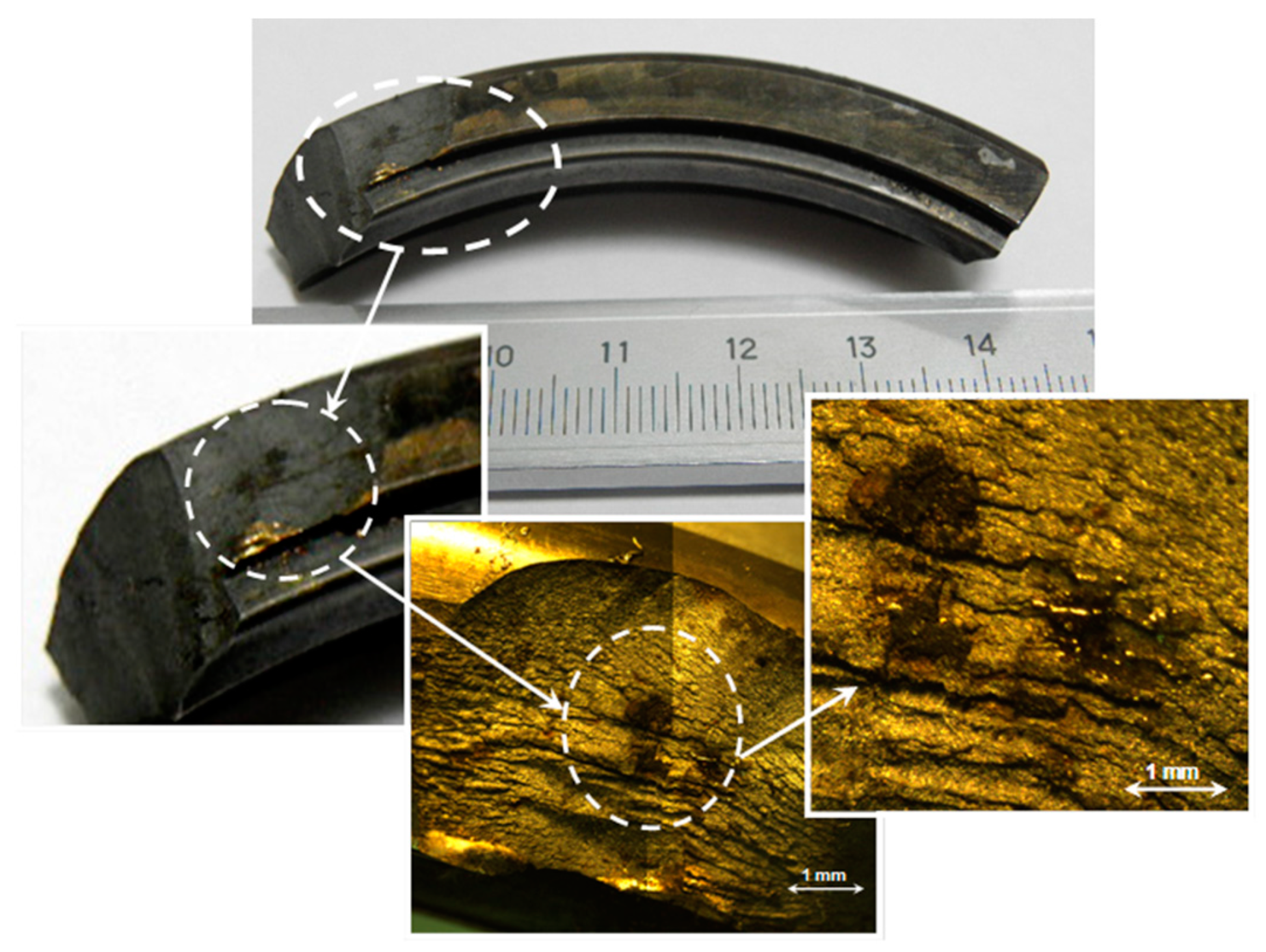
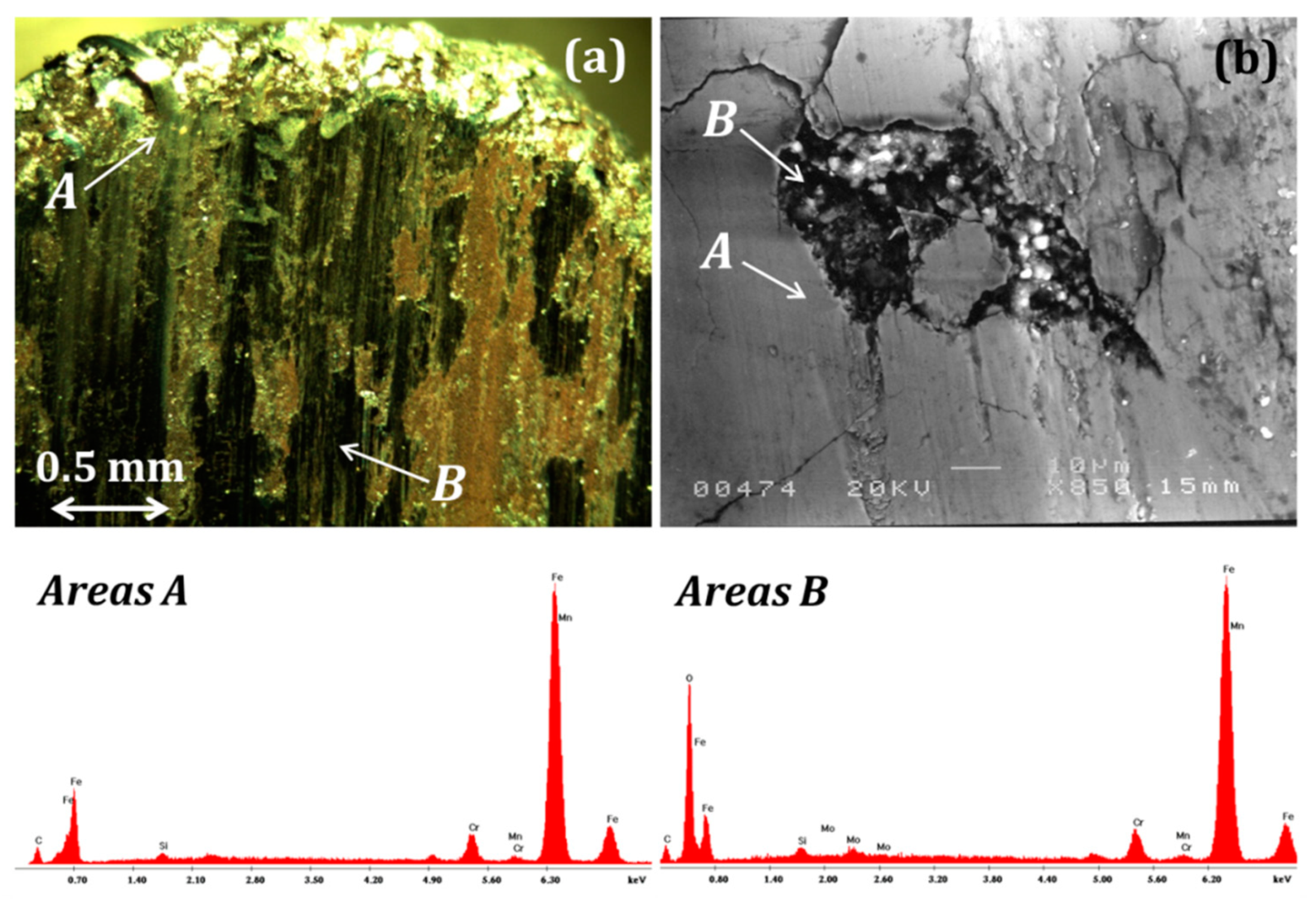
4.2. Degradation of Nitriding Layers and Acceleration of Base Metal Failure

In a previous work [19] concerning the comparative study of the same steel grades with and without surface nitrocarburizing surface treatment, it was demonstrated that Tufftriding prevents galling failure (Figure 8), i.e., motion suspension of a metal–metal tribopair due to strong adhesion phenomena having occurred at the contact surface during dry sliding, typically observed in the case of sliding bearings. Moreover, nitrocarburizing protects the metallic surface from extensive oxidation (Figure 9a) that can lead to secondary tribo-corrosion mechanisms that would increase the wear rate of the metallic component.
However, overloading can lead to cracking and exfoliation of the protective white layer (Figure 9b) creating cavities on the worn surface. In dry sliding under ambient atmosphere, these cavities act as loci of moisture accumulation that promote oxidation of the underlying diffusion zone, leading at the same time to extensive internal oxidation [16]. Even if nitrocarburizing has a positive effect on the dry sliding performance, a designer should take the operational limits (maximum applied load and sliding speed) per steel grade and hardening level into account. In cases of nitrocarburizing of a steel of low hardness, the “quasi-protective” layer would fail under milder operational parameters, accelerating the degradation of the underlying base metal. Since it is rather costly and time-consuming to test experimentally a material before proposing it as the suitable one for a specific application, the development of a well-structured artificial neural network (ANN) can provide wear maps that predict the areas of safe application [20] or areas of wear mechanism alteration [21].

5. Case Study III: Failure of Wear-Resistant Hardfacing Overlayers

5.1. Hardfacing Overlayers Elaborated via Melting and Resolidification

In many applications, the increased resistance to surface loading is often achieved via the deposition of composite layers, consisting of a metallic matrix reinforced by ceramic particulates. The latter are usually oxide or carbide particles that are dispersed homogeneously in the metal. Such overlayers are deposited with a thickness of ~300 μm up to several mm, and they exhibit high hardness and a low wear coefficient. These properties render them ideal protection for surfaces of conjugated elements that operate in tribo-pairs under severe loading in demanding industrial environments, whilst their exact values are defined by both the type of the reinforcing particles as well as their percentage and size distribution.
The common methodology for depositing composite overlays reinforced by carbide particles onto steel base metal is based on the fundamentals of arc welding and is typically applied in filling cavities on metallic surfaces that have been subjected to extreme abrasive wear. In this particular case, the overlayers are referred as “hardfacings”—not simply as “surface coatings”—a term that emphasizes their inherent properties (high hardness, low wear coefficient), beneficial for applications where wear resistance is the prime requirement. In conventional arc welding techniques, the material to be deposited is provided as a consumable bulk rod that contains iron, carbon, and strongly carbide-forming elements. During hardfacing, the feedstock material at its molten state is deposited on the surface of the ferrous base metal, part of which is also subjected to melting. The relevant weight percentage of the material provided and the base metal, when both exist in the liquid state of total miscibility, is called dilution, and its exact value is depended on the particular welding technique used and the operational parameters applied. During cooling, this melt is re-solidified leading to the desirable hard overlayer, the microstructure of which is governed by the chemical composition of the melt [22] and the cooling rate imposed. This processing results in the dispersion of carbides—primarily of the strongly carbide-forming elements contained in the feedstock rod—within a Fe-based matrix, having a modified chemical composition compared to the initial one of the base metal. Typical examples of such a structure are presented in Figure 10.
In a variation of hardfacing via the arc welding technique known as flux core arc welding (FCAW), the carbide powder comprises the core of a tubular metallic-shell rod, which is used as feeding material, so that the carbide particles are introduced in their solid state in the metallic melt and not precipitated thereof as primary carbides during solidification, as previously described. In both cases, the temperature at the vicinity of the metallic pool should exceed 1550 °C, typical of the melting temperature of common steels. Hardfacings deposited via arc welding find wide industrial applications, because of the low cost of the needed facilities and the occupation of non-highly-skilled personnel; however, the elaborated overlayers often exhibit microstructure flaws due to the rather empirical and random way of application. These flaws, commonly pores and cracks (Figure 11), are typical of all processes based on the gradual solidification of melts in contact with non-molten solids, deteriorating the elements’ performance and reducing their service life. Especially in the case of manual deposition, the non-precise control of the treatment parameters increases the possibility of such flaws. Moreover, the occasionally prolonged exposure of the workpieces to high thermal loads results in extended heat-affected zones and could cause distortion of the entire structure and/or detrimental transformations of the base metal microstructure.
Besides conventional arc welding, the plasma transferred arc (PTA) [23,24] and laser beams [25,26] are applied as non-conventional techniques for elaborating hard overlayers on steel components. Nevertheless, the small diameter of the high-energy beam limits the melting area to a diameter lower than 3 mm, a fact that in turn imposes multiple-step processing of larger surfaces, intensifying the negative effects of high thermal loading. Recently, concentrated solar energy (CSE) was proven [27] an attractive alternative for elaborating such hardfacing layers free of pores and cracks on large dimensional surfaces.
In the following paragraph, the case of hardfacing TiC-based overlayers deposited via automated arc melting technique is presented as a good practice example of the development of wear-resistant composite hardfacings.

5.2. Performance of TiC-Based Composite Overlayers Produced via FCAW Technique
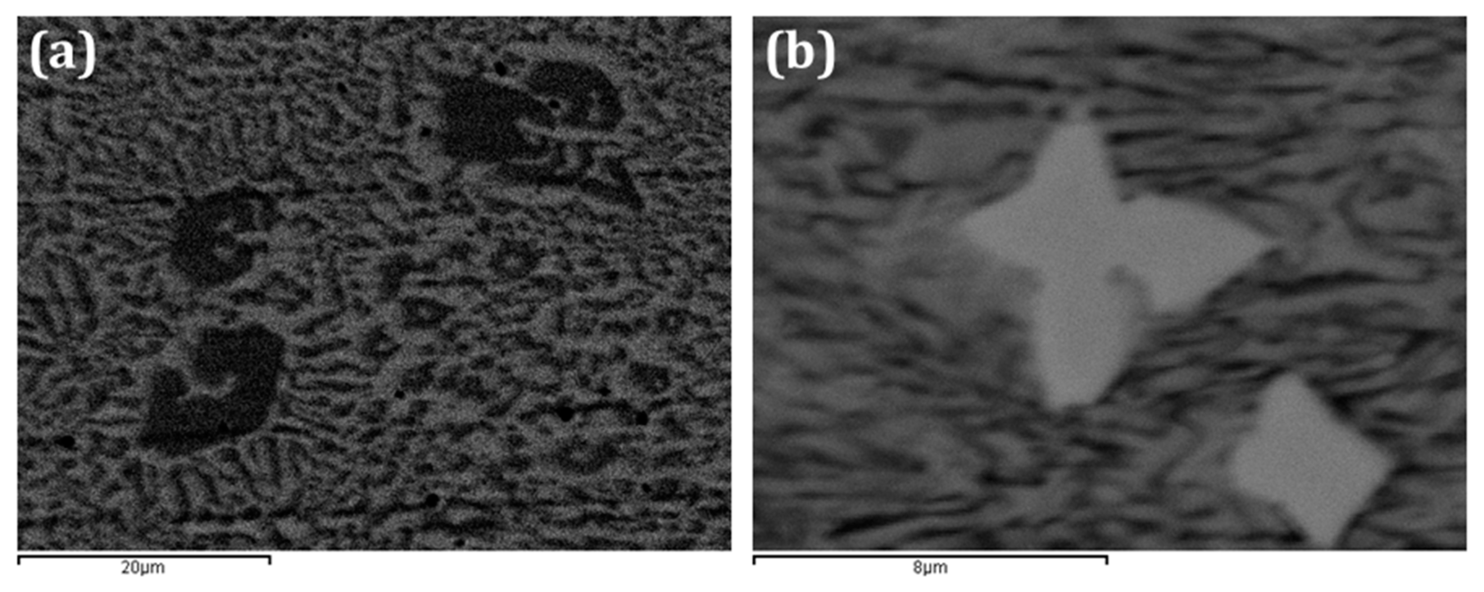
The microstructure characteristics and the XRD analysis of both the core of the commercial wire fed for the elaboration of the conventional FCAW hardfacing, as well as of the deposits obtained are compared in Figure 12. The particles’ agglomerates (Figure 12a) consist of TiC, which is the compound of interest in the present study, and CaF2 and Si, which are the fluxing agents, whilst traces of ferrite were also detected originating from the wire’s shell (Figure 12b). The deposit obtained (Figure 12c) is characterized by the uniform dispersion of fine TiC particulates in the metallic matrix, with rare presence of small size pores, and consists of only ferrite and TiC (Figure 12d).
The tribological in-service performance of these FCAW deposits against an Al2O3 ball is presented in Figure 13. The friction coefficient reached immediately the steady-state stage (Figure 13a), acquiring a constant value of 0.78 ± 0.02, which was practically the same for both applied loads. The wear coefficient reached the steady-state conditions after 20,000 sliding revolutions (Figure 13b), tending towards (5.45 ± 0.31) × 10−7 and (6.84 ± 0.49) × 10−7 mm3 × N−1 × laps−1 for 5 and 10 N, respectively.
SEM observations of the worn surface revealed a wear track of ~840 µm width (Figure 14a), within which polishing lines and oxidation areas of the metallic matrix (Figure 14b) can be clearly observed, together with the emerged fine carbides dispersion (Figure 14c). Compared to the deposits obtained via the novel CSE technique previously mentioned [27], the friction coefficient values, as well as the wear coefficient and the associated micro-mechanisms, exhibit significant differences originating from the size of the reinforcing TiC particles and their dispersion in the matrix:
(a)
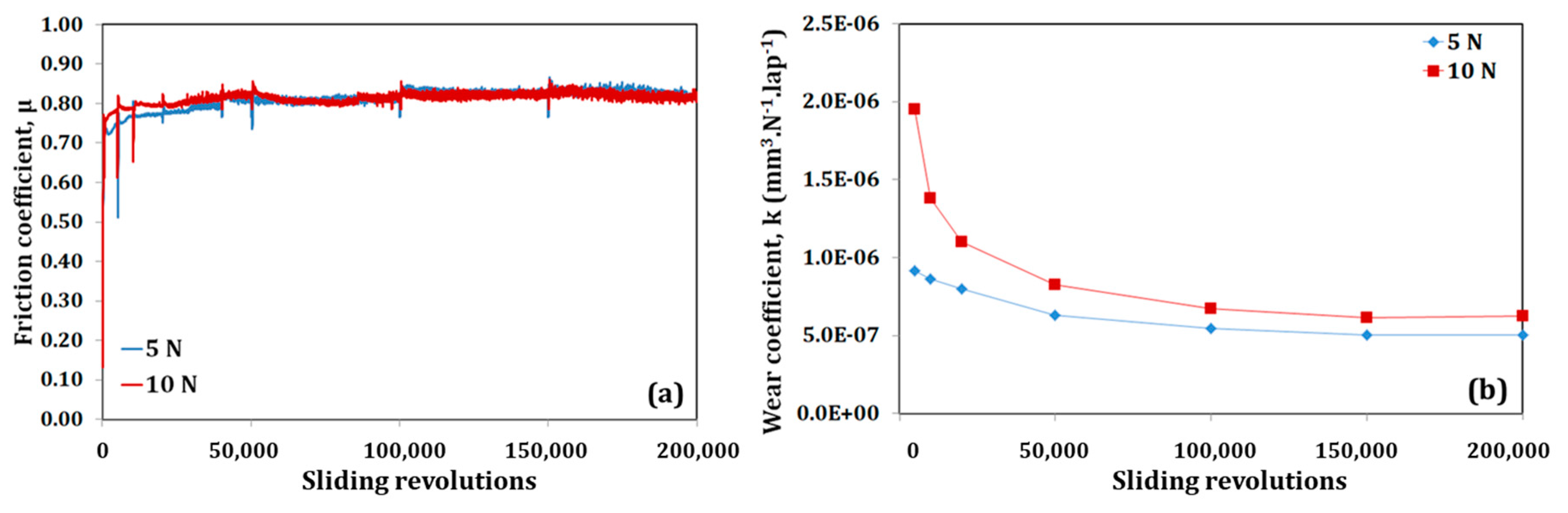
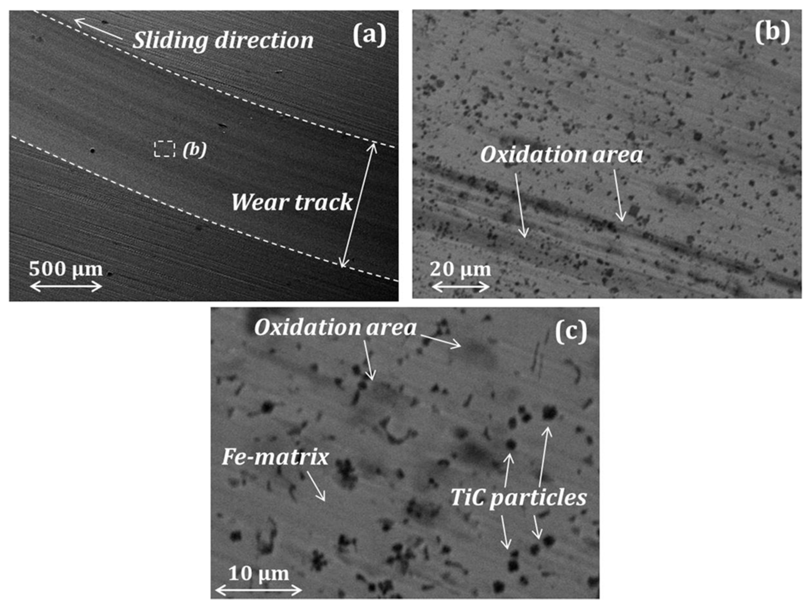
The conventional FCAW deposits, enhanced by TiC particles of finer size, exhibit a rather metallic nature, with high friction coefficient values, tending towards those of a typical tool steel [17] and the relevant wear micro-mechanisms, involving polishing and oxidation of the metallic matrix.
(b)
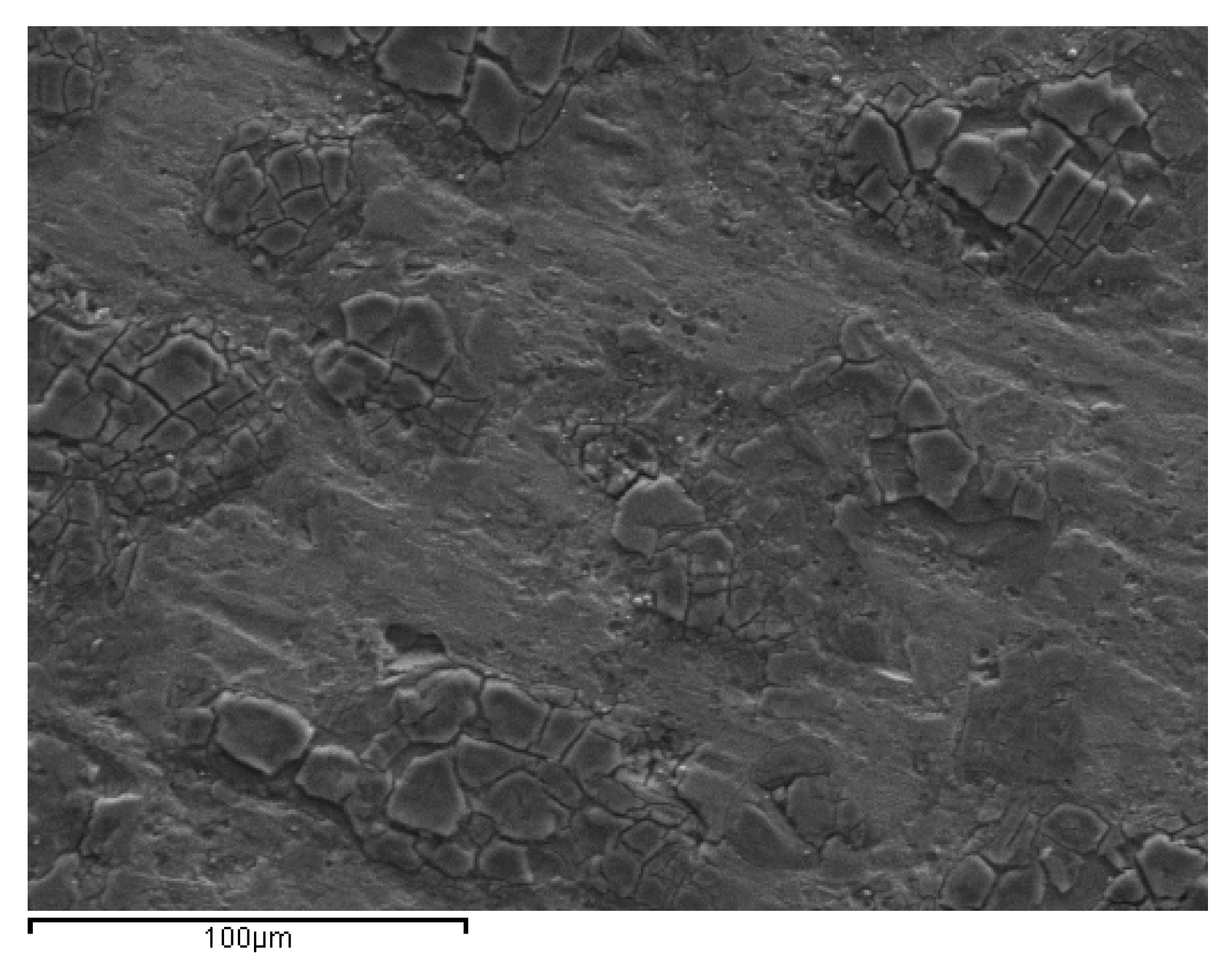
The solar surface layers, enhanced by TiC particles of larger size, exhibit the typical nature of a ceramic-particle-reinforced metal (CPRM) composite, with the ceramic phase playing the predominant role in the low friction coefficient values. The wear micro-mechanism is a clear superposition of the plastic deformation of the metallic matrix and the micro-fragmentation of the carbides, leading finally to exfoliation (Figure 15).
The comparative results of the tribological performance of the FCAW deposits and those concerning non-conventional CSE-obtained hardfacing layers are summarized in Table 3.

6. Case Study IV: Failure of Wear-Resistant Thermal-Sprayed Ceramic Coatings

The last surface modification family of techniques widely applied at an industrial scale for the wear protection of metallic components is thermal spraying [7,28]. Ceramic particles or bulk metallic material in the form of rods are introduced in an area of high temperature, where they are heated even to their melting temperatures and are accelerated toward the surface to be coated. These totally or partially molten particles arriving at the target transmit their thermal and kinetic energy almost instantaneously and are solidified rapidly providing the desirable coating. Nowadays, several thermal spraying techniques are available, each one characterized by the ratio of thermal to kinetic energy attributed to the material to be deposited, the means implemented to create the high temperature area, and the atmosphere surrounding the accelerating particles. Ceramic materials, due to their high tribological performance and their characteristic mechanical resistance to compressive loading [29], also attract interest for their application as protective coatings. Typically, atmospheric plasma spraying (APS) is applied to deposit oxide layers [30,31], whilst the high-velocity oxyfuel (HVOF) technique is used to form carbide [32,33] wear-resistant layers.
Due to the peculiarities of the deposition technique, ceramic plasma-sprayed coatings, having a thickness of 200–400 µm, exhibit stratified structure with interfacial roughness, which promotes the formation of porosity (Figure 16a) and mechanical anchorage to the metallic surface. In order to enhance the latter prior to thermal spraying, it is necessary to prepare the metallic solid via sandblasting. This pre-processing could result in sand residues (Figure 16b) on the surface leading to poor adhesion to the metallic substrate. In particular in the case of carbide coatings, their deposition under non-recommended parameters of spraying technique causes their in-flight decomposition/decarburization [34,35,36,37,38,39].
Despite all the above microstructure flaws possibly present in a thermal-sprayed coating, their tribological performance could be acceptable when operating under mild conditions [40]. Under more severe service conditions, these structure flaws accelerate their degradation (Figure 17a) via vertical cracking (Figure 17b), providing the route to the moisture or corrosive gases, to penetrate until the metallic surface that would be hence oxidized.

7. Epilogue

In general, the operation of metallic parts and components as elements of a tribosystem requires their further surface enhancement. Several techniques are available for facilitating relevant motion of two solids in contact, which is reflected in low friction coefficient values, and/or for prolonging their lifetime by using surface layers of lower wear rates. In this review, four cases of common wear protective techniques were presented in order to emphasize that the wrong application of the “quasi-protective” layer on the contact surfaces does not prevent but rather accelerate the degradation of the metallic component.
When using an oil lubricant, a strict schedule of periodic inspection of the sum-assembly should be followed in parallel to the periodic oil drain (oil discharge), while its selection should be made taking into account the compatibility of the lubricant’ s additives to the metal of the solid.
In the case of implemented diffusion coatings, as the nitrocarburized ones, the bulk hardness of the protected component should be carefully selected, since it affects the good performance of the wear-resistant white layer.
In the case of hardfacing overlayers elaborated via arc welding techniques, the formation of structure flaws associated to solidification of liquid metals (pores and cracks) could be prevented by the proper selection of processing parameters and, if possible, of an automated technique.
Finally, in the case of thermal-sprayed ceramic coatings the selection of the proper technique is of crucial importance to avoid structural flaws that eventually lead to the rapid degradation of the underlying metallic part.

Funding

This research received no external funding.

Acknowledgments

The author would like to thank all the under-graduate and post-graduate students as well as the Ph.D. candidates having carried/carrying out their theses in the Tribology Laboratory of our Department; their work allowed collecting the experimental knowledge briefly presented in this review article.

Conflicts of Interest

The author declares no conflict of interest.

References

  1. Williams, J.A. Engineering Tribology, 1st ed.; Oxford University Press Inc.: New York, NY, USA, 1994. [Google Scholar]
  2. Friction, Lubrication and Wear Technology; ASM Handbook; ASM International: Materials Park, OH, USA, 1992; Volume 18.
  3. Zum Gahr, K.-H. Microstructure and Wear of Materials, 1st ed.; Elsevier: Amsterdam, The Netherlands, 1987. [Google Scholar]
  4. Holmberg, K.; Matthews, A. Coatings Tribology, 1st ed.; Elsevier: Amsterdam, The Netherlands, 1994. [Google Scholar]
  5. Heat Treating; ASM Handbook; ASM International: Materials Park, OH, USA, 1991; Volume 4.
  6. Surface Engineering; ASM Handbook; ASM International: Materials Park, OH, USA, 1994; Volume 5.
  7. Fauchais, P.L.; Heberlein, J.V.R.; Boulos, M.I. Thermal Stray Fundamentals: From Power to Part, 1st ed.; Springer: New York, NY, USA, 2014. [Google Scholar]
  8. Stribeck, R. Die Wesentlichen Eigenschaften der Gleit-und Rollenlager. Z. Ver. Deul. Zng. 1902, 46, 180. [Google Scholar]
  9. Avitzur, B. Boundary and hydrodynamic lubrication. Wear 1990, 139, 49–76. [Google Scholar] [CrossRef]
  10. Avitzur, B. Modelling the effect of lubrication on friction behavior. Lubr. Sci. 1990, 2, 99–132. [Google Scholar] [CrossRef]
  11. Vrčeka, A.; Hultqvista, T.; Baubetb, Y.; Marklunda, P.; Larssona, R. Micro-pitting damage of bearing steel surfaces under mixed lubrication conditions: Effects of roughness, hardness and ZDDP additive. Tribol. Int. 2019, 138, 239–249. [Google Scholar] [CrossRef]
  12. Ancellotti, S.; Fontanari, V.; Dallago, M.; Benedetti, M. A novel experimental procedure to reproduce the load history at the crack tip produced by lubricated rolling sliding contact fatigue. Eng. Fract. Mech. 2018, 192, 129–147. [Google Scholar] [CrossRef]
  13. Stolarski, T.A.; Tobe, S. Rolling Contacts, 1st ed.; John Wiley & Sons, Ltd.: Hoboken, NJ, USA, 2000. [Google Scholar]
  14. Pye, D. Practical Nitriding and Ferritic Nitrocarburizing; ASM International: Materials Park, OH, USA, 2005. [Google Scholar]
  15. Pantazopoulos, G.A. Tufftriding and Tennifer Surface Treatment. In Encyclopedia of Tribology; Wang, Q.J., Chung, Y.W., Eds.; Springer: Boston, MA, USA, 2013. [Google Scholar]
  16. Psyllaki, P.; Kefalonikas, G.; Pantazopoulos, G.; Sideris, J.; Antoniou, S. Microstructure and tribological behaviour of liquid nitrocarburized tool steels. Surf. Coat. Tech. 2002, 162, 67–78. [Google Scholar] [CrossRef]
  17. Karamboiki, C.-M.; Mourlas, A.; Psyllaki, P.; Sideris, J. Influence of microstructure on the sliding wear behavior of nitrocarburized tool steels. Wear 2013, 303, 560–568. [Google Scholar] [CrossRef]
  18. Pantazopoulos, G.; Psyllaki, P. An overview on the tribological behaviour of nitro-carburised steels for various industrial applications. Tribol. Ind. 2015, 37, 299–308. [Google Scholar]
  19. Psyllaki, P.; Stamatiou, K.; Iliadis, I.; Mourlas, A.; Asteris, P.; Vaxevanidis, N. Surface treatment of tool steels against galling failure. MATEC 2018, 188, 04024. [Google Scholar] [CrossRef]
  20. Cavaleri, L.; Asteris, P.G.; Psyllaki, P.P.; Douvika, M.G.; Skentou, A.D.; Vaxevanidis, N.M. Prediction of surface treatment effects on the tribological performance of tool steels using artificial neural networks. Appl. Sci. 2019, 9, 2788. [Google Scholar] [CrossRef]
  21. Rasool, G.; Stack, M.M. Wear maps for TiC composite based coatings deposited on 303 stainless steel. Tribol. Int. 2014, 74, 93–102. [Google Scholar] [CrossRef] [Green Version]
  22. Chaidemenopoulos, N.; Psyllaki, P.; Pavlidou, E.; Vourlias, G. Aspects on carbides transformations of Fe-based hardfacing deposits. Surf. Coat. Tech. 2019, 357, 651–661. [Google Scholar] [CrossRef]
  23. Bourithis, L.; Papaefthymiou, S.; Papadimitriou, G.D. Plasma transferred arc boriding of a low carbon steel: Microstructure and wear properties. Appl. Surf. Sci. 2002, 200, 203–218. [Google Scholar] [CrossRef]
  24. Bourithis, L.; Papadimitriou, G.D. The effect of microstructure and wear conditions on the wear resistance of steel metal matrix composites fabricated with PTA alloying technique. Wear 2009, 266, 1155–1164. [Google Scholar] [CrossRef]
  25. Pantelis, D.; Tissandier, A.; Manolatos, P.; Ponthiaux, P. Formation of wear resistant Al-SiC composite by laser melt-particle injection process. Mater. Sci. Tech. 1995, 11, 299–303. [Google Scholar] [CrossRef]
  26. Pantelis, D.; Michaud, H.; de Freitas, M. Wear behaviour of laser surface hardfaced steels with tungsten carbide powder injection. Surf. Coat. Tech. 1993, 57, 123–131. [Google Scholar] [CrossRef]
  27. Mourlas, A.; Pavlidou, E.; Vourlias, G.; Rodríguez, J.; Psyllaki, P. Concentrated solar energy for in-situ elaboration of wear-resistant composite layers. Part I: TiC and chromium carbide surface enrichment of common steels. Surf. Coat. Tech. 2019, 377, 124882. [Google Scholar] [CrossRef]
  28. Aranke, O.; Algenaid, W.; Awe, S.; Joshi, S. Coatings for automotive gray cast iron brake discs: A review. Coatings 2019, 9, 552. [Google Scholar] [CrossRef]
  29. Basu, B.; Kalin, M. Tribology of Ceramics and Composites, 1st ed.; John Wiley & Sons Inc.: Hoboken, NJ, USA, 2011. [Google Scholar]
  30. Pantelis, D.; Psyllaki, P.; Alexopoulos, N. Tribological behaviour of plasma-sprayed Al2O3 coatings under severe wear conditions. Wear 2000, 237, 197–204. [Google Scholar] [CrossRef]
  31. Psyllaki, P.; Jeandin, M.; Pantelis, D. Microstructure and wear mechanisms of thermal-sprayed alumina coatings. Mater. Lett. 2001, 47, 77–82. [Google Scholar] [CrossRef]
  32. Kekes, D.; Psyllaki, P.; Vardavoulias, M.; Vekinis, G. Wear micro-mechanisms of composite WC-Co/Cr-NiCrFeBSiC coatings. Part II: Cavitation erosion. Tribol. Ind. 2014, 36, 375–383. [Google Scholar]
  33. Kekes, D.; Psyllaki, P.; Vardavoulias, M. Wear micro-mechanisms of composite WC-Co/Cr-NiCrFeBSiC coatings. Part I: Dry sliding. Tribol. Ind. 2014, 36, 361–374. [Google Scholar]
  34. Verdon, C.; Karimi, A.; Martin, J.-L. A study of high velocity oxy-fuel thermally sprayed tungsten carbide based coatings. Part 1: Microstructures. Mat. Sci. Eng. A Struct. 1998, 246, 11–24. [Google Scholar] [CrossRef]
  35. Liao, H.; Normand, B.; Coddet, C. Influence of coating microstructure on the abrasive wear resistance of WC/Co cermet coatings. Surf. Coat. Tech. 2000, 124, 235–242. [Google Scholar] [CrossRef]
  36. Sahraoui, T.; Fenineche, N.-E.; Montavon, G.; Coddet, C. Structure and wear behaviour of HVOF sprayed Cr3C2-NiCr and WC-Co coatings. Mater. Des. 2003, 24, 309–313. [Google Scholar] [CrossRef]
  37. Morks, M.F.; Gao, Y.; Fahim, N.F.; Yingqing, F.U.; Shoeib, M.A. Influence of binder materials on the properties of low power plasma sprayed cermet coatings. Surf. Coat. Tech. 2005, 199, 66–71. [Google Scholar] [CrossRef]
  38. Lee, C.W.; Han, J.H.; Yoon, J.; Shin, M.C.; Kwun, S.I. A study on powder mixing for high fracture toughness and wear resistance of WC-Co-Cr coatings sprayed by HVOF. Surf. Coat. Tech. 2010, 204, 2223–2229. [Google Scholar] [CrossRef]
  39. Venter, A.M.; Oladijo, O.P.; Luzin, V.; Cornish, L.A.; Sacks, N. Performance characterization of metallic substrates coated by HVOF WC-Co. Thin Solid Films 2013, 549, 330–339. [Google Scholar] [CrossRef]
  40. Psyllaki, P.; Mourlas, A.; Vourlias, G.; Pavlidou, E.; Vardavoulias, M. Influence of microstructure flaws on the tribological performance of Cr-based thermal-sprayed ceramic coatings. Ceram. Int. 2019, 45, 19360–19369. [Google Scholar] [CrossRef]
Figure 1. (a) Schematic representation of a tribosystem and (b) magnification of the inter-surface area marked in (a).
Metals 09 01057 g001
Figure 2. Typical Stribeck curve for liquid lubrication and associated regimes.
Metals 09 01057 g002
Figure 3. Rolling bearing as-received (a) and after the removal of organic residuals (b).
Metals 09 01057 g003
Figure 4. Stereoscopic images of a fragment of the failed outer ring, exhibiting geometric irregularities.
Metals 09 01057 g004
Figure 5. Stereoscopic images of a fragment of the failed outer ring, exhibiting signs of oxidation on the fracture surface.
Metals 09 01057 g005
Figure 6. Representative failed rolling balls exhibiting different levels of damage severity.
Metals 09 01057 g006
Figure 7. Representative cross-section of a tool steel subjected to Tufftriding (optical micrograph).
Metals 09 01057 g007
Figure 8. Evolution of the friction coefficient of a tool steel grade with and without nitrocarburizing surface treatment.
Metals 09 01057 g008
Figure 9. Scanning electron microscopy (SEM) micrographs and EDS point analysis on characteristic areas of the worn surfaces before surface treatment (a) and after liquid nitrocarburizing (b).
Metals 09 01057 g009
Figure 10. SEM micrographs of primary (a) chromium and (b) niobium carbides formed on an AISI 4130 steel via arc welding technique.
Metals 09 01057 g010
Figure 11. Microstructure flaws in hardfacing overlayers deposited manually via arc welding technique: (a) stereoscopic image of top view, revealing the development of surface pores and cracks; (b) optical image of a cross-section, revealing the existence of a sub-surface isolated macro-pore; and (c) SEM image of a cross-section at the vicinity of the base metal, indicating the development within the overlayer of a crack parallel to the interface.
Metals 09 01057 g011
Figure 12. (a) SEM micrograph and (b) X-ray diffraction (XRD) spectrum, respectively, of the core powder of the wire used for flux core arc welding (FCAW) deposits. (c) SEM micrograph and (d) XRD spectrum, respectively, of the obtained hardfacing layers.
Metals 09 01057 g012
Figure 13. Representative ball-on-disk testing results of the FCWA hardfacing layers (counterbody: Al2O3 ball): evolution of (a) friction coefficient and (b) wear coefficient vs. sliding revolutions.
Metals 09 01057 g013
Figure 14. Top view SEM micrographs of the worn surface of the FCAW hardfacing layers, after ball-on-disk testing for 200,000 sliding revolutions, applying a normal load of 10 N: (a) entire width of the wear track, (b) and (c) successive magnifications within the wear track, demonstrating extensive oxidation and abrasion scars along the sliding direction.
Metals 09 01057 g014
Figure 15. Top view SEM micrographs of the worn surface of the “solar” hardfacing layers, after ball-on-disk testing for 200,000 sliding revolutions, applying a normal load of 10 N.
Metals 09 01057 g015
Figure 16. Microstructure flaws developed during plasma spray deposition of (a) a titania coating (optical micrograph), where a longitudinal crack propagated parallel to the coating/substrate interface and (b) a WC-Co coating (SEM micrograph) of poor adhesion to the metallic substrate, due to the presence of residues of the pre-deposition sandblasting preparation of the metallic surface.
Metals 09 01057 g016
Figure 17. Degradation of a composite plasma-sprayed coating: (a) after tribological service a through-depth crack was developed below the contact area and (b) propagated through the carbide reinforcing particles resulting in their multi-rupture.
Metals 09 01057 g017
Table 1. Main categories of lubrication and representative examples.
CategoryRepresentative LubricantsMain Applications
Solid-State LubricationGraphite; Phyllomorphous MineralsDies and Molds for Metal Forming and Shaping
Liquid-State LubricationOil-Based; Water-BasedEngines and Tool-Machines for Metals Machining
Gas-State LubricationAirDental Equipment
Table 2. Main categories of coatings techniques and representative examples.
TechniqueRepresentative Wear-Resistant Surface LayersMain Applications
Thermochemical TreatmentsNitriding and nitrocarburizingForming, Cutting tools, Dies, Gears, Shafts, Clutches
Welding; High-power laserCarbide-reinforced Fe-based compositesHeavily-loaded surfaces
Thermal SprayingOxides (Al2O3; TiO2, YSZ);
WC-, Cr3C2 based CerMets
Medical implants
Heavily-loaded surfaces
Physical or Chemical Vapor Deposition (PVD or CVD)TiN; TiC; BN; Diamond; DLCCutting tools
Metallization/PlatingCr-, Ni- coatingsAutomotive parts
Table 3. Ball-on-disk tribological performance of conventional FCAW deposits, compared to CSE overlayers [27].
Applied LoadFriction Coefficient, µWear Coefficient, k (mm−3.N−1.laps−1)
FCAW DepositsCSE OverlayersFCAW DepositsCSE Overlayers
5 N0.78 ± 0.020.43 ± 0.02(5.45 ± 0.31) × 10-7(3.26 ± 0.41) × 10-7
10 N0.78 ± 0.020.46 ± 0.02(6.84 ± 0.49) × 10-7(4.18 ± 0.42) × 10-7

