Abstract
A strain gradient was produced in an AZ31B magnesium alloy through a plastic deformation of pure torsion at a torsional speed of π/2 per second. Compared with the base material and with the alloy processed by conventional severe plastic deformation, the magnesium alloy provided with a strain gradient possesses high strength preserving its ductility. Microstructural observations show that strain gradient induces the formation of an inhomogeneous microstructure characterized by statistically stored dislocation (SSD) density gradient and geometrically necessary dislocation (GND). GNDs and dislocation density gradient provide extra strain hardening property, which contributes to the improvement of ductility. The combination of SSD density gradient and GND can simultaneously improve the strength and ductility of magnesium alloy.
1. Introduction
Magnesium alloys are a product in great demand in the automotive field due to their high strength-to-weight ratio [1,2]. The poor ductility limits the room temperature formability of magnesium alloys and the relatively low strength leads to the large dimension structure. Magnesium alloys with high strength and high ductility can be in demand in engineering. High strength can be achieved in magnesium alloys by means of well-known methods, e.g., grain refinement [3], element addition [4,5], and work hardening [6]. Due to the insufficient number of operative slips in hexagonal close packed (HCP) crystal structure [7], improving the strength usually accompanies with the poor ductility in magnesium alloys. Strength and ductility are contradictory in magnesium alloys. Trading off the strength and ductility of magnesium alloys is a promising research direction in materials science.
Severe plastic deformation (SPD) has been proved to be an effective method for improving the mechanical properties of magnesium alloys [8,9,10]. Equal channel angular pressing (ECAP) [11], high pressure torsion (HPT) [12], and accumulative roll bonding (ARB) [13] are widely employed SPD techniques. Ultrafine-grained magnesium alloys ZK60 and AZ31 were respectively produced by one-step ECAP and two-step ECAP [14,15]. Superplastic ductility at the temperature of 473 K was achieved in magnesium alloy by means of HPT [16]. ARB was used to process magnesium alloy AZ31 with the mean grain size of 3 μm [17]. Magnesium alloys with a bimodal grain size distribution were obtained by SPD [18,19]. A modified ECAP called C-shape ECAP was developed to improve the hardness of AZ31 [20]. Another modified ECAP combining ECAP and twist extrusion was developed to improve the strength and elongation of magnesium alloys AZ61 [21]. Magnesium alloy AZ91 with high mechanical properties was processed by ECAP and subsequent low temperature rolling [22]. The strength and fatigue performance benefit strongly in magnesium alloy ZX40 by warm ECAP and subsequent room temperature rotary swaging [23]. Recently, inhomogeneous microstructures were introduced into magnesium alloys to improve their mechanical properties. Nanoparticle addition was used to change the recrystallization behavior during extrusion, which improves the strength of magnesium alloy [24]. Combining machining and extrusion, Tekumalla et al. strengthened magnesium alloy AZ91 without compromising ductility by producing fine-grained structures and SPDed grains [25].
The former works focus on the effect of uniform prior plastic strain on the mechanical properties of magnesium alloys. However, this study shows that prior plastic strain gradient can result in gradient hierarchical microstructure in steel [26]. The gradient microstructures inspire us to investigate the role of strain gradient in improving the mechanical properties of magnesium alloys. Here, magnesium alloy AZ31B was respectively processed by ECAP without strain gradient and pure torsion with strain gradient. Compressive tests were conducted to illustrate the difference of mechanical property between AZ31B with strain gradient and without strain gradient. Microstructural characterizations and theoretical models were employed to reveal the effect of the strain gradient on the mechanical properties.
2. Materials and Methods
An AZ31B magnesium alloy bar with the diameter of 4.8 mm was used. The bar whose chemical composition is shown in Table 1 was annealed at the temperature of 618 K for 60 min to obtain a homogeneous coarse grain (CG) microstructure. To reveal the microstructure of the base material, the bar was mechanically polished and then etched in a 5 g picric acid + 10 mL water + 10 mL acetic acid + 100 mL ethanol solution for ~10 s. The etched surface was observed by the optical microscope (Olympus BX51M, Tokyo, Japan). Figure 1 shows the initial microstructure and grain size distribution of the base material. The mean grain size of initial workpiece is ~50 µm.

Table 1.
Chemical composition of magnesium alloy AZ31B.
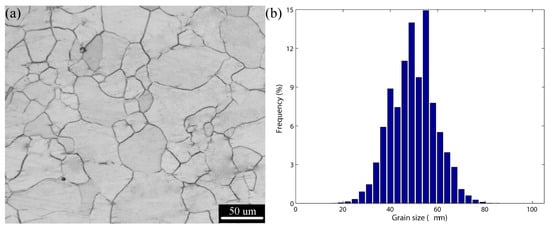
Figure 1.
(a) Initial microstructure of AZ31B; (b) grain size distribution of initial AZ31B.
The initial AZ31B bar was deformed by using two types of deformation mode. Figure 2 shows the schematics of the two deformation modes. In Figure 2a, the initial AZ31B bar was processed by means of equal channel angular pressing (ECAP) where the inner angular Φ is and the outer angular is . Using the strain estimation Equation [11], the effective plastic strain of 0.6 was imposed in workpiece after one pass of ECAP. In Figure 2b, the initial AZ31B with the length of 150 mm was torqued by the radian of . The effective plastic strain is calculated by , where is the distance departing from the center of bar. Figure 2b illustrates the effective plastic strain distribution in the cross-section. The strain gradient during torsion is 1/m.
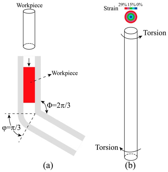
Figure 2.
Schematics of two deformation modes: (a) equal channel angular pressing (ECAP); (b) pure torsion.
The initial workpiece, the specimen processed by ECAP, and the sample after torsion were tested by using material test system. All samples were prepared with a gauge length of 9 mm and a diameter of 4.5 mm. Each test was repeated at least three times for statistical analysis. Quasi-static compressive tests were conducted on Instron E10000 (ITW, Boston, MA, USA) with a strain rate of . The stress strain curves were recorded at the frequency of 10 Hz until the samples fractured. In order to reveal the effect of strain gradient on the microstructural evolution, transmission electron microscope (TEM) observation was carried out on JEM 2010 (JEOL, Tokyo, Japan) with the operating voltage of 200 kV. The samples for TEM were polished down to ~70 μm. To get thin area, the solution of 30 mL nitric acid and 70 mL alcohol was employed at the current of 130 mA and the temperature of 243–253 K. Along the radius direction, three zones were chosen for TEM observation, i.e., the center of bar, the middle zone and the outer zone. The corresponding selected area electron diffraction (SAED) pattern was obtained during TEM observation. Based on the TEM images, the dislocation density of the observed region was measured by means of image analysis technology. The detailed descriptions on the measurement of dislocation density are given in Appendix A.
3. Results
3.1. Mechanical Property
Figure 3 shows stress-strain curves of AZ31B under compressive loading. The 0.2% yield strength of AZ31B processed by ECAP or pure torsion is higher than that of initial workpiece. The ductility of AZ31B processed by ECAP is less than that processed by pure torsion. Compared with the initial workpiece, AZ31B processed by pure torsion possesses higher yield strength but no sacrifice of ductility. The comparisons of mechanical properties are shown in Figure 4. The 0.2% yield strength, ultimate strength and fracture strain of initial workpiece are respectively 105 MPa, 433 MPa and 15.5%. For AZ31B processed by ECAP, yield strength increases by 72.4%, but ultimate strength and fracture strain respectively decrease by 6.7% and 35.5%. As for AZ31B processed by pure torsion, yield strength increases by 71.4%, but ultimate strength and fracture strain are nearly the same as those of initial workpiece.
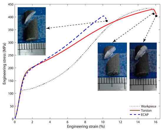
Figure 3.
Engineering stress vs. engineering strain curves for AZ31B processed by different deformation modes (the fractured samples shown at the end of stress-strain curves).
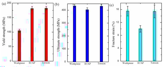
Figure 4.
Comparisons of mechanical properties of AZ31B processed by different deformation modes: (a) yield strength; (b) ultimate strength; (c) fracture strain.
3.2. Microstructural Observation
The bright-field TEM images of AZ31B are illustrated in Figure 5, Figure 6, Figure 7 and Figure 8. As shown in Figure 5, few dislocations appear in initial workpiece. There is no distinct difference for TEM images at position b, c and d in Figure 5. After ECAP, severe plastic deformation was imposed on AZ31B. Statistically stored dislocations (SSDs) resulting from plastic strain accumulate in AZ31B. SSDs are observed in Figure 6b–d. Due to the homogeneous shear deformation during ECAP [11], dislocation densities are the same in different regions. High density dislocations are visible at positions b–d. There is no gradient of dislocation density in AZ31B after ECAP. The microstructures in Figure 6 were characterized by high density dislocations and sub-boundaries. These dislocations were blocked and piled up at sub-boundaries, contributing to the strengthening. This clearly explains the improvement of 0.2% yield strength in AZ31B after ECAP (Figure 3).
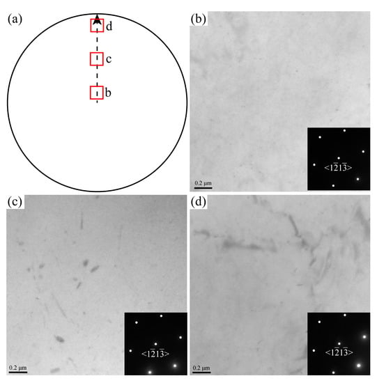
Figure 5.
TEM observation of AZ31B initial workpiece along a direction: (a) schematic of the three observed positions; (b) center of bar; (c) middle zone; (d) outer zone.
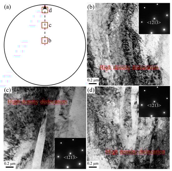
Figure 6.
TEM observation of AZ31B processed by ECAP along a direction: (a) schematic of three observation positions; (b) center of bar; (c) middle zone; (d) outer zone.
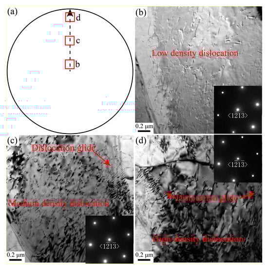
Figure 7.
TEM observation of AZ31B processed by pure torsion along a direction: (a) schematic of three observation positions; (b) center of bar; (c) middle zone; (d) outer zone.
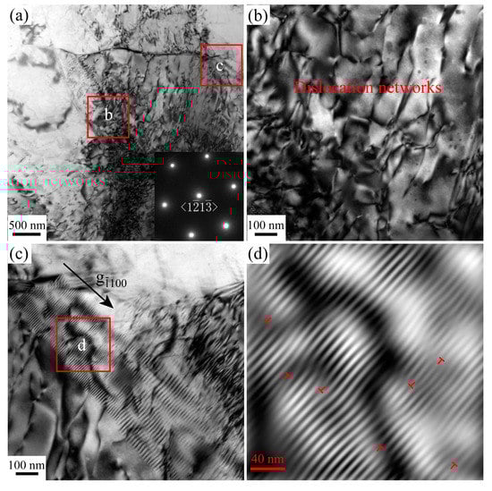
Figure 8.
(a) TEM image in outer region of AZ31B bar processed by pure torsion along a direction; (b) local magnification of position b in a; (c) local magnification of position c in a; (d) local magnification of position d in c.
Figure 7 and Figure 8 present the bright field TEM micrographs of AZ31B magnesium alloy processed by pure torsion. Because of strain gradient in pure torsion, plastic deformation increases from the center to the outer side. Small plastic deformation results in low density dislocations in Figure 7b. Medium density dislocations accumulate between center and outer zone (Figure 7c). High density dislocations are observed in outer region (Figure 7d). Detailed TEM images in Figure 8 show that dislocation networks and dislocation glides are the typical microstructures in outer region of AZ31B bar processed by pure torsion. Dislocation networks help to improve the yield strength. Dislocation glides resulting from strain gradient can suppress the localization of plastic deformation. The combination of dislocation networks and dislocation glide explains the high yield strength and high ductility of AZ31B processed by pure torsion (Figure 3).
4. Discussion
The dislocation density and strain hardening rate are directly related with the mechanical properties of metallic materials. As for metals undergoing plastic deformation, the evolution of dislocation density is determined by Kocks–Mecking–Estrin (KME) model [27,28,29,30]:
In Equation (1), is the dislocation density, is the effective plastic strain, is typically in the order of the grain size, is the Taylor factor, and are, respectively, the dislocation storage rate and dynamic recovery rate. The initial dislocation density for is assumed to be , and then the dislocation density in AZ31B after ECAP is determined by integrating Equation (1) from 0 to 0.6. The TEM images in Figure 6 indicate the accumulation of dislocation density . Based on Taylor Equation [31,32], the yield stress of AZ31B after ECAP is given by:
where is the yield strength of initial workpiece, is a constant of dislocation interaction, is Burgers vector, and is the shear modulus of initial workpiece. According to Equation (2), the additional dislocation density improves the yield strength of AZ31B after ECAP. Equation (2) explains the improvement of yield strength in Figure 3.
In the case of pure torsion, the strain along radius direction is a variable:
where is the distance departing from the center of bar. The SSD resulting from plastic strain is a variable:
The mean SSD in the crossing section after pure torsion is calculated by:
where is the diameter of AZ31B bar.
The strain gradient is 1/m during torsion, so that geometrically necessary dislocation (GND) density is determined by [33]:
Based on the experimental observations in Figure 7 and Figure 8, both SSDs and GNDs appear in AZ31B processed by pure torsion. The total dislocation density is sum of SSD density and GND density. Referring to Taylor Equation [31,32], the yield stress is determined by the total dislocation density. Using Equations (5) and (6), the yield stress of AZ31B after pure torsion is given by [33]:
In Equation (7), the additional SSD density and GND density improve the yield strength of AZ31B after pure torsion. By deriving Equation (7) by strain , the strain hardening rate of AZ31B after pure torsion is composed by two parts:
The term in Equation (8) is forest dislocation hardening. The other term in Equation (8) results from back stress hardening. According to the experimental observations [34], some sub-boundaries can be crucified to geometrically necessary boundary (GNB) which plays as obstacles to dislocation-slip like a grain boundary. GNBs help to the improvement of strength. Because the constraint and mechanical incompatibility [35] between different layers are produced in AZ31B with gradient dislocation density, the GNDs are associated with the back stress hardening [36]. The additional strain hardening property delays the deformation localization during tensile deformation. This explains the enhanced fracture strain of AZ31B after pure torsion (Figure 3).
Substituting the values of material parameters (Table 2), referred to [19,37], into Equations (1)–(6), the dislocation density distributions for AZ31B processed by different deformation modes can be obtained. The effective plastic strain field is homogeneous distribution in AZ31B bar processed by ECAP [11]. Using Runge-Kutta method [38], ordinary differential equation (ODE) (1) can be solved in the following forms:
Table 2.
Material parameters for AZ31B.
In Equation (9), is the increment step size of effective plastic strain. is defined as the number of total calculation steps. Variable i ranges from 1 to . For ECAP, , , , and . Here, was chosen to be 10,000 to reduce the calculation error. The increment step size of effective plastic strain is equal to 6 × 10⁻⁵. Based on Equation (9) and the initial values, the dislocation density of AZ31B processed by ECAP is shown as blue dash line in Figure 9.
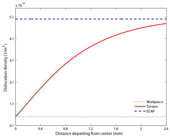
Figure 9.
Dislocation density distribution along radius direction for AZ31B processed by different deformation modes.
According to Equation (3), the effective plastic strain is related with the distance departing from the center of bar. The radius of 2.4 mm is assumed to be divided into equal parts. Variable ranges from 1 to . and are, respectively, equal to 0 and 2.4 mm. Then, variable is equal to . Based on Equation (3), the effective plastic strain in the position with the radius of is as follows:
It is derived from Equation (10) that and . The effective plastic strain field is gradient distribution in AZ31B bar processed by pure torsion. Equation (1) illustrates that SSD density after pure torsion is directly determined by the effective plastic strain . Runge–Kutta method [38] was employed again to solve Equation (1) in the condition of the effective plastic strain . The number of total calculation steps is also 10,000. For pure torsion, , , , and . The corresponding increment step size of effective plastic strain is given by:
The SSD density in AZ31B bar processed by pure torsion can be calculated by the following equations:
In Equation (12), and . Combining Equations (11) and (12), SSD density in AZ31B, processed by pure torsion , is obtained by calculating . plus gives the dislocation distribution in AZ31B processed pure torsion, which is illustrated by the red line in Figure 9. The dislocation density of AZ31B processed by ECAP is higher than that of the initial workpiece. This explains the higher yield strength in Figure 3. As for AZ31B processed by pure torsion, the strain gradient induces the gradient of dislocation density. Compared with the initial workpiece, AZ31B processed by pure torsion possesses higher mean dislocation density and the dislocation density gradient. The high yield strength and high ductility of AZ31B in Figure 3 are attributed to the combination of high dislocation density and dislocation density gradient.
The beginning of deformation localization under compression is predicted well by the work hardening coefficient [39]:
where is the compressive true stress and is the compressive true strain. If , deformation localization happens during the compression loading process. Based on the experimental data in Figure 3, the compressive true stress vs. compressive true plastic strain curves are shown in Figure 10a and the corresponding work hardening coefficients are illustrated in Figure 10b. The strain for flow localization of AZ31B processed by ECAP is less than that of initial AZ31B. The strain for flow localization of AZ31B processed by pure torsion is nearly the same as that of initial workpiece. As shown in Figure 10b, the good work hardening property can lead to the large fracture strain. According to Equations (7) and (8), the method of imposing strain gradient on materials is valid to improve the ductility of magnesium alloy.
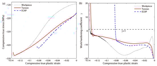
Figure 10.
(a) Compressive true stress vs. compressive true plastic strain curves for AZ31B processed by different deformation modes; (b) work hardening coefficient vs. compressive true plastic strain curves for AZ31B processed by different deformation modes.
5. Conclusions
In this work, magnesium alloy AZ31B bars were processed by two types of plastic deformation technology, i.e., equal channel angular pressing (ECAP) at the effective plastic strain of 0.6 and pure torsion at the radian of . The mechanical properties of AZ31B bars processed by different deformation modes were compared. The microstructures were characterized to reveal their effects on the mechanical properties. The following conclusions can be summarized:
- (1)
- Compared with the initial workpiece, AZ31B processed by ECAP possesses higher yield strength but less ductility; however, AZ31B processed by pure torsion has a higher yield strength with no sacrifice of ductility.
- (2)
- Microstructural observations show that the high strength and high ductility of AZ31B processed by pure torsion can be attributed to the inhomogeneous microstructures, i.e., the gradient of dislocation density combined with dislocation glide and dislocation networks.
- (3)
- Theoretical analyses reveal that plastic deformation leads to the accumulation of statistically stored dislocations (SSDs) and geometrically necessary dislocations (GNDs) result from strain gradient during pure torsion. SSDs help to improve yield strength and GNDs can enhance the ductility by introducing extra work hardening. The combination of SSD and GND can simultaneously improve the strength and ductility of magnesium alloy.
Author Contributions
Y.L. performed the preparation of samples and their tests. Y.L. and S.C. discussed the results and wrote the manuscript with contributions from all authors. S.C. conceived and supervised the project. All correspondence should be addressed to S.C.
Funding
This research was funded by the National Natural Science Foundation of China (grant numbers 11802013 and 11602236), Fundamental Research Funds for the Central Universities (grant number FRF-TP-18-020A2), and China Scholarship Council.
Acknowledgments
The authors wish to acknowledge Basic Experimental Center for Natural Science from University of Science and Technology Beijing for supplying material test system.
Conflicts of Interest
The authors declare no conflict of interest.
Appendix A
Here, a method based on the literature [40] was used to measure the dislocation density. The projected length of dislocation lines () in TEM image was measured by means of image analysis technology. Assuming the dislocations are randomly oriented, the dislocation density is given by:
In Equation (A1), is dislocation density, the volume of observed region is determined by multiplying the area () by the sample thickness (). In TEM image of Figure A1a, at least five different regions were chosen to measure the dislocation density. Substituting the length of dislocation lines () measured in Figure A1c into Equation (A1), the dislocation density was obtained. The mean dislocation density of at least five different regions was calculated to determine the dislocation density of Figure A1a.

Figure A1.
(a) Bright-field TEM micrograph of AZ31B where several regions were chosen to measure dislocation density; (b) magnification of the area in (a) delimited by a black square; (c) the same micrograph as in (b), where the black lines define the path considered for determination of .
References
- Abu-Farha, F.K.; Khraisheh, M.K. Mechanical characteristics of superplastic deformation of AZ31 magnesium alloy. J. Mater. Eng. Perform. 2007, 16, 192–199. [Google Scholar] [CrossRef]
- Janeček, M.; Čížek, J.; Gubicza, J.; Vrátná, J. Microstructure and dislocation density evolutions in MgAlZn alloy processed by severe plastic deformation. J. Mater. Sci. 2012, 47, 7860–7869. [Google Scholar] [CrossRef]
- Zhang, L.; Yu, G.; Tian, C.; He, X.; Li, S. Grain refinement of hypereutectic immiscible Cu-50Cr alloy during rapid melting and solidification induced by high power density laser beams. Metals 2019, 9, 585. [Google Scholar] [CrossRef]
- Wu, Y.; Guo, Y.; Xu, G.; Chang, H.; Cui, Y. Effects of trace erbium addition on microstructure and mechanical properties of Ti6Al4V-xEr alloys. Metals 2019, 9, 628. [Google Scholar] [CrossRef]
- Qiu, G.; Zhan, D.; Li, C.; Yang, Y.; Qi, M.; Jiang, Z.; Zhang, H. Influence of inclusions on the mechanical properties of RAFM steels via Y and Ti addition. Metals 2019, 9, 851. [Google Scholar] [CrossRef]
- Han, D.; He, J.-X.; Guan, X.-J.; Zhang, Y.-J.; Li, X.-W. Impact of short-range clustering on the multistage work-hardening behavior in Cu–Ni alloys. Metals 2019, 9, 151. [Google Scholar] [CrossRef]
- Al-Samman, T.; Gottstein, G. Room temperature formability of a magnesium AZ31 alloy: Examining the role of texture on the deformation mechanisms. Mater. Sci. Eng. A 2008, 488, 406–414. [Google Scholar] [CrossRef]
- Yamashita, A.; Horita, Z.; Langdon, T.G. Improving the mechanical properties of magnesium and a magnesium alloy through severe plastic deformation. Mater. Sci. Eng. A 2001, 300, 142–147. [Google Scholar] [CrossRef]
- Gholinia, A.; Humphreys, F.J.; Prangnell, P.B. Production of ultra-fine grain microstructures in Al-Mg alloys by coventional rolling. Acta Mater. 2002, 50, 4461–4476. [Google Scholar] [CrossRef]
- Liu, Q.; Song, J.; Pan, F.; She, J.; Zhang, S.; Peng, P. The edge crack, texture evolution, and mechanical properties of Mg-1Al-1Sn-Mn alloy sheets prepared using on-line heating rolling. Metals 2018, 8, 860. [Google Scholar] [CrossRef]
- Segal, V.M.; Reznikov, V.I.; Drobyshevskiy, A.E.; Kopylov, V.I. Plastic working of metals by simple shear. Russ. Metall. 1981, 1, 99–105. [Google Scholar]
- Smirnova, N.A.; Levit, V.I.; Pilyugin, V.I.; Kuznetsov, R.I.; Davydova, L.S.; Sazonova, V.A. Evolution of the fcc single-crystal structure during severe plastic deformations. Fiz. Met. Metalloved. 1986, 61, 1170–1177. [Google Scholar]
- Saito, Y.; Utsunomiya, H.; Tsuji, N.; Sakai, T. Novel ultra-high straining process for bulk materials—development of the accumulative roll-bonding (ARB) process. Acta Mater. 1999, 47, 579–583. [Google Scholar] [CrossRef]
- Figueiredo, R.B.; Langdon, T.G. The development of superplastic ductilities and microstructural homogeneity in a magnesium ZK60 alloy processed by ECAP. Mater. Sci. Eng. A 2006, 430, 151–156. [Google Scholar] [CrossRef]
- Jin, L.; Lin, D.; Mao, D.; Zeng, X.; Ding, W. Mechanical properties and microstructure of AZ31 Mg alloy processed by two-step equal channel angular extrusion. Mater. Lett. 2005, 59, 2267–2270. [Google Scholar] [CrossRef]
- Kai, M.; Horita, Z.; Langdon, T.G. Developing grain refinement and superplasticity in a magnesium alloy processed by high-pressure torsion. Mater. Sci. Eng. A 2008, 488, 117–124. [Google Scholar] [CrossRef]
- Perez-Prado, M.T.; del Valle, J.A.; Contreras, J.M.; Ruano, O.A. Microstructural evolution during large strain hot rolling of an AM60 Mg alloy. Scr. Mater. 2004, 50, 661–665. [Google Scholar] [CrossRef]
- Lapovok, R.; Thomson, P.F.; Cottam, R.; Estrin, Y. Processing routes leading to superplastic behaviour of magnesium alloy ZK60. Mater. Sci. Eng. A 2005, 410–411, 390–393. [Google Scholar] [CrossRef]
- Liu, Y.; Cai, S.; Dai, L. A new method for grain refinement in magnesium alloy: High speed extrusion machining. Mater. Sci. Eng. A 2016, 651, 878–885. [Google Scholar] [CrossRef][Green Version]
- Wang, Q.D.; Chen, Y.J.; Lin, J.B.; Zhang, L.J.; Zhai, C.Q. Microstructure and properties of magnesium alloy processed by a new severe plastic deformation method. Mater. Lett. 2007, 61, 4599–4602. [Google Scholar] [CrossRef]
- Hilšer, O.; Rusz, S.; Szkandera, P.; Čížek, L.; Kraus, M.; Džugan, J.; Maziarz, W. Study of the microstructure, tensile properties and hardness of AZ61 magnesium alloy subjected to severe plastic deformation. Metals 2018, 8, 776. [Google Scholar] [CrossRef]
- Yuan, Y.; Guo, Q.; Sun, J.; Liu, H.; Xu, Q.; Wu, Y.; Song, D.; Jiang, J.; Ma, A. High mechanical properties of AZ91 Mg alloy processed by equal channel angular pressing and rolling. Metals 2019, 9, 386. [Google Scholar] [CrossRef]
- Vinogradov, A.; Vasilev, E.; Kopylov, V.I.; Linderov, M.; Brilevesky, A.; Merson, D. High performance fine-grained biodegradable Mg-Zn-Ca alloys processed by severe plastic deformation. Metals 2019, 9, 186. [Google Scholar] [CrossRef]
- Giannopoulou, D.; Dieringa, H.; Bohlen, J. Influence of AlN nanoparticle addition on microstructure and mechanical properties of extruded pure magnesium and an aluminum-free Mg-Zn-Y alloy. Metals 2019, 9, 667. [Google Scholar] [CrossRef]
- Tekumalla, S.; Ajjarapu, M.; Gupta, M. A novel turning-induced-deformation based technique to process magnesium alloys. Metals 2019, 9, 841. [Google Scholar] [CrossRef]
- Wei, Y.; Li, Y.; Zhu, L.; Liu, Y.; Lei, X.; Wang, G.; Wu, Y.; Mi, Z.; Liu, J.; Wang, H.; et al. Evading the strength–ductility trade-off dilemma in steel through gradient hierarchical nanotwins. Nat. Commun. 2014, 5, 3580. [Google Scholar] [CrossRef]
- Shterner, V.; Molotnikov, A.; Timokhina, I.; Estrin, Y.; Beladi, H. A constitutive model of the deformation behaviour of twinning induced plasticity (TWIP) steel at different temperatures. Mater. Sci. Eng. A 2014, 613, 224–231. [Google Scholar] [CrossRef]
- Mecking, H.; Kocks, U.F. Kinetics of flow and strain-hardening. Acta Metall. 1981, 29, 1865–1875. [Google Scholar] [CrossRef]
- Kubin, L.P.; Estrin, Y. Evolution of dislocation densities and the critical conditions for the Portevin-Le Châtelier effect. Acta Metall. Mater. 1990, 38, 697–708. [Google Scholar] [CrossRef]
- Estrin, Y.; Mecking, H. A unified phenomenological description of work hardening and creep based on one-parameter models. Acta Metall. 1984, 32, 57–70. [Google Scholar] [CrossRef]
- Taylor, G.I. The mechanism of plastic deformation of crystals, Part I—Theoretical. Proc. R. Soc. Lond. Ser. A 1934, 145, 362–387. [Google Scholar] [CrossRef]
- Taylor, G.I. Plastic strian in metals. J. Inst. Met. 1938, 62, 307–325. [Google Scholar]
- Gao, H.; Huang, Y.; Nix, W.D.; Hutchinson, J.W. Mechanism-based strain gradient plasticity—I. Theory. J. Mech. Phys. Solids 1999, 47, 1239–1263. [Google Scholar] [CrossRef]
- Liu, Q.; Huang, X.; Lioyd, D.J.; Hansen, N. Microstructure and strength of commercial purity aluminium (AA 1200) cold-rolled to large strains. Acta Mater. 2002, 50, 3789–3802. [Google Scholar] [CrossRef]
- Wu, X.L.; Jiang, P.; Chen, L.; Yuan, F.P.; Zhu, Y.T. Extraordinary strain hardening by gradient structure. Proc. Natl. Acad. Sci. USA 2014, 111, 7197–7201. [Google Scholar] [CrossRef]
- Yuan, F.; Chen, P.; Feng, Y.; Jiang, P.; Wu, X. Strain hardening behaviors and strain rate sensitivity of gradient-grained Fe under compression over a wide range of strain rates. Mech. Mater. 2016, 95, 71–82. [Google Scholar] [CrossRef]
- Ding, R.; Guo, Z.X. Coupled quantitative simulation of microstructural evolution and plastic flow during dynamic recrystallization. Acta Mater. 2001, 49, 3163–3175. [Google Scholar] [CrossRef]
- Jonas, J.J.; Holt, R.A.; Coleman, C.E. Plastic stability in tension and compression. Acta Metall. 1976, 24, 911–918. [Google Scholar] [CrossRef]
- Butcher, J.C. Numerical Methods for Ordinary Differential Equations, 3rd ed.; John Wiley & Sons: Chichester, UK, 2016; pp. 97–107. [Google Scholar]
- Bailey, J.E.; Hirsch, P.B. The dislocation distribution, flow stress, and stored energy in cold-worked polycrystalline silver. Philos. Mag. 1960, 5, 485–497. [Google Scholar] [CrossRef]
© 2019 by the authors. Licensee MDPI, Basel, Switzerland. This article is an open access article distributed under the terms and conditions of the Creative Commons Attribution (CC BY) license (http://creativecommons.org/licenses/by/4.0/).