Article

A CPS-Based Simulation Platform for Long Production Factories

1
Scuola Superiore Sant’Anna, TeCIP Institute ICT-COISP Center, Via Moruzzi 1, 56124 Pisa, Italy
2
ASINCO GbbH—Advanced Solutions for Industrial Control Am Kiekenbusch 11a, 47269 Duisburg, Germany
*
Author to whom correspondence should be addressed.
Metals 2019, 9(10), 1025; https://doi.org/10.3390/met9101025
Submission received: 21 August 2019 / Revised: 18 September 2019 / Accepted: 19 September 2019 / Published: 21 September 2019
(This article belongs to the Special Issue Modeling and Simulation of Metal Processing)

Abstract

:
Production technology in European steel industry has reached such a level, that significant improvements can only be reached by through process optimization strategies instead of separately improving each process step. Therefore, the connection of suitable technological models to describe process and product behavior, methods to find solutions for typical multi-criterial decisions, and a strong communication between involved plants is necessary. In this work, a virtual simulation platform for the design of cyber-physical production optimization systems for long production facilities focusing on thermal evolution and related material quality is presented. Models for describing physical processes, computers, software and networks as well as methods and algorithms for through process optimization were implemented and merged into a new and comprehensive model-based software architecture. Object-oriented languages are addressed and used because they provide modularity, a high-level of abstraction and constructs that allow direct implementation and usage of the cyber-physical production systems concepts. Simulation results show how the proper connection between models, communication, and optimization methods allows feasibility, safety and benefits of cyber-physical production systems to be established. Furthermore, the software architecture is flexible and general and thus, can be transferred to any steel production line as well as outside the steel industry.

1. Introduction

The production of long steel products has a long, successful history and is still very relevant for the European steel industry. Production processes are well established and on a high quality level. Nevertheless, long products are produced worldwide and market globalization is challenging producers due to the strong competition on both qualitative and economic aspects. As staff and energy costs are comparably high in Europe, the best chances for European companies producing long products to keep their market shares lie in the efficient production of high-quality products [1]. Consequently, improvements and the introduction of new technologies must usually be integrated into existing infrastructure. “Brown-field” development, which underlies a lot of constraints, stands in contrast to newly constructed “green-fields”, figuratively delineating the building of new steel works from scratch. The traditional individual process optimization solutions frequently lead to a heterogeneous communication and interface-nature for specific aggregates. A few standardized interfaces are available for communication among sub-processes. Common interfaces as a basis for a more complex through process consideration and eventual optimization, are often missing today. For most steps in the process of production, simulation models are already available, but not all of them have the required accuracy (e.g., thermal evolution models). In some sub-process steps, simulation models are still missing, so there are several roadblocks, which make a through process optimization very difficult.
Within the steel industry improved through process optimization has been proposed by coupling several processes on a basic (IT) level [2]. This approach has been mainly focused on developing optimization algorithms in detail. In [3], a conventional centralized scheduling system for stainless steel production is described. Production scheduling by simulation is a topic addressed in [4] for the continuous casting, rolling and finishing departments. In [5], the charge planning problem of steelmaking process is discussed and a solution based on a multi-objective evolutionary algorithm is proposed. The optimization of the continuous galvanizing heat treatment process by exploiting multi-objective optimization has recently been presented in [6]. However, these examples apply conventional through process approaches and communication aspects are not considered. One effective way to exploit the connection of suitable technological models describing process and product behavior, methods to find solutions for typical multi-criterial decisions and a strong communication between involved plants, is the integration of through process optimization with cyber-physical systems (CPS) technologies. CPS are systems composed of physical subsystems together with computing and networking resources/facilities. Embedded computers and networks monitor and control the physical processes, usually with feedback loops, where physical processes affect computations and vice versa [7]. Europe accounts for 30% of world production of embedded systems/CPS with strengths in the automotive sector, aerospace and health [8]. The use of CPS in production systems, also called cyber-physical production systems (CPPS), leads to the so-called “smart factory”, a paradigm offering advantages regarding quality, time and costs in comparison with classical production systems [9]. Modelling processes operation and forecasting their emergent behaviors raises a series of basic, application-oriented research tasks, not to mention the control of any level of these systems [10]. However, there are still technological and knowledge gaps in the industrial sector, specifically in the steel industry, which make complete adoption of this new technology challenging [11].
One effective approach to smoothly migrate towards CPPS is to develop and demonstrate the technology world virtually on a simulation platform, by encouraging steel companies to explore the potentials and opportunities provided by these new technologies and by paving the way to the transformation of conventional steelworks into smart factories. As stated by acatech in its position paper [12]: “Management of this type of system (i.e., CPS) requires theoretical approaches, which facilitate a merging of classic models of mechanical engineering and electrical engineering with the digital models of computer science. Rather abstract models created by computer scientists for dealing with information and knowledge processing need to be merged with models from the physical world to depict time and space”.
In this context, smart manufacturing concepts for the steel industry have been explored in some researches and industrial applications. In [13], a brief summary and perspective of intelligent technology carrying out in steel strip production is proposed. A distributed intelligence-based system concept for modeling and self-optimizing the production of flat steel products was presented in [14], where the decentral optimization of the production scheduling considers detailed product and process knowledge by using individual product properties and processing information of neighboring processes. A generic concept of agent-based factory and company-wide automation and information technology is described in [15], where single agents take their (optimal) decisions on the basis of a wide range of information related to the whole set of involved plants, machineries and coils (the resources), share their own information and aim at the maximization of a global performance index. Another interesting approach that leads to increasing productivity by enhancement of product intelligence, is mentioned in [16]. In [17], an architecture for storing and processing massive amounts of data that are created during steel manufacturing with the aim of improving the quality of steel production processes is presented.
As described earlier, a close examination of the existing literature indicates that cyber-physical production optimization is not yet widespread in the steel industry, and, in particular, is not used in long production facilities, despite its huge potential for reducing material and energy consumption, facilitating equipment evaluation and troubleshooting, and increasing economic benefits.
This paper presents a new and comprehensive virtual simulation platform for the design of cyber-physical production optimization systems (CPPOS) for long production facilities with special emphasis on thermal evolution and related material quality. Simulation and verification tools as well as a new IT framework for establishing the feasibility, safety and benefits of CPPS in the framework of “Steel Industry 4.0 Automation” are implemented. For this purpose, appropriate combined models, called CPPS models, which include process (thermal, rolling, transport) models, material-quality models, logistics/scheduling models and communication (computers, software, networks) models are merged and used for the production optimization. The through process optimization with respect to throughput, energy consumption and product quality is established by means of single and multi-objective optimization algorithms integrated within the models.
The paper is organized as follows: Section 2 describes the manufacturing process of long products; Section 3 presents the virtual CPPS platform architecture with the models describing products, physical processes and communication functionalities. Strategies and methods for through process optimization are also presented here. The simulation results and discussions are presented in Section 4. Finally, the conclusion is given in Section 5.

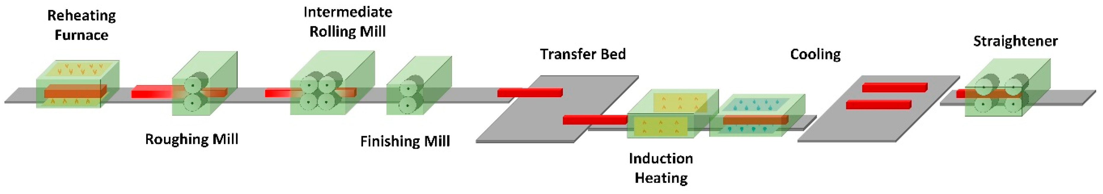
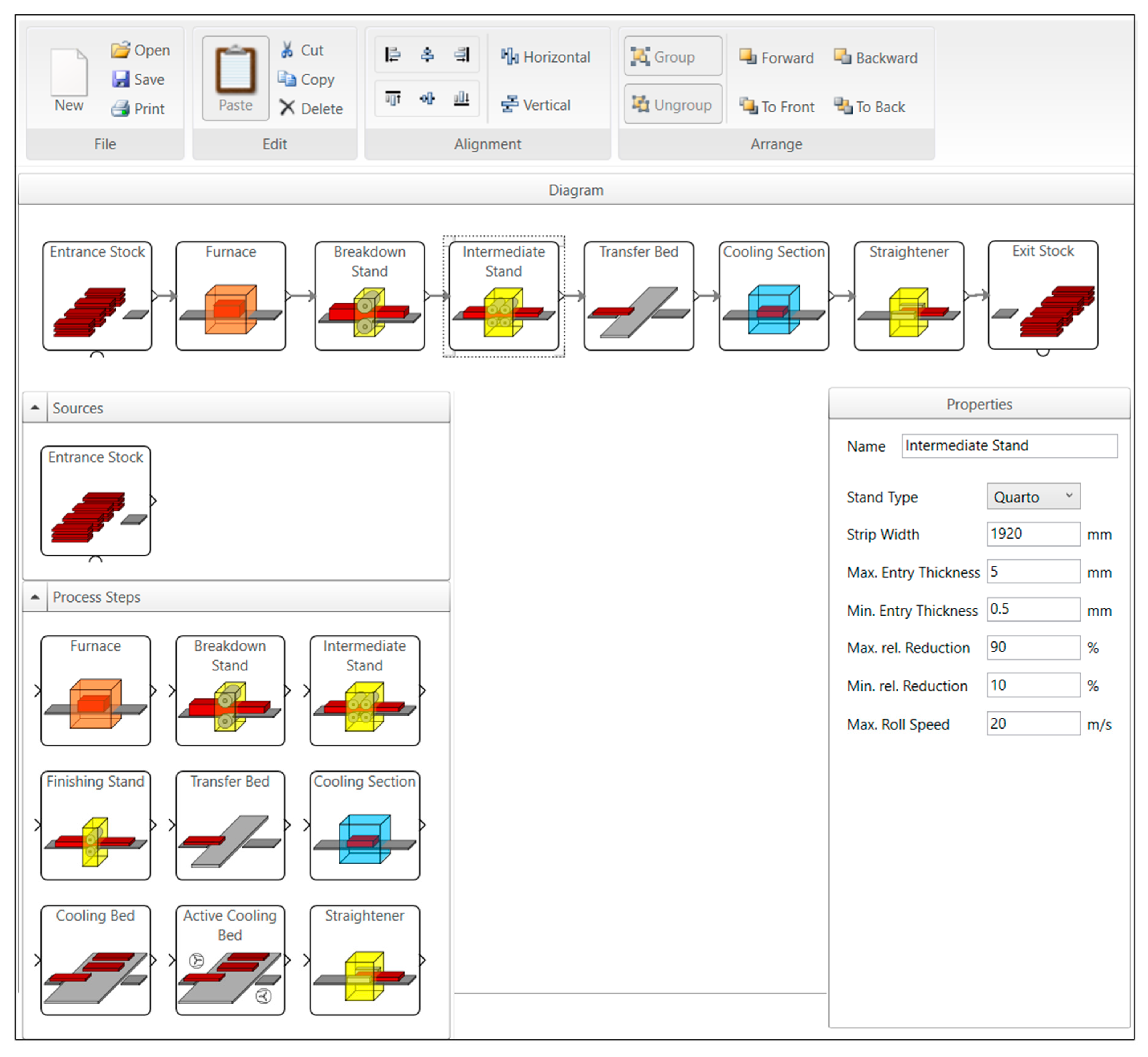
2. Long Products Manufacturing Process

Figure 1 shows an example of manufacturing process for long products (e.g., rails, pipes and tubes) downstream of the casting process. In particular, the following processes will be in focus [18]:
  • Reheating furnace;
  • Roughing mill;
  • Transfer bed;
  • Induction heating;
  • Active/passive cooling sections;
  • Straightener.
A short description of each process, including the information available that can be integrated within the cyber-physical processes and used for through process optimization is reported in the following subsections.

2.1. Reheating Furnace

In this furnace, semi-finished casting products such as blooms and billets are reheated up to the rolling temperature lying in the range between 1000 to 1300 °C. The reheating furnace is commonly separated into several zones, each one having different purposes that define its configuration and typical temperature level. Different strategies exist for heating the semi-finished products consisting on ramps or steps of temperature for a given time in order to ensure the correct homogeneous temperature at the end of the process with a minimum decarburized layer. Information available at this process step is:
  • Temperature evolution of the product;
  • Decarburization (available as indirect measurement);
  • Ambient temperature in each zone;
  • Oxygen and gas percentage composition and flow;
  • Product’s processing duration in each zone;
  • Transport speed of the furnace.

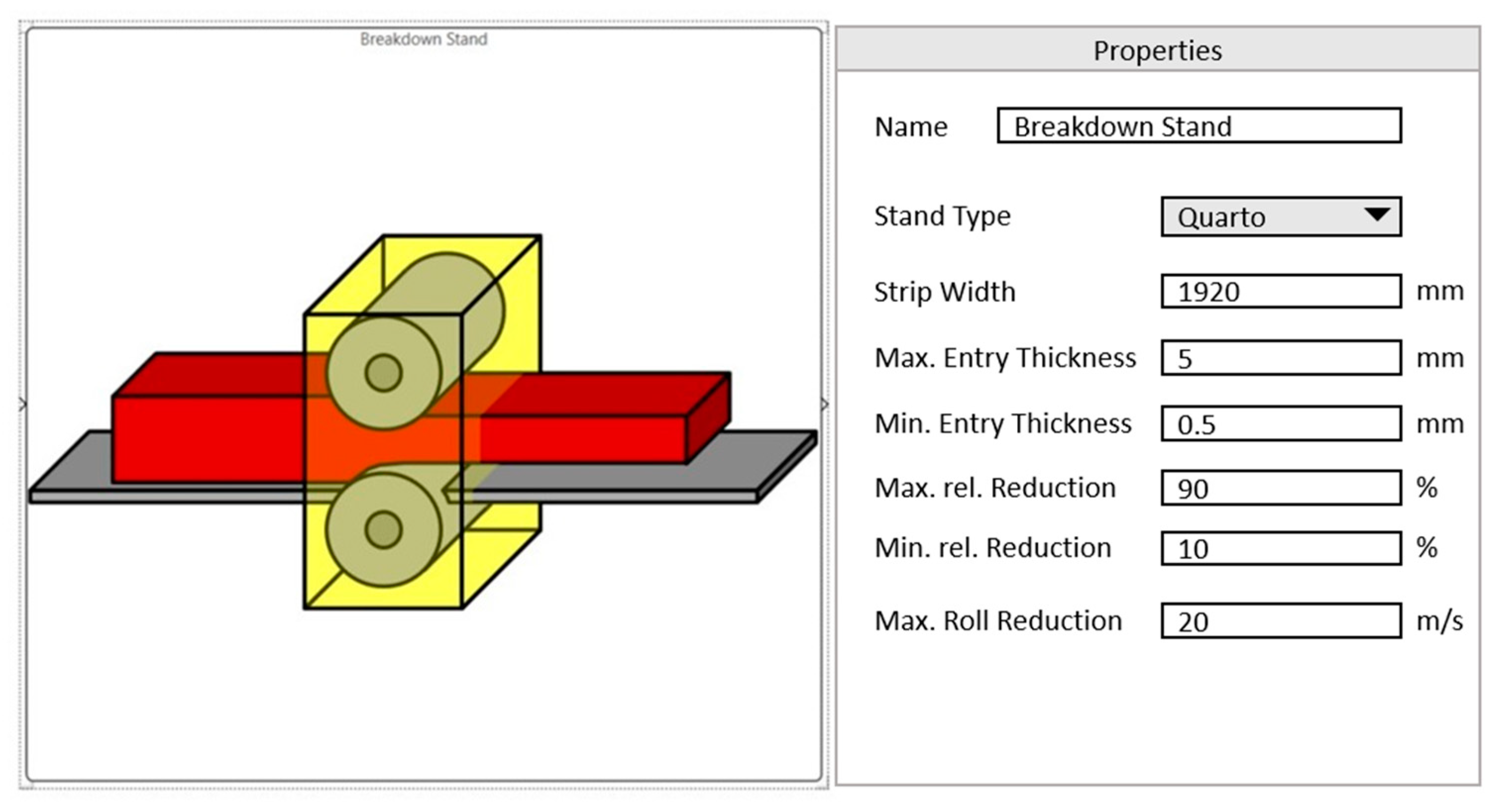
2.2. Rolling Section

The rolling section is generally composed of different stands where the semi-finished product sections are rolled. The number of the stands is determined by the ratio of the initial input material and final cross section of the finished product. Figure 1 depicts a classical configuration with three different processing steps composed by a roughing mill, an intermediate rolling mill and a finishing mill. The semi-finished product is continuously reshaped to be finally transformed into a specific finished product with cross section dimension and geometry according to a desired profile. Information available at this process step typically is:
  • Temperature at the entry of each stand;
  • Rolling forces and gaps;
  • Rolling speeds;
  • Rolling time.

2.3. Transfer Bed

After the rolling section, semi-finished products are transferred to the following section through the transfer bed. The direction of movement of the semi-finished products can be reversed with respect to the one at the rolling section according to the location of the next section. The time required to transport the semi-finished products to the following section can vary and depends on the target temperature at the entrance of the cooling section. Thus, the speed at which the semi-finished products move from this point can be regulated according to a selected strategy. In general, it is kept constant depending on the considered product. However, an increase of the productivity, and especially flexibility, with varying requirements for different products will require the use of different speeds. The information available at this process step is:
  • Temperature at the entry and exit along the rail length;
  • Duration at transfer bed;
  • Transport speed.

2.4. Induction Heating

Due to the long product’s nature the processing temperature at the entry of the cooling section would vary along the length, which can be usually above 20 m. This translates into a temperature gradient in the semi-finished products along their length at the entry of the cooling section. This situation must be avoided. Therefore, the aim of the induction heating system is to heat the comparably colder tails of the semi-finished products in order to have a homogeneous temperature at the entrance of the cooling section. Typically, this will be performed via a continuously (in most cases linear) increasing power of the induction system over the long product’s length. The induction heating system is usually composed of several inductors characterized by different length and power values. Information available at this process step is:
  • Power injected by inductors;
  • Temperature at the entry and exit of the induction section;
  • Transport speed in specific inductors;
  • Processing duration in specific inductors.

2.5. Cooling Section

The cooling section can be composed of an actively controlled cooling section and/or a passive cooling bed depending on the target quality of the final product, as depicted in Figure 1. The aim of the cooling section is to cool down the semi-finished products through a fluid in order to obtain certain material properties. The semi-finished products are usually cooled down by water flows in the controlled cooling, and by air in the cooling bed. The controlled cooling section is usually composed by several zones, each zone equipped by circuits of nozzles pointing to all different sides of the semi-finished product. The water flow rates can be independently controlled for each zone and inside each zone, for each circuit. The cooling bed can be actively controlled as well, by equipping it with fans that spread air at different speed and temperature values. Information available at this process step is:
  • Water flow rates per zone and circuit;
  • Fan speed and temperature;
  • Speed in the cooling section;
  • Duration in the cooling section;
  • Temperatures in transition between zones;
  • Temperatures at the entry and exit of the cooling section.

2.6. Straightener

The straightener process utilizes rollers to apply pressure on the surface of the semi-finished products. As the semi-finished products are moved between the rollers the bends and twists are removed. By adjusting the positions of the rollers, semi-finished products may be readily straightened. Information available at this process step is:
  • Rolling forces;
  • Rolling speeds;
  • Duration in the straightener.

3. Cyber-Physical Production Optimization Systems Platform

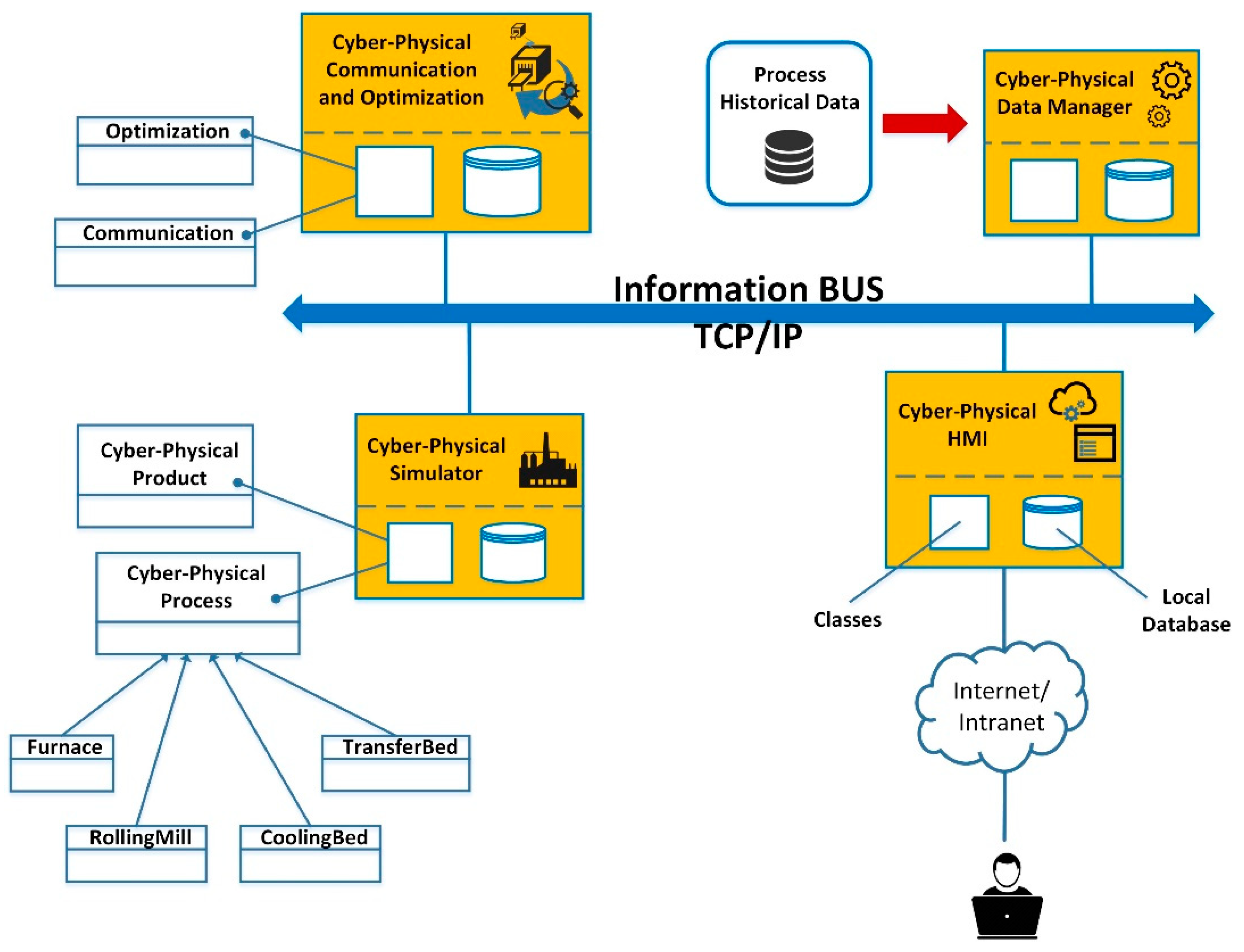
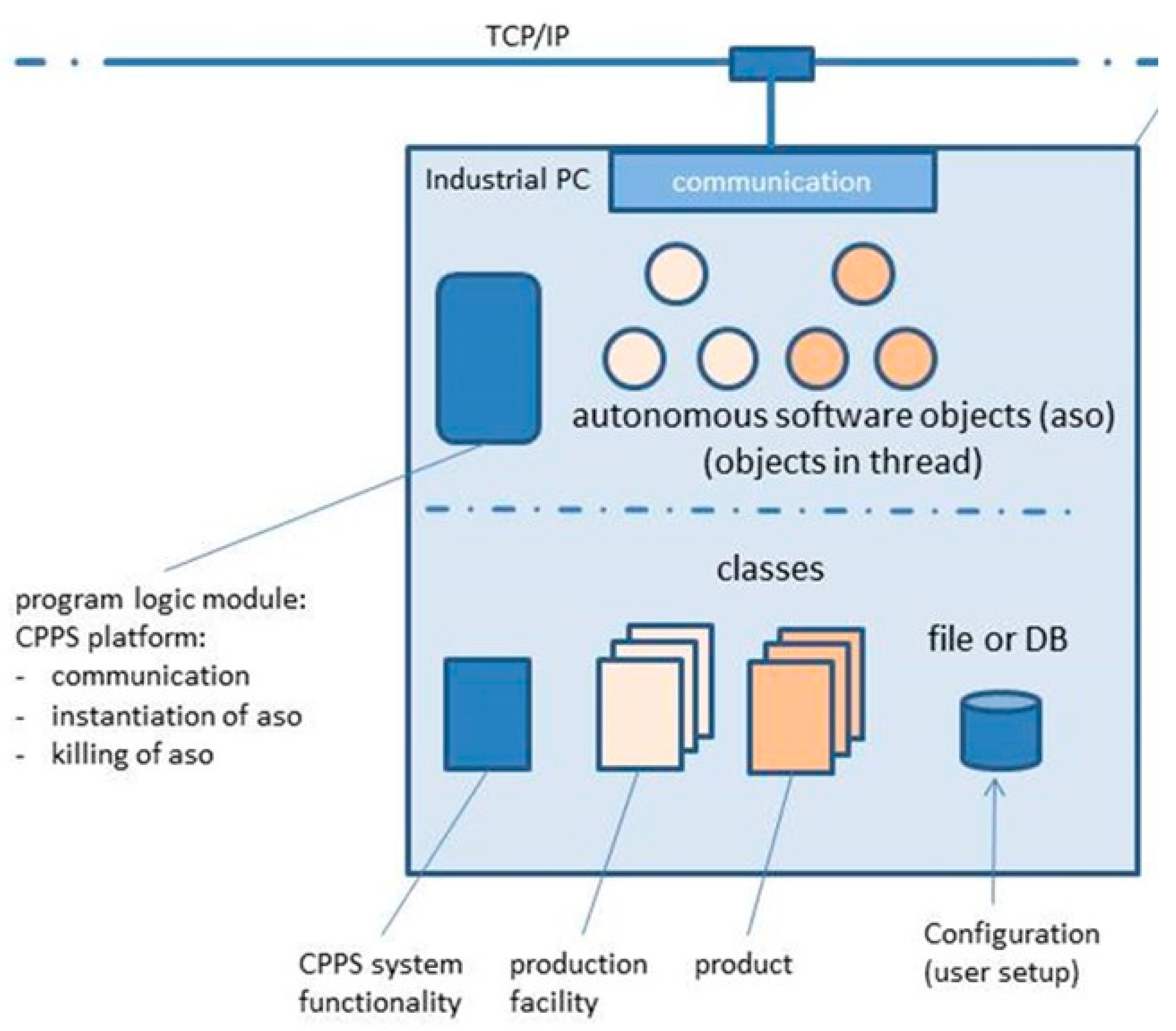
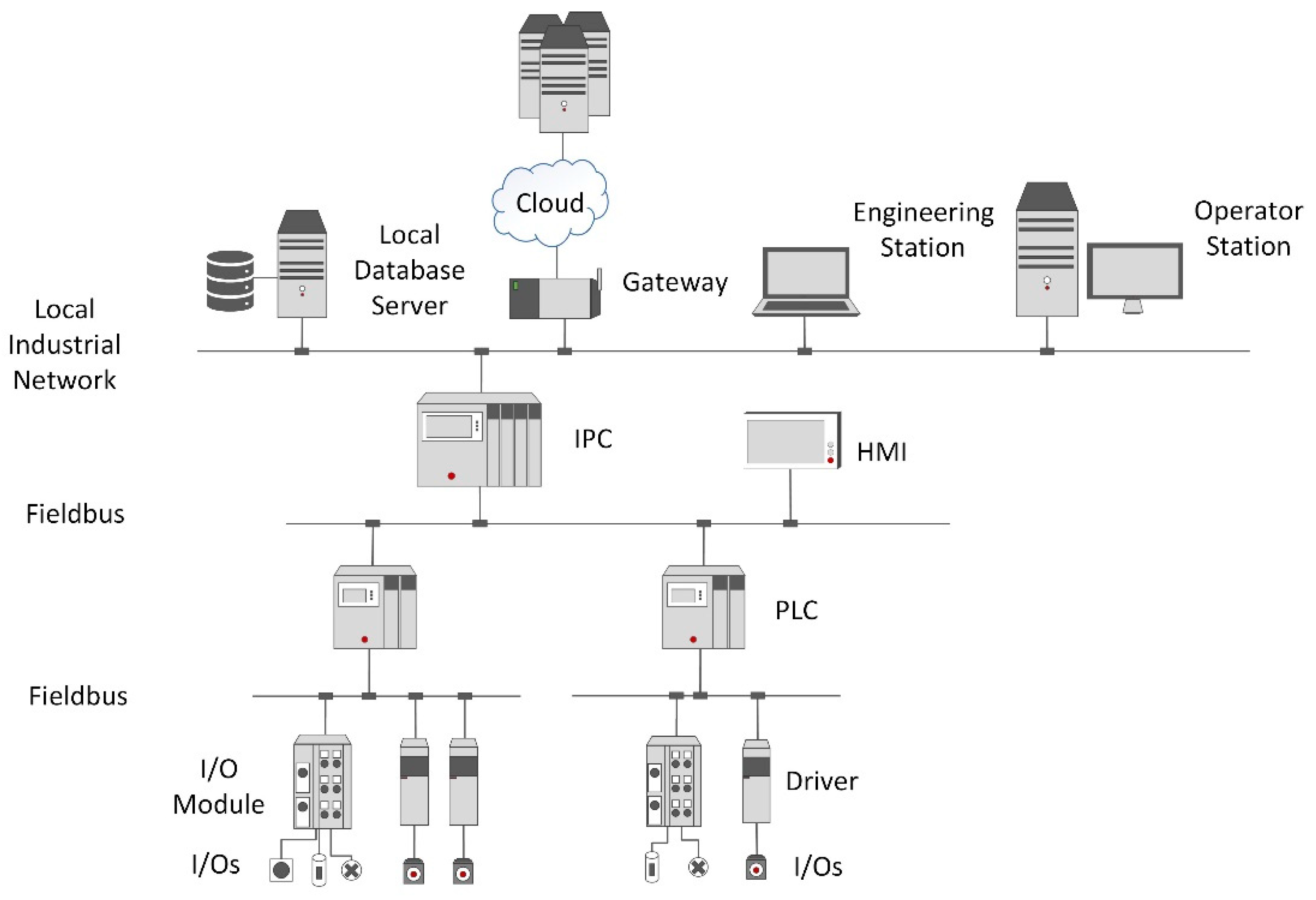
3.1. CPPS Architecture Design

The design of complex CPPS—especially the ones with heterogeneous subsystems distributed across processing lines and networks—is a demanding task. The challenges of establishing CPPS architectures are to operate sensor networks, handle big bulks of data, as well as to retrieve, represent, and interpret information. Also, novel modes of human–machine communication need to be realized in the course of establishing CPPS. Moreover, due to the complexity of the considered production system, the CPPS is software-intensive and requires high processing capacity. For that reason, the use of multi-core processors may be necessary, such as proposed in [19].
A modular architecture for the simulation of the CPPS platform has been developed, which can capture both the physical and the communication dynamics, providing a vast variety of modules, models, communication classes, objects, logic modules and global optimization functions. Different options for implementing the CPPS architecture were benchmarked such as MATLAB/Simulink R2018b, Modelica 3.4, AADL (Architecture Analysis & Design Language) and C# (C-Sharp). Object-oriented languages were addressed, because they provide modularity, a high-level of abstraction and constructs that allow direct implementation and usage of the CPPS concepts: Monitoring, self-optimization, communication, etc. The best choice was the object-oriented programming language C# (C-Sharp) in combination with the Microsoft Visual Studio with the utilizable “.Net-environment” [20]. Generally, C# shows several advantages over e.g., C++, Java or comparable languages:
  • Integrated “garbage collection” system;
  • Uses mainly advantages of real-time applicability from C++;
  • Large standard libraries;
  • Support of managed and integrated code blocks;
  • Simple handling of DLL-implementation;
  • Elegant implementation of properties and events;
  • Integrated resource-management;
  • High comfortability and integrity with Windows operating system;
  • Simple definition of new data types;
  • Possible integration of INTEL MKL library [21] for real-time processing;
  • Elegant option for “embedded systems” for integration in industrial plants.
The platform allows instantiating several autonomous objects, representing processes (cyber-physical process module) and products (cyber-physical product module). Each individual object must deliver information by event or request to a superordinate cyber-physical communication module. With this, it is possible to effectively optimize the overall production. The chosen infrastructure of the CPPS makes it independent of existing data source types and programming environment at the plants. Figure 2 shows overall coherences between implemented modules.
The solution comprises the following four main modules:
  • Cyber-physical data management: A module containing functions devoted to the connection and querying of the database where historical process data are stored.
  • Cyber-physical simulator: A module that runs plant simulations based on the status of the plant and a production plan provided by the user or by the cyber-physical communication and optimization module. The module is also composed of a cyber-physical product module and Cyber-physical process module. The first one enhances the product intelligence, it is continuously carried along by the respective product that is processed and includes product parameters, such as actual and target properties, logistic information regarding product process route, constraints, costs, etc. The second one implements the concept of the process line, the different sub-processes, such as the furnace, rolling mill, cooling, induction heating and transport are derived from this module.
  • Cyber-physical communication and optimization: A module that provides the communication protocols between software modules and objects and is responsible for the overall through process global optimization based on multi-criteria strategies. Two sub-modules respectively implement communication and optimization separately.
  • Cyber-physical Human Machine Interface (HMI): A module that shows all the relevant information of the modules (e.g., plant status, alarms, simulations and optimizations results, etc.) to the user. The module can be a web service or a local graphical user interface (GUI).
The main control of the platform is shown in Figure 3: It includes a program logic module for communication and instantiation/killing of objects. Targeted to be of universal usage, it is a general template for the whole network with one master communication module. Classes describing products and processes can be individually integrated. Interfaces for manual inputs and manipulations can be added.
A cyber-physical library has been created for the “drag-and-drop” implementation of CPPS for typical long product factories. The library consists of the following three families of modules:
  • Components and connectors for real-time monitoring and control.
  • Architectural/physical models (thermal models, material-quality models, logistics/scheduling models).
  • Elements for interaction between the cyber and the physical world.
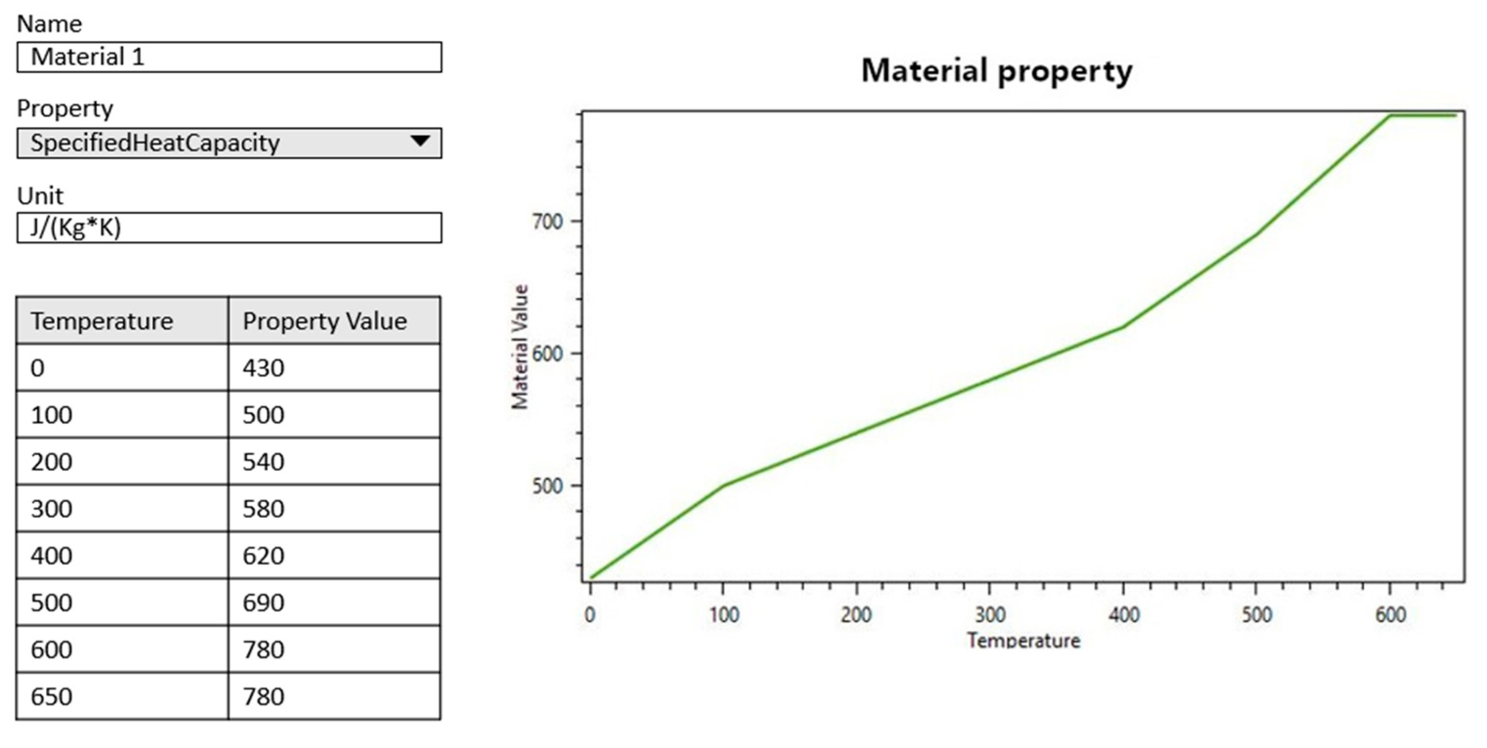
The “drag-and-drop” GUI is shown in Figure 4. Libraries offer an effective way of selecting respective processes. Different optimization algorithms can be selected. All necessary process steps must be adjusted and linked due to the correct production flow.

3.2. Product Module

An important part of the through process optimization is integrated by product modules. These modules are continuously carried along by the respective product, which is processed, and include its main, actual and target properties as well as logistic information regarding their process route. Some examples of this information is:
  • Actual temperature profile:
  • Actual properties (quality);
  • Target properties;
  • Control constraints (min/max temperature);
  • Logistic information (previous, actual and following processing steps);
  • Historical data.
Products can be easily added or created via a dedicated GUI. Main materials are selectable from a central data base, as exemplarily depicted in Figure 5. Here, also all available/to-be-processed products must be integrated by specifying their respective material properties, geometry and processing steps with respective processing target values for each modelled process step.

3.3. Process Module

Implemented process modules are placed at the respective aggregates. All these modules consist of internal online process models, logistic models and algorithms for the purpose of local process optimization. One main goal of this local process optimization is the calculation of constraints concerning the global through process optimization. Process-related boundary conditions and actual status are considered to communicate their constraints to the superordinate managing module. After implementation of specified process step models, an overall process simulation can be performed. There are specific models which can be parameterized via the CPPS-GUI, as exemplarily shown in Figure 6 for a generic mill stand.

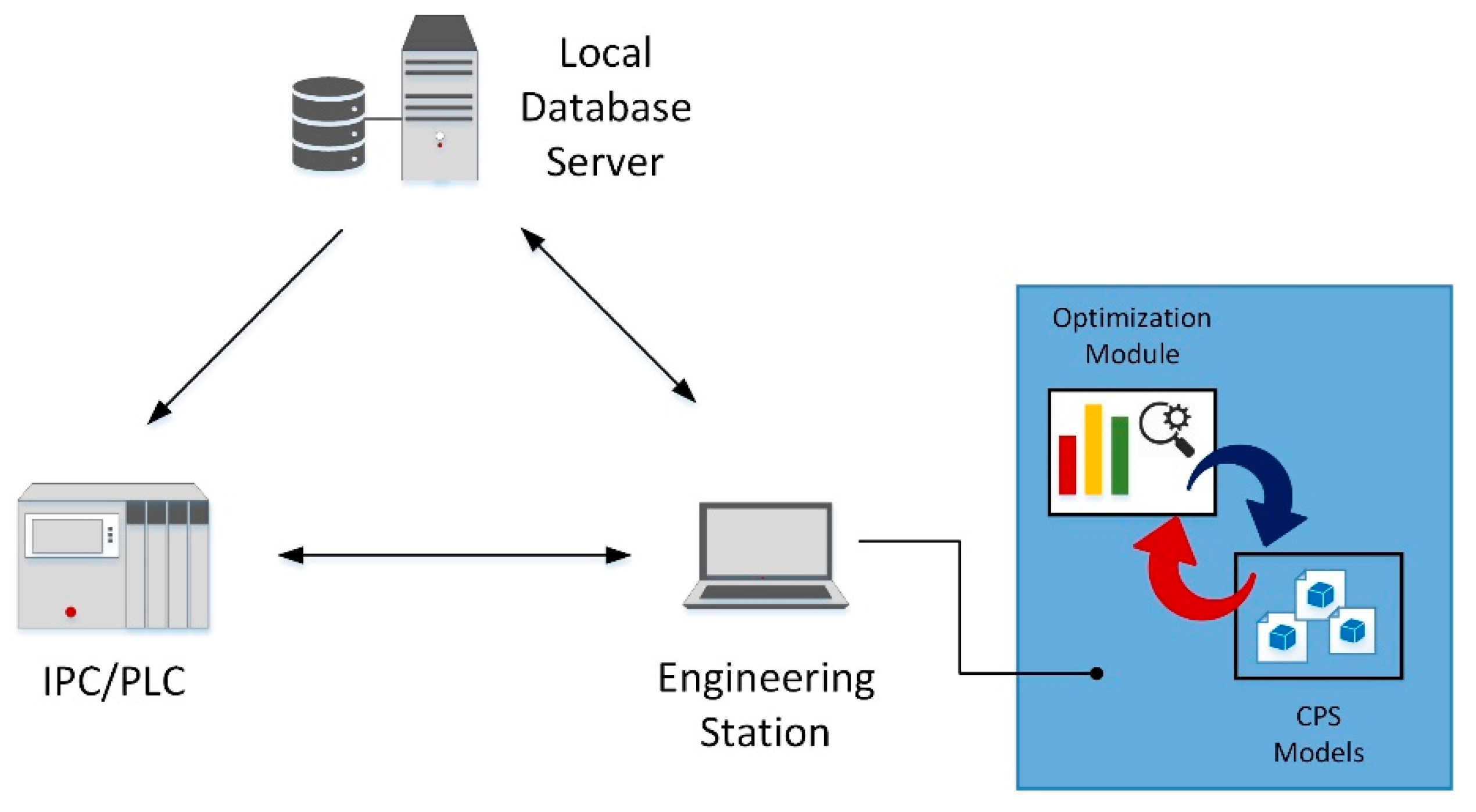
3.4. Communication and Optimization Module

The communication and optimization module dispatches the process step, manages the communication between software modules and objects and is responsible for the overall global optimization. As far as the optimization functionalities are concerned, several algorithms implemented from classical numerical methods to evolutionary algorithms and other approaches solving single or multi-objective optimization problems depend on the selected key performance indicators (KPIs), such as energy consumption, throughput, product quality, etc. This managing module computes the current optimized target parameters of the processes according to the information coming from the products and processes themselves. Communication and optimization functionalities are described in the next subsections.

3.4.1. Communication Module

In order to facilitate generic communication within this CPPS a common approach in web-development for distributed systems is available, which is based on representational state transfer (REST) [22]. A main advantage of this approach is the existing infrastructure of the world wide web (e.g., various parsers, security mechanisms, application server, etc.). Thereby, the CPPS can be implemented as a http-server and a specific controller within the application programming interface (API) can be set for accessing data, process/product configuration and, if necessary, time stamps. Possible codings, which are supported and practical for model implementation, are JavaScript Object Notation (JSON) [23] or Extensible Markup Language (XML) [24], which are both supported by C#. Both such codings offer human-readable text to transmit data objects consisting of serializable values (e.g., attribute-values or array data types). If needed, an even more compact format could be used, e.g., binary JSON (bJSON). This format can be implemented only if the overhead of the previously chosen ASCII-based protocols becomes too complex to run in a reasonable time, since it would mean higher development efforts. Based on the specified format, the object-call can be performed via http.

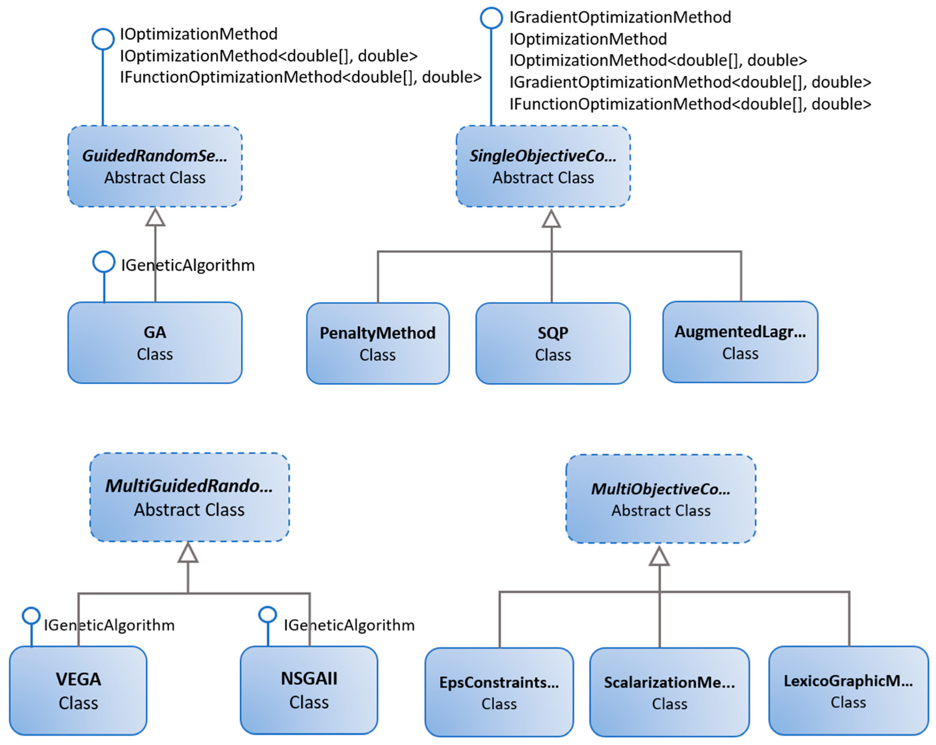
3.4.2. Optimization Module

Concerning the long products, the parameters to be optimized are product quality (mechanical properties, microstructure, product geometry, temperature evolution, heating/cooling trajectories), productivity (schedules/productions plans, throughput) and energy consumption, as well as occupational health and safety. In the present exemplar case, the main focus is on product quality: Optimization issues can be formalized as continuous nonlinear constrained optimization problems, where at least one nonlinear function is present among the objective function and the constraints. A formalization of these kind of optimization problems can be defined as:
min o r   m a x f ( x ) s u b j e c t   t o g i ( x ) 0   f o r   i = 1 , , m h j ( x ) = 0   f o r   j = 1 , , l x l x x u
where x R n are the optimization variables, f ( x ) : R n R is the objective function and g i ( x ) : R n R , i = 1 , , m are the inequality constraint functions, h j ( x ) : R n R , j = 1 , , l are the equality constraint functions and, x l and x u are the lower and upper bounds, respectively. The optimal solution x * shows the smallest or biggest value of f among all vectors that satisfy the constraints. This class of problems can be solved through classical numerical methods or evolutionary computation algorithms. Examples of solution techniques belonging to the former class are as follows:
  • Penalty method: The constrained optimization is transformed into an unconstrained problem by penalizing the objective function for any violation of the constraints.
  • Augmented Lagrangian method: A blend of both the penalty method and the Lagrangian multipliers method.
  • Sequential quadratic programming (SQP) method: A quadratic subproblem is solved in every iteration where the objective function is approximated by a quadratic function and the constraints are linearized.
An exhaustive description of the previously listed methods can be found in [25,26].
Evolutionary computation is a family of algorithms inspired by biological evolution and belonging to the soft computing or computational intelligence science field. These algorithms exploit population of points in the search space instead of a single point, such as in many classical numerical methods. Two very popular techniques are the genetic algorithms (GA) and particle swarm optimization (PSO). GA mimics the biological evolution process (led by the laws of genetics), whereas PSO is based on the idea of natural phenomena, such as birds flocking together or a school of fish moving together. An exhaustive description of the previous methods can be found in [27].
Classical numerical methods require the objective function to be either continuous or differentiable. The optimal solution depends on the selected initial conditions and they are more likely to stay at local optimums for multimodal objective functions, therefore they must be restarted to ensure that the reached local optimum is indeed the global one. Whereas evolutionary techniques do not require the objective function to be either continuous or differentiable, they are efficient in locating global optimum solutions.
Different optimization algorithms have been developed using object-oriented programming principles by means of the C# language supported by existing libraries and external tools. In the .NET-framework several existing toolboxes have been identified, analyzed and evaluated. The following toolboxes appear promising and have been tested based on standard optimization problems (e.g., Sphere, Ackley, Bukin n.6, Rosenbrock with and without constraints, MishraBird):
  • Math.NET is an open-source initiative to build and maintain toolkits covering fundamental mathematics, targeting advanced as well as the daily needs of .Net developers. Some of the main libraries are Numerics, which aims at providing methods and algorithms for numerical computations in science, engineering and everyday use; Symbolics, a basic open-source computer algebra library; Filtering, which aims at providing a toolkit for digital signal processing; Spatial, which aims at becoming a geometry library.
  • ALGLIB is a cross-platform numerical analysis and data processing library. It supports several programming languages (C++, C#, Delphi) and several operating systems (Windows and POSIX, including Linux). ALGLIB features include data analysis (e.g., classification/regression, statistics), optimization and nonlinear solvers, interpolation and linear/nonlinear least-squares fitting linear algebra (e.g., direct algorithms, Eigen Values Decomposition-EVD/Singular Value Decomposition-SVD), direct and iterative linear solvers, fast Fourier transform and many other algorithms.
  • GeneticSharp.Net is a fast, extensible, multi-platform and multithreading C# genetic algorithm library that simplifies the development of applications using genetic algorithms (GAs). GeneticSharp.Net features include a definition of different kind of chromosomes (e.g., floating, integer, binary), fitness evaluation and population generation, several selection, mutation, crossover and reinsertion techniques, termination control.
  • Accord.NET is a framework for scientific computing in .NET. The framework is comprised of multiple libraries encompassing a wide range of scientific computing applications, such as statistical data processing, machine learning, pattern recognition, including but not limited to, computer vision and computer audition. Some of the main libraries are Math, which contains a matrix extension library, along with a suite of numerical matrix decomposition methods, numerical optimization algorithms for constrained and unconstrained problems, special functions and other tools for scientific applications; Statistics, which contains probability distributions, statistical models and methods; MachineLearning, which contains techniques for regression, clustering and classification. Neuro which contains neural learning algorithms and neural network models.
Accord.Net [28] and GeneticSharp.Net [29] libraries have been selected for the purposes of the present work as they are free for commercial purposes, easy to use and with complete functionalities.
The implemented algorithms can solve single or multi-objective optimization problems depending on the KPIs selected and are the following:
  • Single objective optimization algorithms. In particular, penalty method, augmented Lagrangian method, SQP and GA.
  • Multi-objective optimization algorithms. In particular, scalarization method, lexicographic method, ε-constraint method, vector evaluated genetic algorithms (VEGA) and non-dominated sorting genetic algorithms II (NSGA-II).
These algorithms are the core of the optimization module, which is able to run an optimization strategy on a selected process, providing the optimized process parameters as the result. Figure 7 shows the classes diagram of the implemented optimization algorithms.

3.5. HMI Module

The HMI module targeted for the induction heating optimization is exemplarily shown in Figure 8a. Main process parameters can be manipulated on the left-hand side or can be set as default. A previously defined product can be selected together with suitable optimization algorithms.
Current temperature profiles at each process stage’s entry and exit as well as the overall evolution of the temperature can be directly visually retrieved from the HMI as shown in Figure 8b (simulation is performed by clicking on the “Calculate”-Button). By pressing the “Optimize”-button an optimization is performed based on the selected optimization algorithm. Results are transferred back to the CPPS.

4. Results and Discussion

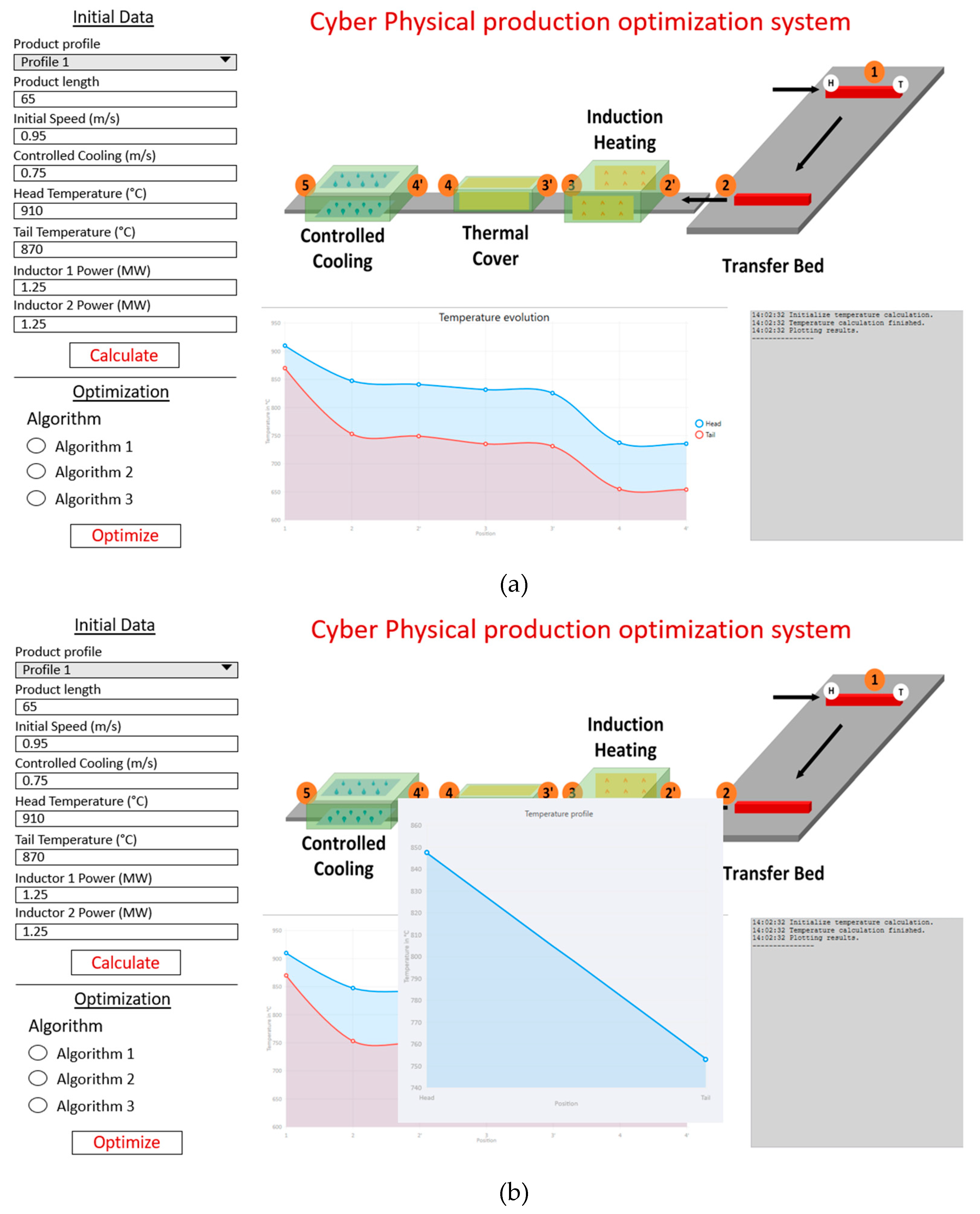
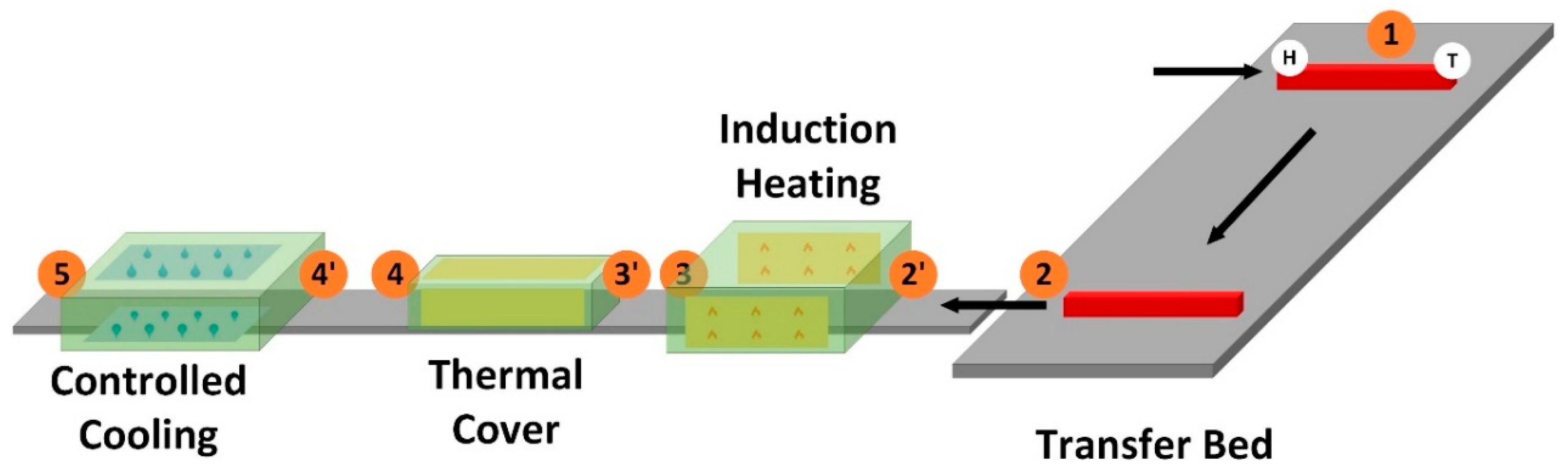
4.1. Induction-Heating System Optimization

The goal is to achieve a homogeneous temperature distribution over the long product’s length for optimizing the product quality as already described in Section 2.4. In this case, this is targeted by optimizing the induction heating process between the transfer bed and the cooling section. A product-specific, linearly increasing, power ramp is currently employed and should be continuously optimized by the CPPS depending on product and process specific parameters. This targets to improve the temperature gradient between head and tail of the product after the slowly moving transfer bed. Since the tail is heated at maximum, whereas the head is not heated at all. During the rest of the processing, the transport speed is higher than at the cooling stage, resulting in no further significant inhomogeneities of the temperature distribution. Subsequently, long products can be homogeneously cooled over the length in the active water-cooling section. The scheme of the induction heating system considered is reported in Figure 9. In deeper detail, the regarded process consists of the following main sub-processes, where pyrometer-based temperature measurements are labelled by numbers:
  • Transfer bed (1–2);
  • Transport section with air cooling (2–2′);
  • Induction furnace (2′–3);
  • Transport section with air cooling (3–3′);
  • Transport section covered by thermal insulator (3′–4);
  • Transport section with air cooling (4–4′);
  • Controlled cooling (4′–5).
Different thermo-process models must be considered between process steps. Therefore, different thermos-process models are integrated. For the transport section with air cooling or cover of a model based on the Newton’s law of cooling was considered based on convection. The finite element method (FEM) is used to calculate the thermal usable material condition. In this procedure, a physical object is divided into a finite number of elements to form a networked body. For each element of the computational mesh, which in turn can be described by nodes, the partial differential sliding can be solved by [30]:
ρ · c · T t ( t · λ · ) · T = q ˙ V
where c (J/(kg·K), ρ (kg/m3) and λ (W/m·K) are temperature-dependent material parameters, q ˙ V (W/m2) is the heat flux from each respective area of the product. Temperature (K) and time (s) are represented by T and t . A possible way to solve this approach in an online-applicable way can be found in [31]. In this way, the thermal state of the produced material can be determined by combining the individual partial results. It is possible to create a calculation model that is detached from the furnace condition, since thermal boundary conditions can be defined directly on the specific material. Furthermore, non-linear material parameters can be defined which depend on the material temperature. Thus, the thermal condition of the useful material can be described realistically. The execution of a calculation by means of FEM is divided into the following points:
  • Description of the geometry;
  • Generation of the computing network;
  • Definition of temperature-dependent material parameters;
  • Definition of the thermal boundary conditions;
  • Calculation of the thermal state of the useful material;
  • Visualization of the results.
This approach can be applied to arbitrary product geometries. It is not only possible to display the outer thermal state of the useful material but also any cross-section. Parameters have been thoroughly determined and approximated by real plant data and a good approximation of the temperature has been obtained.
Concerning product quality, the main relevant control parameter is the product’s through process temperature evolution. Main material properties are dependent on it. This usually concerns the trajectories of core and surface temperatures. These are determined by the material properties of the products in order to set specific material properties via the heating curve. Normally, these “recipes” have been developed and adapted by the industrial plant operators’ own departments over years and decades [32]. Therefore, a suitable possibility must be found to accommodate and consider these in the control and optimization. In qualitative terms, the recipe, i.e., the temperature curve of the surface temperature and core temperature, respectively, is fixed by often empirically determined metallurgical tests and experiences. These are necessary boundary conditions which are taken into account during optimization. The temperature sectors, possibly with certain tolerance ranges, must be reached. For the surface temperature, the tolerance range acts more as a limiting factor, which must not be exceeded, but should be exhausted to the maximum in order to optimize throughput.
For the induction heating, a model considering the effect of the initial temperature and the effect of the power/energy in the working volume was considered A simplified temperature calculation can be performed based on the determined Nagaoka coefficient. As a function of time, the unified cross-sectional temperature can be calculated according to the following formula [33]:
T i + 1 =   T i + Δ t C p , i · [ 1 σ i · ( σ i ω i 0 , 5 ) 2 · ϵ R · ( 1 + R l ) · ( T i 4 1 ) ]
where C p , i (-) is the specific heat capacity factor, Δ t the time between temperature steps, and normalized σ i , ϵ R further temperature dependent process parameters (entry depth of eddy currents, emissivity) as well as geometrical parameters R l , ω i (radius product/length of inductor, number of windings). The parameters are empirically determined with plant measurements. This procedure benefits from the fact that, in addition to the temperature-dependent material parameters, it also includes the radiation loss due to heat radiation. If the inductive heating should be carried out with a low frequency, this equation can be used, because with a high penetration depth of the eddy currents, an approximately homogeneous heating takes place. With this formula it is not necessary to solve the underlying differential equation system, which saves computing time. This is a practicable approach especially for time-critical applications. The power of the inductors P i is implicitly included within σ i . The Equation (3) is only used for the calculation of cylindrical geometries. The calculation of other objects requires the implementation of specific different models. At this point, the use of a geometry independent model is desirable. One possibility is to use the equations of Maxwell. Based on simple information regarding the geometry and depending plant parameters, the resulting eddy currents can be determined. The occurring resistance heating leads to a heat flux inside of the object, which can be used to calculate the cross-sectional temperature with the already developed model of Equation (2).
For this use case we considered an induction heating system composed of two inductors, the waiting time at point 2 was neglected and speed between the point 2 and 4′ was considered constant. The aim was to reach the point 4’ at an objective temperature within certain margin of error (e.g., ±10 °C), the same for the whole rail length and with an equal distribution of the power between the two inductors. The non-linear constrained optimization problem can be formalized as follows:
m i n E = 1 2 ( T ( 4 ) T ( 4 ) ¯ ) 2 s u b j e c t   t o 0 P 1 P m a x 0 P 2 P m a x P 1 = P 2
where T ( 4 ) is the temperature at point 4′, T ( 4 ) ¯ is the desired temperature at point 4′, P 1 and P 2 are inductors for power (W) and P m a x the maximum power (W) of the inductors. The problem can be divided into 2 sub-problems, one for the tail of the product and one for the head of the product but, due to the previous considerations about the head and the tail of the product, the induction system works mainly on the tail part, so only one problem has to be solved.
The tests have been performed in the MATLAB environment and compared to the results obtained through the developed optimization module. Two optimization algorithms have been tested, penalty method and genetic algorithms. Since the penalty method is not implemented in the MATLAB environment, the barrier method [25] has been selected being similar for some aspects to the penalty method. Typical process parameters have been considered for the tests. The optimization results are summarized in Table 1. The results obtained through both MATLAB and the optimization module are similar. All the algorithms found a solution that complies with the problem constraints with a null or a negligible error, i.e., the desired temperature is reached. The time needed to solve the problem depends on the algorithm options. Sometimes it can be more time-consuming, for this reason the algorithms have been run several times and the best score has been considered. Therefore, it is not possible to establish which approach is better. However, optimization is out of the scope of the present paper, which is focused on the design of CPS. Further tests will be developed in the future by exploiting the described platform on different processes, which will allow assessing the potentials, advantages and drawbacks of the different optimization approaches.

4.2. Setup Strategy for the Cyber-Physucal Production Optimization Systems

In order to test the application-oriented part of the CPPS platform in an industrial perspective, the general automation infrastructure depicted in Figure 10 has been considered. At base level, there are sensors and actuators connected to the physical processes. The middle level is devoted to the control and supervisory control of the processes through Programmable Logic Controllers (PLCs) and Industrial Personal Computers (IPCs), while the top level is dedicated to monitoring, optimization and data acquisition tasks. This scheme has been derived according to the International Society of Automation’s ISA-95 standard [34].
Figure 11 shows an example of CPPS platform modules deployment and consequently how the communication among the main actors of the automation system for the through process optimization takes place. Here, the IPC/PLC requests to the engineering station, the optimization of the process parameters, e.g., the products temperature profile, based on the process target properties desired. On the engineering station both CPS models and the optimization module are deployed. The CPS models are used for the simulation of the processes and they are the input for the optimization module that runs the optimization algorithms described in Section 2. The results of the optimization are the control parameters (e.g., the inductors power) to be used for the process optimization. The results are stored into the database connected to the local industrial network and accessible to the IPCs/PLCs. The setup of the CPS models and the optimization module on the engineering station described above is only an example. It can be considered as the first approach. Another approach consists in deploying the optimization module on a PC located in the cloud and leaving the CPS models on the engineering station. In this case, a communication between the engineering station and the external PC is necessary. Furthermore, the optimization results could be directly stored by the external PC on the local database or communicated and sent to the engineering station.

5. Conclusions

Industry 4.0 makes use of CPS technology to build CPPS. CPPS leads to a smart factory concept that offers advantages regarding quality, time and costs in comparison with classical production systems. This paper presents a new simulation framework for the design of CPPS in the context of intelligent steel manufacturing. A transferable model-based CPPS platform for long production facilities focused on thermal evolution and related material quality has been implemented. The platform combines physical models (thermal, rolling, transport), material-quality models, logistics/scheduling models with communication models (computers, software, networks); it includes strategies and methods for through process optimization as well as a cyber-physical library for the “drag-and-drop” implementation of CPPS. Simulation results show how the proper connection between models and communication and optimization methods lead to improved product quality establishing the feasibility, safety and benefits of cyber-physical production systems in the context of Industry 4.0. Furthermore, the flexibility of the IT software architecture implemented allows the transferability to any steel production line with low effort. Future work will deal with the integration, validation and test of the platform within the steel industrial facilities as well as on the assessment of the performances of different optimization approaches. Moreover, a cloud implementation of the platform will be investigated.

Author Contributions

Conceptualization, J.D., V.I. and V.C.; data curation, M.G. and V.I.; formal analysis, J.D., M.G., V.I. and V.C.; funding acquisition, V.C. and J.D.; investigation, J.D., M.G. and V.I.; methodology, J.D., M.G. and V.I.; project administration, J.D. and V.C.; resources, J.D., M.G. and V.I.; software, M.G. and V.I.; supervision, V.C.; validation, V.I. and M.G.; visualization, V.I., J.D. and M.G.; writing—original draft preparation, V.I.; writing—review and editing, J.D. and V.C.

Funding

The research described in the present paper was developed within the project entitled “Virtual Design of Cyber-Physical Production Optimization Systems for Long Production Factories” and was funded by Research Fund for Coal and Steel of the European Union, Grant Agreement No 709669.

Acknowledgments

The sole responsibility of the issues treated in the present paper lies with the authors; the Commission is not responsible for any use that may be made of the information contained therein. The authors wish to acknowledge with thanks the European Union for the opportunity granted that has made possible the development of the present work. The authors also wish to thank all partners of the project for their support and the fruitful discussion that led to successful completion of the present work.

Conflicts of Interest

The authors declare no conflict of interest.

References

  1. European Commission. Report from the Commission to the European Parliament, the Council, the European Economic and Social Committee and the Committee of the Regions. Available online: https://ec.europa.eu/transparency/regdoc/rep/10102/2019/EN/SWD-2019-1-F1-EN-MAIN-PART-4.PDF (accessed on 23 July 2019).
  2. Biondi, M.; Saliba, S.; Harjunkoski, J. Production Optimization and Scheduling in a Steel Plant: Hot Rolling Mill. IFAC Proc. Vol. 2011, 44, 11750–11754. [Google Scholar] [CrossRef]
  3. Polzer, J.; Denker, J.; Hartman, H.G.; Lupinelli, M.; Martini, F.; Nastasi, G. Technology-Based Assistance System for Production Planning in Stainless Mills; European Union: Brussels, Belgium, 2015; ISBN 978-92-79-55072-0. [Google Scholar]
  4. Ema, L.; Peregrina, S.; Dischinger, N.; Queck, A.; Tavassi, M.; Murri, M.; Caporusso, R.A.; de la Fuente, D.; Helo, P. Optimisation of Stocks Management and Production Scheduling by Simulation of the Continuous Casting, Rolling and Finishing Departments; European Union: Brussels, Belgium, 2011; ISBN 978-92-79-20895-9. [Google Scholar]
  5. Yang, J.; Wang, B.; Zou, C.; Li, X.; Li, T.; Liu, Q. Optimal Charge Planning Model of Steelmaking Based on Multi-Objective Evolutionary Algorithm. Metals 2018, 8, 483. [Google Scholar] [CrossRef]
  6. Costa, P.; Altamirano, G.; Salinas, A.; González-González, D.S.; Goodwin, F. Optimization of the Continuous Galvanizing Heat Treatment Process in Ultra-High Strength Dual Phase Steels Using a Multivariate Model. Metals 2019, 9, 703. [Google Scholar] [CrossRef]
  7. Lee, A.; Seshia, A. Introduction to Embedded Systems, a Cyber-Physical Systems Approach, 2nd ed.; MIT Press: Cambridge, MA, USA, 2017; ISBN 978-0-262-53381-2. [Google Scholar]
  8. European Commission. Report from the Workshop on Cyber-Physical Systems: Uplifting Europe’s Innovation Capacity. Available online: http://ec.europa.eu/information_society/newsroom/cf/dae/document.cfm?doc_id=3948 (accessed on 22 July 2019).
  9. Monostori, L. Cyber-Physical Production Systems: Roots, Expectations and R&D Challenges. Procedia CIRP 2014, 17, 9–13. [Google Scholar]
  10. Engell, S.; Paulen, R.; Reniers, M.A.; Sonntag, C.; Thompson, H. Core Research and Innovation Areas in Cyber-Physical Systems of Systems. In Cyber Physical Systems. Design, Modeling, and Evaluation; Mousavi, M., Berger, C., Eds.; Springer: Cham, Switzerland, 2015; Volume 9361, ISBN 978-3-319-25140-0. [Google Scholar] [CrossRef]
  11. Leitão, P.; Barbosa, J.; Papadopoulou, M.E.; Venieris, I.S. Standardization in Cyber-Physical Systems: The ARUM Case. In Proceedings of the IEEE International Conference on Industrial Technology (ICIT), Seville, Spain, 17–19 March 2015; pp. 2988–2993. [Google Scholar] [CrossRef]
  12. acatech. Cyber Physical Systems—Driving force for innovation in mobility, health, energy and production. In Acatech POSITION PAPER; acatech, Ed.; Springer: Berlin, Germany, 2011; ISBN 978-3-642-29089-3. [Google Scholar] [CrossRef]
  13. Sun, J.; Peng, W.; Ding, J.; Li, X.; Zhang, D. Key Intelligent Technology of Steel Strip Production through Process. Metals 2018, 8, 597. [Google Scholar] [CrossRef]
  14. Iannino, V.; Vannocci, M.; Vannucci, M.; Colla, V.; Neuer, M. A Multi-Agent Approach for the Self-Optimization of Steel Production. Int. J. Simul. Syst. Sci. Technol. 2018, 19, 20:1–20:6. [Google Scholar] [CrossRef]
  15. Ebel, A.; Neuer, M.; Matskanis, N.; Mouton, S.; Marchiori, F.; Pietrosanti, C.; Papiez, A.; Rößiger, M.; Goldenberg, N.; Mathis, G.; et al. Integrated Intelligent Manufacturing for Steel Industries; European Union: Brussels, Belgium, 2017; ISBN 978-92-79-65607-1. [Google Scholar]
  16. Hoffmann, M.; Kreisköther, K.; Büscher, C.; Meisen, T.; Kampker, A.; Schilberg, D.; Jeschke, S. Optimized Factory Planning and Process Chain Formation Using Virtual Production Intelligence. In Enabling Manufacturing Competitiveness and Economic Sustainability; Zaeh, M., Ed.; Springer: Cham, Switzerland, 2014; pp. 153–158. ISBN 978-3-319-02053-2. [Google Scholar] [CrossRef]
  17. Arnu, D.; Yaqub, E.; Mocci, C.; Colla, V.; Neuer, M.; Fricout, G.; Renard, X.; Mozzati, C.; Gallinari, P. A Reference Architecture for Quality Improvement in Steel Production. In Data Science—Analytics and Applications; Haber, P., Lampoltshammer, T., Mayr, M., Eds.; Springer Vieweg: Wiesbaden, Germany, 2017; pp. 85–90. ISBN 978-3-658-19286-0. [Google Scholar]
  18. Shardt, Y.A.W.; Mehrkanoon, S.; Zhang, K.; Yang, X.; Suykens, J.; Ding, S.X.; Peng, K. Modelling the strip thickness in hot steel rolling mills using least-squares support vector machines. Can. J. Chem. Eng. 2018, 96, 171–178. [Google Scholar] [CrossRef]
  19. Delange, J.; Feiler, P. Incremental latency analysis of heterogeneous cyber-physical systems. In Proceedings of the 3rd IEEE International Workshop on Real-Time and Distributed Computing in Emerging Applications (RTSS), Rome, Italy, 2 December 2014. [Google Scholar]
  20. European Computer Manufacturers Association (ECMA). Standard ECMA-335: Common Language Infrastructure (CLI). Available online: https://www.ecma-international.org/publications/files/ECMA-ST/ECMA-335.pdf (accessed on 23 July 2019).
  21. Intel. Intel Math Kernel Library. Available online: https://software.intel.com/en-us/mkl (accessed on 23 July 2019).
  22. Fielding, R.T. Architectural Styles and the Design of Network-Based Software Architectures. Ph.D. Thesis, University of California, Irvine, CA, USA, 2000. [Google Scholar]
  23. European Computer Manufacturers Association (ECMA). Standard ECMA-262: ECMAScript 2016 Language Specification. Available online: https://www.ecma-international.org/publications/files/ECMA-ST/Ecma-262.pdf (accessed on 23 July 2019).
  24. World Wide Web Consortium (W3C). Extensible Markup Language (XML) 1.0 (5th Edition). Available online: https://www.w3.org/TR/xml/ (accessed on 23 July 2019).
  25. Bazaraa, M.S.; Sherali, H.D.; Shetty, C.M. Nonlinear Programming: Theory and Algorithms, 3rd ed.; Wiley: Hoboken, NJ, USA, 2006; ISBN 978-0-471-48600-8. [Google Scholar]
  26. Nocedal, J.; Wright, S. Numerical Optimization, 2nd ed.; Springer: New York, NY, USA, 2006; ISBN 978-0-387-30303-1. [Google Scholar] [CrossRef]
  27. Yang, X.-S. Engineering Optimization: An Introduction with Metaheuristic Applications; Wiley: Hoboken, NJ, USA, 2010; ISBN 978-0-470-58246-6. [Google Scholar]
  28. Souza, C.R. The Accord.NET Framework. Available online: http://accord-framework.net (accessed on 23 July 2019).
  29. Giacomelli, D. GeneticSharp. Available online: https://github.com/giacomelli/GeneticSharp/ (accessed on 23 July 2019).
  30. Steinke, P. Finite-Elemente-Methode: Rechnergestützte Einführung, 5th ed.; Springer Vieweg: Wiesbaden, Germany, 2015. [Google Scholar]
  31. Denker, J.; Göttsche, M. Setup- and Furnace Control System for Hybrid Heating Systems for Flexibilizing and Improving Efficiency of the Process Industry (SmartHeating); Project Funded by EU and EFRE (Europäischer Fonds für Regionale Entwicklung); EU: Brussels, Belgium; EFRE: Brussels, Belgium, 2018. [Google Scholar]
  32. Steinböck, A. Model-Based Control and Optimization of a Continuous Slab Reheating Furnace; Shaker Verlag: Herzogenrath, Germany, 2011. [Google Scholar]
  33. Jankowski, T.A.; Pawley, N.H.; Gonzales, L.M.; Ross, C.A.; Jurney, J.D. Approximate analytical solution for induction heating of solid cylinders. Appl. Math. Model. 2016, 40, 2770–2782. [Google Scholar] [CrossRef]
  34. International Society of Automation ISA-95, Enterprise Control System Integration. Available online: https://www.isa.org/isa95/ (accessed on 23 July 2019).
Figure 1. Exemplar manufacturing process of long products.
Metals 09 01025 g001
Figure 2. Virtual design of a Cyber-Physical Production System (CPPS), showing coherences between modules.
Metals 09 01025 g002
Figure 3. Detailed view of a platform module.
Metals 09 01025 g003
Figure 4. Example of prototypical “drag-and-drop” graphical user interface.
Metals 09 01025 g004
Figure 5. Exemplary layout of overall material definition.
Metals 09 01025 g005
Figure 6. Exemplary layout of process step to be parametrized.
Metals 09 01025 g006
Figure 7. Optimization library classes scheme.
Metals 09 01025 g007
Figure 8. (a) Exemplary extract of HMI module for the CPPS; (b) exemplary extract of HMI module for the CPPS with current temperature profile at process stage’s entry 2.
Metals 09 01025 g008
Figure 9. General scheme for considered induction heating optimization within CPPS.
Metals 09 01025 g009
Figure 10. General scheme of an automation system with cloud connection.
Metals 09 01025 g010
Figure 11. Communication among the main actors of automation system for the optimization purposes.
Metals 09 01025 g011
Table 1. Results of the induction heating system optimization.
VariablesBarrier (MALAB)GA (MATLAB)Penalty (Opt. Module)GA (Opt. Module)
P 1 0.44160.44140.44160.4416
P 2 0.44160.44180.44160.4416
E 0000.004
E x e c u t i o n   T i m e   ( s ) 0.110.180.040.06

