Microstructure and Properties of Hybrid Laser Arc Welded Joints (Laser Beam-MAG) in Thermo-Mechanical Control Processed S700MC Steel


Abstract
:1. Introduction
2. Experimental Section
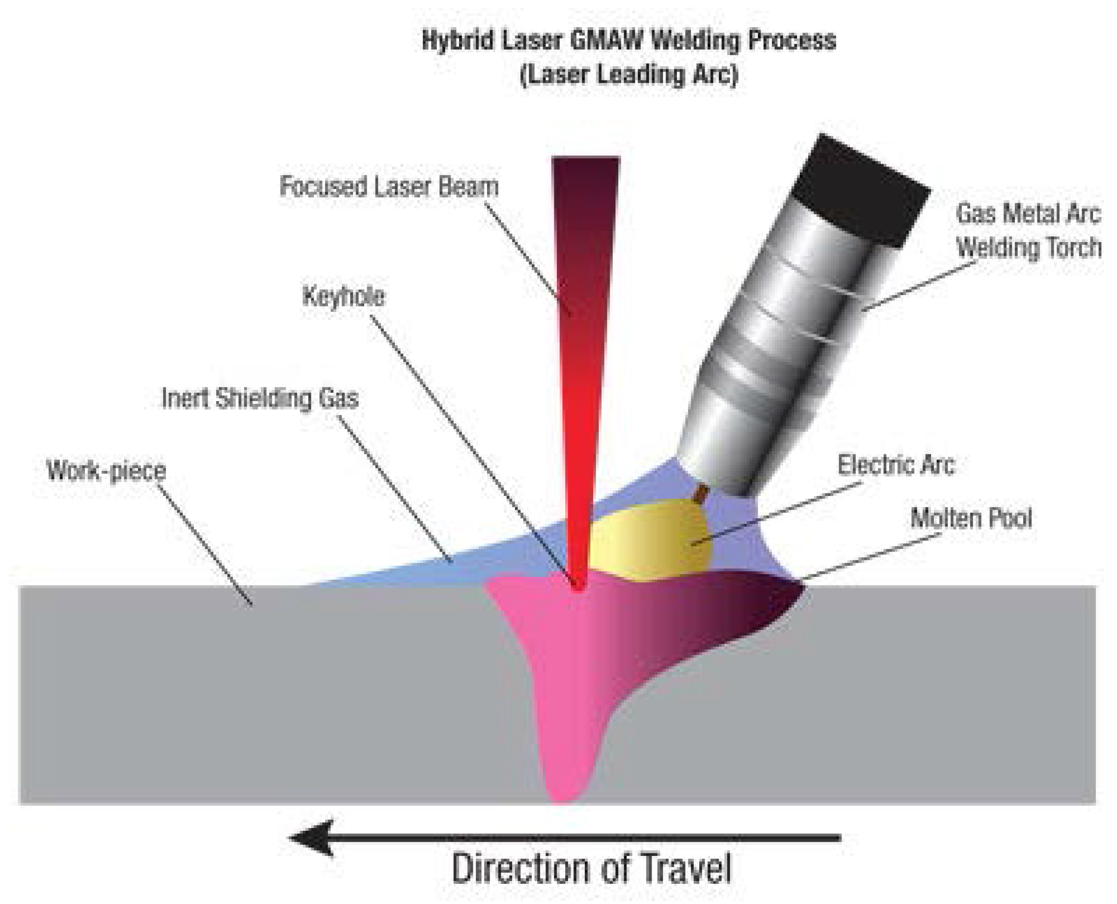
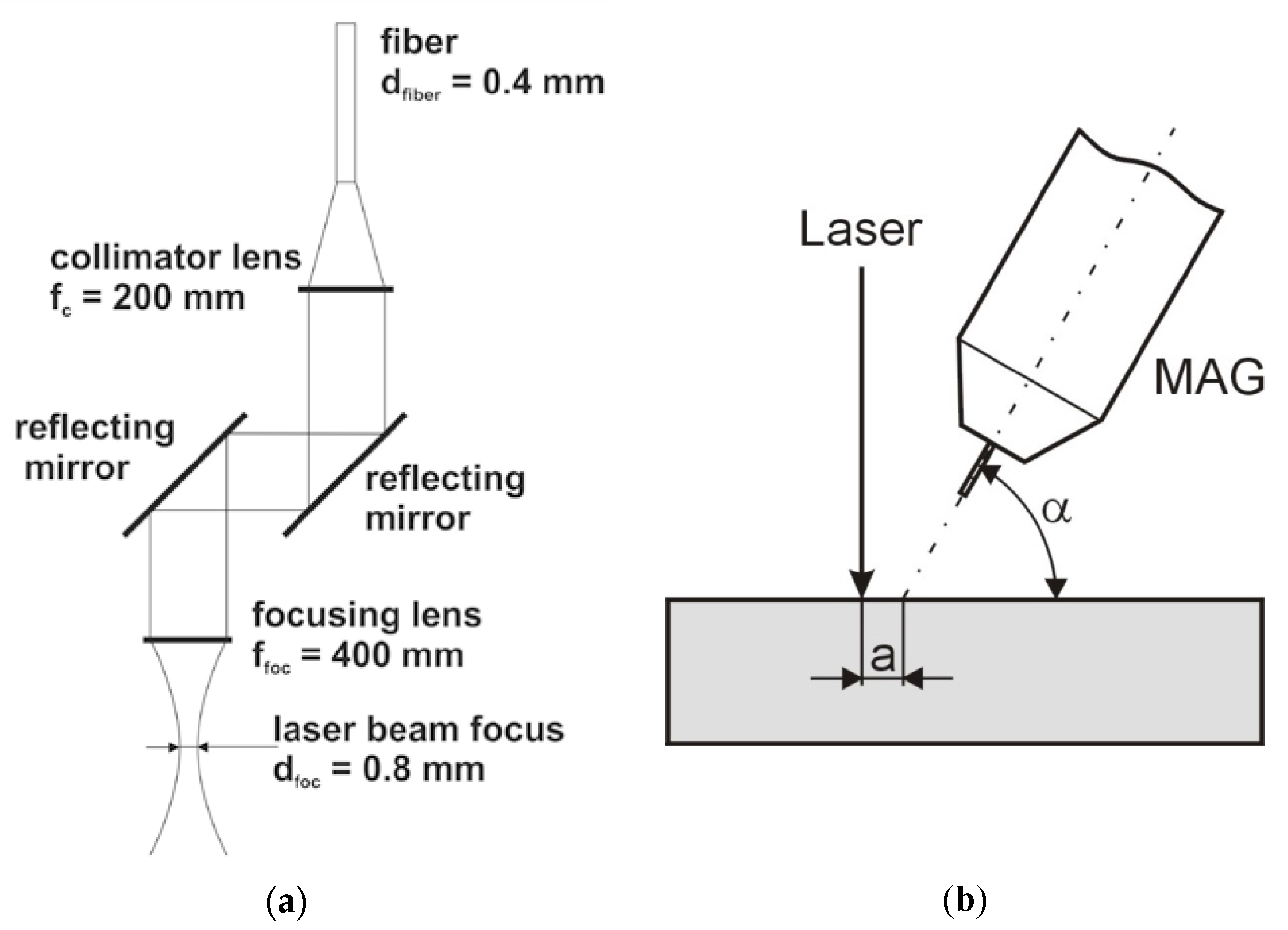
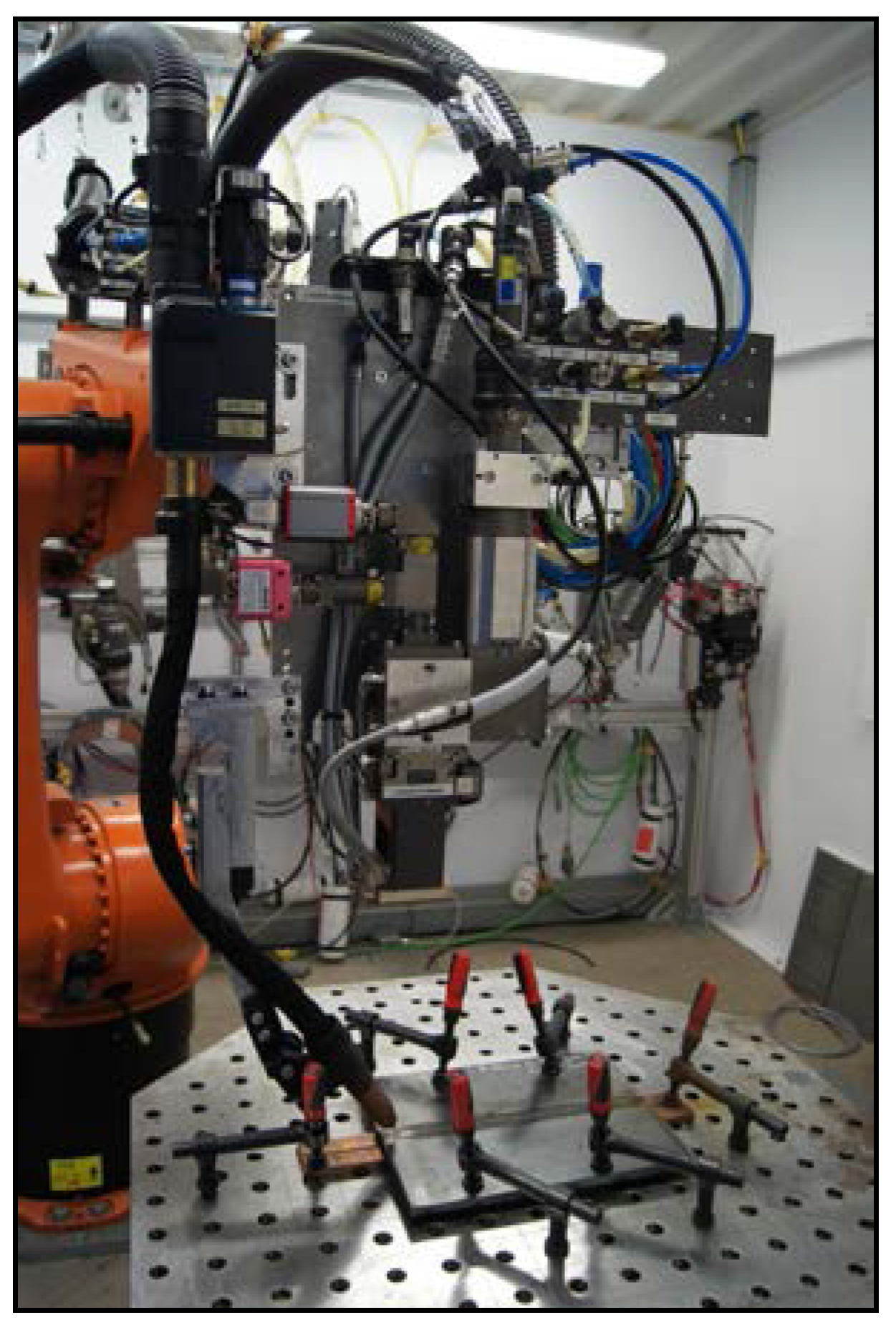
2.1. Welding Process
2.2. Tests of Welded Joints
- visual tests performed on the basis of the requirements specified in the PN-EN ISO 17637:2011 standard;
- magnetic particle tests performed following the guidelines referred to in the PN-EN ISO 3059:2005, PN-EN ISO 9934-2:2003, and PN-EN ISO 9934-3:2003 standards. The necessary contrast was obtained using white contrast paint MR 72. The tests were performed using magnetic powder suspension MR 76S (MR International, Fränkisch-Crumbach, Germany) and a yoke electromagnet;
- radiographic tests based on the PN-EN 1435 standard performed using a CERAM 235 X-ray tube (Balteau NDT, Hermalle-sous-argenteau, Belgium) with the X-ray beam having a diameter d = 2 mm, a voltage U = 180 kV, a current I = 3 mA, and intensifying screens OW of −0.15 mm. The test results were recorded using an AGFA C5 photographic plate with an exposure time t = 2.3 min and a focal length f = 700 mm. Images were assessed using a 13FEEN wire-type image quality indicator.
- tensile tests performed in accordance with PN-EN ISO 6892-1:2010 using a ZWICK/ROELL Z 330RED (Zwick Roell, Ulm, Germany) testing machine and specimens sampled in accordance with PN-EN ISO 4136:2011 (dimensions of the sample: 300 mm × 35 mm × 10 mm);
- a face bend test of the butt weld (FBB) and a root bend test of the butt weld (RBB) performed in accordance with the PN-EN ISO 5173:2010 standard (dimensions of the sample: 300 mm × 20 mm × 10 mm). The bend tests were performed using a ZWICK/ROELL Z 330RED testing machine (Zwick Roell, Ulm, Germany) with an additional module enabling the performance of bend tests involving the use of a bending mandrel having a diameter of 30 mm. The distance between the rollers was set at 60 mm. To identify the position of the weld axis, the faces of the specimens were etched using Adler’s reagent;
- impact strength tests performed in accordance with PN-EN ISO 148-1:2010 using specimens with the V-notch and a ZWICK/ROELL RKP 450 impact testing machine (Zwick Roell, Ulm, Germany). The tests were conducted at a temperature of −30 °C (due to industrial requirements). Because of the thickness of the plates being welded (10 mm) and the necessity of performing a preparatory mechanical treatment, the specimens were reduced in cross-section to 7.5 mm. The samples were extracted from the base metal, the heat-affected zone (HAZ), and the FL (fusion line), and the specimens were etched using Nital;
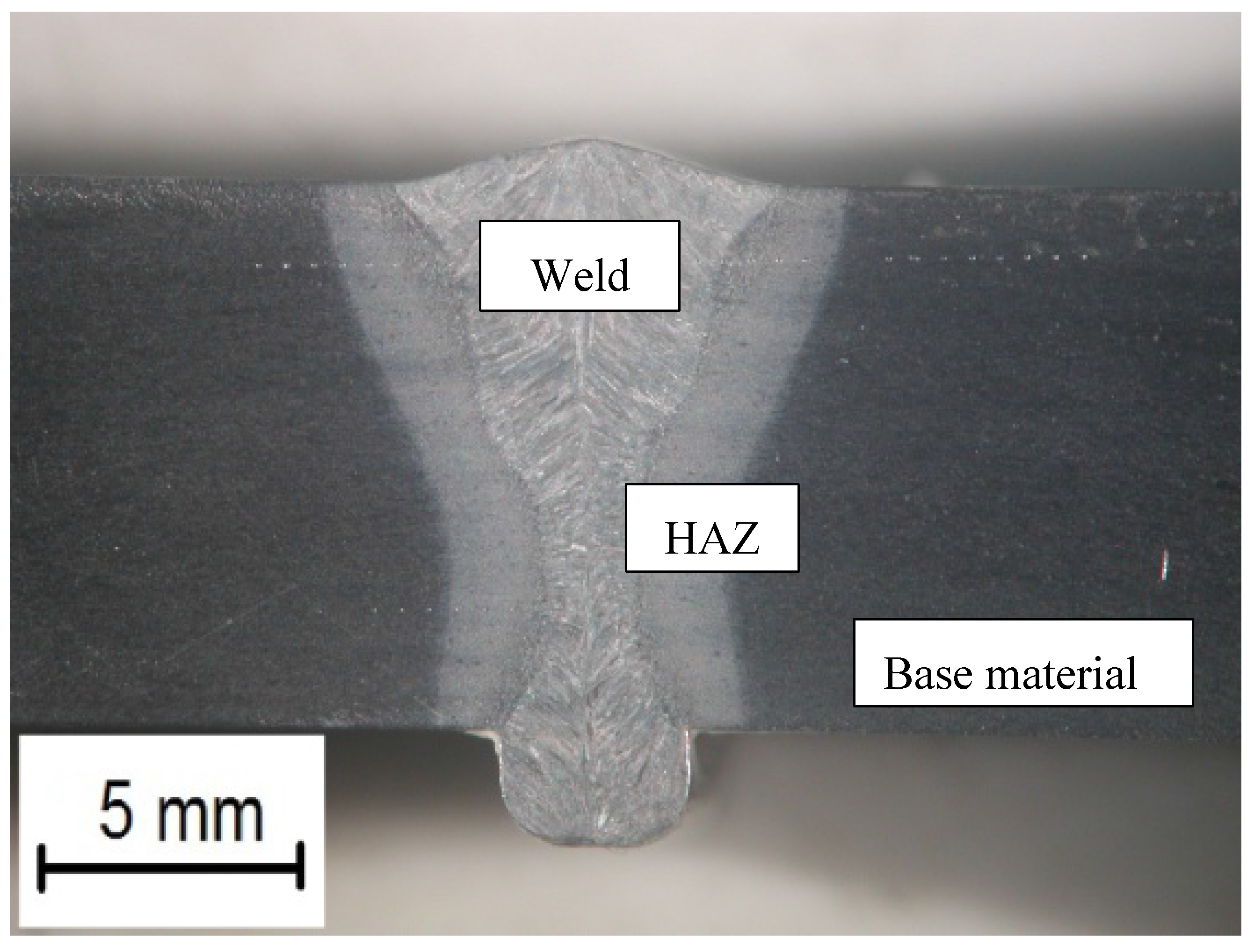
- macroscopic metallographic tests performed using an Olympus SZX9 light stereoscopic microscope (Olympus, Tokyo, Japan); the test specimens were etched using Adler’s reagent (CHMES, Poznań, Poland);
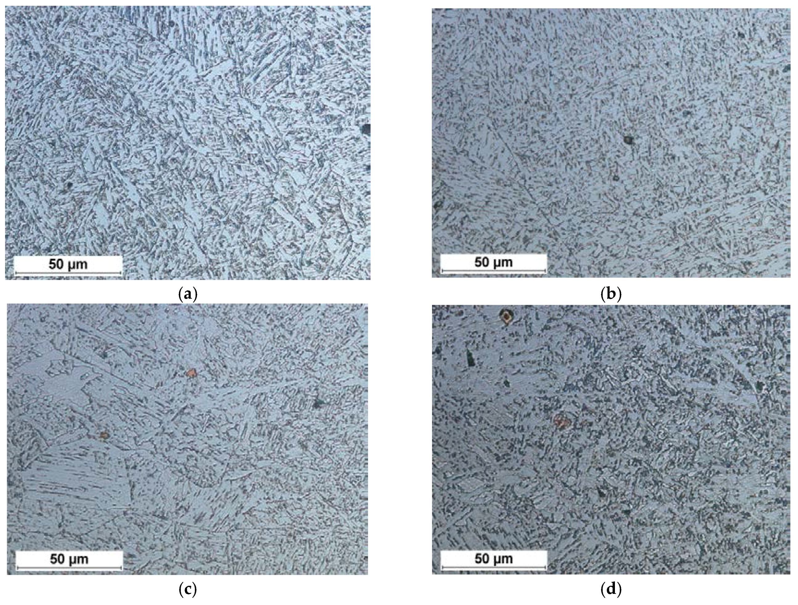
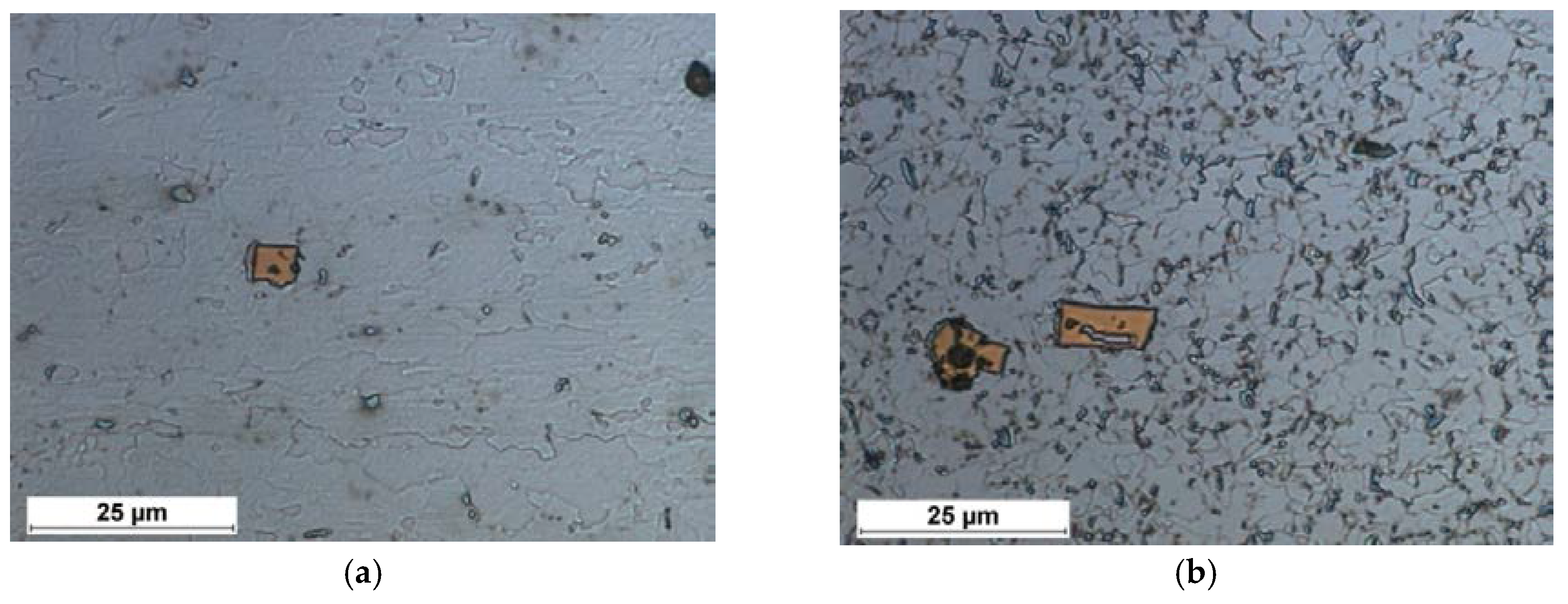
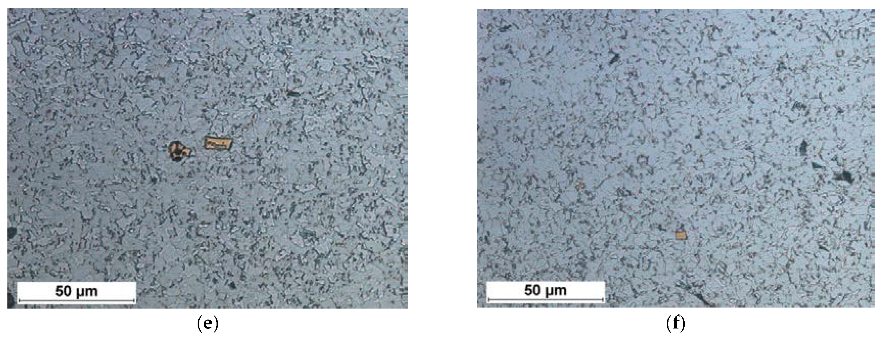
- microscopic metallographic tests performed using a NIKON ECLIPSE MA100 light microscope (Nikon, Tokyo, Japan); the test specimens were etched using Nital;
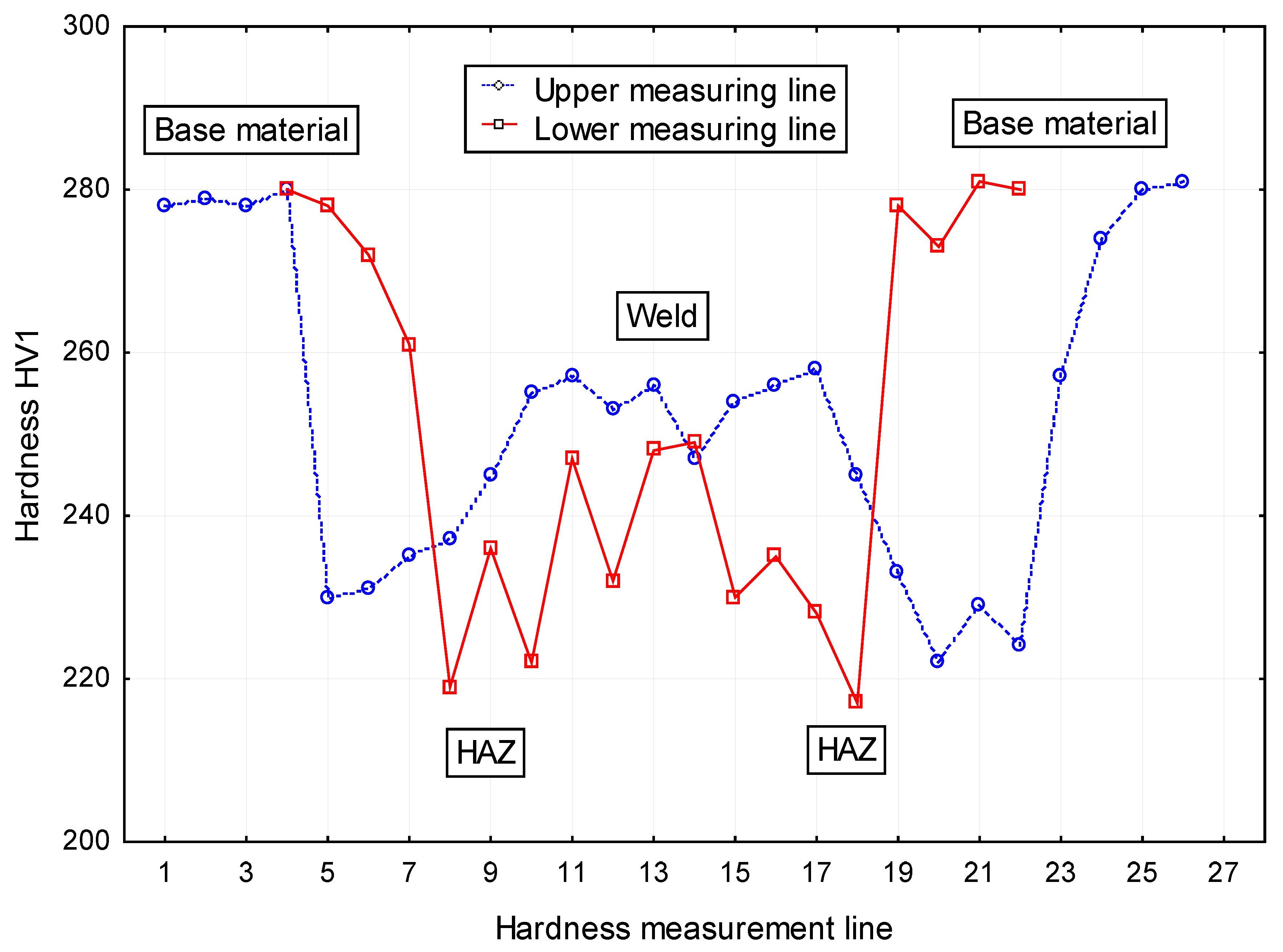
- hardness measurements performed using a Vickers 401MVD hardness testing machine (Wilson Wolpert, Norwood, Massachusetts, USA) and a load of 1 kg;
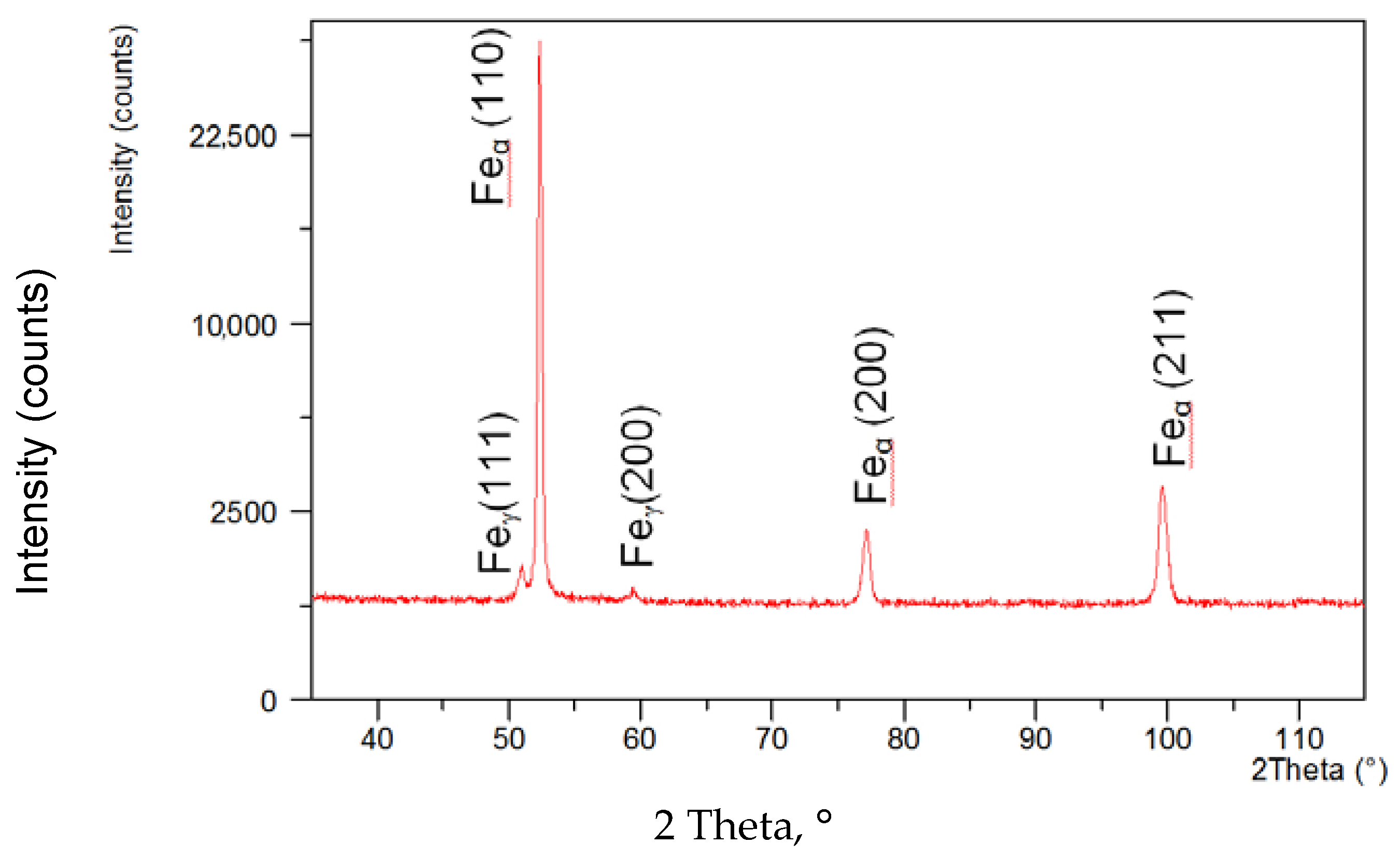
- X-ray phase analysis performed using an X’Pert PRO diffractometer and an X’Celerator strip detector (PANalytical, Almelo, The Netherlands);
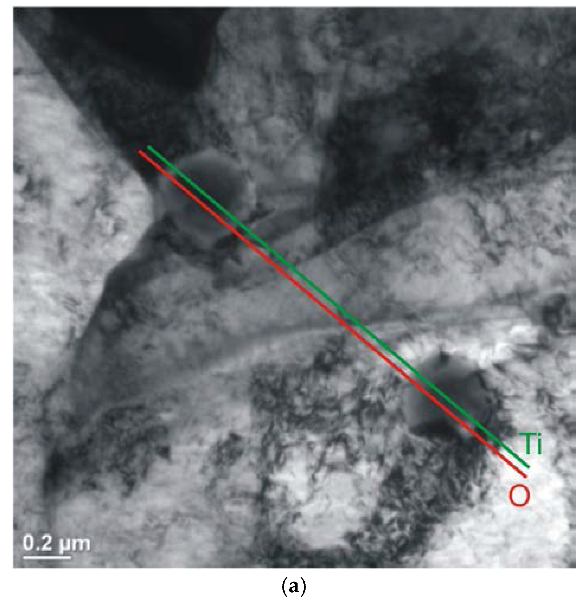
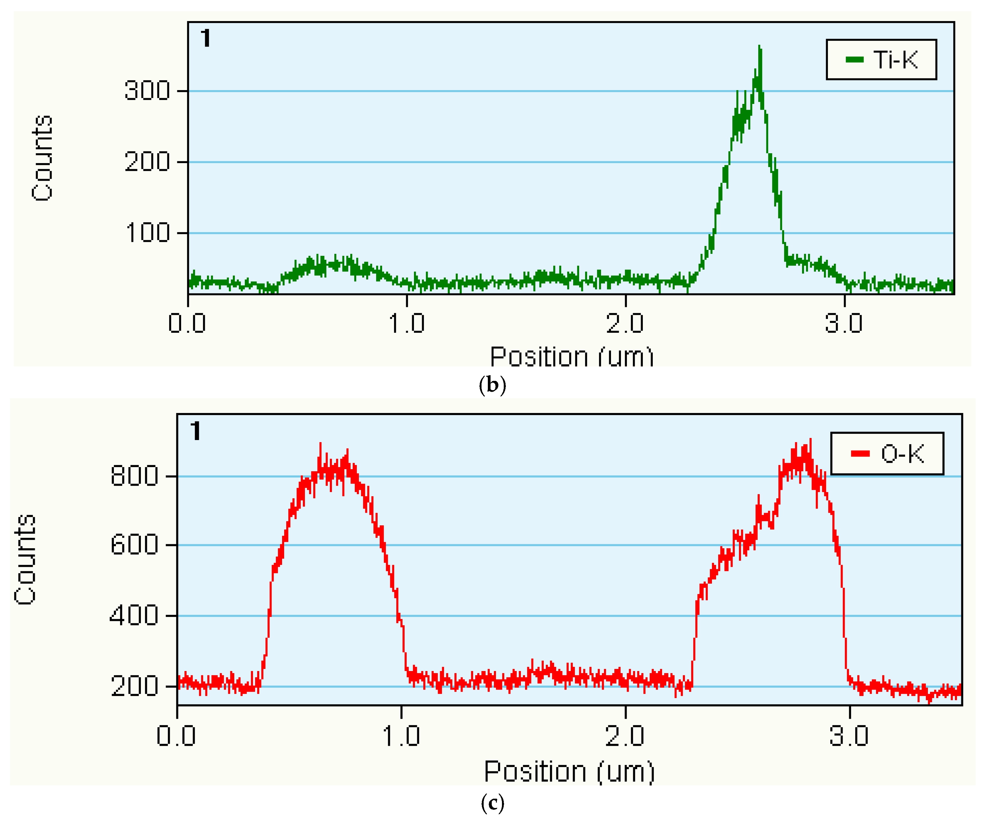
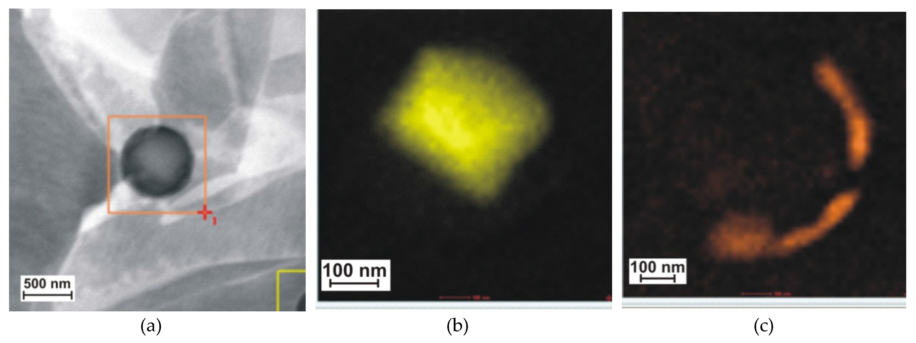
- tests of thin foils performed using a Titan 80–300 kV (FEI) high-resolution scanning transmission electron microscope (HR S/TEM, Thermo Fisher Scientific, Waltham, MA, USA) provided with an XFEG electron gun with the Schottky field emission characterised by enhanced brightness.
3. Results and Discussion
4. Conclusions
Acknowledgments
Author Contributions
Conflicts of Interest
References
- Flaxa, V.; Shaw, J. Material applications in ULSAB-AVC. Steel Grips 2003, 1, 255–261. [Google Scholar]
- Opiela, M. Thermodynamic analysis of the precipitation of carbonitrides in microalloyed steels. Mater. Tehnol. 2015, 49, 395–401. [Google Scholar] [CrossRef]
- Opiela, M. Elaboration of thermomechanical treatment conditions of Ti-V and Ti-Nb-V microalloyed forging steels. Arch. Metall. Mater. 2014, 59, 1181–1188. [Google Scholar] [CrossRef]
- Grajcar, A. Thermodynamic analysis of precipitation processes in Nb-Ti-microalloyed Si-Al TRIP steel. J. Therm. Anal. Calorim. 2014, 118, 1011–1020. [Google Scholar] [CrossRef]
- Mikia, C.; Homma, K.; Tominaga, T. High strength and high performance steels and their use in bridge structures. J. Constr. Steel Res. 2002, 58, 3–20. [Google Scholar] [CrossRef]
- Lee, C.; Shin, H.; Park, K. Evaluation of high strength TMCP steel weld for use in cold regions. J. Constr. Steel Res. 2012, 74, 134–139. [Google Scholar] [CrossRef]
- Ollilainen, V.; Hurmola, H.; Pontinen, H. Mechanical properties and machinability of a high-strength, medium-carbon, microalloyed steel. J. Mater. Energy Syst. 1984, 5, 222–232. [Google Scholar] [CrossRef]
- Shipitsyn, S.; Babaskin, Y.; Kirchu, I.; Smolyakova, L.; Zolotar, N. Microalloyed steel for railroad wheels. Steel Transl. 2008, 38, 782–785. [Google Scholar] [CrossRef]
- Rak, I.; Gliha, V.; Kocak, M. Weldability and toughness assessment of Ti-microalloyed offshore steel. Metall. Mater. Trans. 1997, 28, 199–206. [Google Scholar] [CrossRef]
- Chang, K.; Lee, C.; Park, K.; Um, T. Experimental and numerical investigations on residual stresses in a multi-pass butt-welded high strength SM570-TMCP steel plate. Int. J. Steel Struct. 2011, 11, 315–324. [Google Scholar] [CrossRef]
- Nishioka, K.; Ichikawa, K. Progress in termomechanical control of steel plates and their commercialization. Sci. Technol. Adv. Mater. 2012, 13, 023001. [Google Scholar] [CrossRef] [PubMed]
- Grajcar, A.; Różański, M.; Kamińska, M.; Grzegorczyk, B. Effect of gas atmosphere on the non-metallic inclusions in laser-welded TRIP steel with Al and Si additions. Mater. Tehnol. 2016, 50, 945–950. [Google Scholar] [CrossRef]
- Żuk, M.; Górka, J.; Czupryński, A.; Adamiak, M. Properties and structure of the weld joints of quench and tempered 4330V steel. Metalurgija 2016, 55, 613–616. [Google Scholar]
- Górka, J. Microstructure and properties of the high-temperature (HAZ) of thermo-mechanically treated S700MC high-yield-strength steel. Mater. Tehnol./Mater. Technol. 2016, 50, 617–621. [Google Scholar] [CrossRef]
- Górka, J. Welding Thermal Cycle-Triggered Precipitation Processes in Steel S700MC Subjected to the Thermo-Mechanical Control Processing. Arch. Metall. Mater. 2017, 62, 331–336. [Google Scholar] [CrossRef]
- Burdzik, R.; Węgrzyn, T.; Konieczny, Ł.; Lisiecki, A. Research on influence of fatigue metal damage of the inner race of bearing on vibration in different frequencies. Arch. Metall. Mater. 2014, 59, 1275–1281. [Google Scholar] [CrossRef]
- Kurc-Lisiecka, A.; Piwnik, J.; Lisiecki, A. Laser welding of new grade of advanced high strength steel STRENX 1100 MC. Arch. Metall. Mater. 2017, 62, 1651–1657. [Google Scholar] [CrossRef]
- Górka, J.; Janicki, D.; Fidali, M.; Jamrozik, W. Thermographic Assessment of the HAZ Properties and Structure of Thermomechanically Treated Steel. Int. J. Thermophys. 2017, 38, 183. [Google Scholar] [CrossRef]
- Janicki, D.; Górka, J.; Kwaśny, W.; Gołombek, K.; Kondracki, M.; Żuk, M. Diode laser surface alloying of armor steel with tungsten carbide. Arch. Metall. Mater. 2017, 62, 473–481. [Google Scholar] [CrossRef]
- Grajcar, A.; Matter, P.; Stano, S.; Wilk, Z.; Różański, M. Microstructure and hardness profiles of bifocal laser-welded DP-HSLA steel overlap joints. J. Mater. Eng. Perform. 2017, 26, 1920–1928. [Google Scholar] [CrossRef]
- Grajcar, A.; Morawiec, M.; Różański, M.; Stano, S. Twin-spot laser welding of advanced high-strength multiphase microstructure steel. Opt. Laser Technol. 2017, 92, 52–61. [Google Scholar] [CrossRef]
- Kubiak, M.; Piekarska, W.; Stano, S.; Saternus, Z.; Domański, T. Numerical Prediction of Deformations in Laser Welded Sheets Made of X5CrNi18-10 Steel. Arch. Metall. Mater. 2015, 60, 1965–1972. [Google Scholar] [CrossRef]
- Naito, Y.; Katayama, S.; Matsunawa, A. Keyhole behaviour and liquid flow in molten pool during laser-arc hybrid welding. In Proceedings of the International Congress on Laser Advanced Materials Processing (LAMP 2002), Osaka, Japan, 27–31 May 2002; Volume 4831, pp. 357–363. [Google Scholar]
- Bagger, C.; Olsen, F. Comparison of plasma, metal inactive gas (MIG) and tungsten inactive gas (TIG) processes for laser hybrid welding. In Proceedings of the International Congress on Applications of Laser and Electro-Optics (ICALEO 2003), Jacksonville, FL, USA, 13–17 October 2003; pp. 11–20. [Google Scholar]
- Orozco, N.J. Fully integrated hybrid-laser welding control process, Processes for Laser Hybrid Welding. In Proceedings of the International Congress on Applications of Laser and Electro-Optics (ICALEO 2003), Jacksonville, FL, USA, 13–17 October 2003; pp. 31–40. [Google Scholar]
- Murakami, T.; Shin, M.H.; Nakata, K. Effect of welding direction on weld bead formation in high power fiber laser and MAG arc hybrid welding. Trans. JWRI 2010, 39, 175–177. [Google Scholar]
- Banasik, M.; Urbańczyk, M. Laser + MAG Hybrid Welding of Various Joints. Biul. Inst. Spaw. 2017. [Google Scholar] [CrossRef]
- Banasik, M.; Urbańczyk, M. Laser + MAG Hybrid Welding of T-Joints. Biul. Inst. Spaw. 2017. [Google Scholar] [CrossRef]
- Banasik, M.; Turyk, E.; Urbańczyk, M. Spawanie hybrydowe laser + MAG elementów urządzeń dźwigowych wykonanych ze stali ulepszonej cieplnie S960QL. Prz. Spaw. 2017, 89. [Google Scholar] [CrossRef]
- Wang, X.-N.; Zhang, S.-H.; Zhou, J.; Zhang, M.; Chen, C.-J.; Misra, R.D.K. Effect of heat input on microstructure and properties of hybrid fiber laser-arc weld joints of the 800 MPa hot-rolled Nb-Ti-Mo microalloyed steels. Opt. Lasers Eng. 2017, 91, 86–96. [Google Scholar] [CrossRef]
- Sun, Q.; Di, H.-S.; Li, J.-C.; Wu, B.-Q.; Misra, R.D.K. A comparative study of the microstructure and properties of 800MPa microalloyed C-Mn steel welded joints by laser and gas metal arc welding. Mater. Sci. Eng. A 2016, 669, 150–158. [Google Scholar] [CrossRef]
- Górka, J. Własności i Struktura Złączy Spawanych stali Obrabianej Termomechanicznie o Wysokiej Granicy Plastyczności; Wydawnictwo Politechniki Śląskiej: Gliwice, Poland, 2013. [Google Scholar]
- Górka, J.; Stano, S. The structure and properties of filler metal-free laser beam welded joints in steel S700MC subjected to TMCP. In Laser Technology 2016: Progress and Applications of Lasers; SPIE: Bellingham, WA, USA, 2016; Volume 10159, pp. 183–190. [Google Scholar]


| Chemical Composition, wt % | ||||||||||||
| C | Si | Mn | P | S | Altot. | Nb | V | Ti | B | Mo. | Ce ** | |
| 0.056 | 0.16 | 1.18 | 0.01 | 0.005 | 0.027 | 0.044 | 0.006 | 0.12 | 0.002 | 0.0150 | 0.33 | |
| Mechanical Properties | ||||||||||||
| Tensile Strength Rm, MPa | Yield Point Re, MPa | Elongation A5, % | Hardness HV | Impact strength, J/cm2 (−20 °C) | ||||||||
| 822 | 768 | 19 | 280 | 135 | ||||||||
| Chemical Composition, wt % | |||||||||
| C | Mn | Si | Cr | Ni | Mo | Ti | |||
| 0.1 | 1.8 | 0.7 | 0.3 | 2.0 | 0.55 | 0.07 | |||
| Mechanical Properties | |||||||||
| Tensile Strength Rm, MPa | Yield Point Re, MPa | Elongation A5, % | Impact Strength, J/cm2 (−40 °C) | ||||||
| 900 | 810 | 18 | 55 | ||||||
| Pre-Weld Metal Preparation | Welding Sequence | ||||
|---|---|---|---|---|---|
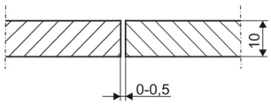 | 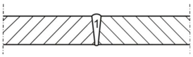 | ||||
| Beam Power, W | Welding Rate, m/min | Wire Feeding Rate, m/min | Welding Current, A | Arc Voltage, V | Width of the Gap, mm |
| 5000 | 0.7 | 8 | 250 | 22 | 0.7 |
| Tensile Strength * | Bending *, Bend Angle, ° | Impact Strength KCV **, J/cm2 (Test Temperature −30 °C) | ||||
|---|---|---|---|---|---|---|
| Rm, MPa | Area of Rupture | Face | Root | Weld | FL | HAZ |
| 790 | HAZ | 180 | 180 | 89 | 51 | 42 |
© 2018 by the authors. Licensee MDPI, Basel, Switzerland. This article is an open access article distributed under the terms and conditions of the Creative Commons Attribution (CC BY) license (http://creativecommons.org/licenses/by/4.0/).
Share and Cite
Górka, J.; Stano, S. Microstructure and Properties of Hybrid Laser Arc Welded Joints (Laser Beam-MAG) in Thermo-Mechanical Control Processed S700MC Steel. Metals 2018, 8, 132. https://doi.org/10.3390/met8020132
Górka J, Stano S. Microstructure and Properties of Hybrid Laser Arc Welded Joints (Laser Beam-MAG) in Thermo-Mechanical Control Processed S700MC Steel. Metals. 2018; 8(2):132. https://doi.org/10.3390/met8020132
Chicago/Turabian StyleGórka, Jacek, and Sebastian Stano. 2018. "Microstructure and Properties of Hybrid Laser Arc Welded Joints (Laser Beam-MAG) in Thermo-Mechanical Control Processed S700MC Steel" Metals 8, no. 2: 132. https://doi.org/10.3390/met8020132
APA StyleGórka, J., & Stano, S. (2018). Microstructure and Properties of Hybrid Laser Arc Welded Joints (Laser Beam-MAG) in Thermo-Mechanical Control Processed S700MC Steel. Metals, 8(2), 132. https://doi.org/10.3390/met8020132