Abstract
This paper investigates cutting force in thermal-assisted machining (TAM) by induction heating for SKD11 tool steel which is widely used in the mold industry. Experimental studies were first conducted at room and elevated temperatures to evaluate the effectiveness of the heating process on chip morphology and the cutting forces during the thermal-assisted machining and comparing with conventional machining method. The Taguchi method based on orthogonal array and analysis of variance ANOVA method was then used to design the number of experiments and evaluate the influence of cutting speed, feed rate, cutting depth, and elevated temperature on the cutting force. Study results showed a decrease in the cutting force in the TAM process. The optimal condition of parameters obtained for thermal-assisted machining were cutting speed 280 m/min, feed rate 230 mm/min, cutting depth 0.5 mm and temperature 400 °C. Finally, a proposed equation was established to determine the cutting force that was presented as a function of elevated temperatures when milling SKD11 material. A proposed cutting force model was compared, evaluated and confirmed to be in good agreement with experimental results.
1. Introduction
Thermal-assisted machining (TAM) is one of the new technology solutions for the continuous development of advanced materials that have high hardness, less resistance to wear and thermal conductivity. It supports the cutting process, improves the machinability of material, increases machining productivity, improves surface quality, and reduces product cost [1,2]. With TAM, metals are softened and hardness decreases [3]. Thereby, the machining process during elevated temperatures is easier than one during room temperature.
The manufacturing industry has developed various preheating technologies such as electrical resistance, oxyacetylene gas flame, laser-assisted machining (LAM), induction heating, plasma-enhanced machining (PEM), etc. In thermal-assisted machining, a blank is preheated with outside power to the material’s softening temperature. Then, it is machined by immediately using a normal machining method. Researchers [4,5,6,7] have studied various preheating methods for the machining process, and their benefits. However, each thermal-assisted method has different advantages and disadvantages and suitability for some machining methods. The induction preheating method is effective and inexpensive. It is a good choice for end milling with magnetic metals and alloys [8]. Sadeghipour K. et al. [9] used a finite element method to analyze the temperature distribution during induction heating by high frequency of steel (40–200 kHz). The simulation results showed good agreement when comparing with experimental data.
To test new technology solutions before their application to actual production, studying cutting forces is very important. In practice, the cutting forces are very important to the design of cutting tools, fixture, calculation, and design machine. Under effect of the cutting forces and cutting temperature, the tool will be worn or destroyed [10]. Ginta et al. [11] presented the effectiveness of thermal-assisted machining on machinability in end milling of Ti–6Al–V4 material. This study used an induction heating system. The research results concluded that direct heating of the blank before machining affected force cutting, chatter, tool life, and material removal rate. The cutting forces reduced in TAM. It made the decreasing stress on the tool, increasing tool life and reducing chatter in the cutting process. Baili et al. [2] studied thermal-assisted turning by induction heating to improve the machinability of Ti-5553. The research results also showed that the cutting forces reduced 34.4% when the blank’s temperature was 750 °C. However, the material structure could not be changed.
The aims of thermal-assisted machining are to reduce the material’s strength and the hardness of the blank. Therefore, the cutting force is reduced and chip morphology is changed. Sun et al. [12] researched chip formation during thermal-assisted machining by laser beam of Ti–6Al–V4 alloy. This study showed that chip formation was segmental with conventional machining, but beam power and cutting force were important in the process of transition from segmentation to continuous chip in LAM. Table 1 shows an analysis of previous studies during thermal-assisted machining. The effects of heating process on machinability have been analyzed in detail.

Table 1.
Summary of previous studies during thermal-assisted machining.
SKD11 tool steel is widely used in the automotive industry and mold manufacturing industry because of its great properties, such as its strength, ductility, and hardness being maintained at high temperatures [25]. Normally, SKD11 is machined using advanced methods such as grinding with abrasive diamond wheels or electro-discharge machining. However, these methods are limited because the tools are expensive and wear quickly; there is a low material removal rate, and so on. The cutting force, roughness, and wear were studied [25] to analyze the effect of high temperatures created by laser beam and compared with conventional machining methods. The research concluded that wear on tools was reduced, the cutting force decreased 40%, and roughness was reduced by up to 50% compared with machining at room temperature.
To investigate the effect of input parameters on the output experimental results, DoE (Design of Experiment) method has been well-known as a powerful tool which can upgrade/improve the performance of the product, process, design, and system with a significant slash in experimental time and cost [26,27]. The method is based on the mathematical statistics combined with the scientifically arrangement and evaluation of experiential data [27]. It has been used to apply to various research fields [28,29,30,31,32]. Where, the mean (ANOM) and variance (ANOVA) analysis is used to verify the effect of input parameters on the observation of interesting output. In order to minimize the tests and indicate the optimum levels of input parameters, the orthogonal array of DoE could be chosen from Taguchi’s standard orthogonal array table [33].
Recent research has concentrated on the effect of the thermal-assisted process on the output parameters of the cutting process: cutting force, surface roughness, tool wear, and chatter. The number of studies on the hot machining method with elevated temperatures heated by induction is still limited. So, this study looked at the effect of cutting parameters on cutting force in thermal-assisted milling of SKD11 steel by induction heating. The chip morphologies in conventional machining and TAM were compared and analyzed to predict the improvement of the cutting force and effectiveness of the thermal-assisted process. An experimental machining process was performed at room and elevated temperatures to find the optimum cutting and temperature parameters in order to minimize cutting force based on the Taguchi method. The relationship between cutting force and cutting parameters such as cutting speed, feed rate, and cutting depth were also simply constructed using the Gauss–Newton method in the nonlinear regression tool of Minitab17 software. However, the current study proposed a new method for predicting cutting force at different elevated temperatures. The prediction results were analyzed and compared, and were in good agreement with the experimental data.
2. Experimental Procedure
2.1. Material
Experimental studies were performed by machining SKD11 tool steel material. Table 2 and Table 3 show the chemical composition and material properties of the workpiece, which is widely used in the mold manufacturing industry [34]. To present the flow stress curves as the function of temperature, previous study [34] applied Johnson Cook’ flow stress model (J-C) and determined the (J-C) coefficients as shown in Table 3. Where A, B, C, n, and m are the material parameters to be identified, T (K) is the current temperature, Tm (K) is the melting temperature, and Tr is a reference temperature i.e., 298 (K), and are the equivalent plastic strain rate and the reference strain rate used for normalization, respectively.
Table 2.
Chemical compositions of SKD11 tool steel (%) [34].
Table 3.
Material properties and Johnson–Cook flow stress coefficient of SKD11 tool steel [35].
2.2. Experimental Setup
The experiments were conducted using an MC500 milling machine (Fuhong, Taichung City, Taiwan). A spindle speed of 100–30,000 r/min; spindle motor power of 15 kW; feed rate of 30,000 mm/min; maximum idle speed of 48,000 mm/min; and travel distances of the operating platform in X, Y, and Z axes of 500 mm, 400 mm, and 300 mm, respectively, were used. Cooling solution was not used during the machining process.
Figure 1 shows a photograph of the experimental setup for induction–assisted milling of SKD11 steel. The MC500 milling machine is illustrated by the spindle. The heat-assisted parts consist of magnetic induction power, frequency generator and induction coil. An experimental specimen of 70 mm × 31 mm × 80 mm was placed on the dynamometer with a clamp. Force measuring equipment was connected to a computer to display the measurement results. The researchers used an induction heating system to heat the workpiece to reach machining temperatures. The experiments used a three–component cutting force measurement device from Kistler in Switzerland that uses a piezoelectric force dynamometer (9257B, Kistler) with multi-component dynamometer up to 10 kN. The sensor sensitivity in the X, Y direction is 7.39 pC/N, and Z direction is 3.72 pC/N. DASYLab 10.0 software (DASYTec, Amherst, NH, USA) was used to convert A/D signals and save the data on a computer. A40 mm carbide insert milling tool diameter was used in the experiments. The APKT 1604PDR–GM cutting tool from Pramet in the Czech Republic was used with geometric parameters, as described in Figure 2 and Table 4.
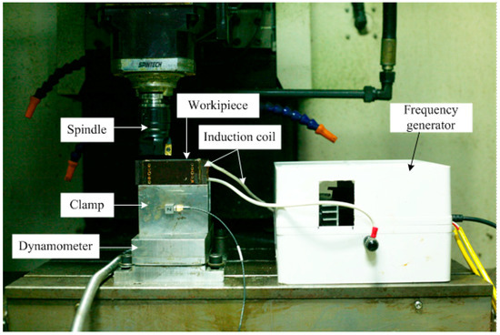
Figure 1.
Photograph of experimental setup for induction-assisted milling of SKD11 steel.
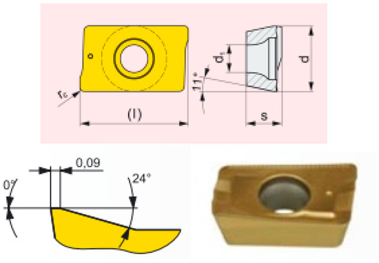
Figure 2.
APKT 1604PDR–GM cutting tool.
Table 4.
Geometric parameters of APKT 1604PDR–GM cutting tool.
To control the temperature which supports the machining process accurately and safely, the relationship between generated temperatures and heating times has been studied before cutting. A hand-held digital thermometer, model 3527A from TSURUGA corporation-Japan, had been used. During heating process, the thermometer was placed on the workpiece surface to measure the temperature based on heating time. A time-dependent temperature graph was constructed as shown in Figure 3. Three studied temperature levels of 200 °C, 300 °C, and 400 °C were achieved at 2, 3.8, and 6.3 min, respectively. Therefore, in order to verify the effect of temperature parameter on cutting force during the machining trials, the heating times have been utilized instead of measuring the elevated temperatures on the machining workpiece. Besides that, to evaluate the effect of heating process on material hardness, the initial workpiece and workpieces after preheating then air quenching at 200 °C, 300 °C, and 400 °C (Figure 4) were measured. Experimental results showed that the material hardness before and after preheating and air quenching were remained 250 HB.
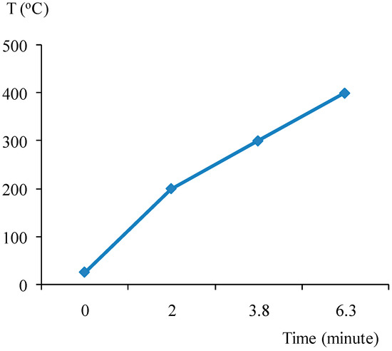
Figure 3.
The relationship between generated temperatures and heating times by using induction coil of SKD11 tool steel.
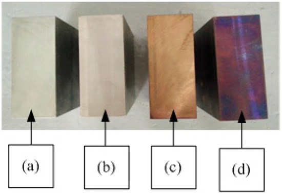
Figure 4.
The initial workpiece (a) and preheating workpieces of 200 °C (b), 300 °C (c), and 400 °C (d).
3. Design of Experiment
In this research, the Taguchi design of experiment (DoE) method [33] was chosen because of the objective optimization of control parameters and simple, effective, and economical number of experiments. In this method, each parameter can be evaluated individually and for random experiments with an orthogonal array (OA). The Taguchi method has the potential to narrow the scope of specific research or identify problems in production with existing data. In this method, the typical value for average performance that is close to the target value is appreciated more than a value with limited technical specifications [28,29,30,31,32].
The study identified four control parameters that had the biggest effect on cutting force, namely cutting speed (Vc), feed rate (f), cutting depth (t), and workpiece temperature at processing time (T). Measurement of the interactions between parameters was made with an S/N ratio. The S/N ratio was constructed with the following three objectives: larger is better, smaller is better, nominal is best.
This paper researched the influence of these control parameters on cutting force. Therefore, the smaller is better objective was chosen. The S/N ratio with the smaller is better objective is expressed as a mathematical function as follows [33]:
where is the sum of the square of all results for each experiment, and n is the number of repeated experiments.
To investigate the benefits of the thermal-assisted machining method compared to conventional machining, the experimental effects of Vc, f, and t parameters on cutting force was studied when milling was performed at room temperature. After that, temperature parameter T was included in the experiments with the same technological parameters. The control parameters and their levels shown in Table 5 with cutting speed, feed rate, cutting depth, and temperature studied were 190 m/min–280 m/min, 230 mm/min–380 mm/min, 0.5 mm–1.5 mm, and 200 °C–400 °C, respectively. The experiments were designed using the orthogonal method of Taguchi L9, as shown in Table 6 and Table 7.
Table 5.
Control parameters and their levels.
Table 6.
Results of cutting force (FR) and S/N ratios at room temperature.
Table 7.
Results of the cutting force (FT) and S/N ratios at elevated temperatures.
4. Results and Discussion
4.1. Chip Morphology
Figure 5 shows chips that were produced by end milling of SKD11 steel at Vc = 235 m/min, f = 305 mm/min, and t = 1.5 mm with different machining conditions. Figure 5a,b is chip morphology during conventional machining and thermal-assisted machining, respectively. Continuous chips are generally formed due to the ductility characteristics of the workpiece material. However, in conventional machining, the chips are burnt to a violet-black color (Figure 5a). That means the heat generation and transfers from the heating sources to the chips are very elevated. In contrast, in TAM with the workpiece’s temperature at 200 °C, the chips’ color is much brighter (Figure 5b). This phenomenon could be explained that the cutting temperature transferred to the chips is lower because the heat transfer condition between cutting tool, work-piece and chip is more uniform at elevated temperatures. It leads to local heat generation by friction and heat transfer to the chip decreases.
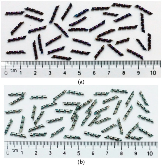
Figure 5.
Chip morphology in conventional machining (a) and thermal-assisted machining (b) which were conducted using an MC500 milling machine.
4.2. Experimental Machining at Room Temperature
In this study, each experiment was performed three times. Cutting force values, the average cutting force and the S/N ratios are shown in Table 6. The S/N ratios were calculated based on Equation (1). Synthetic analysis of the influence of the technological parameters on the cutting force in conventional machining is shown in Table 8. The S/N ratio of each factor with three levels is shown in Figure 5.
Table 8.
Multiple S/N response.
Analysis of the mean of multiple S/N ratios of control parameters for each level is shown in Table 7. From this, the optimum values in conventional machining of SKD11 were obtained as A3B1C1 with a cutting speed of 280 m/min, feed rate of 230 mm/min, and cutting depth of 0.5 mm, as shown in Figure 6.
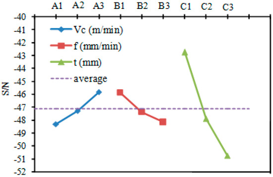
Figure 6.
S/N ratios of control parameters at room temperature.
The mathematical model of cutting force depends on technological parameters (Vc, f, t) in the milling of SKD11 steel at room temperature, and is described by Equation (2).
where FR is the synthetic cutting force, which is broken down into three component cutting forces, FXR, FYR, and FZR, with Equation (3):
a1, b1, c1, and d1 are the coefficients determined from the experiment. Using the nonlinear regression tool of Minitab 17 software, the nonlinear regression function in the milling of SKD11 steel at room temperature was found as Equation (4).
4.3. Experimental Machining at Elevated Temperatures
To study the influence of the thermal-assisted process on cutting force in the milling of SKD11 steel, experimental studies were conducted with L9 orthogonal array. Each experiment was performed three times for the average cutting force and the S/N ratio of each experiment, as shown in Table 7. The S/N ratio was calculated according to the Equation (1).
From the analysis of the S/N ratio for each control parameter at three levels, optimum controls were chosen for the minimum cutting force gain, which were A3B1C1D3 (Table 9 and Figure 7). The optimum cutting parameters and temperatures were obtained as a cutting speed of 280 m/min, feed rate of 230 mm/min, cutting depth of 0.5 mm and temperature of 400 °C.
Table 9.
Multiple S/N response.
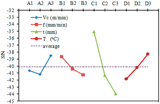
Figure 7.
S/N ratios of control parameters at elevated temperatures.
The cutting force doesn’t only affect the technological system such as machine, tool, and fixture, but also causes vibration in the cutting process, affecting the precision of the machining process. The goal of thermal-assisted machining is to reduce the cutting force to improve product quality. As the conclusions from previous studies, the elevated temperatures of the workpiece lead to reduce the hardness and strength of the machining material during heating time [1,2]. The material is softer, making the cutting process easier [3]. Therefore, the cutting force is reduced and the separating of the chips from the workpiece is easier. Figure 8 is a graph of conventional and elevated machining at 200 °C with cutting parameters at Vc = 190 m/min, f = 230 mm/min, t = 0.5 mm. Table 10 gives a comparison of the cutting force in conventional and elevated machining. Cutting force reduction ΔF (%) is according to Equation (5):
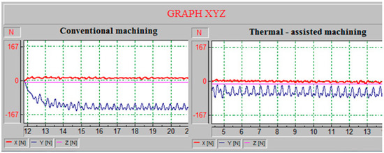
Figure 8.
Cutting force with cutting parameters at Vc = 190 m/min, f = 230 mm/min, t = 0.5 mm in conventional and thermal-assisted machining.
Table 10.
Comparison of cutting force in conventional and thermal-assisted machining.
The results show that the cutting force is strongly supported in thermal-assisted machining. The highest cutting force reduction was 66.9% in the eighth experiment with a temperature of 400 °C. The lowest cutting force reduction was 37.5% in the fifth experiment with a temperature of 200 °C. With the effect of high temperatures, the softening of the workpiece material reduces the friction between chips and the front of the tool, and between the back of the tool and the workpiece surface that is being machined. So, the cutting process is made easier.
4.4. Establishing Cutting Force Model with Thermal-Assisted Machining
a. Average Ratio Method
This method is based on the average ratio of the experimental results of the cutting force in conventional and thermal-assisted machining, as shown in Table 10.
The rate of cutting force during machining at elevated temperatures compared to conventional machining is a function of workpiece temperature at cutting time. The mathematical equation of the cutting force as Equation (6).
where f(T) is a function of the workpiece temperature at cutting time.
Based on results of the cutting force of these two machining methods with the same cutting parameters as in Table 10, the average ratio of the cutting forces reduction at different temperatures of 200 °C, 300 °C, and 400 °C was determined as shown in Table 11. Using Excel software, the equation f(T) was defined as in Equation (7). The results show that the equation f(T) is a linear equation. The graph of f(T) is shown in Figure 9, with the R-square variance analysis of 0.998 showing high reliability.
Table 11.
Average ratio of cutting force reduction.
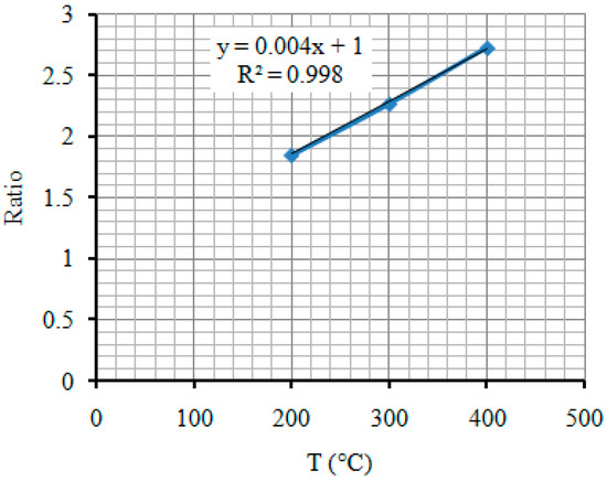
Figure 9.
Equation and graph of f(T).
So, the cutting force model in thermal-assisted machining is as seen in Equation (8).
Substituting Equation (4) into Equation (8), the cutting force model for thermal-assisted machining depends on the cutting parameters Vc, f, t and T and is written as Equation (9)
The cutting force in Equation (9) (FT(Eq.)) is compared with the experimental data (FT(Ex.)), as shown in Table 12. The error percentage (ΔFT (%)) is determined with Equation (10).
Table 12.
Estimation of error of cutting force determined with average ratio method.
The results show that the percentage of errors in some experiments is relatively large. The maximum error percentage is 27.4% in experiment 1. The next is 21% in experiment 8. So, it is necessary to propose another method to establish a cutting force model for machining at elevated temperature. The second method is presented in the next section.
b. Gauss-Newton Method
This study is based on the data set of L9 experimental parameters and the results of cutting force are defined as Table 8. The Gauss–Newton method was used to find nonlinear regression function (FT). This method was applied with the nonlinear regression tool of Minitab 17 software.
The cutting force model for thermal-assisted machining depends on the control parameters Vc, f, t, and T, as Equation (11).
where a2, b2, c2, d2, e2 are the coefficients determined from the experiment.
With nine-point experimental data in machining at elevated temperatures, the nonlinear regression function in thermal-assisted milling of SKD11 steel was defined as in Equation (12). The error percentage of the comparison with the experimental data was evaluated according to Equation (10). The results are shown in Table 13.
Table 13.
Estimation of error of cutting force determined with Gauss-Newton method.
The results in Table 14 show that the percentage of errors is relatively large. The highest error percentage is 23.6% in experiment 1. The error percentage is 18.7% in experiment 6. However, the error percentage of the Gauss–Newton method is lower than in the average ratio method.
Table 14.
S/N ratio of each experiment with various methods.
Therefore, this study proposes a new method to determine the cutting force equation in thermal-assisted machining of SKD11 steel, which is presented in the next section.
c. New determine the Cutting Force Equation in Thermal-Assisted Machining
Experiments at elevated temperatures used the orthogonal array Taguchi L9, as shown in Table 8, with four control parameters, which were Vc, f, t, and T, and three levels. The goal of minimizing the number of experiments was met; evaluation of the order of influence of control parameters, and optimization of output parameters was also a great success. However, finding the regression function with nine points was difficult due to the low number of regression points, while the number of control parameters was higher. The two methods of finding the cutting force regression described above gave very little accuracy. For these reasons, the study proposes a new equation (Equation (13)). This equation uses input data, which are the cutting force model for conventional machining at room temperature as in Equation (4), and elevated temperatures that support the machining process (Table 8). Then, the cutting force model for machining at elevated temperatures could be presented as a function of corresponding one at room temperature with the same cutting parameters and workpiece temperatures, as Equation (13):
where a3, b3, and c3 are the coefficients determined from experiments.
To find the regression function Equation (13), the results of the cutting force in conventional machining , which are determined from Equation (4) for nine corresponding cases from Table 6, and workpiece temperatures (T) (Table 8) were used as input data of Equation (13). While, the cutting force results in machining at elevated temperatures (Table 10) for nine corresponding cases were set as output data of Equation (13). By programming with MATLAB software (R2015a, The MathWorks Inc., Natick, MA, USA) using least squares, the coefficients a3, b3, and c3 were found, corresponding to 5.8027, 1.1336, and −0.5823, respectively. Equation (13) is rewritten as follows:
Substitute Equation (4) into Equation (14). Then, the cutting force model for thermal-assisted machining depends on the cutting parameters and the elevated temperatures that support machining, as shown in Equation (15).
To evaluate the accuracy of the new method and compare it with the two old methods, the study used the method of evaluating the S/N ratio variance of each method. First, the S/N ratios of the cutting force value in each experiment were determined according to Equation (16) with the standard value (experimental value) as the best value [33]. The results are presented in Table 14. Then, the variances of the test set at different temperature levels (200 °C, 300 °C, and 400 °C) were calculated according by Equation (17). The average S/N ratio for heating temperatures is shown in Table 15. The total variance of each method is found in Equation (18). From that, the accuracy of the three methods was evaluated. Table of variance results are shown in Table 16.
Table 15.
Average S/N ratio for heating temperatures.
Table 16.
Analysis of the variance of the cutting force determined by method.
MSD is the average square deviation defined as follows:
where yo is standard value; yi is the cutting force value determined from the model; and r is the number of tests in each experiment.
where mj1, mj2, and mj3 are average values of S/N ratios of the experiments at 200 °C, 300 °C, and 400 °C of the methods.
m is the average value of S/N ratios of nine experiments with each method and is defined as follows:
Table 16 shows that the new proposed method, which finds the cutting force regression through the cutting force model for conventional machining, has the least variance. This means that the results of the cutting force determined by the third method are the most accurate. Figure 10 is a graph of predicted cutting forces with the new method, and is compared with the experiment value.
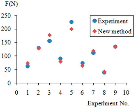
Figure 10.
Results of predicted cutting force with new proposal method and in comparison with the experiment.
Based on Equation (15), graphs showing the relationship between the cutting force and cutting parameters at different temperatures were made using the Maple software tool (Maplesoft, a division of Waterloo Maple Inc., Waterloo, ON, Canada) and are shown in Figure 11.
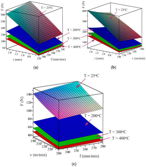
Figure 11.
The relationship between F with Vc, f and t at different temperatures (a) with fixed cutting speed, (b) with fixed feed rate, (c) with fixed cutting depth.
Figure 11 shows that, as temperature increases, the cutting force decreases. However, the cutting force decreases gradually as the billet temperature increases in order from room temperature to 200 °C, 300 °C, and 400 °C. Figure 11a,b are the cutting force graph when fixing Vc and f shows the maximum slope of the cutting force graph when changing the cutting depth. Thus, t has the greatest influence on the cutting force. Figure 11c is the cutting force graph when fixing t. The slope in changing Vc is greater than the one in changing f. That means the effect of Vc is greater than the one of the feed rate (f).
5. Conclusions
This paper studied the chip formation and the cutting forces during thermal-assisted machining for SKD11. The following specific conclusions were drawn on the work:
- Thermal-assisted process effect on chip morphology. The chip’s colour change in TAM with brighter colour while chip’s colour is violet-black in conventional machining.
- It is observed that the maximum cutting forces reduction of 66.9% in TAM when compared to conventional machining.
- The optimal condition of parameters obtained for thermal-assisted machining are cutting speed of 280 m/min, feed rate of 230 mm/min, cutting depth of 0.5 mm, and temperature of 400 °C.
- A new method for predicting the cutting forces in thermal-assisted milling by induction heating of SKD11 is presented show good result when comparing with experimental data.
Author Contributions
M.T.-B. and N.D.-T. designed most of the experiments, performed most experiments, analyzed the results and wrote this manuscript. B.T.-L. and D.V.-C. helped gave some constructive suggestions about how to write this manuscript.
Funding
This research is funded by the Vietnam National Foundation for Science and Technology Development (NAFOSTED) under grant number “107.02-2016.01”.
Conflicts of Interest
The authors declare no conflict of interest.
References
- Shatarupa, G.; Gurav, P.; Rajiv, B.; Suvrna, P. A Review on Effect of Cutting Parameters in Hot Turning Operation on Surface Finish. Int. J. Eng. Dev. Res. 2016, 4, 55–61. [Google Scholar]
- Baili, M.; Wagner, V.; Dessein, G.; Sallaberry, J.; Lallement, D. An experimental investigation of hot machining with induction to improve Ti-5553 machinability. Appl. Mech. Mater. 2011, 62, 67–76. [Google Scholar] [CrossRef]
- Brecher, C.; Emonts, M.; Rosen, C.; Hermani, J. Laser-assisted Milling of Advanced Materials. Phys. Procedia 2011, 12, 599–606. [Google Scholar] [CrossRef]
- Germain, G.; Santo, P.D.; Lebrun, J.L. Comprehension of chip formation in laser assisted machining. Int. J. Mach. Tools Manuf. 2011, 51, 230–238. [Google Scholar] [CrossRef]
- Amin, K.M.N.; Binti, S.; Binti, M.; Lajis, M.A. Effects of workpiece preheating on surface roughness, chatter and tool performance during end milling of hardened steel D2. J. Mater. Process. Technol. 2007, 1, 466–470. [Google Scholar] [CrossRef]
- Thi-Hoa, P.; Thi-Bich, M.; Van-Canh, T.; Tien-Long, B.; Duc-Toan, N. A study on the cutting force and chip shrinkage coefficient in high-speed milling of A6061 aluminum alloy. Int. J. Adv. Manuf. Technol. 2018, 98, 177–188. [Google Scholar] [CrossRef]
- Ozler, L.; Inan, A.; Ozel, C. Theoretical and experimental determination of tool life in hot machining of austenitic manganese steel. Int. J. Mach. Tools Manuf. 2001, 41, 163–172. [Google Scholar] [CrossRef]
- Amin, K.M.N.; Ginta, T.L. Heat-Assisted Machining; Elsevier: Amsterdam, The Netherlands, 2014; Volume 11. [Google Scholar]
- Sadeghipour, K.; Dopkin, J.A.; Li, K. A computer aided finite element/experimental analysis of induction heating process of steel. Comput. Ind. 1996, 28, 195–205. [Google Scholar] [CrossRef]
- Pham, T.-H.; Mac, T.-B.; Tong, V.-C.; Banh, T.-L.; Nguyen, D.-T. Simulation and experimental studies to verify the effect of cutting parameters on chip shrinkage coefficient and cutting forces in machining of A6061 aluminum alloy. Adv. Mech. Eng. 2016, 8. [Google Scholar] [CrossRef]
- Ginta, T.L.; Amin, A.K.M.N. Thermally-assisted end milling of titanium alloy Ti-6Al-4V using induction heating. Int. J. Mach. Mach. Mater. 2013, 14, 194–212. [Google Scholar] [CrossRef]
- Sun, S.; Brandt, M.; Dargusch, M.S. The Effect of a Laser Beam on Chip Formation during Machining of Ti6Al4V Alloy. Phys. Metall. Mater. Sci. 2010, 41, 1573–1581. [Google Scholar] [CrossRef]
- Wang, Z.Y.; Rajurkar, K.P.; Fan, J.; Lei, S.; Shin, Y.C.; Petrescu, G. Hybrid machining of Inconel 718. Int. J. Mach. Tools Manuf. 2003, 43, 1391–1396. [Google Scholar] [CrossRef]
- Novak, J.W.; Shin, Y.C.; Incropera, F.P. Assessment of plasma enhanced machining for improved machinability of Inconel 718. J. Manuf. Sci. Eng. 1997, 119, 125–129. [Google Scholar] [CrossRef]
- Leshock, C.E.; Kim, J.-N.; Shin, Y.C. Plasma enhanced machining of Inconel 718: Modeling of workpiece temperature with plasma heating and experimental results. Int. J. Mach. Tools Manuf. 2001, 41, 877–897. [Google Scholar] [CrossRef]
- Shi, B.; Attia, H.; Vargas, R.; Tavakoli, S. Numerical and experimental investigation of laser-assisted machining of Inconel 718. Mach. Sci. Technol. 2008, 12, 498–513. [Google Scholar] [CrossRef]
- Dumitrescu, P.; Koshy, P.; Stenekes, J.; Elbestawi, M.A. High-power diode laser assisted hard turning AISI D2 tool steel. Int. J. Mach. Tools Manuf. 2006, 46, 2009–2016. [Google Scholar] [CrossRef]
- Rajagopal, S.; Plankenhorn, D.J.; Hill, V.L. Machining aerospace alloys with the aid of a 15 kW laser. J. Appl. Metalwork. 1982, 2, 170–184. [Google Scholar] [CrossRef]
- Ganta, V.; Chakradhar, D. Multi objective optimization of hot machining of 15-5PH stainless steel using grey relation analysis. Procedia Mater. Sci. 2014, 5, 1810–1818. [Google Scholar] [CrossRef]
- Muhammad, R.; Maurotto, A.; Demiral, M.; Roy, A.; Silberschmidt, V.V. Themelly enhanced ultrasonically assisted machining of Ti alloy. CIRP J. Manuf. Sci. Technol. 2014, 7, 159–167. [Google Scholar] [CrossRef]
- Amin, A.K.M.N. The effect of preheating of work material on chatter during end milling of medium carbon steel performed on a vertical machining center (VMC). J. Manuf. Sci. Eng. 2003, 125, 674–680. [Google Scholar] [CrossRef]
- Lajis, M.A.; Amin, A.K.M.N.; Karim, A.N.M.; Radzi, H.C.D.M.; Ginta, T.L. Hot machining of hardened steels with coated carbide inserts. Am. J. Eng. Appl. Sci. 2009, 2, 421–427. [Google Scholar] [CrossRef]
- Amin, A.K.M.N.; Talantov, N.V. Influence of the Instability of Chip Formation and Preheating of Work on Tool Life in Machining High Temperature Resistant Steel and Titanium Alloys. Mech. Eng. Res. Bull. 1986, 9, 52–62. [Google Scholar]
- Amin, A.K.M.N.; Saad, M.H.B.; Arif, M.D. Modeling & Optimization of Surface Roughness & Vibration Amplitude in Heat Assisted End Milling of SKD 11 Tool Steel using Ball Nose Tool. Adv. Mater. Res. 2012, 541, 799–803. [Google Scholar]
- Xavierarockiaraj, S.; Kuppan, P. Investigation of cutting forces, surface roughness and tool wear during Laser assisted machining of SKD11Tool steel. Procedia Eng. 2014, 97, 1657–1666. [Google Scholar] [CrossRef]
- Edwin, K.P.C.; Stanislaw, H.Z. An Introduction to Optimization, 2nd ed.; John Wiley & Sons: Hoboken, NJ, USA, 2001. [Google Scholar]
- Montgomery, D.C. Design, Analyses of Experiments, 3rd ed.; John Wiley & Sons: Hoboken, NJ, USA, 1997. [Google Scholar]
- Giasin, K.; Ayvar-Soberanis, S.; Hodzic, A. Evaluation of crygenic cooling and minimum quatity lubrication effects on machining GLARE laminates using design of experiments. J. Clean. Prod. 2016, 135, 533–548. [Google Scholar] [CrossRef]
- Giasin, K.; Ayvar-Soberanis, S. An investigation of burrs, chip formation, hole size, circularity and delamination during drilling operation of GLARE using ANOVA. J. Compos. Struct. 2017, 159, 745–760. [Google Scholar] [CrossRef]
- Nguyen, D.-T.; Kim, Y.-S. Combination of isotropic and kinematic hardening to predict fracture and improve press formability of a door hinge. Proc. Inst. Mech. Eng. Part B J. Eng. Manuf. 2009, 224, 435–445. [Google Scholar] [CrossRef]
- Duc-Toan, N.; Young-Suk, K.; Dong-Won, J. Coupled thermomechanical finite element analysis to improve press formability for camera shape using AZ31B magnesium alloy sheet. Met. Mater. Int. 2012, 18, 583–595. [Google Scholar] [CrossRef]
- Du, S.; Chen, M.; Xie, L.; Zhu, Z.; Wang, X. Optimization of process parameters in the high-speed milling of titanium alloy TB17 for surface integrity by the Taguchi-Grey relational analysis method. Adv. Mech. Eng. 2016, 8, 1–12. [Google Scholar] [CrossRef]
- Taguchi, G. On-Line Quality Control during Production; Japan Standard Association: Tokyo, Japan, 1981. [Google Scholar]
- Wang, C.; Xie, Y.; Zheng, L.; Qin, Z.; Tang, D.; Song, Y. Research on the Chip Formation Mechanism during the high-speed milling of hardened steel. Int. J. Mach. Tools Manuf. 2014, 79, 31–48. [Google Scholar] [CrossRef]
- Wang, C.; Ding, F.; Tang, D.; Zheng, L.; Li, S.; Xie, Y. Modeling and simulation of the high-speed milling of hardened steel SKD11 (62 HRC) based on SHPB technology. Int. J. Mach. Tools Manuf. 2016, 108, 13–26. [Google Scholar] [CrossRef]


© 2018 by the authors. Licensee MDPI, Basel, Switzerland. This article is an open access article distributed under the terms and conditions of the Creative Commons Attribution (CC BY) license (http://creativecommons.org/licenses/by/4.0/).