Article

Analysis of Failure-Mode Dependent Joint Strength in Hole Clinching from the Aspects of Geometrical Interlocking Parameters

1
Dongnam Regional Division, Korea Institute of Industrial Technology, Gyeongsangnam-do 52845, Korea
2
Green Transportation System of Industrial Liaison Innovation Center, Pusan National University, 63, Busandaehak-ro, Geumjeong-gu, Pusan 609-735, Korea
3
School of Mechanical Engineering, Pusan National University, Busan 46241, Korea
4
Department of Industrial and Information Engineering and Economics, University of L’Aquila, 67100 L’Aquila AQ, Italy
5
Graduate School of Convergence Science, Pusan National University, Busan 46241, Korea
*
Author to whom correspondence should be addressed.
Metals 2018, 8(12), 1020; https://doi.org/10.3390/met8121020
Submission received: 1 October 2018 / Revised: 26 October 2018 / Accepted: 1 December 2018 / Published: 4 December 2018

Abstract

:
The hole-clinching process is one of the mechanical methods for joining dissimilar materials, such as aluminum alloy with advanced high-strength steel, hot-pressed steel, and carbon fiber reinforced plastics, employing forming technology-based methods. In joint design, the analysis of the failure-mode dependent joint strength is a crucial step in achieving structural performance for practical applications. In this study, the influence of the geometrical interlocking parameters on the failure-mode dependent joint strength was investigated in order to design the geometrical interlocking shape of the hole-clinched joint to achieve a target joint strength. Moreover, the failure process of the hole-clinched joint under pullout loading condition was studied to determine the geometrical interlocking parameters that affect joint strength. Based on the results of the finite element analysis, an analytical approach for the failure-mode dependent joint strength was proposed to predict the strength of the hole-clinched joint. In addition, the proposed analytical approach was applied to the hole-clinching process with dissimilar materials. Its effectiveness was then verified using the cross-tension test. Accordingly, it was found that it was possible to predict the failure modes and joint strength with a maximum error of 7.8%.

Graphical Abstract

1. Introduction

Currently, the multi-material design concept is widely used in practical applications. Specifically, structures designed with multi-materials utilize light-weight components, such as advanced high-strength steel, aluminum alloy, and carbon fiber reinforced plastic (CFRP), all of which are extensively used in automotive bodies [1,2,3]. The success of such multi-material designed structures greatly depends on the methods employed to join the body components made of dissimilar materials. In this regard, there are several methods suitable for joining lightweight materials, such as adhesive bonding, friction stir welding, mechanical fastening, self-piercing rivets, and mechanical clinching [4,5,6,7,8,9].
Mechanical joining using forming technology, such as self-piercing rivets and clinching, has emerged as a remarkable technique for joining dissimilar materials because of its low-cost and high-speed fastening [10,11]. Hole-clinching is also one of the new joining methods using forming technology to join dissimilar materials, that are difficult or may even be impossible to apply by the conventional mechanical joining methods [12,13,14]. In hole-clinching, the geometrical interlocking is formed through a pilot hole made on low-ductility materials, as shown in Figure 1. Furthermore, the load-bearing characteristics of a hole-clinched joint is dependent on the geometrical interlocking shape.
The analysis of the joint failure behavior is important to achieve the target structural performance of joints. In the design step of the joining process, several numerical simulations or experiments have been conducted to obtain the optimal joining tool shape and process conditions for maximizing the joint strength. However, it is difficult to predict joint strength only with geometrical interlocking shape from the results of the forming simulation for hole clinching process, which means additional simulations are required to assess joint strength. In view of such joint design procedures, the existence of an accurate analytical approach that can be employed for predicting the joint strength and its failure mode would greatly reduce the computational time for the joining process design. In relation to the foregoing, Coppieters et al. [15] have predicted the pull-out strength of clinched connections through analytical methods. Moreover, in order to predict the joint strength and its failure mode, Lee et al. [16] proposed a procedure for the design of conventional mechanical clinching tools to determine the appropriate values of the geometrical interlocking parameters. Additionally, He et al. [17] proposed a theoretical model for evaluating joint strength and experimentally verified its effectiveness as well.
The objective of this study is to analyze the failure-mode dependent joint strength in terms of the geometrical interlocking parameters, which influence the load-bearing characteristics of a hole-clinched joint. Accordingly, analytical expressions were derived from the geometrical interlocking parameters to predict the joint strength in resisting neck fracture and button separation. Further, the proposed analytical expressions were verified through the hole-clinching experiment and cross-tension test. Finally, the effects of the process parameters on the failure-mode dependent joint strength as well as how they were utilized in the design of the hole-clinching process were identified.

2. Failure Mode Dependent Joint Strength in Hole-Clinching

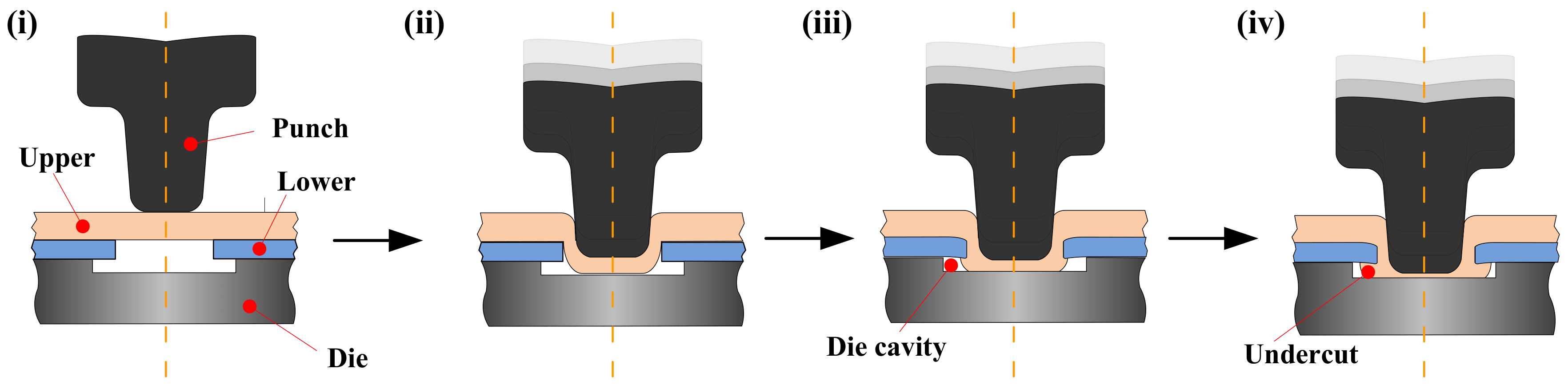
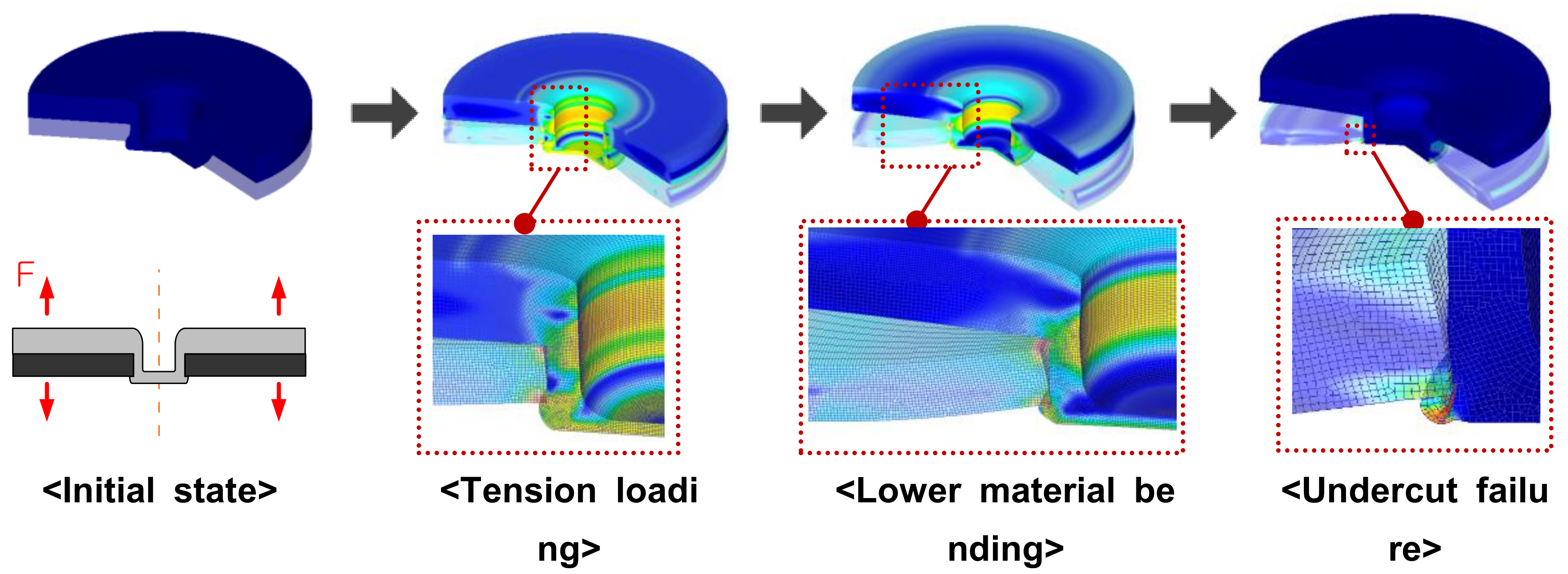
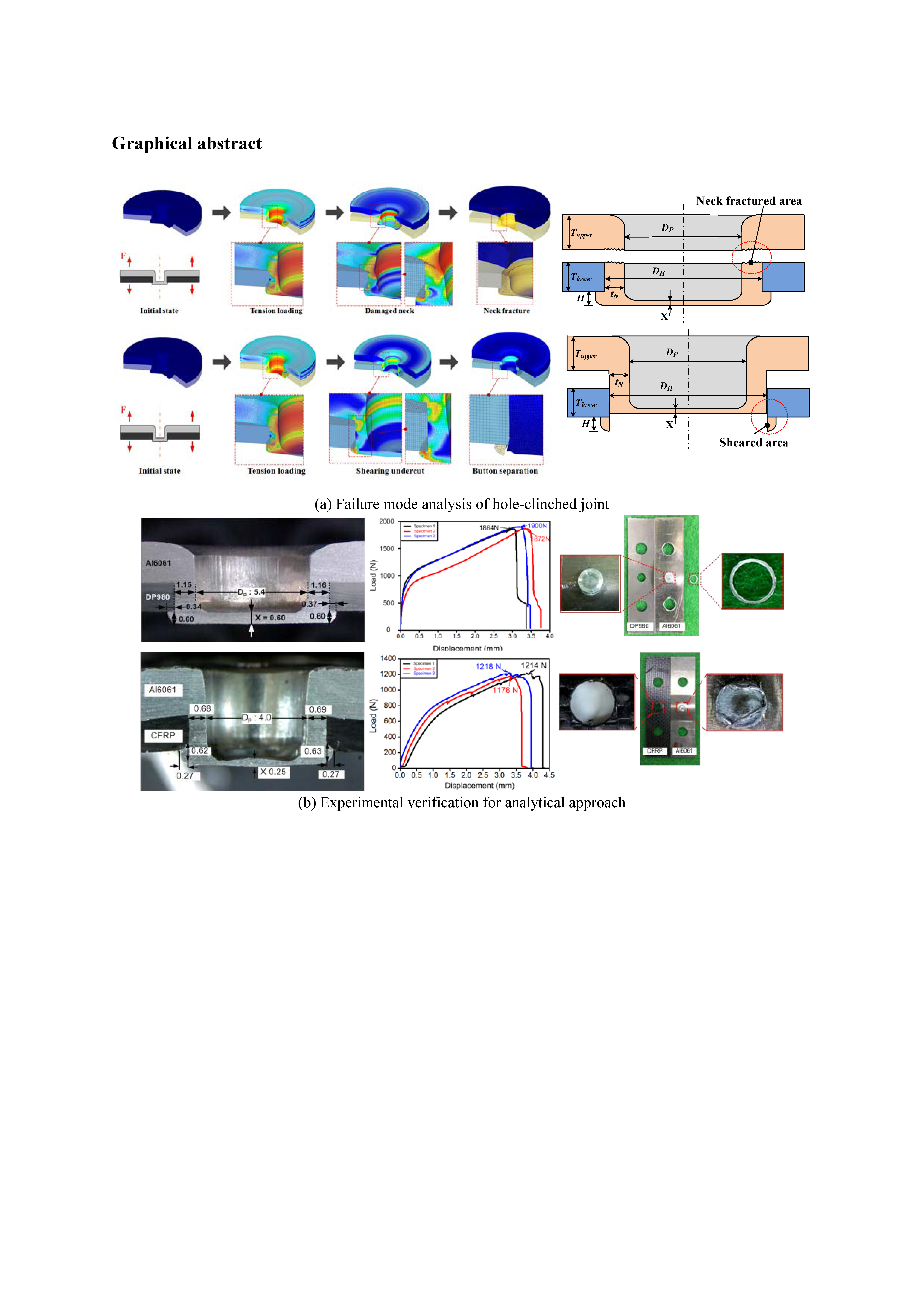
2.1. The Failure Mechanisms of Hole-Clinched Joints

In order to derive an analytical expression for the failure-mode dependent joint strength, it is necessary to understand the failure mechanisms of a hole-clinched joint. The failure mechanisms of hole-clinched joints under pull-out loading conditions were studied, as illustrated in Figure 2. The hole clinched joint studied in the previous study [18] was studied in FE-analysis. Upper and lower materials were Al6061 and DP980, whose material properties are listed in Table 1. The friction coefficient between the two materials was assumed to be 0.1. External load was applied to the upper material and the lower material was fixed to describe the pull-out loading condition. The failure behavior of upper material was considered by a normalized Cockloft and Latham’s equation supported in a commercial software, DEFORM (Version 10.0, Scientific Forming Technologies Corporation, Columbus, OH, USA) [19].
In the neck fracture mode (Figure 2a,c), the pull-out load is applied to the neck of the hole-clinched joint, concentrating the stress caused by the load on the neck of the upper material. Consequently, when the stress at the neck reaches failure stress of upper material, the neck is fractured. In the button separation mode (Figure 2b,d), the shear stress is developed at the undercut by the pull-out load. As the stress at the undercut reaches the shear yield stress, the hole-clinched joint is separated through the shear deformation of the undercut.

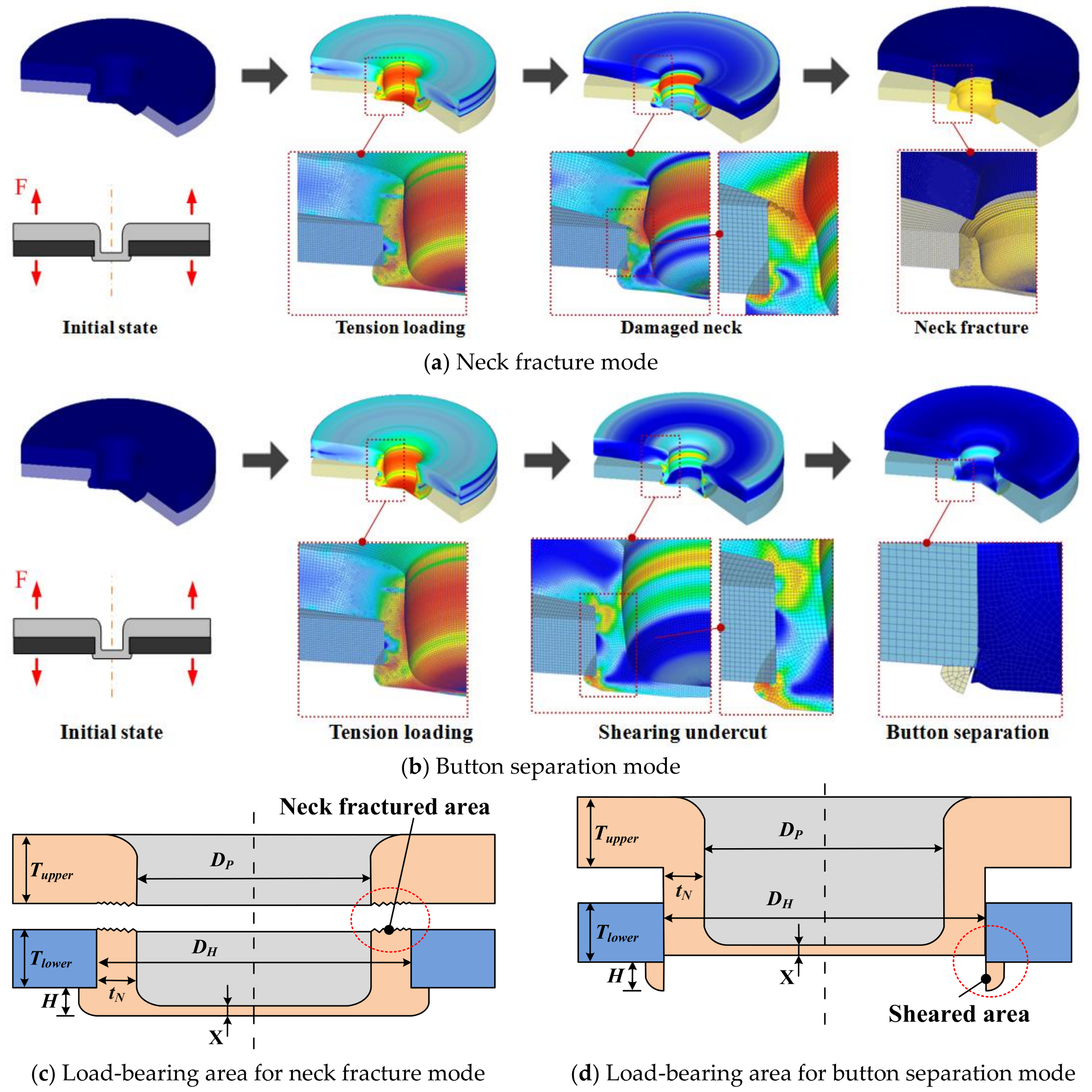
2.2. Joint Strength for Neck-Fracture and Button Separation Mode

According to a previous study [18], the neck-fracture and button separation load of the hole-clinched joint, FN and FB, can be expressed as follows:
F N = σ ¯ f A N = σ ¯ f π ( D p t N + t N 2 )
F B = τ ¯ f A B = τ ¯ f π ( D P + 2 t N ) H = τ ¯ f π D H H
The geometrical factors, such as punch diameter (DP), neck thickness (tN), pilot hole diameter (DH), and die depth (H), affect the load bearing areas of the hole-clinched joint for each failure mode. These factors can be determined by the geometrical relationship among the design parameters of the hole-clinching process. Thus, in order to predict the joint strength for neck facture and button separation, it is essential to define the failure stress of the upper materials at neck ( σ ¯ f ) and shear yield stress of undercut ( τ ¯ f ).
In this study, the failure stress at neck, σ ¯ f , in neck fracture mode has been simply assumed as the ultimate tensile strength of upper materials. And the shear yield stress at undercut, τ ¯ f , in button separation mode has been assumed as equivalent stress determined by the stress–strain curve equation following Equation (3):
τ ¯ f = K ε U n 3
In the hole clinching process, the bottom of upper material was compressed between punch and die and spread to make undercut. The true strain at the undercut, ε U can be assumed as following Equation (4):
ε U = ln ( X T upper )
where, X is the bottom thickness of upper material.

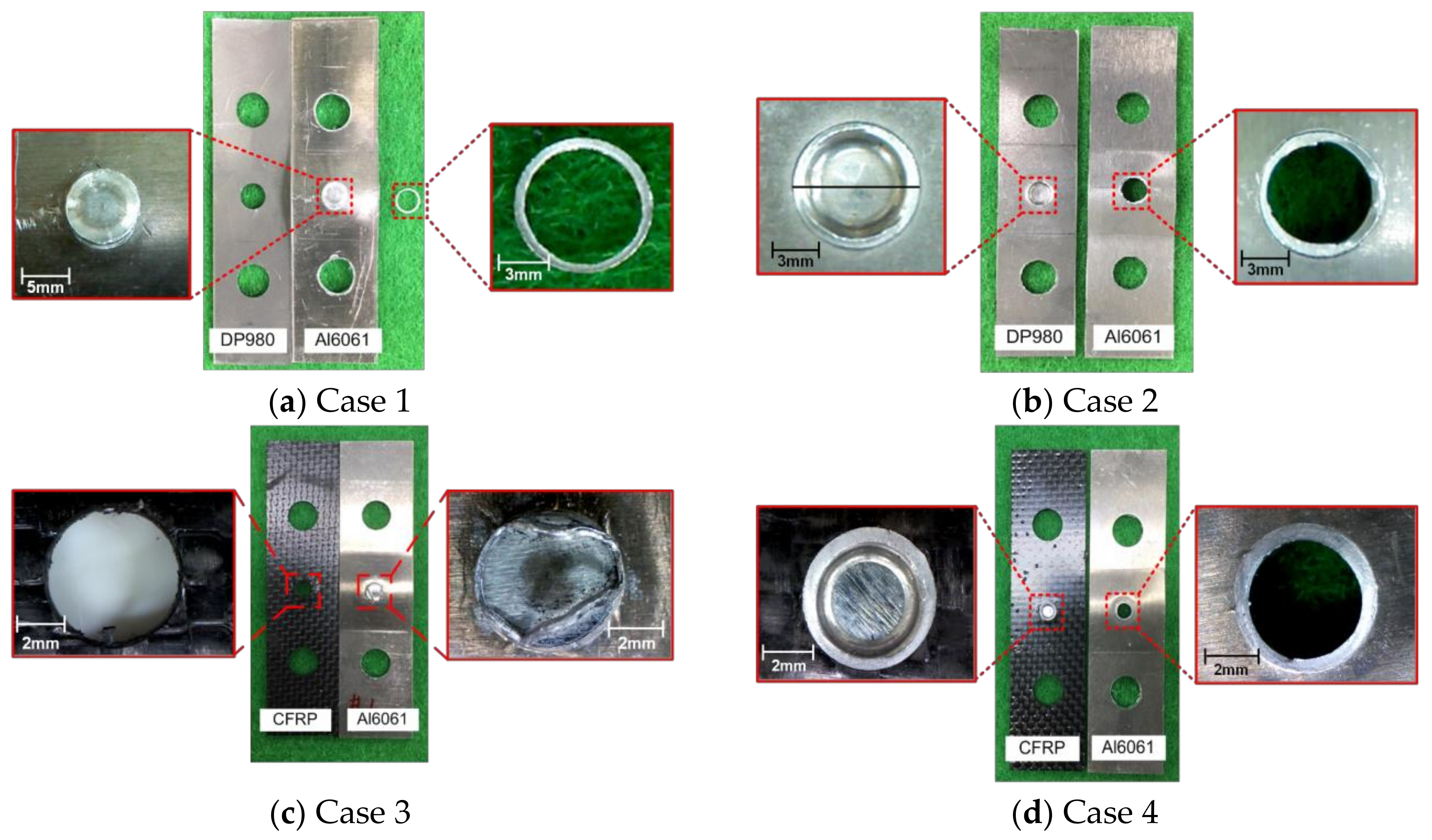
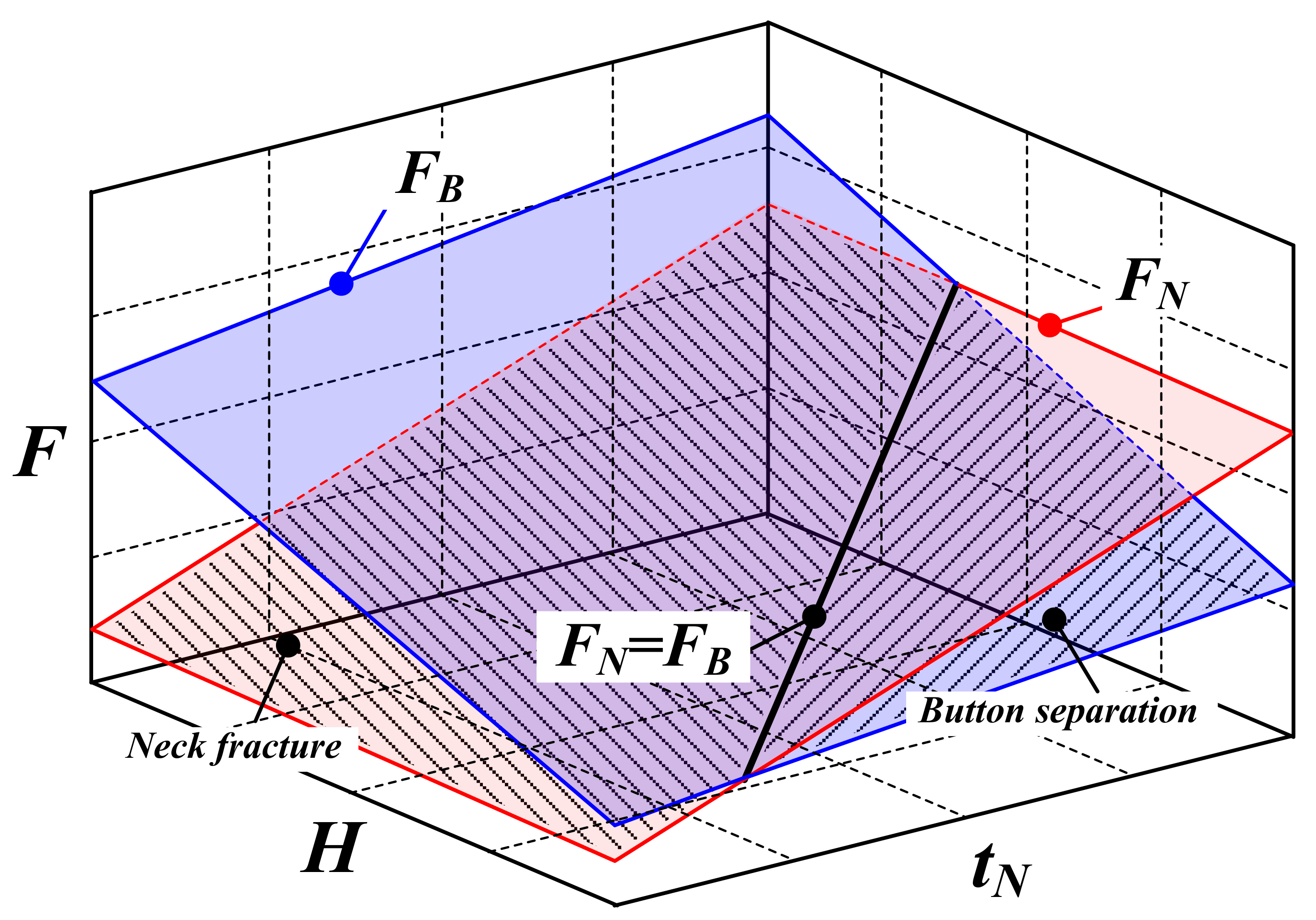
2.3. Identification of Failure Mode

For the specified geometrical interlocking shape of the hole-clinched joint, the joint strength for each failure mode predicted by Equations (1) and (2) indicated the pull-out load-bearing capacity of the neck and undercut of the upper materials. Accordingly, the failure mode of the hole-clinched joint could be determined on the basis of the smaller joint strength between the two fracture modes—the neck fracture and button separation. Therefore, the failure-mode dependent joint strength of the hole-clinched joint, F, can be expressed as Equation (5) below:
F = min ( F N , F B )

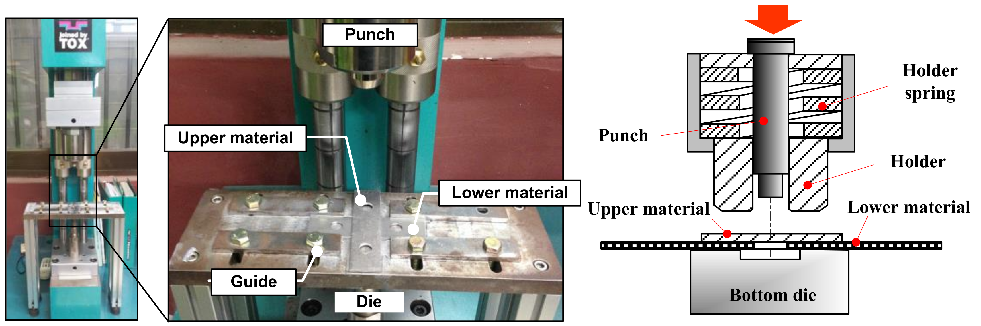
3. Experimental Verification of the Failure-Mode Dependent Joint Strength

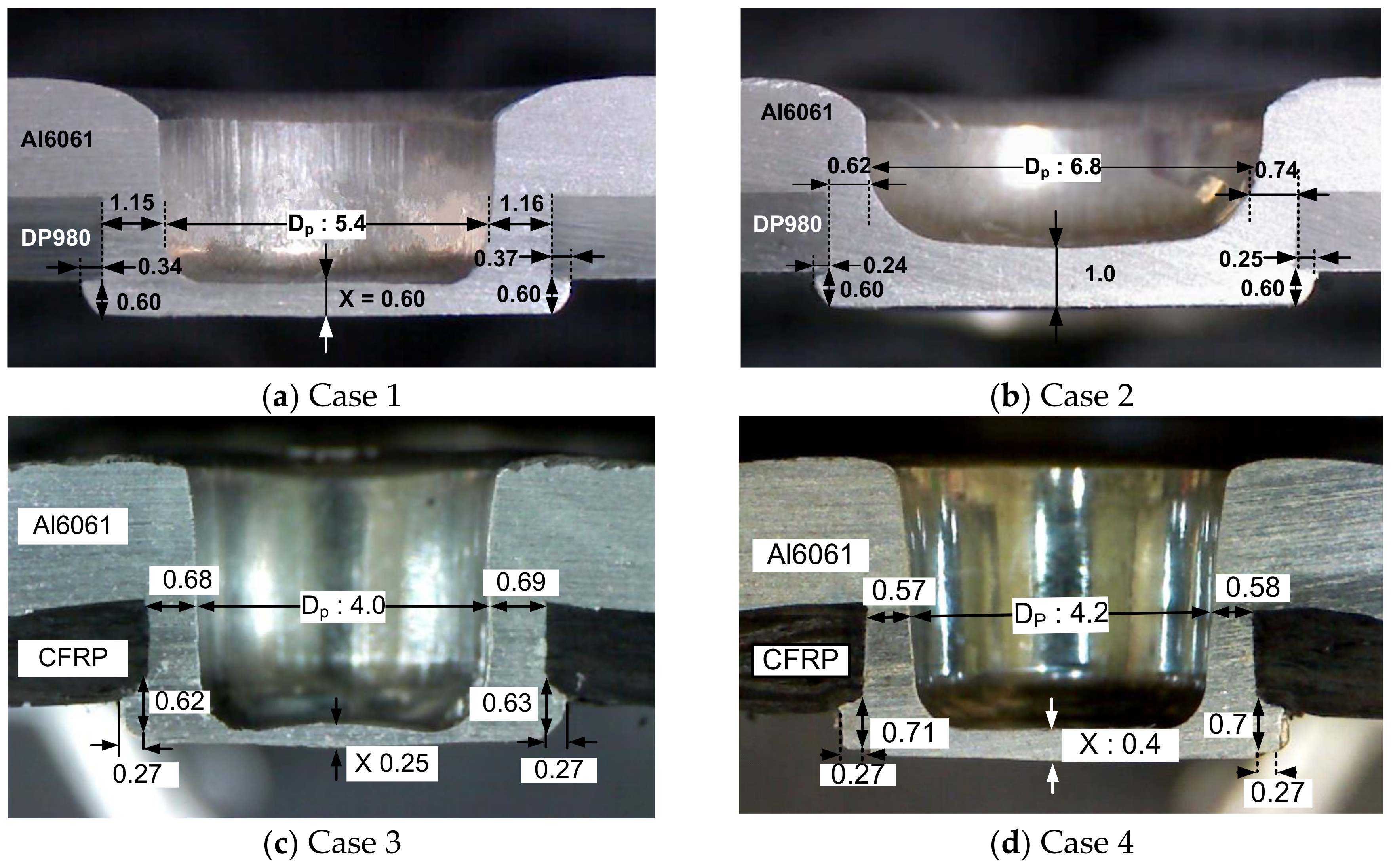
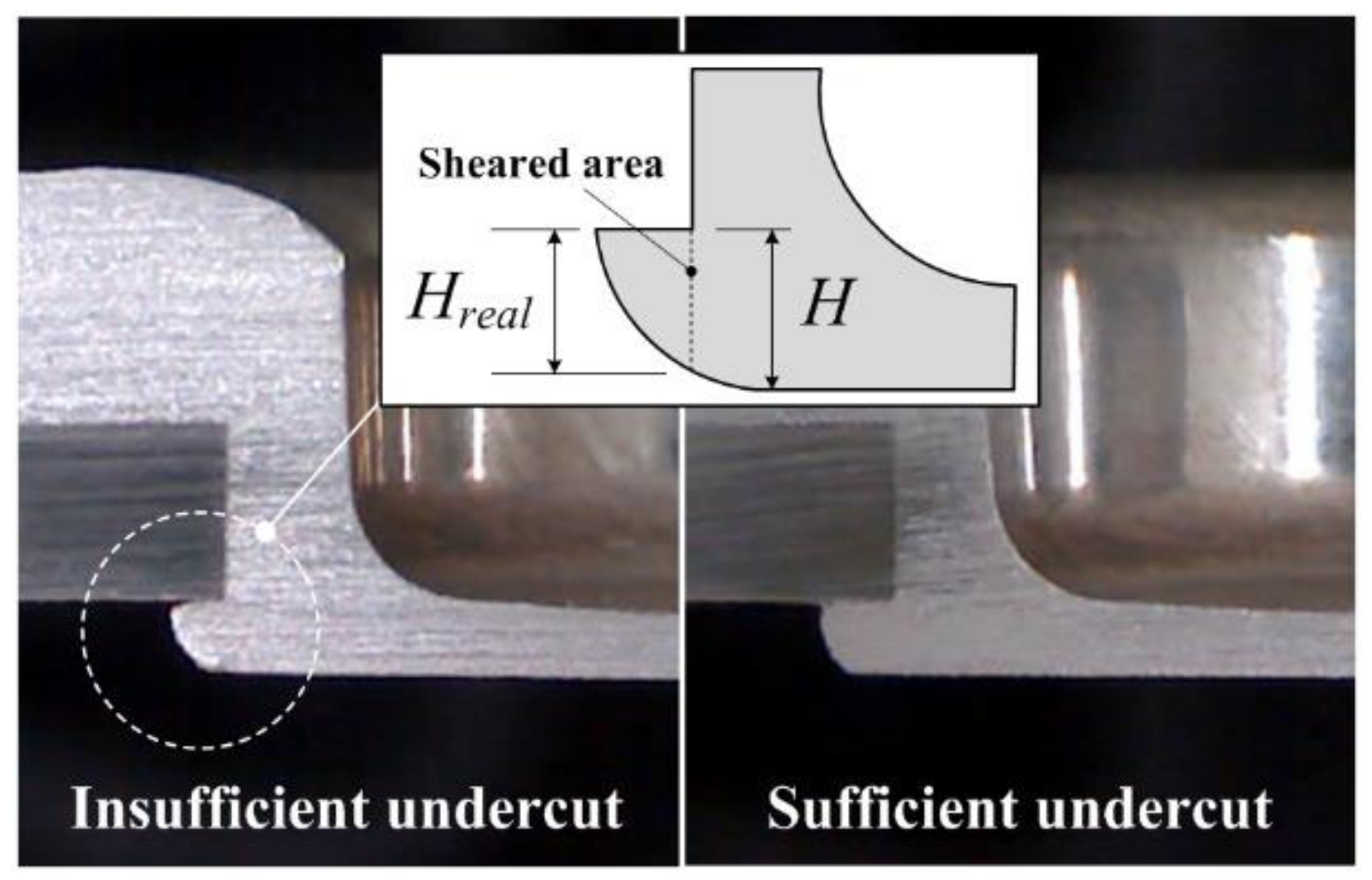
3.1. Geometrical Interlocking Parameter

The hole-clinching experiments were conducted on joining of Al6061 with CFRP to verify the effectiveness of the aforementioned analytical approach. Hole clinched joints with A6061-DP980, which were described in previous study [18], were also included in experimental cases. After the experiment, the cross-section of the hole-clinched joint was observed to evaluate its geometrical interlocking parameters. A press machine with a 10-kN load capacity and the tools used in the hole-clinching experiment are shown in Figure 3. The mechanical properties of materials are evaluated by tensile testing. The stress–strain curve equations of Al6061 and DP980 are expressed by the power law model. The hole-clinching process conditions are summarized in Table 2.
Through the hole-clinching experiment, the geometrical interlocking parameters of hole clinched joints were evaluated by optical observation as shown in Figure 4. The geometrical interlocking parameters were applied to Equations (1) and (2) to calculate the failure loads that caused neck fracture and button separation. The failure loads of the two failure modes were compared and the failure mode with the least failure load value is considered as the failure mode and intrinsic strength of the hole-clinched joint, respectively. It was predicted that button separation was the failure mode for Case 1 and Case 3, and that the joint strengths were estimated as 1939 and 1229 N, respectively. On the other hand, the joint strengths of Cases 2 and 4, whose failure modes were predicted as the neck fracture mode, were estimated as 1807 and 1085 N, respectively. The joint strengths and failure modes for all cases predicted by the proposed approach are summarized in Table 3.

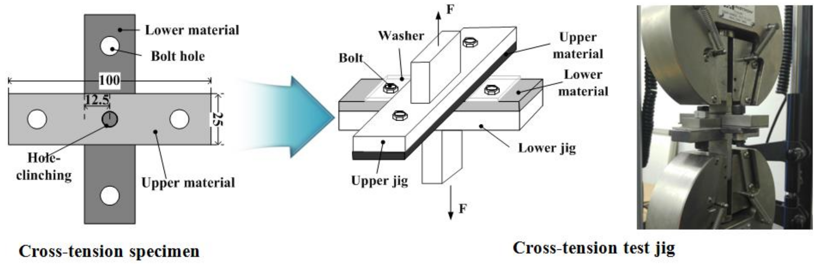
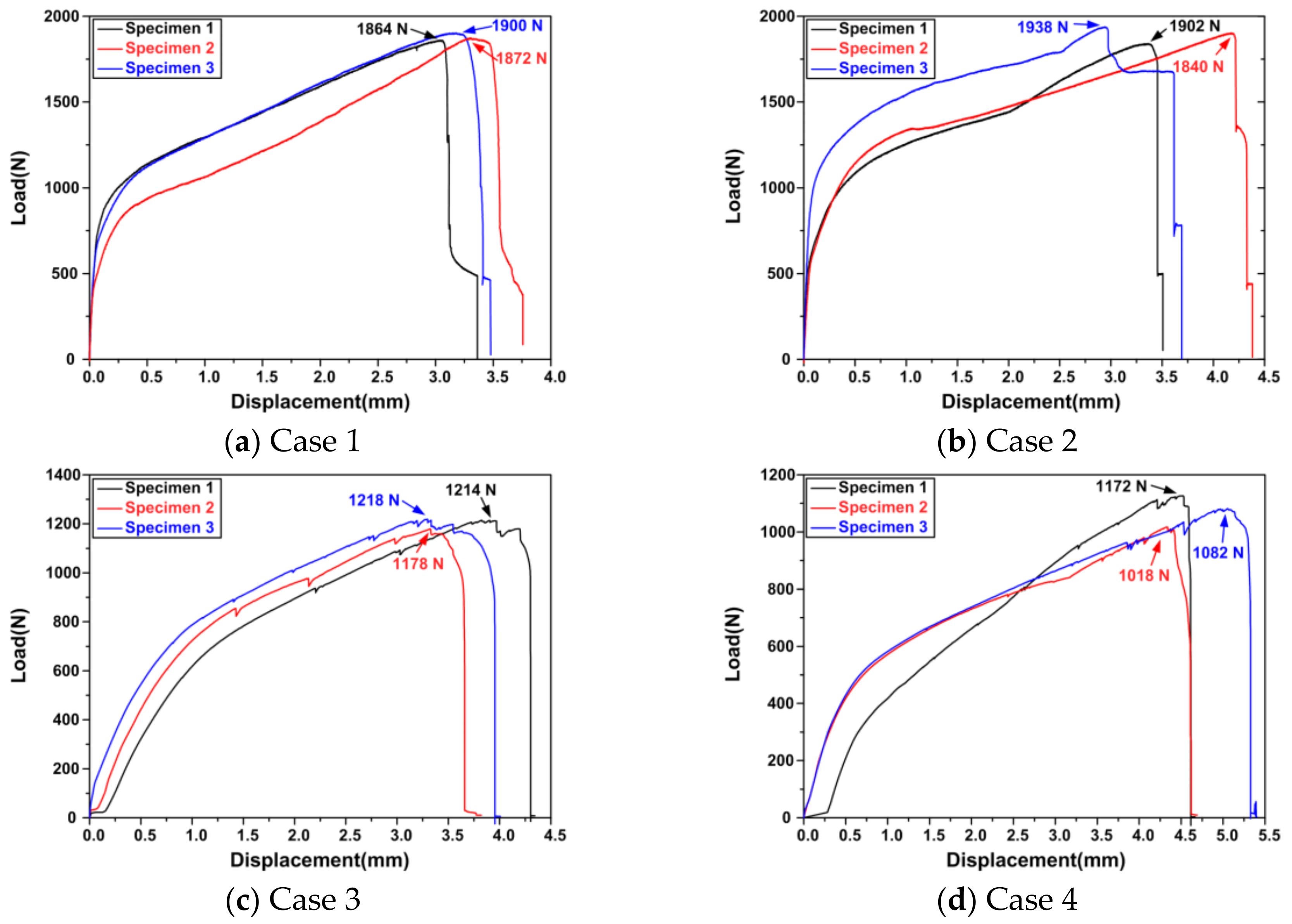
3.2. Evaluation of Joint Strength

The joint strengths and failure modes for all the experimental cases were evaluated to verify the effectiveness of the proposed analytical approach. The cross-tension test [20] was adopted to simulate the pull-out loading condition, as shown in Figure 5. The load–displacement curves obtained from the cross-tension test are shown in Figure 6. The average joint strength and failure mode of all experimental cases were compared with the values predicted by the analytical approach in Table 4. The joint strengths of Cases 1 and 3 with button separation were evaluated as 1880 ± 28 N and 1203 ± 49 N with errors of ‒3.0 ± 1.4% and 2.8 ± 4.0%, respectively. The joint strengths of Case 2 and Case 4 with neck fracture were 1885 ± 64 N and 1076 ± 45 N with errors of 4.3 ± 3.5% and 0.6 ± 4.1%, respectively.
The failure modes of the specimens are shown in Figure 7. In all cases, the same failure mode as predicted in the analytical approach was observed. In Cases 1 and 3, the undercut of the hole-clinched joint was fractured by shear stress, resulting in button separation. These results demonstrate that the joint strength for button separation indicates that the undercut fracture load was caused by shear stress. The undercut of the hole-clinched joint with CFRP and Al6061 was partially fractured, whereas that with DP980 and Al6061 was completely fractured. The joint strength variations of the hole-clinched joint with CFRP and Al6061 were relatively larger than those of the hole-clinched joint with DP980 and Al6061 because of the partial fracture of the undercut.
In Cases 2 and 4, the neck of upper material was fractured by tensile stress. The deviation of the neck thickness was observed at the neck facture area. This deviation induced an uneven amount of stress distributed in the neck when the pull-out load was applied to the hole-clinched joint. Because of the stress concentration on the relatively thin side, the neck thickness could induce fracture. Because the undercut was restrained between the die bottom surface and lower materials, the sheared area was constant and stress was equally distributed in the button separation mode. On the other hand, in the cross-tension test, the maximum load deviations were relatively greater in the neck fracture mode than that in button separation.

4. Discussions

4.1. Relationship between the Geometrical Interlocking Parameters and Joint Strength

The purpose of the analytical approach to prediction of failure mode dependent joint strength is to determine the geometrical interlocking parameters of hole clinched joints to obtain the desired joint strength. In this section, we discuss how the proposed analytical approach could be applied to design of the hole clinching process. Also, the factors influencing the failure mode dependent joint strength are discussed in terms of hole clinching process design.
The relationship between the geometrical interlocking parameters and failure-mode dependent joint strength is illustrated in Figure 8. For the given punch diameter, there are two surfaces that indicate the joint strengths of the neck fracture and button separation mode. The intersection line (FN = FB) shows the optimal strength of the hole-clinched joint, where the neck fracture and button separation mode strengths are in equilibrium. This relationship can provide a modification direction for the hole-clinching process design to improve joint strength. When the punch diameter is given, the neck thickness and undercut height, which are needed to obtain the target joint strength, are determined in the initial design step. However, the geometrical interlocking parameters obtained by the plastic deformation in the hole-clinching process are different from the initial design value. Occasionally, because of this, the target joint strength is not reached. Finally, in order to improve the joint strength, it is necessary to modify the design of the hole-clinching process in accordance with each failure mode.
If the hole-clinched joint has the neck fracture mode, the neck thickness must be increased in order to increase the joint strength. The increase in the neck thickness can be calculated using Equation (1). The diameters of the hole and die are redesigned to ensure that there is clearance at the section where the neck of the upper materials is formed. On the other hand, in the button separation mode, the undercut height must be increased in order to increase joint strength. The increase in the undercut height can be calculated using Equation (2).
According to Equation (2), the undercut length (tU) did not directly influence the undercut joint strength. In the hole-clinching process, the barreling effect forms the undercut as the material indented into the die cavity is spread by the punch. If the undercut is insufficient, the actual undercut height is smaller than the designed value, as shown in Figure 9. As a result, when button separation occurs, the actual joint strength may be less than the expected value. Thus, a certain length is required in order to make a geometrical interlocking shape with sufficient joint strength.

4.2. Lower Material

The parameters related to the lower material were not considered in the analytical approach to predict joint strength and failure mode. As shown in the experimental results, even when the lower material is changed from DP980 to CFRP, it has no significant effect on the prediction of joint strength and fracture mode. However, the change in hole diameter due to the bending of the CFRP laminate shows the possibility of a new failure mode in which button separation occurs without shear of the undercut.
Figure 10 shows the failure process of hole clinched joint for Case 3 analyzed by FE-simulation. With the reaction force acting around the hole, the undercut dragged and bended the CFRP laminate. During the tensile loading, the hole was slightly enlarged by the bending of the CFRP laminate. Consequently, because of the gap between the undercut and CFRP laminate, incomplete shearing occurred. From these results, the analytical approach proposed in this study is effective in minimizing the variation of the hole diameter due to bending of the lower material. Also, further research is needed on the process parameters related to the bending of the underlying material during the hole clinching process.

5. Conclusions

In this study, the failure-mode dependent joint strength of the hole-clinched joint was evaluated by a simple analytical approach. This approach was experimentally verified using Al6061-DP780 and Al6016-CFRP materials. The following conclusions were drawn:
1.
Under pull-out loading conditions, the analytical expressions for joint strength were derived for each failure mode of the hole-clinched joint and the validity of these expressions was verified through the hole-clinching experiments. Accordingly, it was found that it was possible to predict the failure-mode dependent joint strength within a maximum error of 7.8%. Similarly, all specimens in the experiments exactly exhibited the failure modes predicted by the analytical approach.
2.
The hole-clinched joint failed at the load-bearing region, which provided the joint strength in each failure mode. For a given punch diameter, the load-bearing region for the neck fracture and button separation mode were determined by the geometrical interlocking parameters, such as the neck thickness and undercut height.
3.
The relationship between the analytical expressions for each failure mode clearly indicated the direction of the initial design and design modification for the hole-clinching process. In this regard, further research is needed to apply the proposed analytical expressions in hole-clinched joint design.

Author Contributions

Conceptualization, C.L. and D.K.; Methodology, C.L. and L.F.; Software, S.G.; Validation, B.K. and D.K.; Formal Analysis, B.K.; Investigation, S.G.; Writing-Original Draft Preparation, C.L.; Writing-Review & Editing, D.K.; Supervision, D.K.; Project Administration, C.L. and D.K.; Funding Acquisition, C.L. and D.K.

Funding

This research was supported by the National Research Foundation of Korea (NRF) grant funded by the Korea government (MSIT) (No. 2012R1A5A1048294) and the National Research Foundation of Korea (NRF) grant funded by the Korea government (MOE) (NRF-2018R1D1A3B07049114), and the KITECH(PJA18420).

Conflicts of Interest

The authors declare no conflict of interest.

References

  1. Mayyas, A.T.; Qattawi, A.; Mayyas, A.R.; Omar, M.A. Life cycle assessment-based selection for a sustainable light-weight body-in-white. Energy 2012, 39, 412–425. [Google Scholar] [CrossRef]
  2. Messler, R.W. Trends in key joining technologies for the twenty-first century. Assem. Autom. 2000, 20, 118–128. [Google Scholar] [CrossRef]
  3. Lee, C.J.; Lee, J.M.; Lee, K.H.; Ryu, H.Y.; Kim, B.M. Development of hybrid clinched structure by using multi-cohesive zone models. Int. J. Precis. Eng. Manuf. 2014, 15, 1015–1022. [Google Scholar] [CrossRef]
  4. Gomez, S.; Onoro, J.; Pecharroman, J. A simple mechanical model of a structural hybrid adhesive/riveted single lap joint. Int. J. Adhes. 2007, 27, 263–267. [Google Scholar] [CrossRef]
  5. Balle, F.; Wagner, G.; Eifler, D. Ultrasonic metal welding of aluminum sheets to carbon reinforced thermoplastic composites. Adv. Eng. Mater. 2009, 11, 35–39. [Google Scholar] [CrossRef]
  6. Arena, J.M.; Alía, C.; Narbón, J.J.; Ocaña, R.; González, C. Consideration for the industrial application of structural adhesive joints in the aluminium-composite material bonding. Compos. Part. B Eng. 2013, 44, 417–423. [Google Scholar] [CrossRef]
  7. Goushegir, S.M.; dos Santos, J.F.; Amancio-Filho, S.T. Friction spot joining of aluminum AA2024/carbon-fiber reinforced poly (pheylene sulfide) composite single lap joints: Microstructure and mechanical performance. Mater. Design. 2014, 54, 196–206. [Google Scholar] [CrossRef]
  8. Nagatsuka, K.; Yoshida, S.; Tsuchiya, A.; Nakata, K. Direct joining of carbon-fiber-reinforced plastic to an aluminum alloy using friction lap joining. Compos. Part B Eng. 2015, 73, 82–88. [Google Scholar] [CrossRef]
  9. Dean, A.; Sahraee, S.; Reinoso, J.; Rolfes, R. Finite deformation model for short fiber reinforced composites: Application to hybrid metal-composite clinching joints. Comp. Struct. 2015, 151, 162–171. [Google Scholar] [CrossRef]
  10. Groche, P.; Wohletz, S.; Brenneis, M.; Pabst, C.; Resch, F. Joining by forming—A review on joint mechanisms, applications and future trends. J. Mater. Process. Technol. 2014, 214, 1972–1994. [Google Scholar] [CrossRef]
  11. Meschut, G.; Janzen, V.; Olfermann, T. Innovative and highly productive joining technologies for multi-material lightweight car body structures. J. Mater. Eng. Perform. 2014, 23, 1515–1523. [Google Scholar] [CrossRef]
  12. Lee, C.J.; Lee, S.H.; Lee, J.M.; Kim, B.H.; Kim, B.M.; Ko, D.C. Design of hole clinching process for joining CFRP and aluminum alloy sheet. Int. J. Precis. Eng. Manuf. 2014, 15, 1151–1157. [Google Scholar] [CrossRef]
  13. Lee, C.J.; Lee, J.M.; Ryu, H.Y.; Lee, K.H.; Kim, B.M.; Ko, D.C. Design of hole-clinching process for joining of dissimilar materials-Al6061-T4 alloy with DP780 steel, hot-pressed 22MnB5 steel, and carbon fiber reinforced plastic. J. Mater. Process. Technol. 2014, 214, 2169–2178. [Google Scholar] [CrossRef]
  14. Lee, S.H.; Lee, C.J.; Lee, K.H.; Lee, J.M.; Kim, B.M.; Ko, D.C. Influence of tool shape on hole clinching for carbon fiber-reinforced plastic and SPRC440. Adv. Mecha. Eng. 2014, 6, 810–864. [Google Scholar] [CrossRef]
  15. Coppieters, S.; Lava, P.; Baes, S.; Sol, H.; Van Houtte, P.; Debruyne, D. Analytical method to predict the pull-out strength of clinched connections. Thin. Wall. Struct. 2012, 52, 42–52. [Google Scholar] [CrossRef]
  16. Lee, C.J.; Kim, J.Y.; Lee, S.K.; Ko, D.C.; Kim, B.M. Design of mechanical clinching tools for joining of aluminium alloy sheets. Mater. Design. 2010, 31, 1854–1861. [Google Scholar] [CrossRef]
  17. He, X.C.; Gao, A.F.; Yang, H.Y.; Xing, B.Y. Mechanical behavior of clinched sheet material joints and strength design procedure. Acta. Phys. Pol. A 2016, 120, 698–700. [Google Scholar] [CrossRef]
  18. Shen, G.; Lee, C.J.; Lee, J.M.; Kang, G.S.; Park, J.H.; Kim, B.M.; Ko, D.C. Prediction of failure mode in hole clinching of Al alloy and advanced high-strength steel. Key Eng. Mater. 2016, 716, 481–486. [Google Scholar] [CrossRef]
  19. Lee, C.J.; Kim, B.M.; Kang, B.S.; Song, W.J.; Ko, D.C. Improvement of joinability in a hole clinching process with aluminum alloy and carbon fiber reinforced plastic using a spring die. Compos. Struct. 2017, 173, 58–69. [Google Scholar] [CrossRef]
  20. EN ISO 14272. Resistance welding—Destructive testing of welds—Specimen dimensions and procedure for cross tension testing of resistance spot and embossed projection welds; International Organization for Standardization: Geneva, Switzerland, 2016. [Google Scholar]
Figure 1. Schematic of the hole-clinching process.
Metals 08 01020 g001
Figure 2. Failure mechanisms of hole clinched joint under pull-out loading condition.
Metals 08 01020 g002
Figure 3. Hole-clinching machine and tools.
Metals 08 01020 g003
Figure 4. Geometrical interlocking parameters of hole-clinched joints.
Metals 08 01020 g004
Figure 5. Cross-tension specimen and test jig.
Metals 08 01020 g005
Figure 6. Load–displacement curves of the hole-clinched joints obtained by the cross-tension test.
Metals 08 01020 g006
Figure 7. Failure modes of the hole clinched joints.
Metals 08 01020 g007
Figure 8. Relationship between the geometrical interlocking parameters and joint strength.
Metals 08 01020 g008
Figure 9. Effects of process parameters on the geometrical interlocking parameters.
Metals 08 01020 g009
Figure 10. Failure process of hole clinched joints for Case 3.
Metals 08 01020 g010
Table 1. Mechanical properties of upper and lower materials.
MaterialsElastic Modulus (GPa)Yield Stress (MPa)UTS (MPa)Flow Stress (MPa)Thickness (mm)
Al606170.155.0125.2 σ ¯ = 224.4 ε ¯ 0.236 2.0
DP980197.4781.2987.3 σ ¯ = 1489.0 ε ¯ 0.11 1.4
CFRP (45°)31.2318.0962.7-1.4
Table 2. Process conditions of hole-clinching.
CaseMaterialsPunch Diameter, DPPilot Hole Diameter, DHDie Depth, H
1Al6061-DP9805.47.60.6
2Al6061-DP9806.88.10.6
3Al6061-CFRP4.05.20.5
4Al6061-CFRP4.25.20.7
Table 3. Prediction of failure load and mode for experimental hole-clinching condition.
CasetN (mm)X (mm) σ ¯ f   ( MPa ) τ ¯ f   ( MPa ) Failure Load (N)Failure Mode
FNFB
11.10.6125.2135.3628081939Button separation
20.621.0125.2118.8218071814Neck fracture
30.730.25125.2153.9913561257Button separation
40.580.4125.2144.9610851657Neck fracture
Table 4. Comparison of predicted and measured failure load and failure mode.
CaseFailure LoadFailure Mode
Prediction (N)Experiment (N)Error (%)PredictionExperiment
119391880‒3.0 ± 1.4Button separationButton separation
2180718854.3 ± 3.5Neck fractureNeck fracture
3122912032.8 ± 4.0Button separationButton separation
4108510760.6 ± 4.1Neck fractureNeck fracture

