Experimental Characterization of the Primary Stability of Acetabular Press-Fit Cups with Open-Porous Load-Bearing Structures on the Surface Layer

 ,
,
Abstract
1. Introduction
2. Materials and Methods
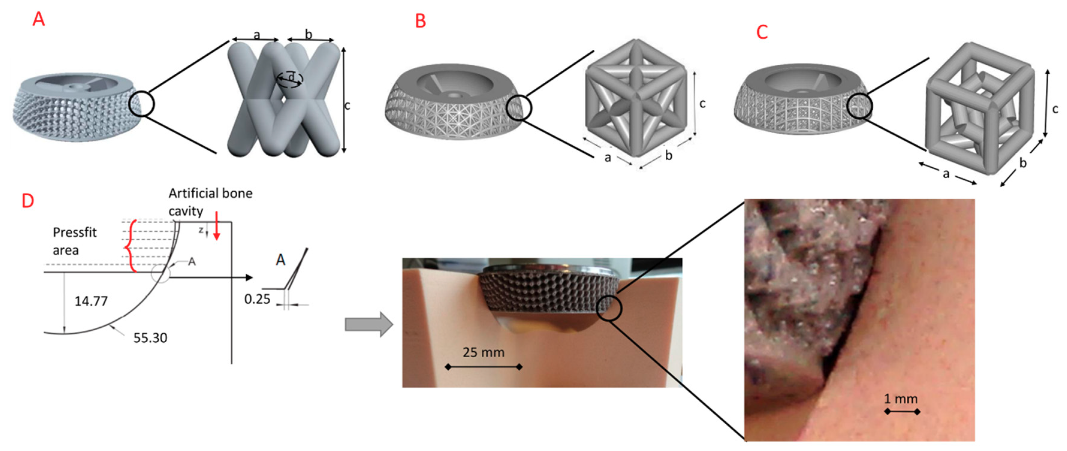
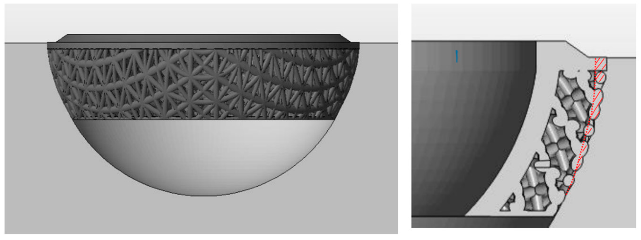
2.1. Cup Design
2.2. Fabrication
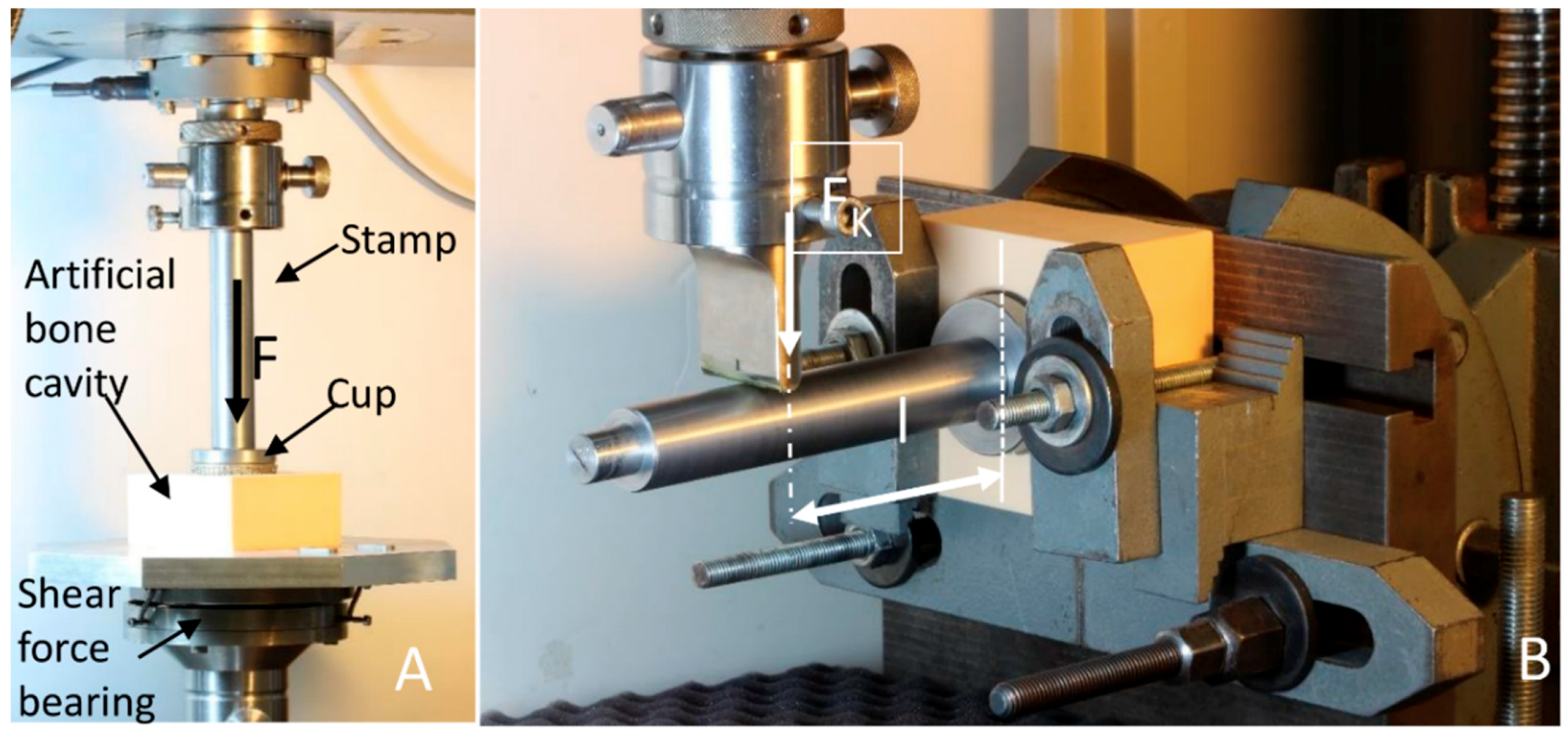
2.3. Measurements
2.4. Statistical Analysis
3. Results and Discussion
3.1. Accuracy of Fabricated Samples
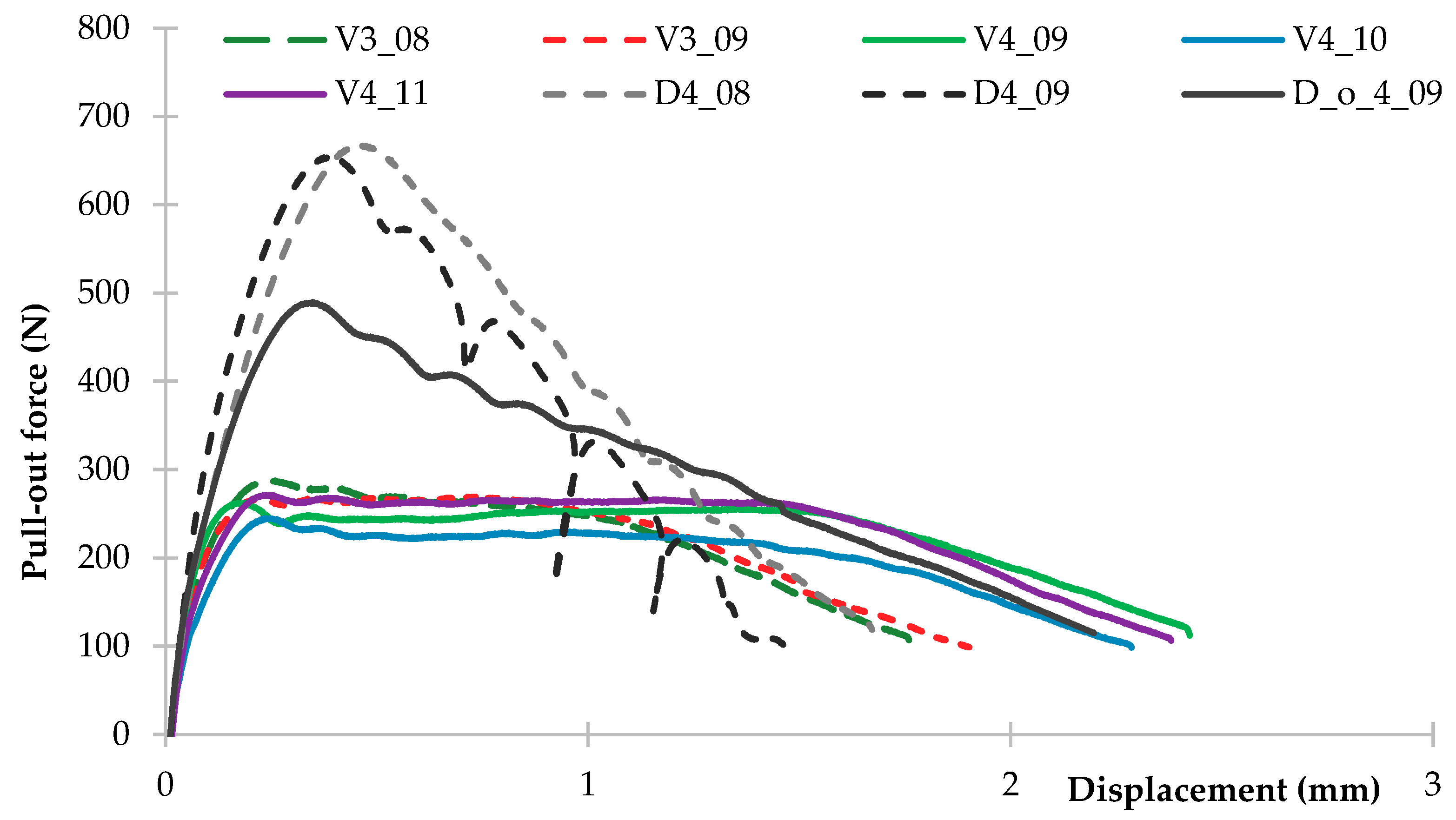
3.2. Pull-Out Force
3.3. Lever-Out Moment
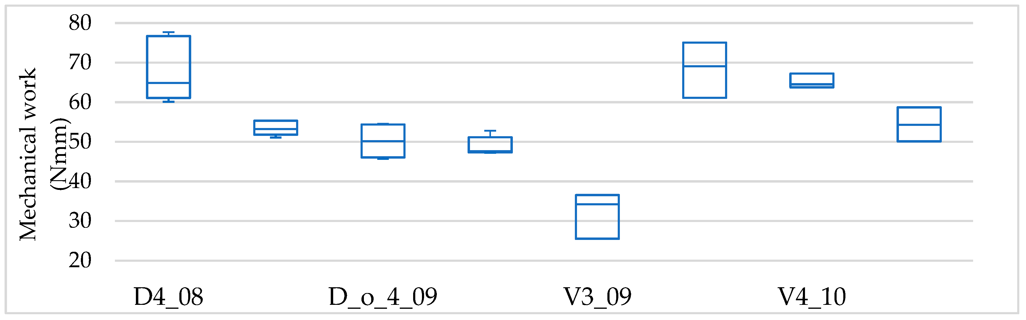
3.4. Lever-Out Momentmechanical Work
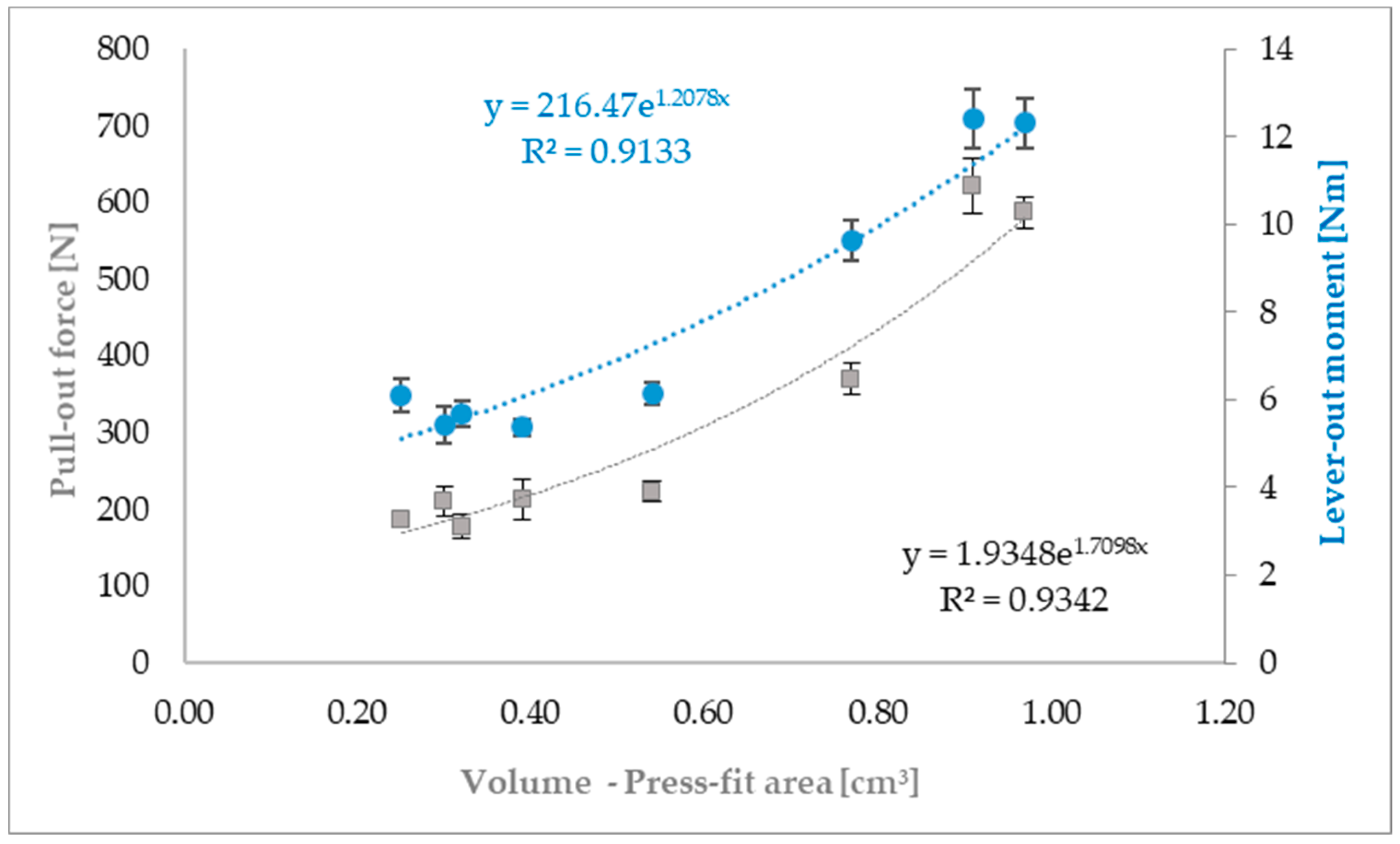
3.5. Correlations—Lever-Out Moment and Pull-Out Force Versus Volume of the Press-Fit Area
4. Conclusions
Author Contributions
Funding
Conflicts of Interest
References
- Harrison, N.; Field, J.R.; Quondamatteo, F.; Curtin, W.; McHugh, P.E.; Mc Donnell, P. Preclinical trial of a novel surface architecture for improved primary fixation of cementless orthopaedic implants. Clin. Biomech. 2014, 29, 861–868. [Google Scholar] [CrossRef] [PubMed]
- Levine, B. A new era in porous metals: Applications in orthopaedics. Adv. Eng. Mater. 2008, 10, 788–792. [Google Scholar] [CrossRef]
- Murr, L.E. Open-cellular metal implant design and fabrication for biomechanical compatibility with bone using electron beam melting. J. Mech. Behav. Biomed. Mater. 2017, 76, 164–177. [Google Scholar] [CrossRef] [PubMed]
- Sing, S.L.; An, J.; Yeong, W.Y.; Wiria, F.E. Laser and electron-beam powder-bed additive manufacturing of metallic implants: A review on processes, materials and designs. J. Orthop. Res. 2016, 34, 369–385. [Google Scholar] [CrossRef] [PubMed]
- Geetha, M.; Singh, A.K.; Asokamani, R.; Gogia, A.K. Ti based biomaterials, the ultimate choice for orthopaedic implants—A review. Prog. Mater. Sci. 2009, 54, 397–425. [Google Scholar] [CrossRef]
- Tan, X.P.; Tan, Y.J.; Chow, C.S.L.; Tor, S.B.; Yeong, W.Y. Metallic powder-bed based 3D printing of cellular scaffolds for orthopaedic implants: A state-of-the-art review on manufacturing, topological design, mechanical properties and biocompatibility. Mater. Sci. Eng. C 2017, 76, 1328–1343. [Google Scholar] [CrossRef] [PubMed]
- Schulze, C.; Weinmann, M.; Schweigel, C.; Keßler, O.; Bader, R. Mechanical Properties of a Newly Additive Manufactured Implant Material Based on Ti-42Nb. Materials 2018, 11, 124. [Google Scholar] [CrossRef] [PubMed]
- Murr, L.E.; Amato, K.N.; Li, S.J.; Tian, Y.X.; Cheng, X.Y.; Gaytan, S.M.; Martinez, E.; Shindo, P.W.; Medina, F.; Wicker, R.B. Microstructure and mechanical properties of open-cellular biomaterials prototypes for total knee replacement implants fabricated by electron beam melting. J. Mech. Behav. Biomed. Mater. 2011, 4, 1396–1411. [Google Scholar] [CrossRef] [PubMed]
- Do Prado, R.F.; De Oliveira, F.S.; Nascimento, R.D.; De Vasconcellos, L.M.R.; Carvalho, Y.R.; Cairo, C.A.A. Osteoblast response to porous titanium and biomimetic surface: In vitro analysis. Mater. Sci. Eng. C 2015, 52, 194–203. [Google Scholar] [CrossRef] [PubMed]
- Wang, X.; Zhou, S.; Xu, W.; Leary, M.; Choong, P.; Qian, M.; Brandt, M.; Xie, Y.M.; Xu, S. Topological design and additive manufacturing of porous metals for bone scaffolds and orthopaedic implants: A review. Biomaterials 2016, 83, 14. [Google Scholar] [CrossRef] [PubMed]
- Limmahakhun, S.; Oloyede, A.; Sitthiseripratip, K.; Xiao, Y.; Yan, C. Stiffness and strength tailoring of cobalt chromium graded cellular structures for stress-shielding reduction. Mater. Des. 2017, 114, 633–641. [Google Scholar] [CrossRef]
- Simoneau, C.; Terriault, P.; Jetté, B.; Dumas, M.; Brailovski, V. Development of a porous metallic femoral stem: Design, manufacturing, simulation and mechanical testing. Mater. Des. 2017, 114, 546–556. [Google Scholar] [CrossRef]
- Kumar, A.; Nune, K.C.; Murr, L.E.; Misra, R.D.K. Biocompatibility and mechanical behaviour of three-dimensional scaffolds for biomedical devices: Process-structure-property paradigm. Int. Mater. Rev. 2016, 61, 20–45. [Google Scholar] [CrossRef]
- Harrison, N.; McHugh, P.E.; Curtin, W.; Mc Donnell, P. Micromotion and friction evaluation of a novel surface architecture for improved primary fixation of cementless orthopaedic implants. J. Mech. Behav. Biomed. Mater. 2013, 21, 37–46. [Google Scholar] [CrossRef] [PubMed]
- Jetté, B.; Brailovski, V.; Dumas, M.; Simoneau, C.; Terriault, P. Femoral stem incorporating a diamond cubic lattice structure: Design, manufacture and testing. J. Mech. Behav. Biomed. Mater. 2018, 77, 58–72. [Google Scholar] [CrossRef] [PubMed]
- Marin, E.; Fusi, S.; Pressacco, M.; Paussa, L.; Fedrizzi, L. Characterization of cellular solids in Ti6Al4V for orthopaedic implant applications: Trabecular titanium. J. Mech. Behav. Biomed. Mater. 2010, 3, 373–381. [Google Scholar] [CrossRef] [PubMed]
- Le Guéhennec, L.; Soueidan, A.; Layrolle, P.; Amouriq, Y. Surface treatments of titanium dental implants for rapid osseointegration. Dent. Mater. 2007, 23, 844–854. [Google Scholar] [CrossRef] [PubMed]
- Khanna, R.; Kokubo, T.; Matsushita, T.; Nomura, Y.; Nose, N.; Oomori, Y.; Yoshida, T.; Wakita, K.; Takadama, H. Novel artificial hip joint: A layer of alumina on Ti-6Al-4V alloy formed by micro-arc oxidation. Mater. Sci. Eng. C 2015, 55, 393–400. [Google Scholar] [CrossRef] [PubMed]
- Ramsden, J.J.; Allen, D.M.; Stephenson, D.J.; Alcock, J.R.; Peggs, G.N.; Fuller, G.; Goch, G. The design and manufacture of biomedical surface. CIRP Ann. Manuf. Technol. 2007, 56, 687–711. [Google Scholar] [CrossRef]
- Emmelmann, C.; Scheinemann, P.; Munsch, M.; Seyda, V. Laser additive manufacturing of modified implant surfaces with osseointegrative characteristics. Phys. Procedia 2011, 12, 375–384. [Google Scholar] [CrossRef]
- Paris, M.; Götz, A.; Hettrich, I.; Bidan, C.M.; Dunlop, J.W.C.; Razi, H.; Zizak, I.; Hutmacher, D.W.; Fratzl, P.; Duda, G.N.; et al. Scaffold curvature-mediated novel biomineralization process originates a continuous soft tissue-to-bone interface. Acta Biomater. 2017, 60, 64–80. [Google Scholar] [CrossRef] [PubMed]
- Wang, Z.; Wang, C.; Li, C.; Qin, Y.; Zhong, L.; Chen, B.; Li, Z.; Liu, H.; Chang, F.; Wang, J. Analysis of factors influencing bone ingrowth into three-dimensional printed porous metal scaffolds: A review. J. Alloys Compd. 2017, 717, 271–285. [Google Scholar] [CrossRef]
- Schouman, T.; Schmitt, M.; Adam, C.; Dubois, G.; Rouch, P. Influence of the overall stiffness of a load-bearing porous titanium implant on bone ingrowth in critical-size mandibular bone defects in sheep. J. Mech. Behav. Biomed. Mater. 2016, 59, 484–496. [Google Scholar] [CrossRef] [PubMed]
- de Wild, M.; Zimmermann, S.; Rüegg, J.; Schumacher, R.; Fleischmann, T.; Ghayor, C.; Weber, F.E. Influence of microarchitecture on osteoconduction and mechanics of porous titanium Scaffolds generated by selective laser melting. 3D Print. Addit. Manuf. 2016, 3, 142–151. [Google Scholar] [CrossRef]
- Taniguchi, N.; Fujibayashi, S.; Takemoto, M.; Sasaki, K.; Otsuki, B. Effect of pore size on bone ingrowth into porous titanium implants. Mater. Sci. Eng. C 2016, 59, 690–701. [Google Scholar] [CrossRef] [PubMed]
- Jetté, B.; Brailovski, V.; Simoneau, C.; Dumas, M.; Terriault, P. Development and in vitro validation of a simplified numerical model for the design of a biomimetic femoral stem. J. Mech. Behav. Biomed. Mater. 2017, 77, 539–550. [Google Scholar] [CrossRef] [PubMed]
- Bellini, C.M.; Galbusera, F.; Ceroni, R.G.; Raimondi, M.T. Loss in mechanical contact of cementless acetabular prostheses due to post-operative weight bearing: A biomechanical model. Med. Eng. Phys. 2007, 29, 175–181. [Google Scholar] [CrossRef] [PubMed]
- Souffrant, R.; Zietz, C.; Fritsche, A.; Kluess, D.; Mittelmeier, W.; Bader, R. Advanced material modelling in numerical simulation of primary acetabular press-fit cup stability. Comput. Methods Biomech. Biomed. Engin. 2012, 15, 787–793. [Google Scholar] [CrossRef] [PubMed]
- Small, S.R.; Berend, M.E.; Howard, L.A.; Rogge, R.D.; Buckley, C.A.; Ritter, M.A. High initial stability in porous titanium acetabular cups: A biomechanical study. J. Arthroplast. 2013, 28, 510–516. [Google Scholar] [CrossRef] [PubMed]
- Udofia, I.; Liu, F.; Jin, Z.; Roberts, P.; Grigoris, P. The initial stability and contact mechanics of a press-fit resurfacing arthroplasty of the hip. J. Bone Jt. Surg. Br. 2007, 89, 549–556. [Google Scholar] [CrossRef] [PubMed]
- Chang, J.-D.; Kim, T.-Y.; Rao, M.B.; Lee, S.-S.; Kim, I.-S. Revision total hip arthroplasty using a tapered, press-fit cementless revision stem in elderly patients. J. Arthroplast. 2011, 26, 1045–1049. [Google Scholar] [CrossRef] [PubMed]
- Chanlalit, C.; Fitzsimmons, J.S.; Shukla, D.R.; An, K.-N.; O’Driscoll, S.W. Micromotion of plasma spray versus grit-blasted radial head prosthetic stem surfaces. J. Shoulder Elb. Surg. 2011, 20, 717–722. [Google Scholar] [CrossRef] [PubMed]
- Le Cann, S.; Galland, A.; Rosa, B.; Le Corroller, T.; Pithioux, M.; Argenson, J.N.; Chabrand, P.; Parratte, S. Does surface roughness influence the primary stability of acetabular cups? A numerical and experimental biomechanical evaluation. Med. Eng. Phys. 2014, 36, 1185–1190. [Google Scholar] [CrossRef] [PubMed]
- Goriainov, V.; Jones, A.; Briscoe, A.; New, A.; Dunlop, D. Do the cup surface properties influence the initial stability? J. Arthroplast. 2014, 29, 757–762. [Google Scholar] [CrossRef] [PubMed]
- Gebert, A.; Peters, J.; Bishop, N.E.; Westphal, F.; Morlock, M.M. Influence of press-fit parameters on the primary stability of uncemented femoral resurfacing implants. Med. Eng. Phys. 2009, 31, 160–164. [Google Scholar] [CrossRef] [PubMed]
- Ries, M.D.; Harbaugh, M.; Shea, J.; Lambert, R. Effect of cementless acetabular cup geometry on strain distribution and press-fit stability. J. Arthroplast. 1997, 12, 207–212. [Google Scholar] [CrossRef]
- Adler, E.; Stuchin, S.A.; Kummer, F.J. Stability of press-fit acetabular cups. J. Arthroplast. 1992, 7, 295–301. [Google Scholar] [CrossRef]
- Macdonald, W.; Carlsson, L.V.; Charnley, G.J.; Jacobsson, C.M. Press-fit acetabular cup fixation: Principles and testing. Proc. Inst. Mech. Eng. Part H J. Eng. Med. 1999, 213, 33–39. [Google Scholar] [CrossRef] [PubMed]
- Morlock, M.; Götzen, N.; Sellenschloh, K. Bestimmung der Primärstabilität von künstlichen Hüftpfannen. In DVM Bericht 314—Eigenschaften und Prüftechniken mechanisch Beanspruchter Implantate; DVM: Berlin, Germany, 2002; pp. 221–229. [Google Scholar]
- Toossi, N.; Adeli, B.; Timperley, A.J.; Haddad, F.S.; Maltenfort, M.; Parvizi, J. Acetabular components in total hip arthroplasty: Is there evidence that cementless fixation is better? J. Bone Jt. Surg. 2013, 95, 168–174. [Google Scholar] [CrossRef] [PubMed]
- Roth, A.; Winzer, T.; Sander, K.; Anders, J.O.; Venbrocks, R.-A. Press fit fixation of cementless cups: How much stability do we need indeed? Arch. Orthop. Trauma Surg. 2006, 126, 77–81. [Google Scholar] [CrossRef] [PubMed]
- Tabata, T.; Kaku, N.; Hara, K.; Tsumura, H. Initial stability of cementless acetabular cups: Press-fit and screw fixation interaction—An in vitro biomechanical study. Eur. J. Orthop. Surg. Traumatol. 2015, 25, 497–502. [Google Scholar] [CrossRef] [PubMed]
- Takao, M.; Nakamura, N.; Ohzono, K.; Sakai, T.; Nishii, T.; Sugano, N. The results of a press-fit-only technique for acetabular fixation in hip dysplasia. J. Arthroplast. 2011, 26, 562–568. [Google Scholar] [CrossRef] [PubMed]
- Amirouche, F.; Solitro, G.; Broviak, S.; Gonzalez, M.; Goldstein, W.; Barmada, R. Factors influencing initial cup stability in total hip arthroplasty. Clin. Biomech. 2014, 29, 1177–1185. [Google Scholar] [CrossRef] [PubMed]
- Clarke, H.J.; Jinnah, R.H.; Warden, K.E.; Cox, Q.G.; Curtis, M.J. Evaluation of acetabular stability in uncemented prostheses. J. Arthroplast. 1991, 6, 335–340. [Google Scholar] [CrossRef]
- Klanke, J.; Partenheimer, A.; Westermann, K. Biomechanical qualities of threaded acetabular cups. Int. Orthop. 2002, 26, 278–282. [Google Scholar] [CrossRef] [PubMed]
- Baleani, M.; Fognani, R.; Toni, A. Initial stability of a cementless acetabular cup design: Experimental investigation on the effect of adding fins to the rim of the cup. Artif. Organs. 2001, 25, 664–669. [Google Scholar] [CrossRef] [PubMed]
- Olory, B.; Havet, E.; Gabrion, A.; Vernois, J.; Mertl, P. Comparative in vitro assessment of the primay stbility of cementless press-fit acetabular cups. Acta Orthop. Belg. 2004, 70, 31–37. [Google Scholar] [PubMed]
- Fritsche, A.; Zietz, C.; Teufel, S.; Kolp, W.; Tokar, I.; Mauch, C.; Mittelmeier, W.; Bader, R. In-vitro and in-vivo investigations of the impaction and pull-out behavior of metal-backed acetabular cups. Br. Ed. Soc. Bone Jt. Surg. 2011, 93, 406. [Google Scholar]
- Weißmann, V.; Boss, C.; Bader, R.; Hansmann, H. A novel approach to determine primary stability of acetabular press-fit cups. J. Mech. Behav. Biomed. Mater. 2018, 80, 1–10. [Google Scholar] [CrossRef] [PubMed]
- Markhoff, J.; Wieding, J.; Weissmann, V.; Pasold, J.A.; Jonitz-Heincke, R. Bader, Influence of different three-dimensional open porous titanium scaffold designs on human osteoblasts behavior in static and dynamic cell investigations. Materials 2015, 8, 5490–5507. [Google Scholar] [CrossRef] [PubMed]
- Weißmann, V.; Bader, R.; Hansmann, H.; Laufer, N. Influence of the structural orientation on the mechanical properties of selective laser melted Ti6Al4V open-porous scaffolds. Mater. Des. 2016, 95, 188–197. [Google Scholar] [CrossRef]
- Weißmann, V.; Wieding, J.; Hansmann, H.; Laufer, N.; Wolf, A.; Bader, R. Specific yielding of selective laser-melted Ti6Al4V open-porous scaffolds as a function of unit cell design and dimensions. Metals 2016, 6, 166. [Google Scholar] [CrossRef]
- Weißmann, V.; Hansmann, H.; Bader, R.; Laufer, N. Influence of the Structural Orientation on the Mechanical Properties of Selective Laser Melted TiAL6V4 Open-Porous Scaffold. In Proceedings of the 13th Rapid Tech Conference Erfurt, Erfurt, Germany, 14–16 June 2016. [Google Scholar]
- Fox, J.C.; Moylan, S.P.; Lane, B.M. Effect of process parameters on the surface roughness of overhanging structures in laser powder bed fusion additive manufacturing. Procedia CIRP 2016, 45, 131–134. [Google Scholar] [CrossRef]
- Rashed, M.G.; Ashraf, M.; Mines, R.A.W.; Hazell, P.J. Metallic microlattice materials: A current state of the art on manufacturing, mechanical properties and applications. Mater. Des. 2016, 95, 518–533. [Google Scholar] [CrossRef]
- Suard, M.; Martin, G.; Lhuissier, P.; Dendievel, R.; Vignat, F.; Blandin, J.J.; Villeneuve, F. Mechanical equivalent diameter of single struts for the stiffness prediction of lattice structures produced by Electron Beam Melting. Addit. Manuf. 2015, 8, 124–131. [Google Scholar] [CrossRef]
- Weißmann, V.; Drescher, P.; Bader, R.; Seitz, H.; Hansmann, H.; Laufer, N. Comparison of single Ti6Al4V struts made using selective laser melting and electron beam melting subject to part orientation. Metals 2017, 7, 91. [Google Scholar] [CrossRef]
- Triantaphyllou, A.; Giusca, C.L.; Macaulay, G.D.; Roerig, F.; Hoebel, M.; Leach, R.K.; Tomita, B.; Milne, K.A. Surface texture measurement for additive manufacturing. Surf. Topogr. Metrol. Prop. 2015, 3, 024002. [Google Scholar] [CrossRef]
- Frosch, K.; Barvencik, F.; Viereck, V.; Lohmann, C.H.; Dresing, K.; Breme, J.; Brunner, E.; Stürmer, K.M. Growth behavior, matrix production, and gene expression of human osteoblasts in defined cylindrical titanium channels. J. Biomed. Mater. Res. Part A 2004, 68, 325–334. [Google Scholar] [CrossRef] [PubMed]
- Knychala, J.; Bouropoulos, N.; Catt, C.J.; Katsamenis, O.L.; Please, C.P.; Sengers, B.G. Pore geometry regulates early stage human bone marrow cell tissue formation and organization. Ann. Biomed. Eng. 2013, 41, 917–930. [Google Scholar] [CrossRef] [PubMed]
- Kienapfel, H.; Sprey, C.; Wilke, A.; Griss, P. Implant fixation by bone ingrowth. J. Arthroplast. 1999, 14, 355–368. [Google Scholar] [CrossRef]
- Kawai, T.; Takemoto, M.; Fujibayashi, S.; Tanaka, M.; Akiyama, H.; Nakamura, T.; Matsuda, S. Comparison between alkali heat treatment and sprayed hydroxyapatite coating on thermally-sprayed rough Ti surface in rabbit model: Effects on bone-bonding ability and osteoconductivity. J. Biomed. Mater. Res. Part B Appl. Biomater. 2015, 103, 1069–1081. [Google Scholar] [CrossRef] [PubMed]
- Grimal, Q.; Haupert, S.; Mitton, D.; Vastel, L.; Laugier, P. Assessment of cortical bone elasticity and strength: Mechanical testing and ultrasound provide complementary data. Med. Eng. Phys. 2009, 31, 1140–1147. [Google Scholar] [CrossRef] [PubMed]
- Niinomi, M.; Nakai, M. Titanium-based biomaterials for preventing stress shielding between implant devices and bone. Int. J. Biomater. 2011, 2011. [Google Scholar] [CrossRef] [PubMed]
- Wauthle, R.; Vrancken, B.; Beynaerts, B.; Jorissen, K.; Schrooten, J.; Kruth, J.-P.; Humbeeck, J. Effects of build orientation and heat treatment on the microstructure and mechanical properties of selective laser melted Ti6Al4 V lattice structures. Addit. Manuf. 2014, 5, 6–13. [Google Scholar] [CrossRef]
- Goldman, A.H.; Armstrong, L.C.; Owen, J.R.; Wayne, J.S.; Jiranek, W.A. Does increased coefficient of friction of highly porous metal increase initial stability at the acetabular interface? J. Arthroplast. 2016, 31, 721–726. [Google Scholar] [CrossRef] [PubMed]
- Ahmadi, S.M.; Campoli, G.; Amin Yavari, S.; Sajadi, B.; Wauthle, R.; Schrooten, J.; Weinans, H.; Zadpoor, A.A. Mechanical behavior of regular open-cell porous biomaterials made of diamond lattice unit cells. J. Mech. Behav. Biomed. Mater. 2014, 34, 106–115. [Google Scholar] [CrossRef] [PubMed]
- Lopez-Heredia, M.A.; Goyenvalle, E.; Aguado, E.; Pilet, P.; Leroux, C.; Dorget, M.; Weiss, P.; Layrolle, P. Bone growth in rapid prototyped porous titanium implants. J. Biomed. Mater. Res. Part A 2008, 85, 664–673. [Google Scholar] [CrossRef] [PubMed]
- Hedayati, R.; Sadighi, M.; Mohammadi-Aghdam, M.; Zadpoor, A.A. Mechanics of additively manufactured porous biomaterials based on the rhombicuboctahedron unit cell. J. Mech. Behav. Biomed. Mater. 2016, 53, 272–294. [Google Scholar] [CrossRef] [PubMed]
- Gollwitzer, R.; Gradinger, H. Ossäre Integration; Springer Medizin Verlag: Heidelberg, Germany, 2006. [Google Scholar]
- Swarts, E.; Bucher, T.A.; Phillips, M.; Yap, F.H.X. Does the ingrowth surface make a difference? A retrieval study of 423 cementless acetabular components. J. Arthroplast. 2015, 30, 706–712. [Google Scholar] [CrossRef] [PubMed]


| Unit Cell | Twisted (V) | Combined (D) | Combined Open (D_o) | |||||
|---|---|---|---|---|---|---|---|---|
 |  |  | ||||||
| Dimension | V4_09 | V4_10 | V4_11 | V3_09 | V3_08 | D4_09 | D4_08 | D_o_4_09 |
| Width-a (mm) | 2.83 | 2.83 | 2.83 | 2.12 | 2.12 | 4.00 | 4.00 | 4.00 |
| Depth-b (mm) | 2.83 | 2.83 | 2.83 | 2.12 | 2.12 | 4.00 | 4.00 | 4.00 |
| Height-c (mm) | 4.00 | 4.00 | 4.00 | 3.00 | 3.00 | 4.00 | 4.00 | 4.00 |
| Strut diameter-d (mm) | 0.90 | 1.00 | 1.10 | 0.90 | 0.80 | 0.90 | 0.80 | 0.90 |
| Porosity-Structure area (%) | 72.50 | 67.40 | 60.60 | 58.80 | 65.50 | 61.10 | 66.90 | 74.80 |
| Volume-Press-fit area (cm3) | 0.30 | 0.39 | 0.25 | 0.32 | 0.54 | 0.97 | 0.91 | 0.77 |
| Parameter | Description | Unit | Process Parameter |
|---|---|---|---|
| P | Laser power | W | 275 |
| v | Scan speed | mm/s | 805 |
| d | Hatch spacing | µm | 120 |
| t | Layer thickness | µm | 50 |
| Name | Press-Fit Cup | Artificial Bone Cavity | Press-Fit (mm) | ||
|---|---|---|---|---|---|
| Best Fit Circle (mm) | Roundness (mm) | Best Fit Circle (mm) | Roundness (mm) | ||
| V3_08 | 55.32 | 0.26 | 53.18 ± 0.02 | 0.14 ± 0.02 | 2.13 ± 0.02 |
| V3_09 | 55.47 | 0.17 | 53.34 ± 0.02 | 0.13 ± 0.04 | 2.13 ± 0.01 |
| V4_09 | 54.90 | 0.29 | 52.68 ± 0.01 | 0.15 ± 0.01 | 2.16 ± 0.01 |
| V4_10 | 55.03 | 0.02 | 52.87 ± 0.01 | 0.14 ± 0.02 | 2.15 ± 0.01 |
| V4_11 | 55.20 | 0.28 | 53.07 ± 0.01 | 0.12 ± 0.01 | 2.13 ± 0.01 |
| D4_08 | 54.98 | 0.30 | 52.87 ± 0.01 | 0.14 ± 0.01 | 2.11 ± 0.01 |
| D4_09 | 55.04 | 0.11 | 52.87 ± 0.01 | 0.14 ± 0.01 | 2.17 ± 0.01 |
| D_o_4_09 | 55.03 | 0.25 | 52.87 ± 0.01 | 0.14 ± 0.01 | 2.16 ± 0.01 |
| Cupversion | D4_09 | D_o_4_09 | V3_08 | V3_09 | V4_09 | V4_10 | V4_11 |
|---|---|---|---|---|---|---|---|
| D4_08 | N.S. | 0.00438 | <0.001 | <0.001 | <0.001 | <0.001 | <0.001 |
| D4_09 | - | 0.00193 | <0.001 | <0.001 | <0.001 | <0.001 | <0.001 |
| D_o_4_09 | - | - | <0.001 | 0.0006 | <0.001 | <0.001 | <0.001 |
| V3_08 | - | - | - | N.S. | N.S. | 0.0242 | N.S. |
| V3_09 | - | - | - | - | N.S. | N.S. | N.S. |
| V4_09 | - | - | - | - | - | N.S. | N.S. |
| V4_10 | - | - | - | - | - | - | N.S. |
| Cupversion | D4_09 | D_o_4_09 | V3_08 | V3_09 | V4_09 | V4_10 | V4_11 |
|---|---|---|---|---|---|---|---|
| D4_08 | N.S. | <0.001 | <0.001 | <0.001 | <0.001 | <0.001 | <0.001 |
| D4_09 | - | <0.001 | <0.001 | <0.001 | <0.001 | <0.001 | <0.001 |
| D_o_4_09 | - | - | <0.001 | <0.001 | <0.001 | <0.001 | <0.001 |
| V3_08 | - | - | - | 0.04619 | N.S. | N.S. | 0.04649 |
| V3_09 | - | - | - | - | N.S. | N.S. | N.S. |
| V4_09 | - | - | - | - | - | N.S. | N.S. |
| V4_10 | - | - | - | - | - | - | N.S. |
| Cupversion | D4_09 | D_o_4_09 | V3_08 | V3_09 | V4_09 | V4_10 | V4_11 |
|---|---|---|---|---|---|---|---|
| D4_08 | N.S. | N.S. | N.S. | 0.04296 | N.S. | N.S. | N.S. |
| D4_09 | - | N.S. | N.S. | 0.01733 | N.S. | N.S. | N.S. |
| D_o_4_09 | - | - | N.S. | N.S. | N.S. | N.S. | N.S. |
| V3_08 | - | - | - | N.S. | N.S. | N.S. | N.S. |
| V3_09 | - | - | - | - | 0.01595 | 0.03089 | 0.01335 |
| V4_09 | - | - | - | - | - | N.S. | N.S. |
| V4_10 | - | - | - | - | - | - | N.S. |
© 2018 by the authors. Licensee MDPI, Basel, Switzerland. This article is an open access article distributed under the terms and conditions of the Creative Commons Attribution (CC BY) license (http://creativecommons.org/licenses/by/4.0/).
Share and Cite
Weißmann, V.; Boss, C.; Schulze, C.; Hansmann, H.; Bader, R. Experimental Characterization of the Primary Stability of Acetabular Press-Fit Cups with Open-Porous Load-Bearing Structures on the Surface Layer. Metals 2018, 8, 839. https://doi.org/10.3390/met8100839
Weißmann V, Boss C, Schulze C, Hansmann H, Bader R. Experimental Characterization of the Primary Stability of Acetabular Press-Fit Cups with Open-Porous Load-Bearing Structures on the Surface Layer. Metals. 2018; 8(10):839. https://doi.org/10.3390/met8100839
Chicago/Turabian StyleWeißmann, Volker, Christian Boss, Christian Schulze, Harald Hansmann, and Rainer Bader. 2018. "Experimental Characterization of the Primary Stability of Acetabular Press-Fit Cups with Open-Porous Load-Bearing Structures on the Surface Layer" Metals 8, no. 10: 839. https://doi.org/10.3390/met8100839
APA StyleWeißmann, V., Boss, C., Schulze, C., Hansmann, H., & Bader, R. (2018). Experimental Characterization of the Primary Stability of Acetabular Press-Fit Cups with Open-Porous Load-Bearing Structures on the Surface Layer. Metals, 8(10), 839. https://doi.org/10.3390/met8100839