Mechanism of Solder Joint Cracks in Anisotropic Conductive Films Bonding and Solutions: Delaying Hot-Bar Lift-Up Time and Adding Silica Fillers


Abstract
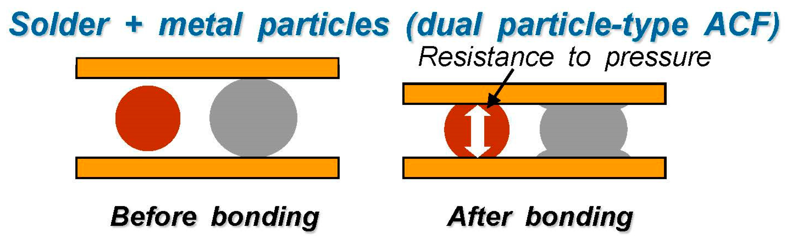
:1. Introduction
2. Experiments
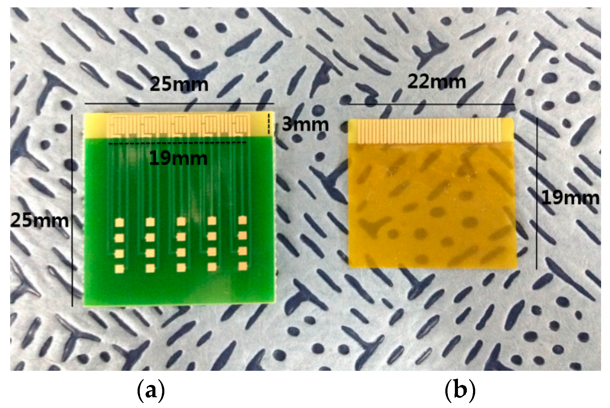
2.1. Test Vehicles and Materials
2.2. Two Bonding Methods
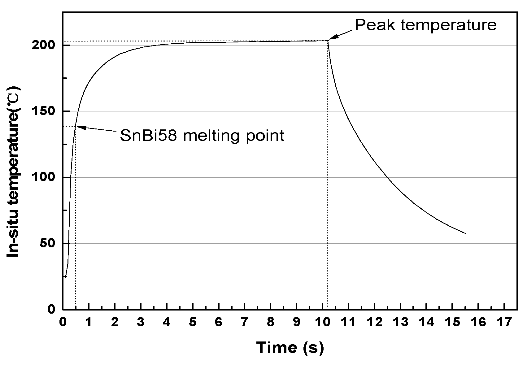
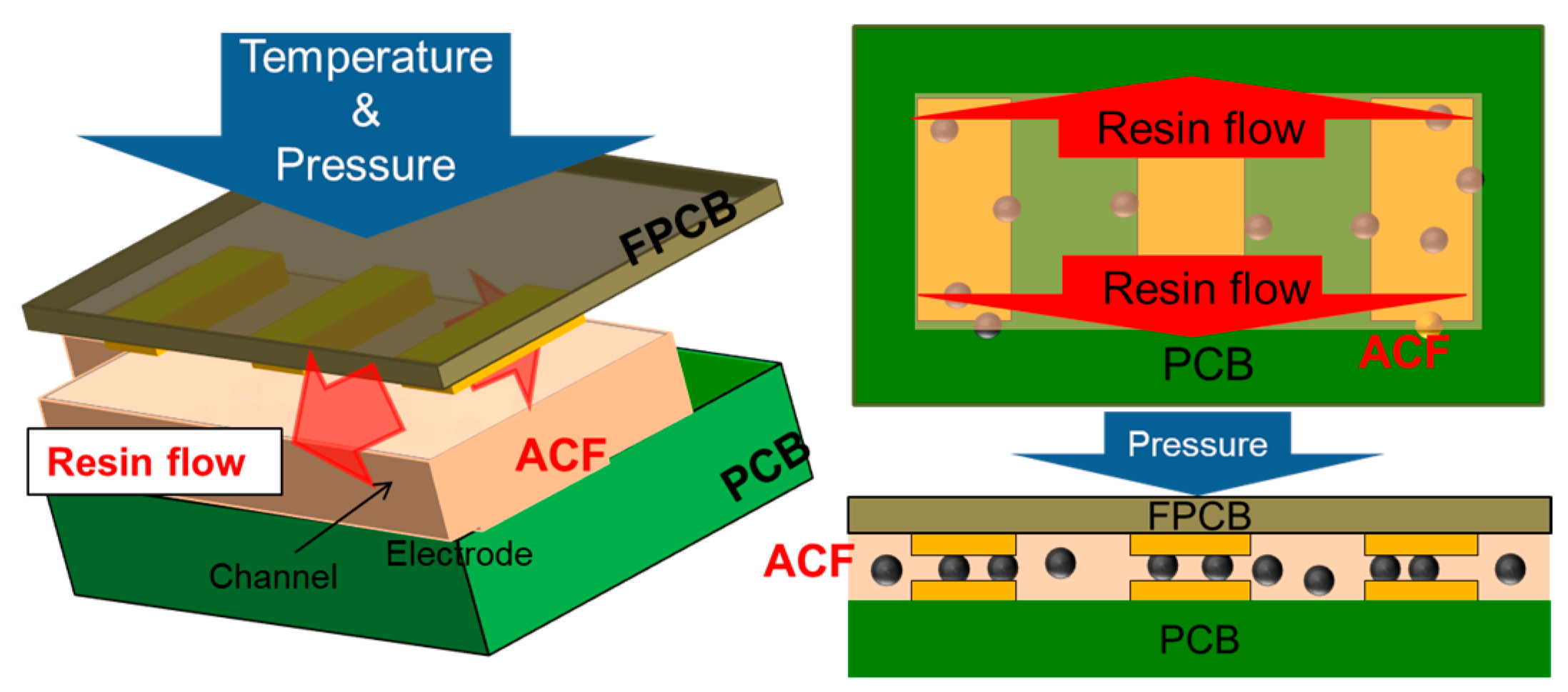
2.2.1. Thermo-Compression Bonding
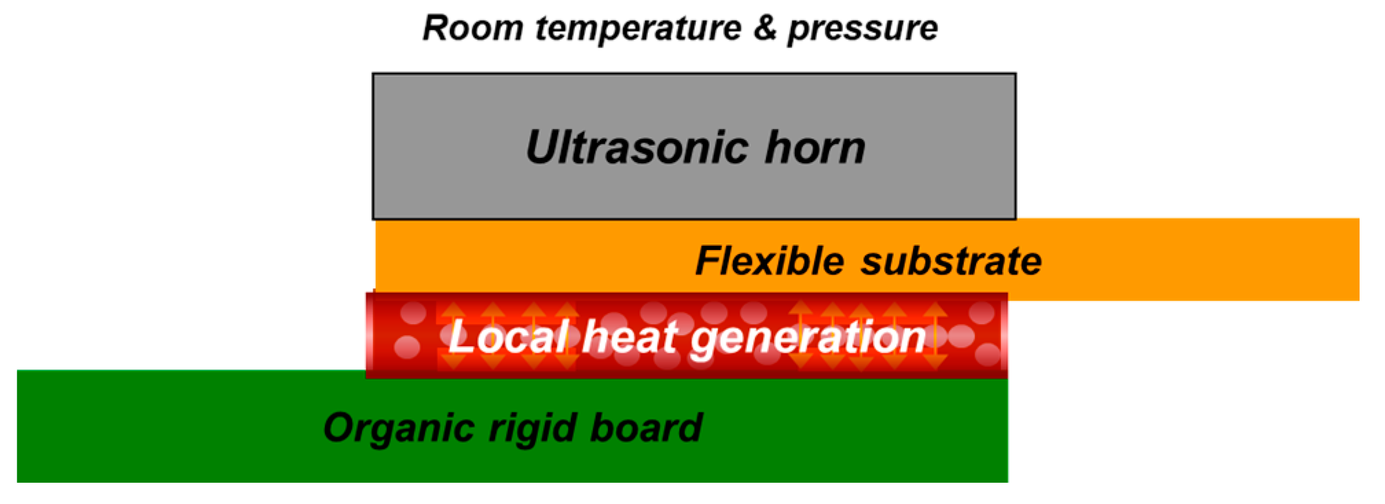
2.2.2. Ultrasonic Bonding
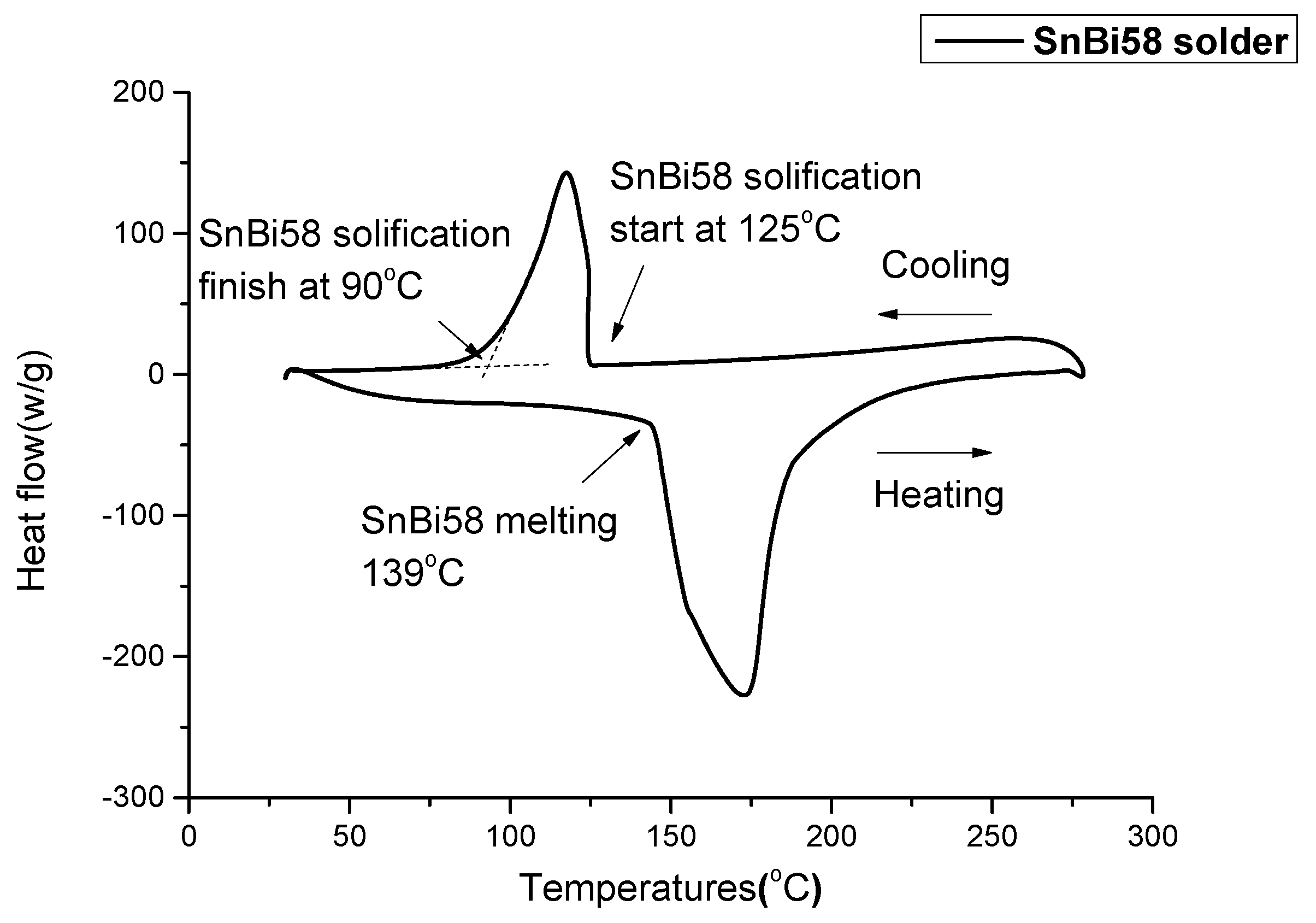
2.3. Differential Scanning Calorimetry (DSC)
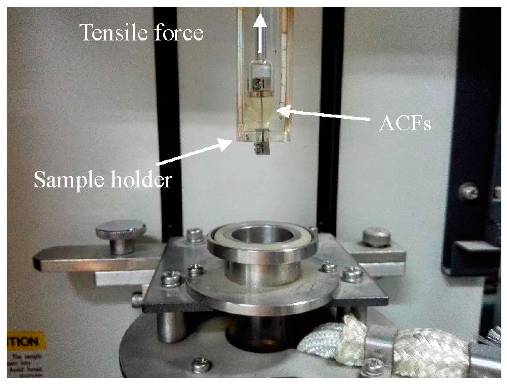
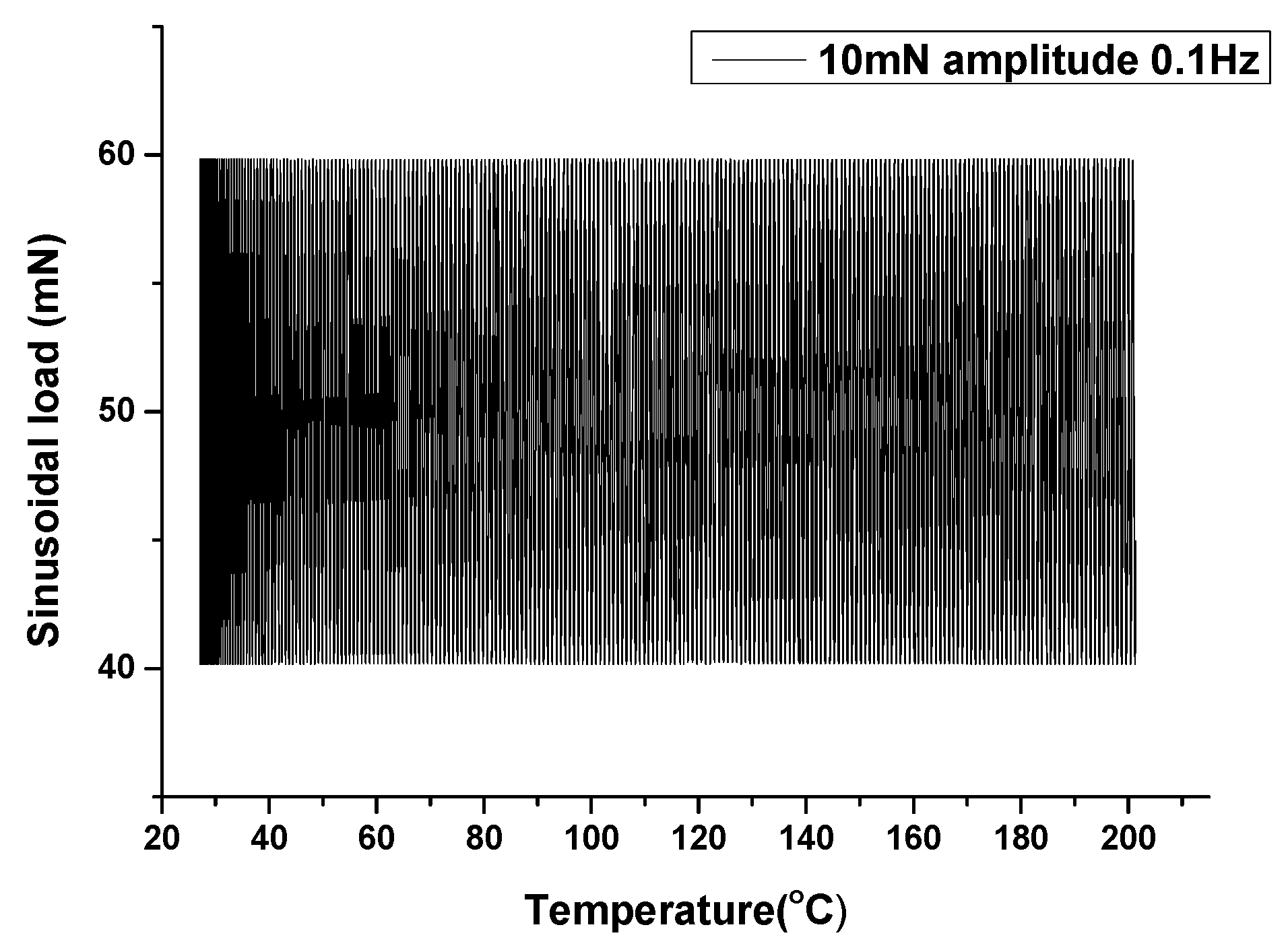
2.4. Thermomechanical Analysis
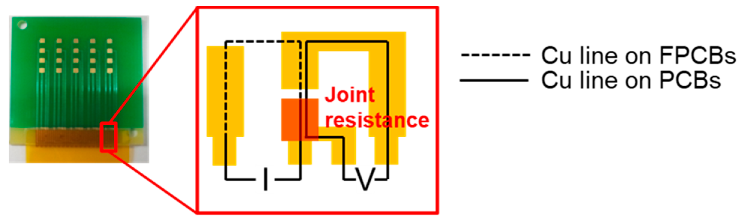
2.5. Joint Resistance and Morphologies
2.6. Reliability Evaluation
3. Results and Discussion
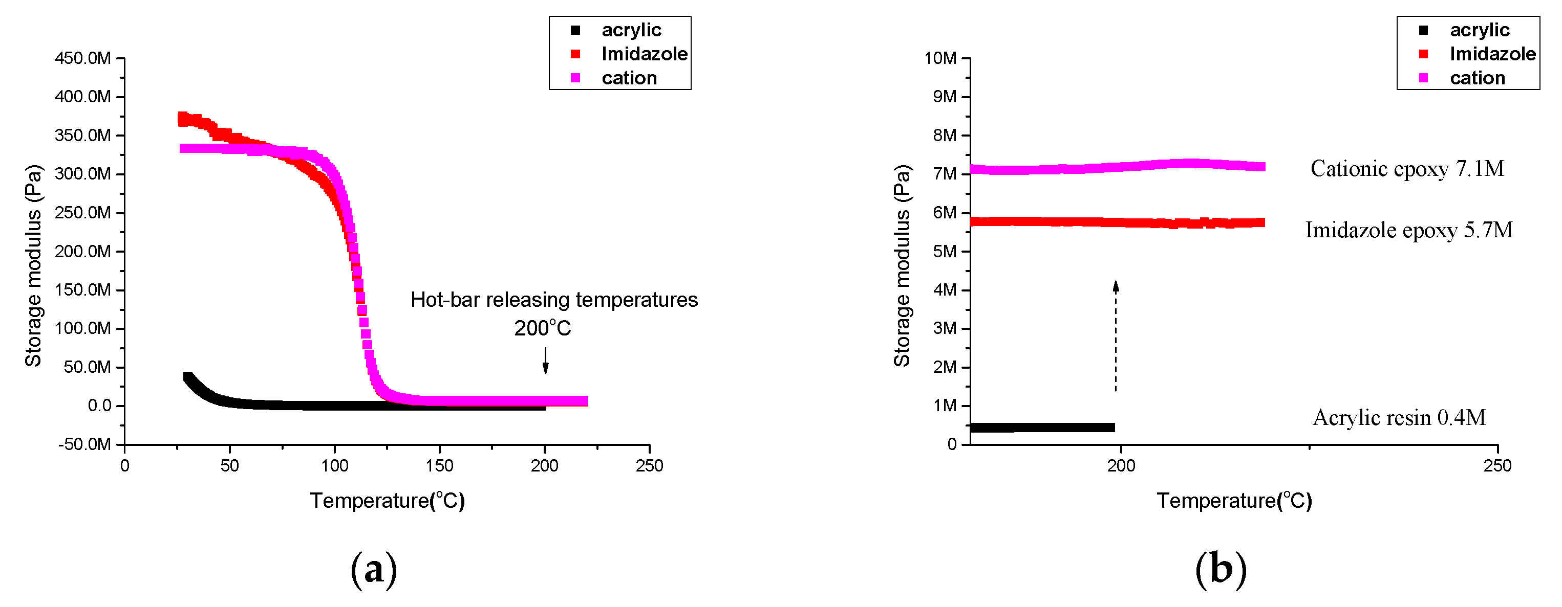
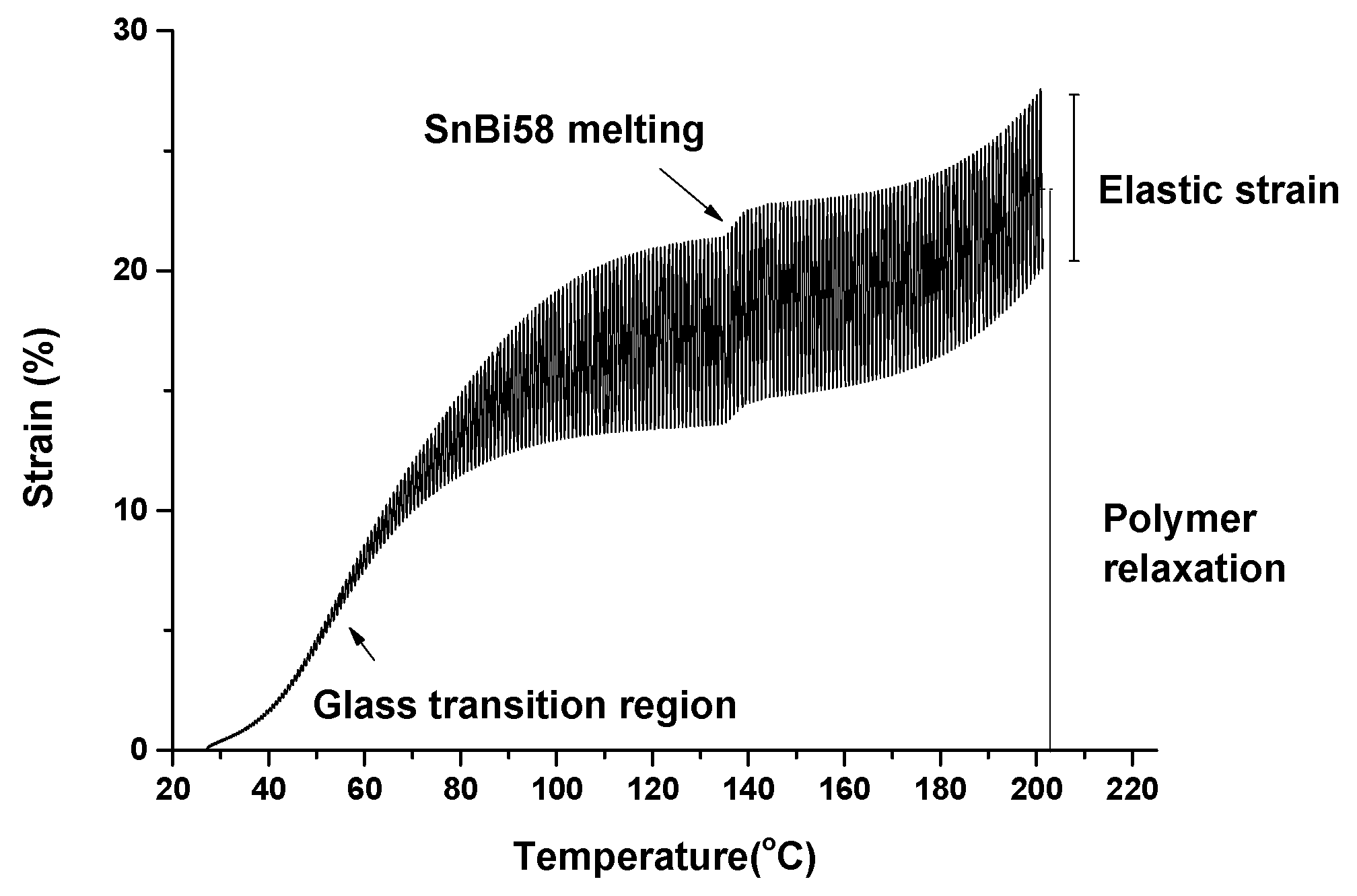
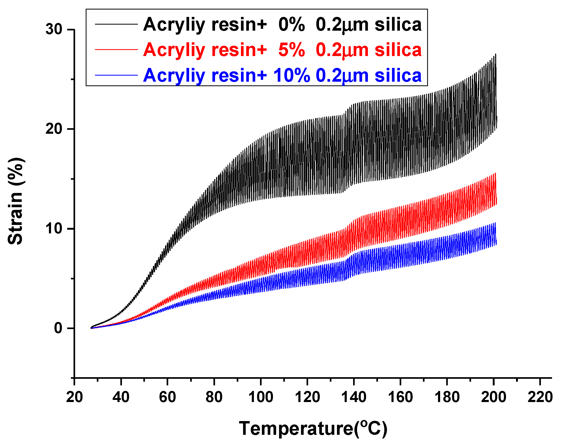
3.1. Elastic Property of Polymer Resin
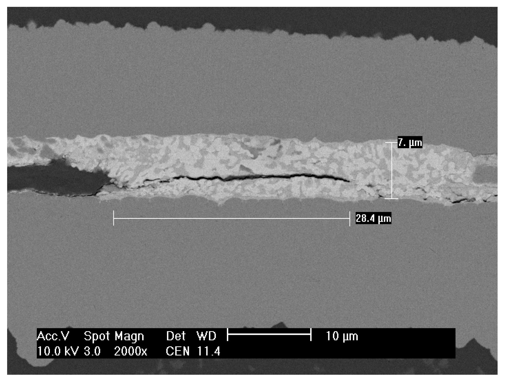
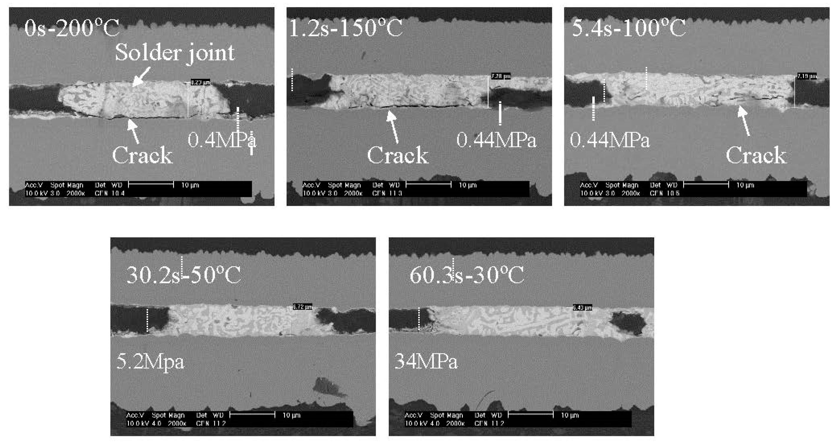
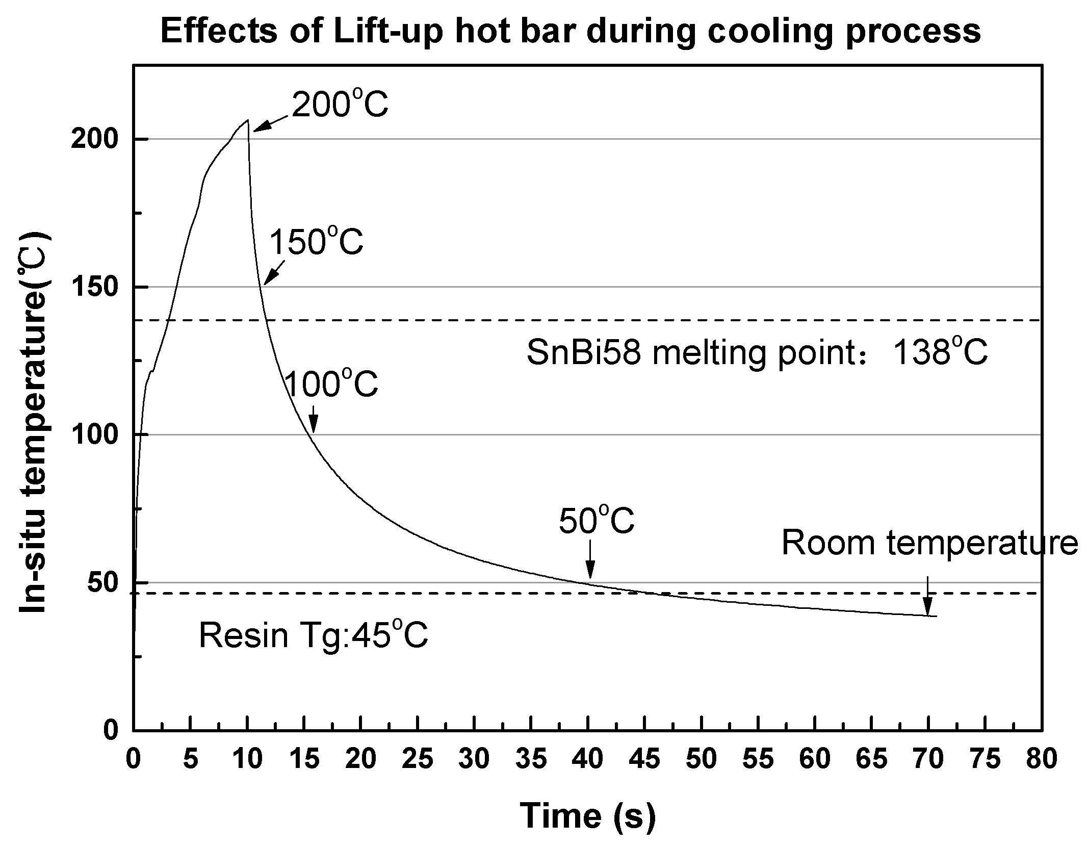
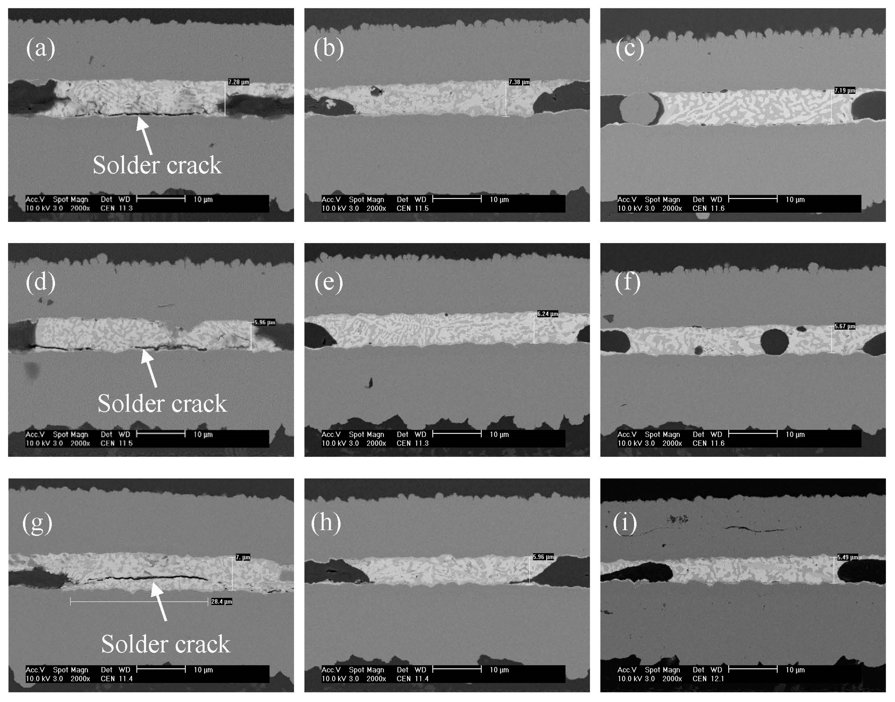
3.2. Effects of Resin Tg on Solder Joint Morphology
3.3. Effects of Ultrasonic Bonding on Increasing Resin Modulus
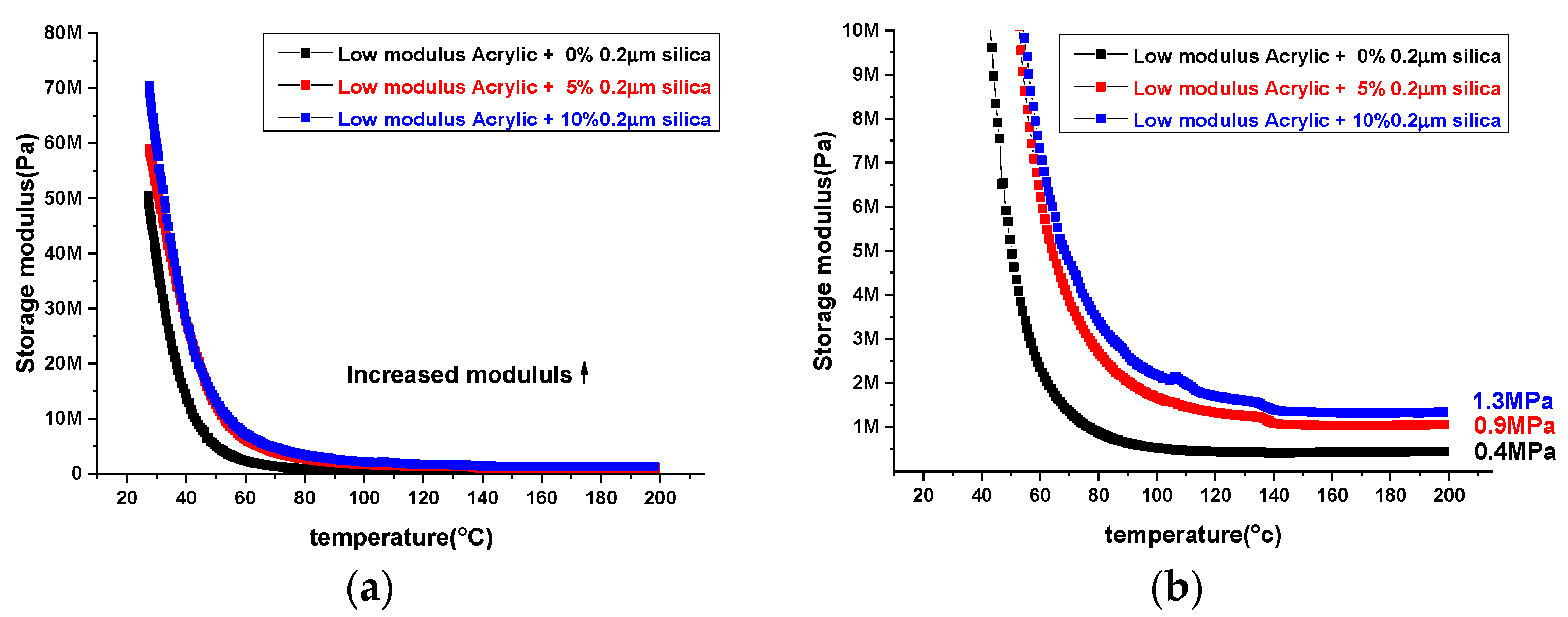
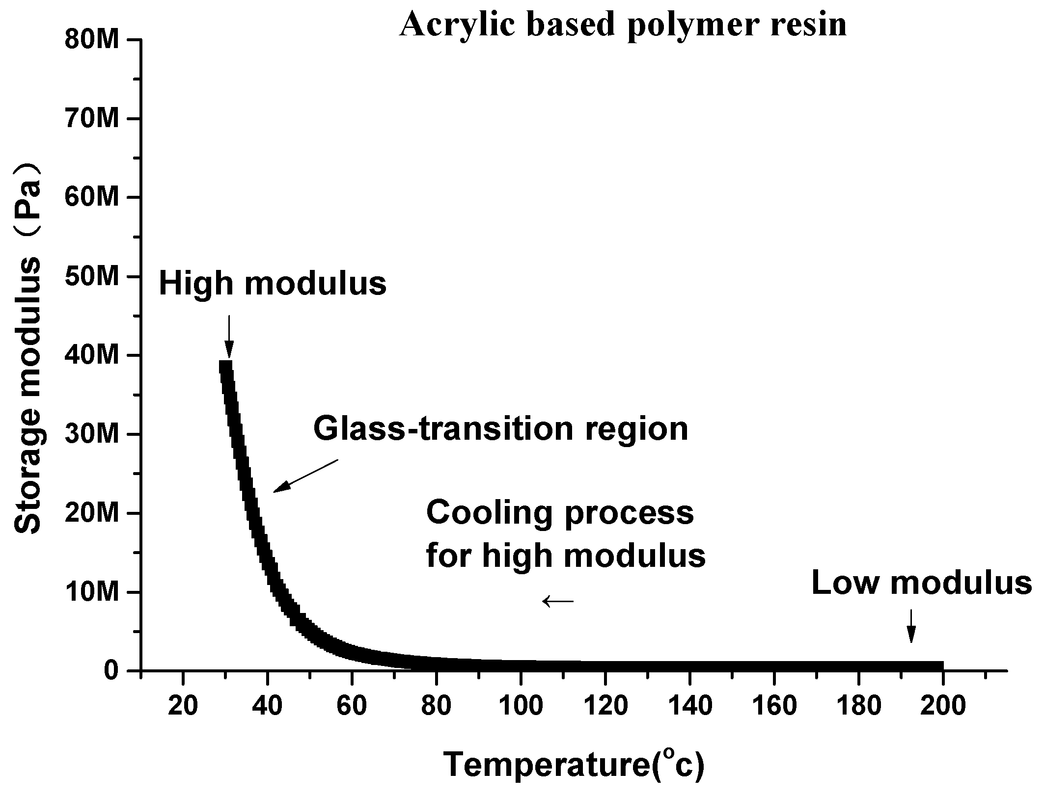
3.4. Effects of Silica Fillers on Increasing Modulus of Acrylic Resin
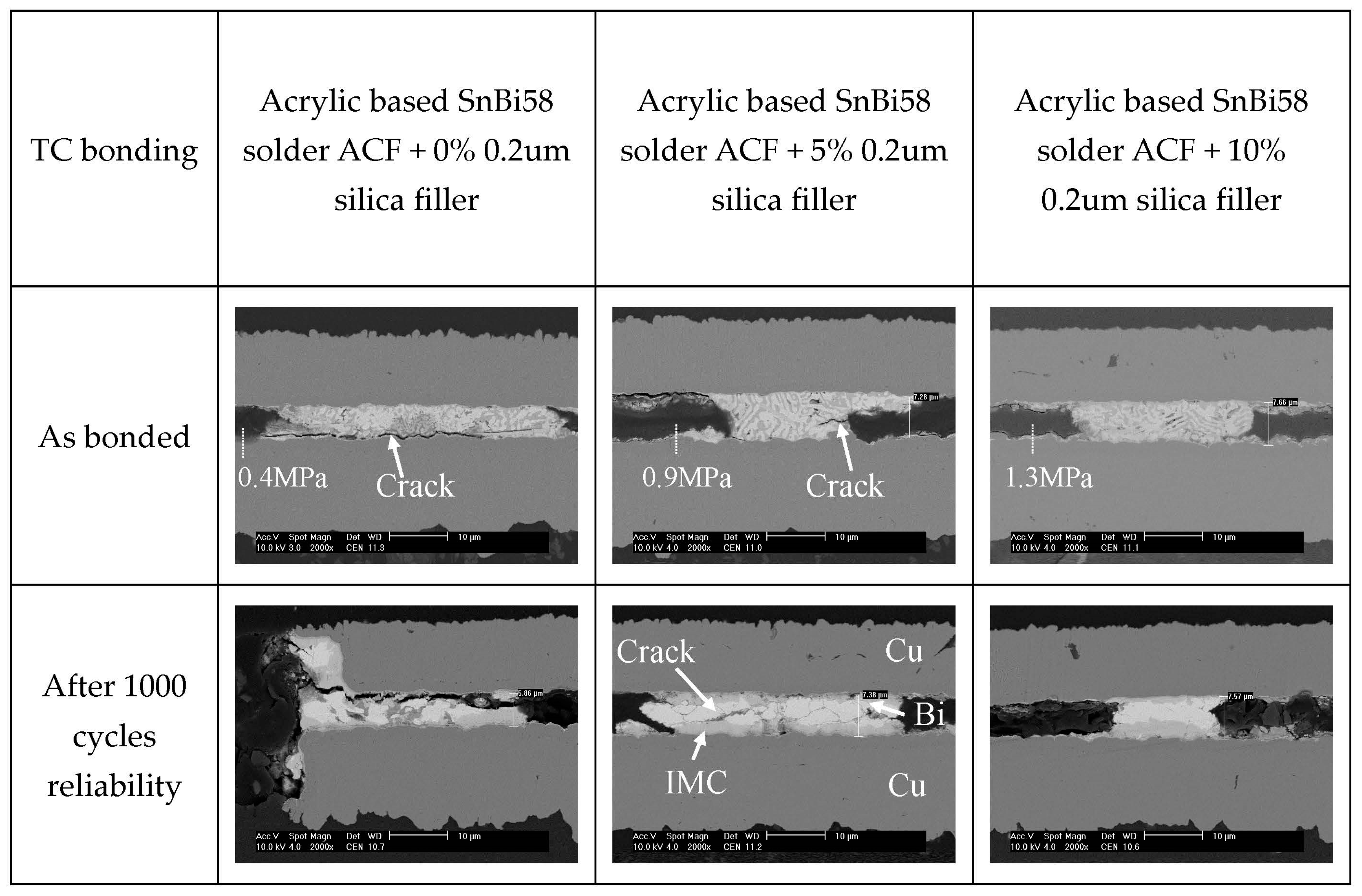
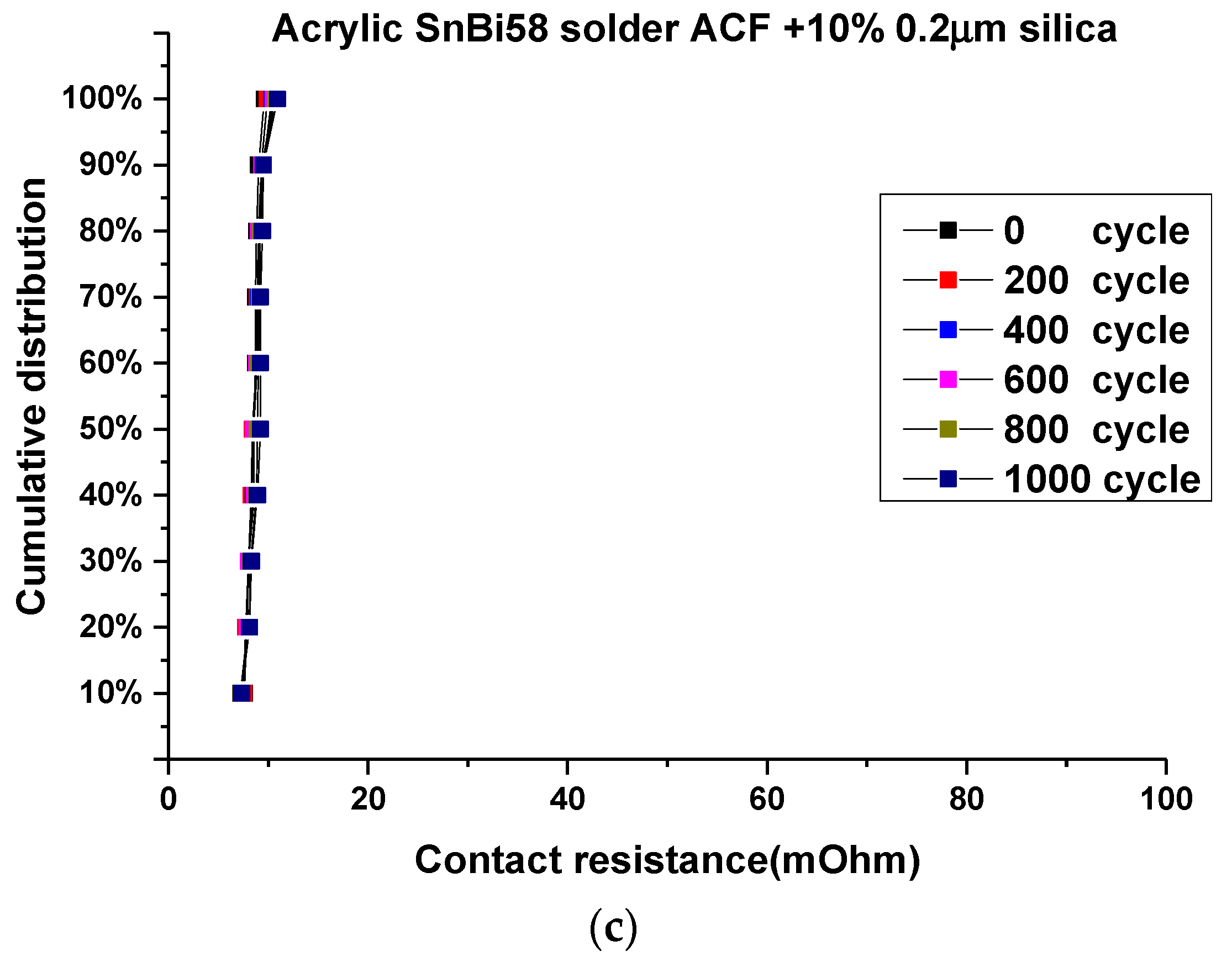
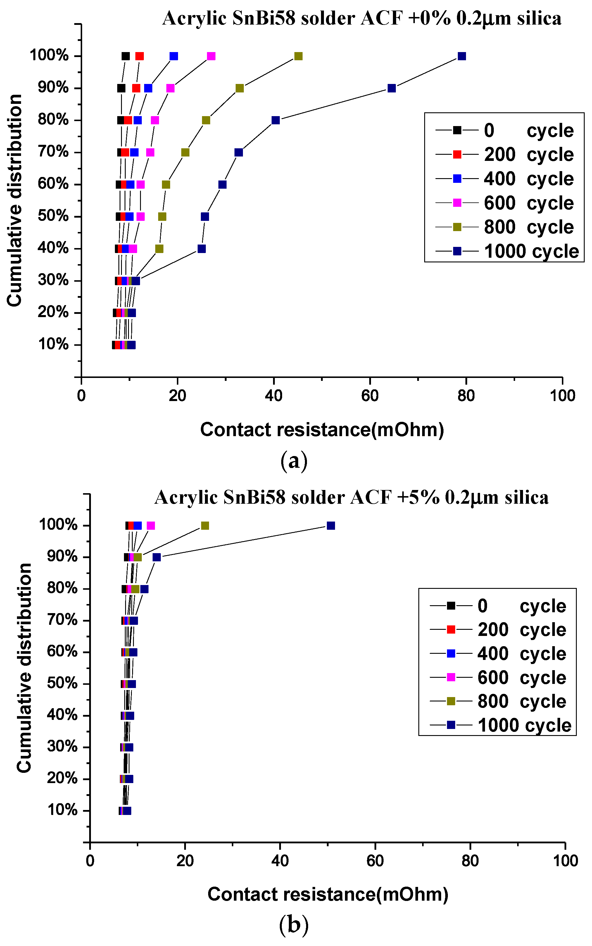
3.5. Reliability Evaluation for Modified Solder ACFs Joint
4. Conclusions
Acknowledgments
Author Contributions
Conflicts of Interest
References
- Singh, P.; Viswanadham, P. Failure Modes and Mechanisms in Electronic Packages; Springer: Berlin, Germany, 2012. [Google Scholar]
- Kiilunen, J.; Frisk, L. Reliability analysis of an ACA attached flex-on-board assembly for industrial application. Solder. Surf. Mt. Technol. 2014, 26, 62–70. [Google Scholar] [CrossRef]
- Lee, K.; Saarinen, I.J.; Pykari, L.; Paik, K.W. High power and high reliability flex-on-board assembly using solder anisotropic conductive films combined with ultrasonic bonding technique. IEEE Trans. Compon. Packag. Manag. Technol. 2011, 1, 1901–1907. [Google Scholar] [CrossRef]
- Zhang, S.; Lin, T.; He, P.; Paik, K.W. Effects of acrylic adhesives property and optimized bonding parameters on Sn 58Bi solder joint morphology for flex-on-board assembly. Microelectron. Reliab. 2017, 78, 181–189. [Google Scholar] [CrossRef]
- Zhang, S.; Kim, S.H.; Kim, T.W.; Kim, Y.S.; Paik, K.W. A study on the solder ball size and content effects of solder ACFs for flex-on-board assembly applications using ultrasonic bonding. IEEE Trans. Compon. Packag. Manag. Technol. 2015, 5, 9–14. [Google Scholar] [CrossRef]
- Kim, S.H.; Choi, Y.; Kim, Y.; Paik, K.W. Flux function added solder anisotropic conductive films (ACFs) for high power and fine pitch assemblies. In Proceedings of the 2013 IEEE 63rd on Electronic Components and Technology Conference (ECTC), Las Vegas, NV, USA, 28–31 May 2013; pp. 1713–1716. [Google Scholar]
- Golla, D.F.; Hughes, P.C. Dynamics of viscoelastic structures—A time-domain, finite element formulation. ASME J. Appl. Mech. 1985, 52, 897–906. [Google Scholar] [CrossRef]
- Zhang, S.; Paik, K.W. Effects of Cooling Processes and Silica Filler Contents of Solder ACFs (Anisotropic Conductive Films) on the Joints Reliability. In Proceedings of the 2016 IEEE 66th on Electronic Components and Technology Conference (ECTC), Las Vegas, NV, USA, 31 May–3 June 2016; pp. 737–742. [Google Scholar]
- Ugural, A.C.; Fenster, S.K. Advanced Strength and Applied Elasticity; Pearson Education: London, UK, 2003. [Google Scholar]
- Graffeuil, J.; Blasquez, G. Caractérisation des matériaux et des composants semiconducteurs au moyen de mesures de bruit de fond. Acta Electron. 1983, 25, 261–279. [Google Scholar]
- Biswas, A.; Manivannan, M.; Srinivasan, M.A. Multiscale layered biomechanical model of the pacinian corpuscle. IEEE Trans. Haptics 2015, 8, 31–42. [Google Scholar] [CrossRef] [PubMed]
- Urayama, K. An experimentalist’s view of the physics of rubber elasticity. J. Polym. Sci. Polym. Phys. 2006, 44, 3440–3444. [Google Scholar] [CrossRef]
- Van Krevelen, D.W.; Nijenhuis, K.T. Properties of Polymers; Their Correlation with Chemical Structure; Their Numerical Estimation and Prediction from Additive Group Contributions; Elsevier: Amsterdam, The Netherlands, 2009. [Google Scholar]
- Vinogradov, G.V.; Yanovsky, Y.G.; Titkova, L.V.; Barancheeva, V.V.; Sergeenkov, S.I.; Borisenkova, E.K. Viscoelastic properties of linear polymers in the fluid state and their transition to the high-elastic state. Polym. Eng. Sci. 1980, 20, 1138–1146. [Google Scholar] [CrossRef]
- Zhang, S.; Paik, K.W. A study on the failure mechanism and enhanced reliability of Sn58Bi solder anisotropic conductive film joints in a pressure cooker test due to polymer viscoelastic properties and hydroswelling. IEEE Trans. Compon. Packag. Manaf. Technol. 2016, 6, 216–223. [Google Scholar] [CrossRef]


| Solder ACFs | Weight Percentage | Calculated Volume Percentage | ||||||
|---|---|---|---|---|---|---|---|---|
| SnBi58 Solder (8.56 g/cm3) | Polymer Resin (1.25 g/cm3) | Ni Particle (8.9 g/cm3) | Silica Filler (2.65 g/cm3) | SnBi58 Solder (8.56 g/cm3) | Polymer Resin (1.25 g/cm3) | Ni Particles (8.9 g/cm3) | Silica Filler (2.65 g/cm3) | |
| ACF 1 | 30% | 1 | 5% | 0% | 6.25% | 92.75% | 1% | 0% |
| ACF 2 | 30% | 1 | 5% | 5% | 6.1% | 89.7% | 0.97% | 3.23% |
| ACF 3 | 30% | 1 | 5% | 10% | 5.9% | 86.9% | 0.93% | 6.27% |
| Dimension Change | Acrylic | Imidazole Epoxy | Cation Epoxy |
|---|---|---|---|
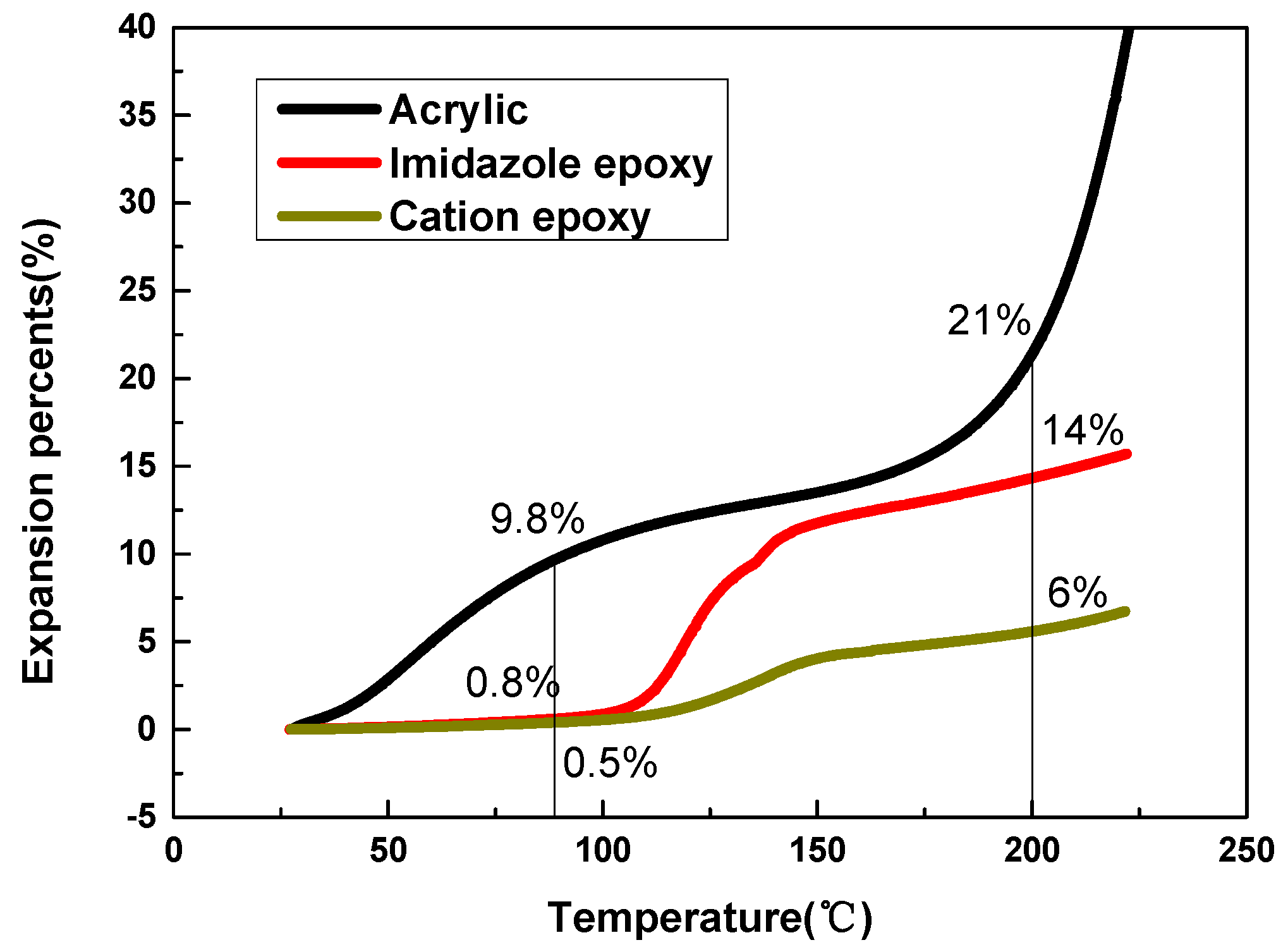
| 200 °C | 21% | 14% | 6% |
| 90 °C | 9.8% | 0.8% | 0.8 |
| 200 cooling to 90 °C | −11.2% | −13.2% | −5.2% |
| Temperature | 200 °C | 150 °C | 100 °C | 50 °C | 30 °C |
|---|---|---|---|---|---|
| Modulus | 0.4 MPa | 0.44 MPa | 0.53 MPa | 5.2 MPa | 34 MPa |
© 2018 by the authors. Licensee MDPI, Basel, Switzerland. This article is an open access article distributed under the terms and conditions of the Creative Commons Attribution (CC BY) license (http://creativecommons.org/licenses/by/4.0/).
Share and Cite
Zhang, S.; Yang, M.; Jin, M.; Huang, W.-C.; Lin, T.; He, P.; Lin, P.; Paik, K.-W. Mechanism of Solder Joint Cracks in Anisotropic Conductive Films Bonding and Solutions: Delaying Hot-Bar Lift-Up Time and Adding Silica Fillers. Metals 2018, 8, 42. https://doi.org/10.3390/met8010042
Zhang S, Yang M, Jin M, Huang W-C, Lin T, He P, Lin P, Paik K-W. Mechanism of Solder Joint Cracks in Anisotropic Conductive Films Bonding and Solutions: Delaying Hot-Bar Lift-Up Time and Adding Silica Fillers. Metals. 2018; 8(1):42. https://doi.org/10.3390/met8010042
Chicago/Turabian StyleZhang, Shuye, Ming Yang, Mingliang Jin, Wen-Can Huang, Tiesong Lin, Peng He, Panpan Lin, and Kyung-Wook Paik. 2018. "Mechanism of Solder Joint Cracks in Anisotropic Conductive Films Bonding and Solutions: Delaying Hot-Bar Lift-Up Time and Adding Silica Fillers" Metals 8, no. 1: 42. https://doi.org/10.3390/met8010042
APA StyleZhang, S., Yang, M., Jin, M., Huang, W.-C., Lin, T., He, P., Lin, P., & Paik, K.-W. (2018). Mechanism of Solder Joint Cracks in Anisotropic Conductive Films Bonding and Solutions: Delaying Hot-Bar Lift-Up Time and Adding Silica Fillers. Metals, 8(1), 42. https://doi.org/10.3390/met8010042