Guidelines for Selecting Plugs Used in Thin-Walled Tube Drawing Processes of Metallic Alloys


Abstract
1. Introduction
2. Methods and Materials
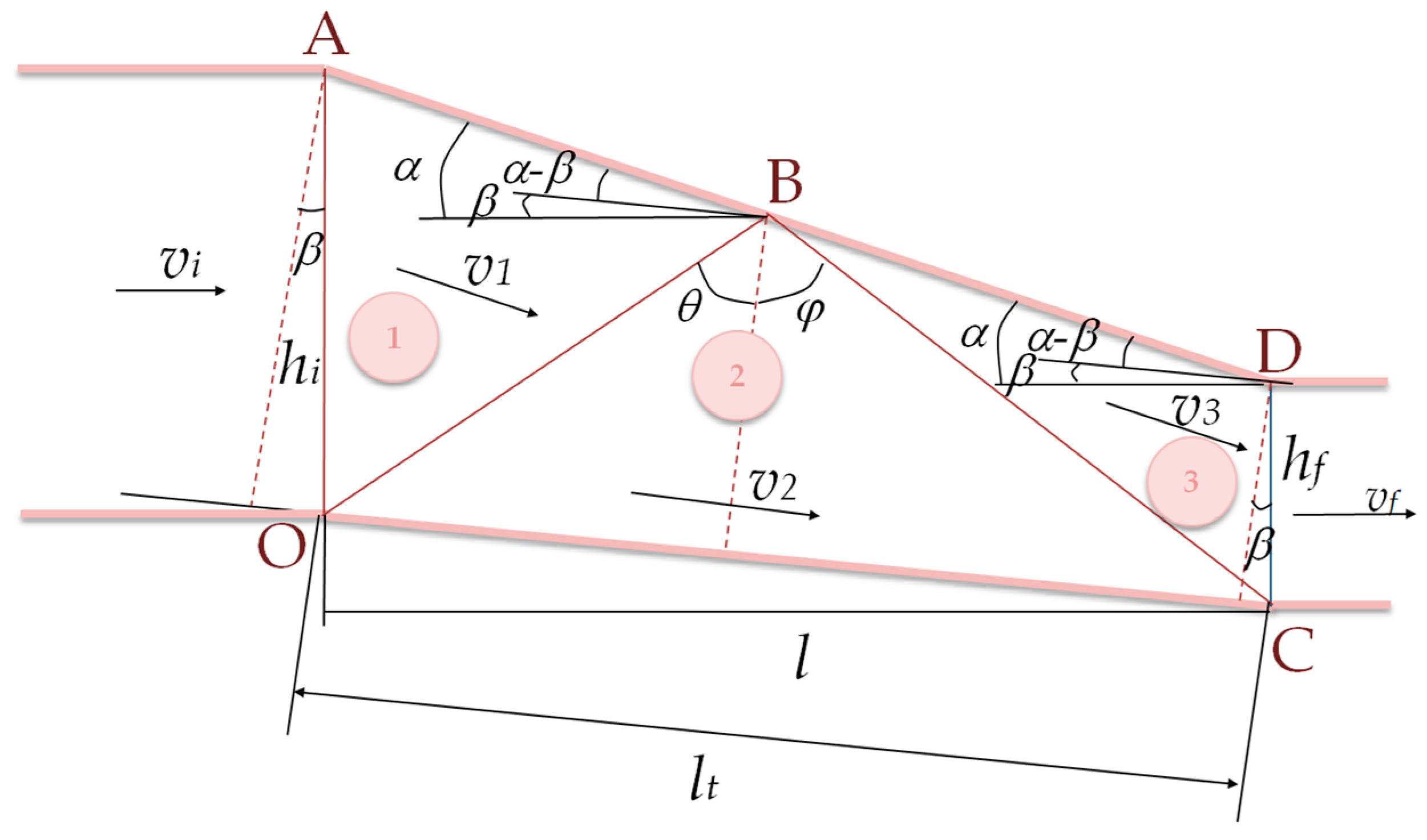
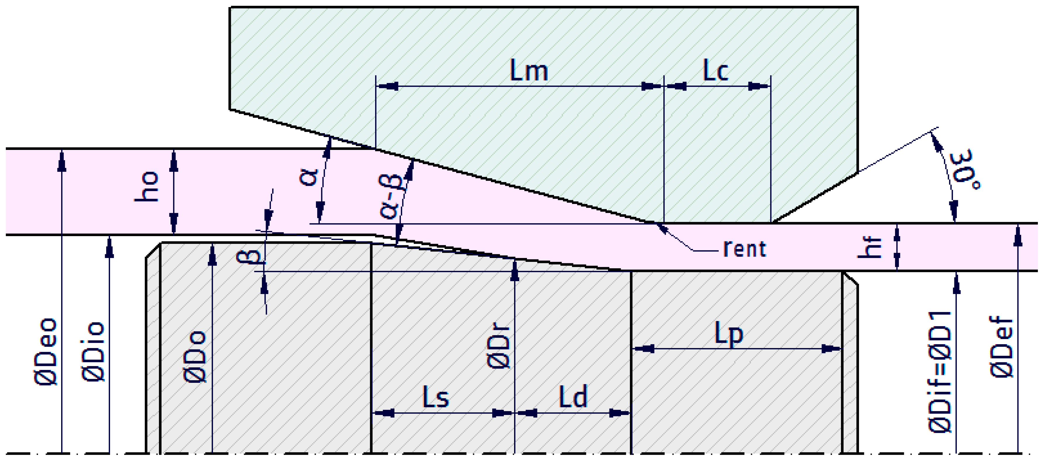
2.1. Analytical Model Based in the Upper Bound Method
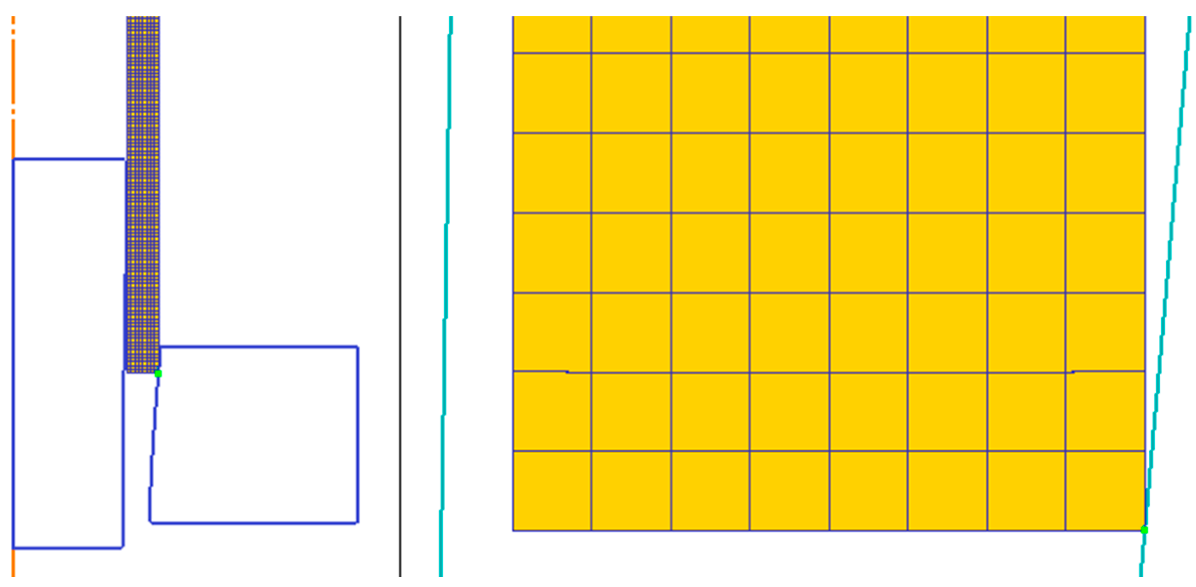
2.2. Numerical Modelling
3. Results and Discussion
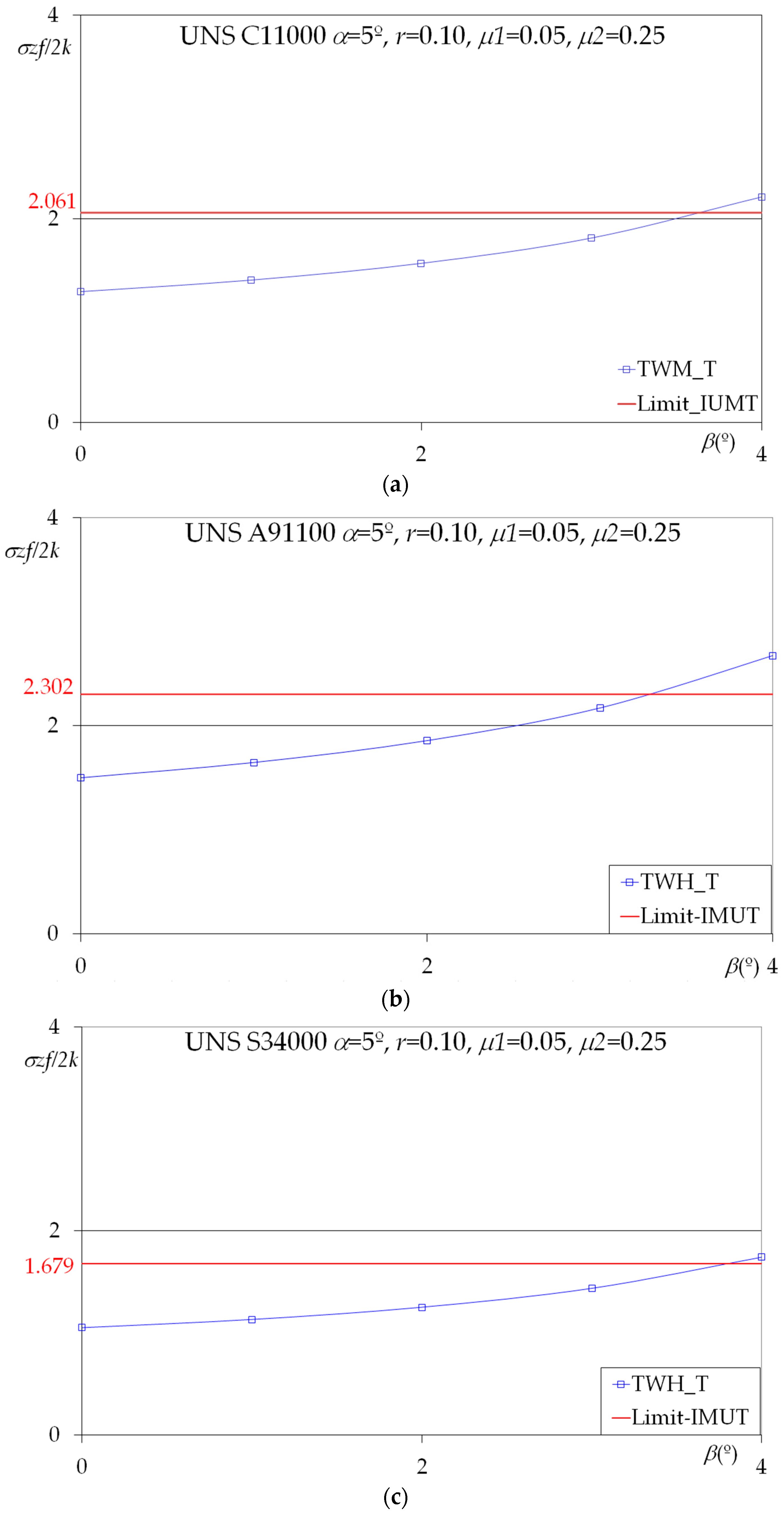
3.1. Theoretical Results
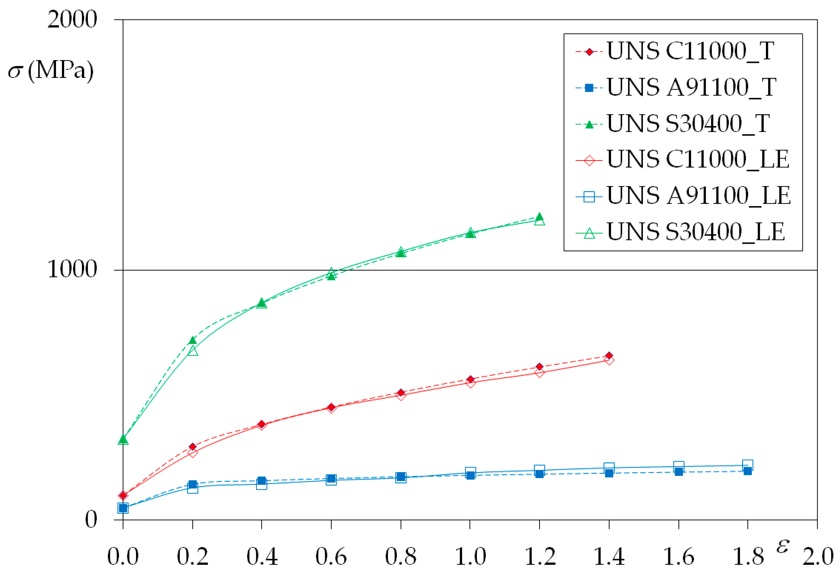
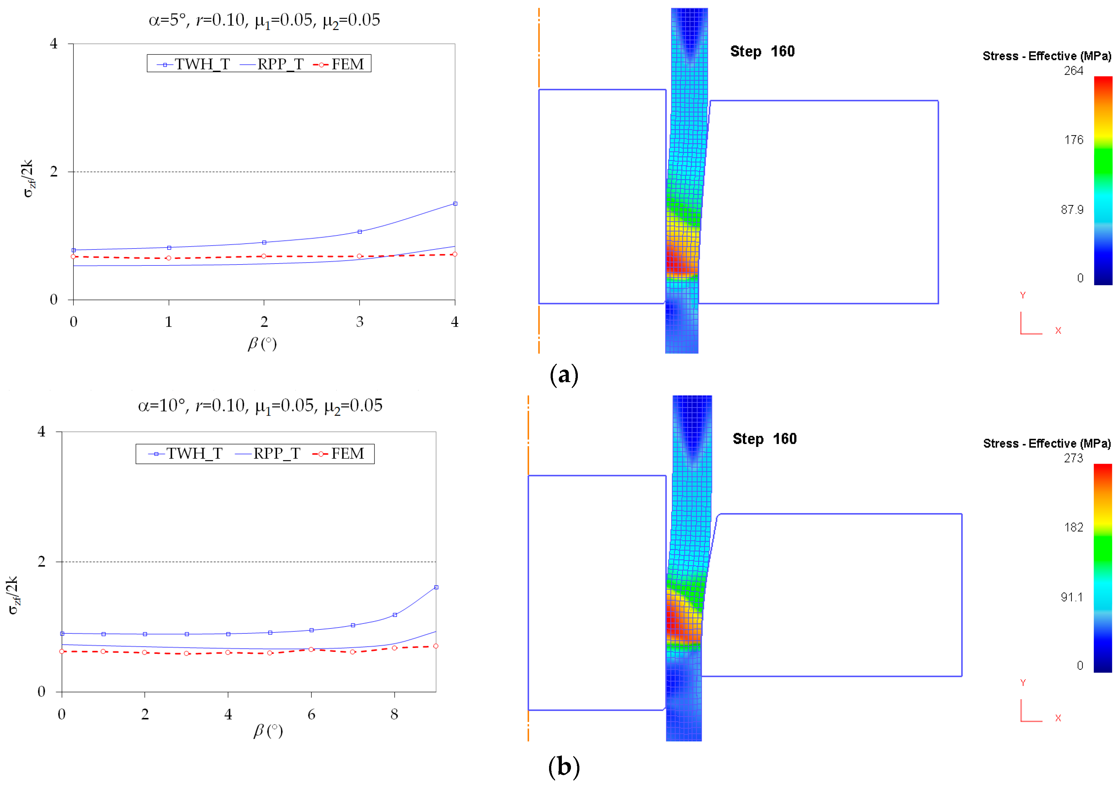
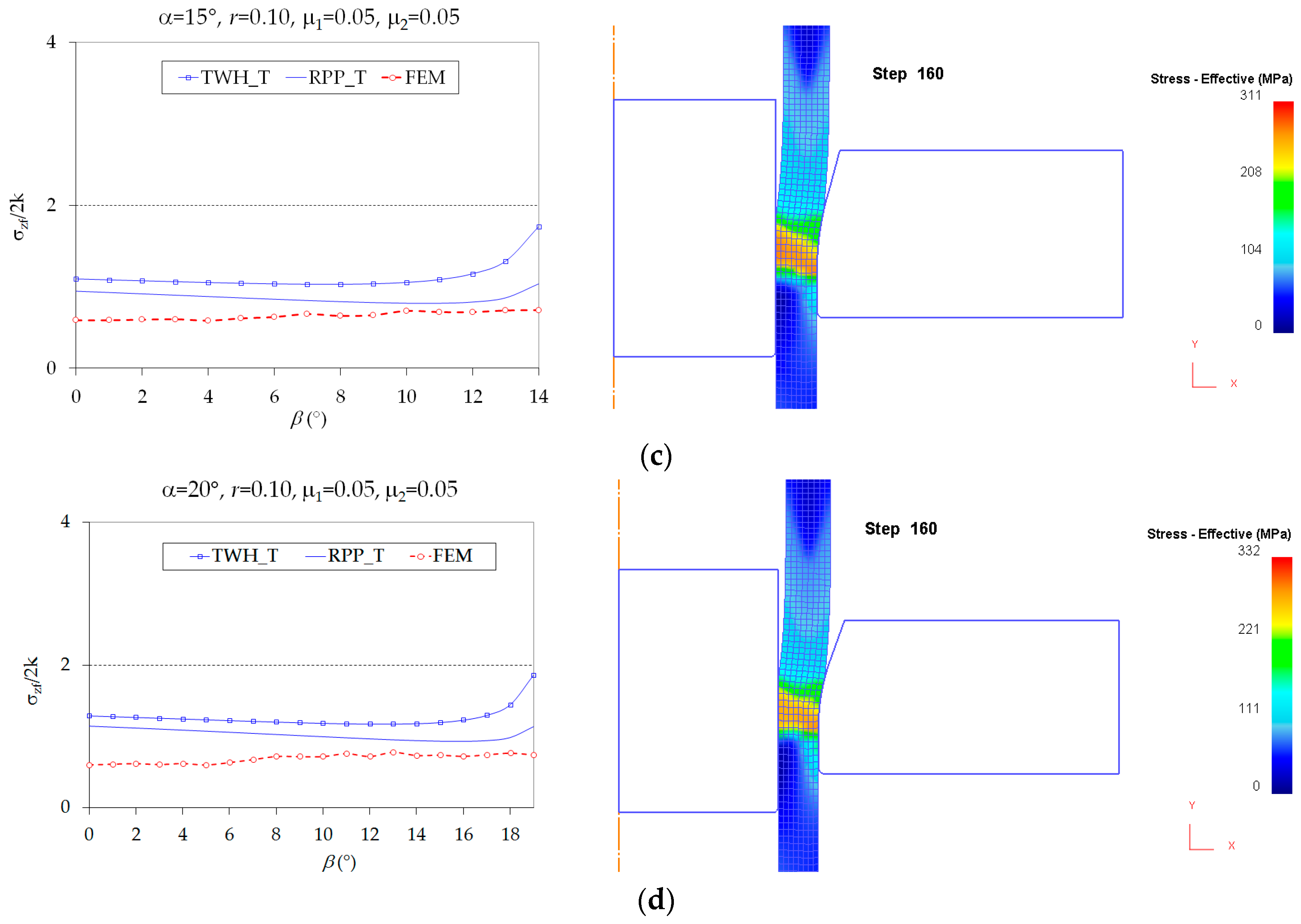
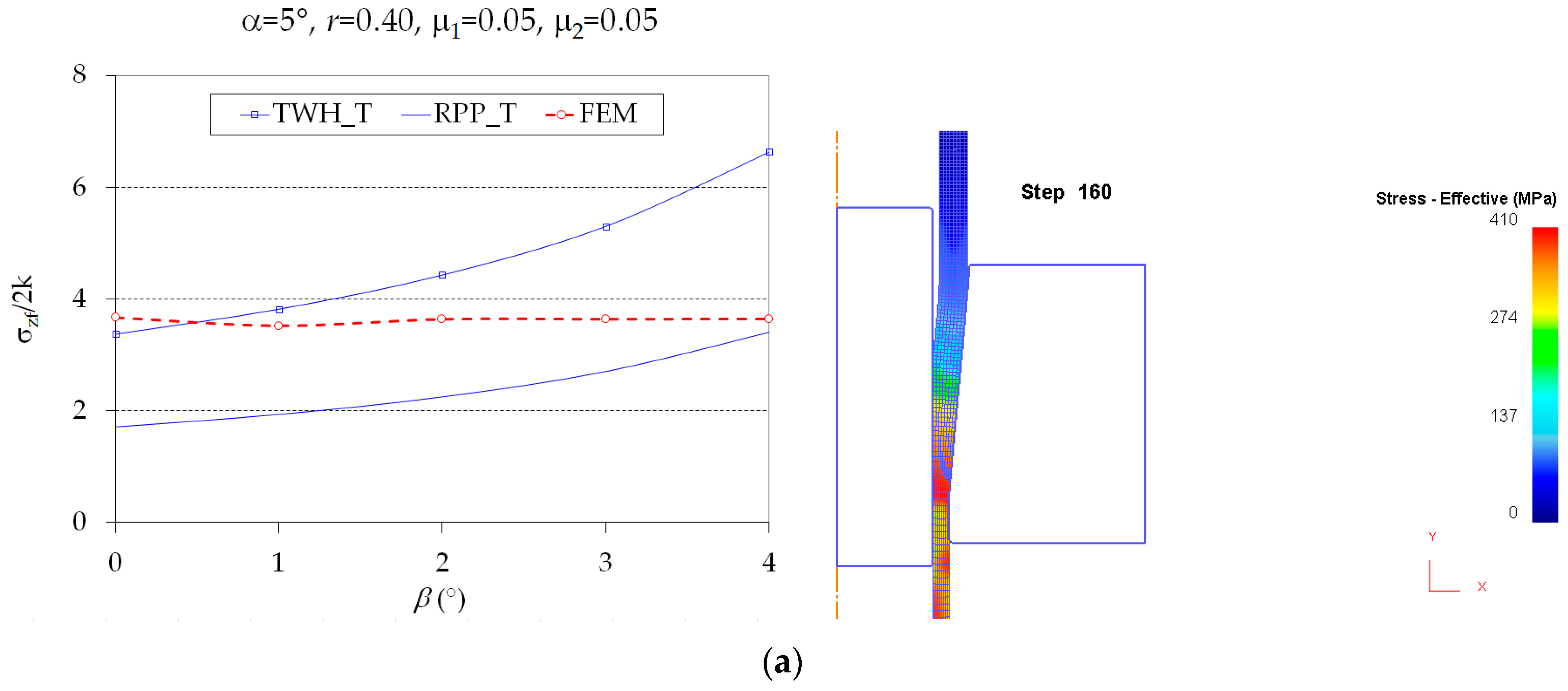
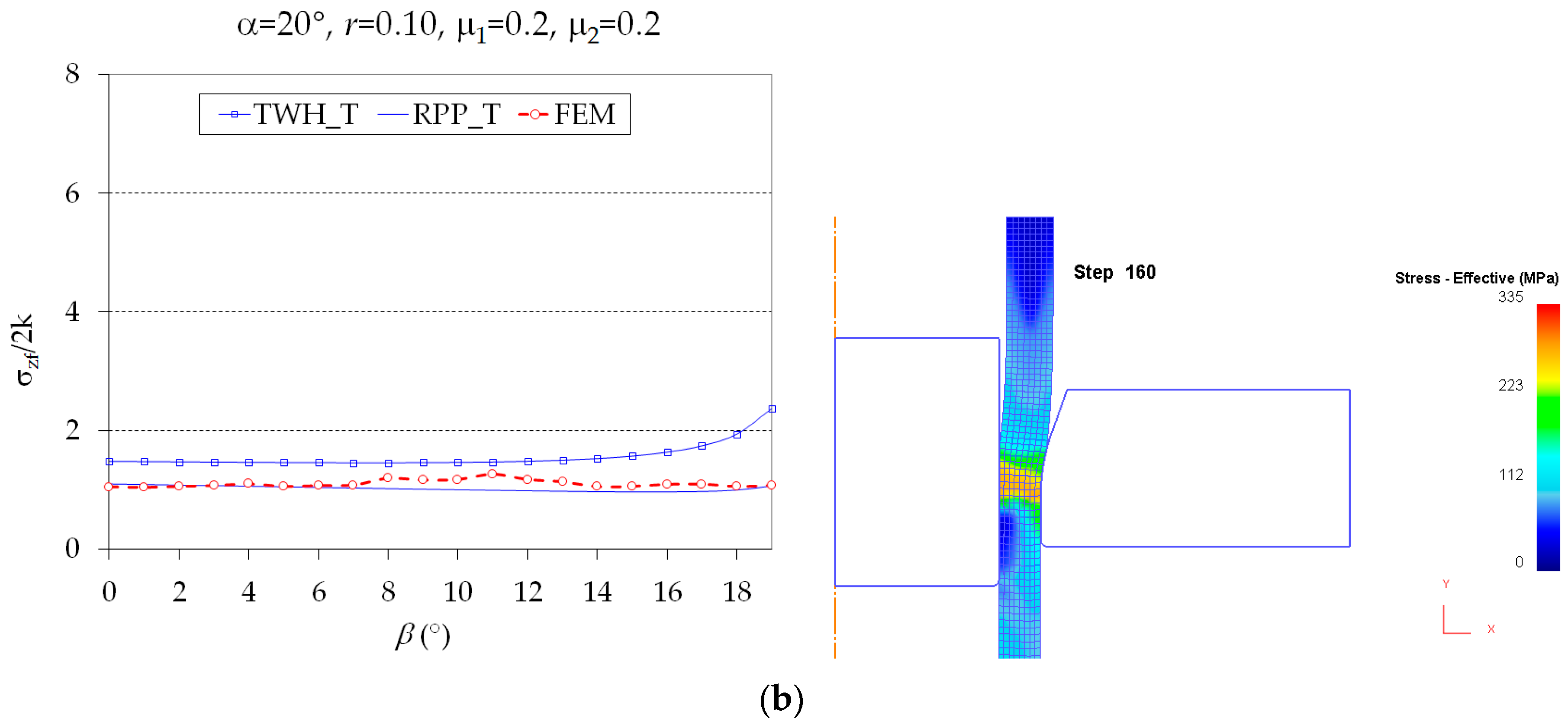
3.2. Analytical Model Validation by Finite Element Analysis
3.3. Analytical Model Validation by Literature Results
4. Conclusions
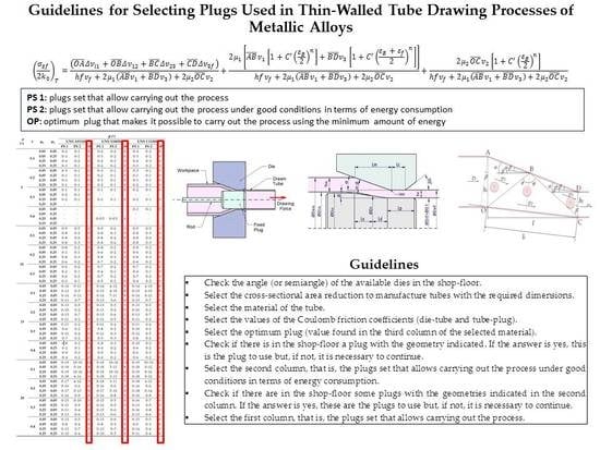
- ▪
- Check the angle (or semiangle) of the available dies in the shop-floor.
- ▪
- Select the cross-sectional area reduction to manufacture tubes with the required dimensions.
- ▪
- Select the material of the tube.
- ▪
- Select the values of the Coulomb friction coefficients (die-tube and tube-plug).
- ▪
- Select the optimum plug (value found in the third column of the selected material).
- ▪
- Check if there is in the shop-floor a plug with the geometry indicated. If the answer is yes, this is the plug to use but, if not, it is necessary to continue.
- ▪
- Select the second column, that is, the plugs set that allows carrying out the process under good conditions in terms of energy consumption.
- ▪
- Check if there are in the shop-floor some plugs with the geometries indicated in the second column. If the answer is yes, these are the plugs to use but, if not, it is necessary to continue.
- ▪
- Select the first column, that is, the plugs set that allows carrying out the process.
Acknowledgments
Author Contributions
Conflicts of Interest
References
- Celentano, D.J.; Palacios, M.A.; Rojas, E.L.; Cruchaga, M.A.; Artigas, A.A.; Monsalve, A.E. Simulation and experimental validation of multiple-step wire drawing processes. Finite Elem. Anal. Des. 2009, 45, 163–180. [Google Scholar] [CrossRef]
- Camacho, A.M.; Domingo, R.; Rubio, E.; González, C. Analysis of the influence of back-pull in drawing process by the finite element method. J. Mater. Process. Technol. 2005, 164–165, 1167–1174. [Google Scholar] [CrossRef]
- Rubio, E.M.; Camacho, A.M.; Sevilla, L.; Sebastián, M.A. Calculation of the forward tension in drawing processes. J. Mater. Process. Technol. 2005, 162–163, 551–557. [Google Scholar] [CrossRef]
- Vega, G.; Haddi, A.; Imad, A. Investigation of process parameters effect on the copper-wire drawing. Mater. Des. 2009, 30, 3308–3312. [Google Scholar] [CrossRef]
- Camacho, A.M.; González, C.; Rubio, E.M.; Sebastián, M.A. Influence of geometrical conditions on central burst appearance in axisymmetrical drawing processes. J. Mater. Process. Technol. 2006, 177, 304–306. [Google Scholar] [CrossRef]
- McAllen, P.J.; Phelan, P. Numerical analysis of axisymmetric wire drawing by means of a coupled damage model. J. Mater. Process. Technol. 2007, 183, 210–218. [Google Scholar] [CrossRef]
- Weygand, S.M.; Riedel, H.; Eberhard, B.; Wouters, G. Numerical simulation of the drawing process of tungsten wires. Int. J. Refract. Met. Hard Mater. 2006, 24, 338–342. [Google Scholar] [CrossRef]
- Haddi, A.; Imad, A.; Vega, G. Analysis of temperature and speed effects on the drawing stress for improving the wire drawing process. Mater. Des. 2011, 32, 4310–4315. [Google Scholar] [CrossRef]
- Lambiase, F.; Di Ilio, A. Deformation inhomogeneity in roll drawing process. J. Manuf. Process. 2012, 14, 208–215. [Google Scholar] [CrossRef]
- Panteghini, A.; Genna, F. Effects of the strain-hardening law in the numerical simulation of wire drawing processes. Comput. Mater. Sci. 2010, 49, 236–242. [Google Scholar] [CrossRef]
- Toribio, J.; Lorenzo, M.; Vergara, D. Hydrogen embrittlement susceptibility of prestressing steel wires: The role of the cold-drawing conditions. Procedia Struct. Integr. 2016, 2, 626–631. [Google Scholar] [CrossRef]
- Toribio, J.; Lorenzo, M.; Vergara, D.; Aguado, L. Residual stress redistribution induced by fatigue in cold-drawn prestressing steel wires. Constr. Build. Mater. 2016, 114, 317–322. [Google Scholar] [CrossRef]
- Toribio, J.; Lorenzo, M.; Vergara, D.; Aguado, L. The role of overloading on the reduction of residual stress by cyclic loading in cold-drawn prestressing steel wires. Appl. Sci. 2017, 7, 84. [Google Scholar] [CrossRef]
- Ripoll, M.R.; Weygand, S.M.; Riedel, H. Reduction of tensile residual stresses during the drawing process of tungsten wires. Mater. Sci. Eng. A 2010, 527, 3064–3072. [Google Scholar] [CrossRef]
- Toribio, J.; Lorenzo, M.; Vergara, D.; Kharin, V. Influence of the die geometry on the hydrogen embrittlement susceptibility of cold drawn wires. Eng. Fail. Anal. 2014, 36, 215–225. [Google Scholar] [CrossRef]
- Baek, H.M.; Jin, Y.G.; Hwang, S.K.; Im, Y.-T.; Son, I.-H.; Lee, D.-L. Numerical study on the evolution of surface defects in wire drawing. J. Mater. Process. Technol. 2012, 212, 776–785. [Google Scholar] [CrossRef]
- Felder, E.; Levrau, C. Analysis of the lubrication by a pseudoplastic fluid: Application to wire drawing. Tribol. Int. 2011, 44, 845–849. [Google Scholar] [CrossRef]
- Bermudo, C.; Sevilla, L.; Martín, F.; Trujillo, F. Study of the tool geometry influence in indentation for the analysis and validation of the new modular upper bound technique. Appl. Sci. 2016, 6, 203. [Google Scholar] [CrossRef]
- Lowrie, J.; Ngaile, G. Analytical modeling of hydrodynamic lubrication in a multiple-reduction drawing die. J. Manuf. Process. 2017, 27, 291–303. [Google Scholar] [CrossRef]
- Lei, X.; Dong, L.; Zhang, Z.; Liu, Y.; Hao, Y.; Yang, R.; Zhang, L.-C. Microstructure, texture evolution and mechanical properties of VT3-1 titanium alloy processed by multi-pass drawing and subsequent isothermal annealing. Metals 2017, 7, 131. [Google Scholar] [CrossRef]
- Juul, K.J.; Nielsen, K.L.; Niordson, C.F. Steady-state numerical modeling of size effects in micron scale wire drawing. J. Manuf. Process. 2017, 25, 163–171. [Google Scholar] [CrossRef]
- Filice, L.; Ambrogio, G.; Guerriero, F. A multi-objective approach for wire-drawing process. Procedia CIRP 2013, 12, 294–299. [Google Scholar] [CrossRef]
- Rubio, E.M. Analytical methods application to the study of tube drawing processes with fixed conical inner plug: Slab and Upper Bound Methods. J. Achiev. Mater. Manuf. Eng. 2006, 14, 119–130. [Google Scholar]
- Rubio, E.M.; Marín, M.; Domingo, R.; Sebastián, M.A. Analysis of plate drawing processes by the upper bound method using theoretical work-hardening materials. Int. J. Adv. Manuf. Technol. 2009, 40, 261–269. [Google Scholar] [CrossRef]
- Avitzur, B. Handbook of Metal Forming Processes; John Wiley & Sons: New York, NY, USA, 1983; ISBN 978-0471034742. [Google Scholar]
- Hill, R. The Mathematical Theory of Plasticity; Oxford University Press: London, UK, 1950. [Google Scholar]
- Rowe, G.W. Elements of Metalworking Theory; Edward Arnold: London, UK, 1979. [Google Scholar]
- Hoffman, O.; Sachs, G. Introduction to the Theory of Plasticity for Engineers; McGraw-Hill Book Company Inc.: New York, NY, USA, 1953. [Google Scholar]
- Slater, R.A.C. Engineering Plasticity: Theory and Application to Metal Forming Processes; The Macmillan Press Ltd.: London, UK, 1977; ISBN 9780333157091. [Google Scholar]
- Yoshida, K.; Watanabe, M.; Ishikawa, H. Drawing of Ni-Ti shape-memory-alloy fine tubes used in medical tests. J. Mater. Process. Technol. 2001, 118, 251–255. [Google Scholar] [CrossRef]
- Yoshida, K.; Furuya, H. Mandrel drawing and plug drawing of shape-memory-alloy fine tubes used in catheters and stents. J. Mater. Process. Technol. 2004, 153–154, 145–150. [Google Scholar] [CrossRef]
- Avitzur, B. Metal Forming: The Application of Limit Analysis; Marcel Dekker: New York, NY, USA, 1980. [Google Scholar]
- Talbert, S.H.; Avitzur, B. Element Mechanics of Plastic Flow in Metal Forming; John Wiley & Sons: New York, NY, USA, 1996; ISBN 9780471960034. [Google Scholar]
- Rubio, E.M.; Camacho, A.M.; Pérez, R.; Marín, M. Modelo mejorado de bloques rígidos triangulares para el análisis mediante el método del límite superior de procesos de estirado de tubos con tapón interior cónico fijo. In Actas del XXII Congreso Nacional de Ingeniería Mecánica; Asociación Española de Ingeniería Mecánica: Madrid, Spain, 2018. [Google Scholar]
- Kuhn, H.; Medlin, D. ASM Handbook Volume 8: Mechanical Testing and Evaluation; ASM International Metals Parks: Materials Park, OH, USA, 2000; ISBN 9780871703897. [Google Scholar]
- Hollomon, J.H.; Jaffe, L.D. Time-temperature relations in tempering steel. Trans. Am. Inst. Min. Metall. Eng. 1945, 162, 223–249. [Google Scholar]
- Rao, K.P.; Doraivelu, S.M.; Gopinathan, V. Flow curves and deformation of materials at different temperatures and strain rates. J. Mech. Work. Technol. 1982, 6, 63–88. [Google Scholar] [CrossRef]
- Hosford, W.F.; Caddell, R.M. Metal Forming: Mechanics and Metallurgy; Cambridge University Press: New York, NY, USA, 2007; ISBN 9780521881210. [Google Scholar]
- Johnson, W.; Mellor, P.B. Engineering Plasticity; Ellis Horwood: Chichester, UK, 1983. [Google Scholar]
- Roylance, D. Stress-Stain Curves; Department of Materials Science and Engineering, Massachusets Institute of Tecnology: Cambrige, MA, USA, 2001. [Google Scholar]
- Kalpakjian, S.; Schmid, S.R. Manufacturing Processes for Engineering Materials, 5th ed.; Prentice-Hall/Pearson Education: Upper Saddle River, NJ, USA, 2008. [Google Scholar]
- Corporation, S.F.T. DEFORM-F2 v11.0 User’s Manual; Scientific Forming Technologies Corporation: Columbus, OH, USA, 2014. [Google Scholar]
- Amigo, F.J.; Camacho, A.M. Reduction of induced central damage in cold extrusion of dual-phase steel DP800 using double-pass dies. Metals 2017, 7, 335. [Google Scholar] [CrossRef]
- Centeno, G.; Martínez-Donaire, A.; Bagudanch, I.; Morales-Palma, D.; Garcia-Romeu, M.; Vallellano, C. Revisiting formability and failure of AISI304 sheets in spif: Experimental approach and numerical validation. Metals 2017, 7, 531. [Google Scholar] [CrossRef]
- Neves, F.O.; Button, S.T.; Caminaga, C.; Gentile, F.C. Numerical and experimental analysis of tube drawing with fixed plug. J. Braz. Soc. Mech. Sci. Eng. 2005, 27, 426–431. [Google Scholar] [CrossRef]
- Danckert, J.; Endelt, B. LS-DYNA® used to analyze the drawing of precision tubes. In Proceedings of the 7th European LS-DYNA Conference, Salzburg, Germany, 14–15 May 2009. [Google Scholar]
- Świątkowski, K.; Hatalak, R. Application of modified tools in the process of thin-walled tube drawing. Arch. Metall. Mater. 2006, 51, 193–197. [Google Scholar]
- Palengat, M.; Chagnon, G.; Favier, D.; Louche, H.; Linardon, C.; Plaideau, C. Cold drawing of 316L stainless steel thin-walled tubes: Experiments and finite element analysis. Int. J. Mech. Sci. 2013, 70, 69–78. [Google Scholar] [CrossRef]
- Martín, F.; Camacho, A.M.; Domingo, R.; Sevilla, L. Modular procedure to improve the application of the upper-bound theorem in forging. Mater. Manuf. Process. 2013, 28, 282–286. [Google Scholar] [CrossRef]
- Camacho, A.M.; Rubio, E.M.; González, C.; Sebastián, M.A. Study of drawing processes by analytical and finite element methods. Mater. Sci. Forum 2006, 526, 187–192. [Google Scholar] [CrossRef]


| Parameters | Materials | ||
|---|---|---|---|
| UNS C11000 | UNS A91100 | UNS S34000 | |
| (MPa) | 100 | 50 | 320 |
| (MPa) | 315 | 180 | 1275 |
| 0.54 | 0.20 | 0.45 | |
| 1.5 | −1.0 | −1.4 | |
| (°) | (°) | |||
|---|---|---|---|---|
| 5 | 1–4 | 0.10–0.40 | 0–0.25 | 0–0.25 |
| 10 | 1–9 | |||
| 15 | 1–14 | |||
| 20 | 1–19 |
| 22.00 | 20.76 | 17.32 | 16.55 | 2.34 | 2.11 |
| (°) | (°) | |||||||||||
|---|---|---|---|---|---|---|---|---|---|---|---|---|
| UNS A91100 | UNS S34000 | UNS C11000 | ||||||||||
| PS 1 | PS 2 | OP | PS 1 | PS 2 | OP | PS 1 | PS 2 | OP | ||||
| 5 | 0.1 | 0.05 | 0.05 | 0–4 | 0–1 | 0 | 0–4 | 0–2 | 0 | 0–4 | 0–2 | 0 |
| 0.05 | 0.25 | 0–3 | 0–1 | 0 | 0–3 | 0–2 | 0 | 0–3 | 0–2 | 0 | ||
| 0.25 | 0.05 | 0–4 | 0–2 | 0 | 0–4 | 0–3 | 0 | 0–4 | 0–3 | 0 | ||
| 0.25 | 0.25 | 0–3 | 0–1 | 0 | 0–4 | 0–2 | 0 | 0–3 | 0–2 | 0 | ||
| 0.2 | 0.05 | 0.05 | 0–3 | 0–1 | 0 | 0–3 | 0–1 | 0 | 0–3 | 0–1 | 0 | |
| 0.05 | 0.25 | 0–1 | 0–1 | 0 | 0–2 | 0–1 | 0 | 0–1 | 0–1 | 0 | ||
| 0.25 | 0.05 | 0–3 | 0–1 | 0 | 0–3 | 0–1 | 0 | 0–3 | 0–1 | 0 | ||
| 0.25 | 0.25 | 0–1 | 0–1 | 0 | 0–2 | 0–1 | 0 | 0–2 | 0–1 | 0 | ||
| 0.3 | 0.05 | 0.05 | 0–1 | 0–1 | 0 | 0–1 | 0–1 | 0 | 0–2 | 0–1 | 0 | |
| 0.05 | 0.25 | 0–2 | 0–1 | 0 | - | - | - | - | - | - | ||
| 0.25 | 0.05 | 0–2 | 0–1 | 0 | 0–2 | 0–1 | 0 | 0–2 | 0–1 | 0 | ||
| 0.25 | 0.25 | - | - | - | - | - | - | - | - | - | ||
| 0.4 | 0.05 | 0.05 | - | - | - | - | - | - | 0–1 | 0–1 | 0 | |
| 0.05 | 0.25 | - | - | - | - | - | - | - | - | - | ||
| 0.25 | 0.05 | - | - | - | 0–0.5 | 0–0.5 | 0 | - | - | - | ||
| 0.25 | 0.25 | - | - | - | - | - | - | - | - | - | ||
| 10 | 0.1 | 0.05 | 0.05 | 0–9 | 0–5 | 2 | 0–9 | 0–6 | 3 | 0–9 | 0–5 | 3 |
| 0.05 | 0.25 | 0–8 | 0–2 | 0 | 0–8 | 0–3 | 0 | 0–8 | 0–3 | 0 | ||
| 0.25 | 0.05 | 0–8 | 0–6 | 2 | 0–8 | 0–4 | 0 | 0–8 | 0–6 | 3 | ||
| 0.25 | 0.25 | 0–8 | 0–3 | 0 | 0–8 | 0–4 | 0 | 0–8 | 0–3 | 0 | ||
| 0.2 | 0.05 | 0.05 | 0–8 | 0–2 | 0 | 0–8 | 0–2 | 0 | 0–8 | 0–2 | 0 | |
| 0.05 | 0.25 | 0–1 | 0–1 | 0 | 0–6 | 0–2 | 0 | 0–6 | 0–2 | 0 | ||
| 0.25 | 0.05 | 0–8 | 0–3 | 0 | 0–8 | 0–3 | 0 | 0–8 | 0–3 | 0 | ||
| 0.25 | 0.25 | 0–6 | 0–2 | 0 | 0–7 | 0–2 | 0 | 0–6 | 0–2 | 0 | ||
| 0.3 | 0.05 | 0.05 | 0–6 | 0–2 | 0 | 0–7 | 0–2 | 0 | 0–7 | 0–2 | 0 | |
| 0.05 | 0.25 | 0–2 | 0–1 | 0 | 0–4 | 0–1 | 0 | 0–4 | 0–1 | 0 | ||
| 0.25 | 0.05 | 0–6 | 0–2 | 0 | 0–7 | 0–2 | 0 | 0–7 | 0–2 | 0 | ||
| 0.25 | 0.25 | 0–3 | 0–1 | 0 | 0–5 | 0–2 | 0 | 0–4 | 0–2 | 0 | ||
| 0.4 | 0.05 | 0.05 | 0–8 | 0–3 | 0 | 0–4 | 0–2 | 0 | 0–5 | 0–2 | 0 | |
| 0.05 | 0.25 | - | - | - | - | - | - | 0–1 | 0–1 | 0 | ||
| 0.25 | 0.05 | 0–4 | 0–2 | 0 | 0–5 | 0–2 | 0 | 0–5 | 0–2 | 0 | ||
| 0.25 | 0.25 | - | - | - | 0–2 | 0–1 | 0 | 0–2 | 0–1 | 0 | ||
| 15 | 0.1 | 0.05 | 0.05 | 0–14 | 0–11 | 7 | 0–14 | 4–12 | 8 | 0–14 | 4–10 | 8 |
| 0.05 | 0.25 | 0–13 | 0–5 | 0 | 0–13 | 4–10 | 8 | 0–13 | 4–10 | 8 | ||
| 0.25 | 0.05 | 0–14 | 0–11 | 7 | 0–14 | 7–11 | 9 | 0–14 | 0–11 | 7 | ||
| 0.25 | 0.25 | 0–13 | 0–7 | 0 | 0–13 | 3–6 | 4 | 0–13 | 0–7 | 0 | ||
| 0.2 | 0.05 | 0.05 | 0–13 | 0–5 | 0 | 0–13 | 0–5 | 3 | 0–13 | 0–5 | 0 | |
| 0.05 | 0.25 | 0–10 | 0–2 | 0 | 0–11 | 0–4 | 0 | 0–10 | 0–2 | 0 | ||
| 0.25 | 0.05 | 0–13 | 0–7 | 0 | 0–13 | 0–6 | 2 | 0–13 | 0–7 | 0 | ||
| 0.25 | 0.25 | 0–11 | 0–2 | 0 | 0–11 | 0–5 | 0 | 0–11 | 0–2 | 0 | ||
| 0.3 | 0.05 | 0.05 | 0–11 | 0–2 | 0 | 0–11 | 0–4 | 0 | 0–11 | 0–4 | 0 | |
| 0.05 | 0.25 | 0–6 | 0–2 | 0 | 0–8 | 0–2 | 0 | 0–10 | 0–2 | 0 | ||
| 0.25 | 0.05 | 0–11 | 0–4 | 0 | 0–11 | 0–3 | 0 | 0–12 | 0–5 | 0 | ||
| 0.25 | 0.25 | 0–7 | 0–2 | 0 | 0–9 | 0–3 | 0 | 0–8 | 0–4 | 0 | ||
| 0.4 | 0.05 | 0.05 | 0–8 | 0–2 | 0 | 0–8 | 0–3 | 0 | 0–10 | 0–2 | 0 | |
| 0.05 | 0.25 | 0–2 | 0–1 | 0 | 0–4 | 0–2 | 0 | 0–6 | 0–2 | 0 | ||
| 0.25 | 0.05 | 0–9 | 0–3 | 0 | 0–9 | 0–3 | 0 | 0–6 | 0–3 | 0 | ||
| 0.25 | 0.25 | 0–4 | 0–2 | 0 | 0–6 | 0–2 | 0 | 0–6 | 0–2 | 0 | ||
| 20 | 0.1 | 0.05 | 0.05 | 0–19 | 10–16 | 14 | 0–19 | 10–16 | 13 | 0–19 | 10–16 | 12 |
| 0.05 | 0.25 | 0–18 | 0–16 | 8 | 0–18 | 5–11 | 8 | 0–18 | 0–12 | 4 | ||
| 0.25 | 0.05 | 0–19 | 10–16 | 14 | 0–19 | 10–16 | 12 | 0–19 | 8–16 | 12 | ||
| 0.25 | 0.25 | 0–18 | 6–14 | 9 | 0–18 | 3–13 | 9 | 0–18 | 0–12 | 6 | ||
| 0.2 | 0.05 | 0.05 | 0–17 | 4–12 | 9 | 0–18 | 3–11 | 7 | 0–18 | 4–11 | 6 | |
| 0.05 | 0.25 | 0–16 | 0–6 | 0 | 0–16 | 0–6 | 0 | 0–16 | 0–6 | 0 | ||
| 0.25 | 0.05 | 0–17 | 0–13 | 8 | 0–17 | 5–10 | 8 | 0–18 | 0–14 | 6 | ||
| 0.25 | 0.25 | 0–16 | 0–9 | 0 | 0–16 | 0–8 | 0 | 0–16 | 0–8 | 0 | ||
| 0.3 | 0.05 | 0.05 | 0–15 | 0–10 | 0 | 0–15 | 0–5 | 0 | 0–16 | 0–7 | 0 | |
| 0.05 | 0.25 | 0–15 | 0–9 | 0 | 0–12 | 0–5 | 0 | 0–13 | 0–5 | 0 | ||
| 0.25 | 0.05 | 0–11 | 0–4 | 0 | 0–15 | 0–6 | 1 | 0–16 | 0–8 | 0 | ||
| 0.25 | 0.25 | 0–13 | 0–6 | 0 | 0–13 | 0–6 | 0 | 0–13 | 0–6 | 0 | ||
| 0.4 | 0.05 | 0.05 | 0–13 | 0–5 | 0 | 0–13 | 0–6 | 0 | 0–15 | 0–5 | 0 | |
| 0.05 | 0.25 | 0–8 | 0–4 | 0 | 0–8 | 0–3 | 0 | 0–9 | 0–3 | 0 | ||
| 0.25 | 0.05 | 0–13 | 0–7 | 0 | 0–13 | 0–5 | 0 | 0–14 | 0–6 | 0 | ||
| 0.25 | 0.25 | 0–10 | 0–4 | 0 | 0–10 | 0–5 | 0 | 0–11 | 0–4 | 0 | ||
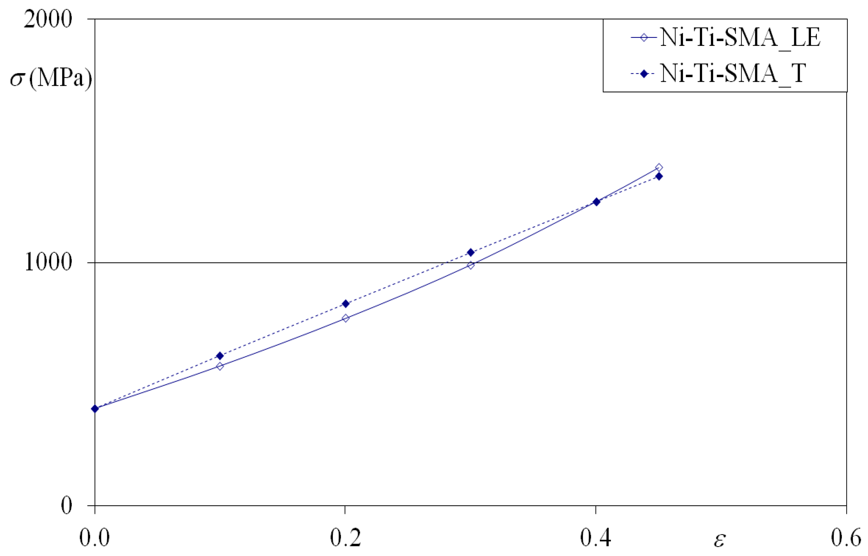
| Parameters | Material |
|---|---|
| Ni–Ti-SMA_T | |
| (MPa) | 400 |
| (MPa) | 1750 |
| 0.95 | |
| 1.85 |
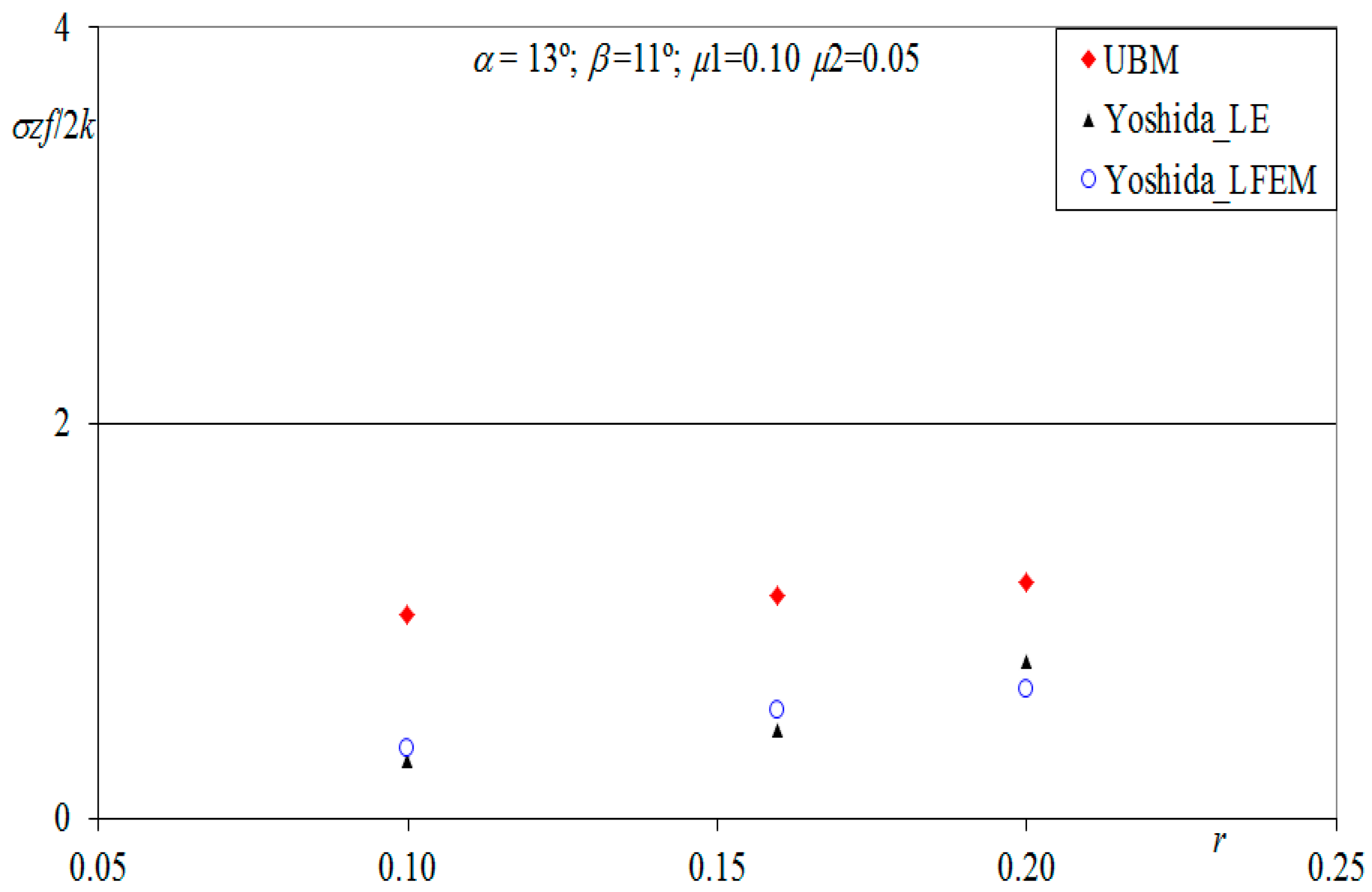
| α = 13°; β = 11°; μ1 = 0.10; μ2 = 0.05 | |||
|---|---|---|---|
| r | σzf/2 k LFEM | σzf/2 k LE | σzf/2 k UBM |
| 0.10 | 0.350 | 0.300 | 1.035 |
| 0.16 | 0.550 | 0.450 | 1.130 |
| 0.20 | 0.650 | 0.800 | 1.192 |
© 2017 by the authors. Licensee MDPI, Basel, Switzerland. This article is an open access article distributed under the terms and conditions of the Creative Commons Attribution (CC BY) license (http://creativecommons.org/licenses/by/4.0/).
Share and Cite
Rubio, E.M.; Camacho, A.M.; Pérez, R.; Marín, M.M. Guidelines for Selecting Plugs Used in Thin-Walled Tube Drawing Processes of Metallic Alloys. Metals 2017, 7, 572. https://doi.org/10.3390/met7120572
Rubio EM, Camacho AM, Pérez R, Marín MM. Guidelines for Selecting Plugs Used in Thin-Walled Tube Drawing Processes of Metallic Alloys. Metals. 2017; 7(12):572. https://doi.org/10.3390/met7120572
Chicago/Turabian StyleRubio, Eva María, Ana María Camacho, Raúl Pérez, and Marta María Marín. 2017. "Guidelines for Selecting Plugs Used in Thin-Walled Tube Drawing Processes of Metallic Alloys" Metals 7, no. 12: 572. https://doi.org/10.3390/met7120572
APA StyleRubio, E. M., Camacho, A. M., Pérez, R., & Marín, M. M. (2017). Guidelines for Selecting Plugs Used in Thin-Walled Tube Drawing Processes of Metallic Alloys. Metals, 7(12), 572. https://doi.org/10.3390/met7120572