Article

Investigation on Ti0.94Zr0.08Cr1.0Mn0.6−xFe0.4+x (x = 0, 0.1, 0.2, 0.3, 0.4) Alloys for 25 MPa Hydrogen Compression Materials

1
Institute of Modern Physics, Fudan University, Shanghai 200433, China
2
Inner Mongolia Rare Earth Ovonic Metal Hydride Co., Ltd., Baotou 014010, China
3
School of Rare Earth Industry, Inner Mongolia University of Science and Technology, Baotou 014010, China
*
Authors to whom correspondence should be addressed.
Metals 2026, 16(9), 965; https://doi.org/10.3390/met16090965
Submission received: 5 August 2026 / Revised: 20 August 2026 / Accepted: 25 August 2026 / Published: 2 September 2026
(This article belongs to the Special Issue Hydrogen Storage Alloys: State of the Art)

Abstract

For hydrogen refueling stations, metal hydride compressors offer a safe and efficient alternative to mechanical systems. This work systematically investigates Ti0.94Zr0.08Cr1.0Mn0.6−xFe0.4+x (x = 0, 0.1, 0.2, 0.3, 0.4) alloys for primary hydrogen compression targeting 25 MPa. All alloys crystallize as a single C14 Laves phase, with Fe substitution causing negligible lattice changes but leading to linearly increased particle size due to solid-solution strengthening. In the testing temperature range of −80 to −50 °C, the hydrogen storage capacity decreases with increasing Fe, whereas the effective desorption capacity improves. Pressure–composition isotherms exhibit single plateaus with elevated plateau pressures at higher Fe/Mn ratios. In the range of x = 0–0.4, the enthalpy of desorption decreases in magnitude with Fe content. Using Van’t Hoff extrapolations to 30 °C absorption and 80 °C desorption, the compression factor shows a non-monotonic trend, reaching a maximum of 1.99 at x = 0.2. This composition provides nearly a two-fold pressure boost, demonstrating promise for low-grade heat driven hydrogen compression in refueling infrastructure.

1. Introduction

The escalating concerns over fossil fuel depletion and the urgent imperative to mitigate carbon emissions have accelerated the global transition toward a sustainable energy paradigm. Hydrogen, as a clean and renewable energy carrier with high gravimetric energy density and zero-pollution end-use characteristics, is widely regarded as one of the most promising substitutes for fossil fuels [1,2]. In recent years, hydrogen fuel cell vehicles (HFCVs) have witnessed rapid development, with major automakers such as Toyota launching successive generations of fuel cell vehicles equipped with 70 MPa onboard hydrogen storage tanks to ensure extended driving ranges. According to the International Energy Agency’s 2025 Global Hydrogen Review, legislated policies could trigger demand for nearly 6 Mtpa of low-emissions hydrogen by 2030, while government demand targets add up to 9.5 Mtpa. This growing momentum underscores the critical role of hydrogen infrastructure, particularly hydrogen refueling stations (HRSs), in enabling the widespread adoption of fuel cell vehicles [3,4].
A linchpin component of HRSs is the hydrogen compressor, which elevates hydrogen pressure to meet the stringent requirements of onboard high-pressure tanks [5]. Currently, commercial HRSs predominantly rely on mechanical hydrogen compressors, including diaphragm and piston types [6]. However, these mechanical systems suffer from intrinsic limitations such as poor operational safety, severe vibration, loud noise, high maintenance costs, and significant electrical energy consumption [5,7]. In contrast, metal hydride hydrogen compressors (MHHCs) have emerged as a compelling non-mechanical alternative. MHHCs exploit the unique thermodynamic property of hydrogen storage alloys—namely, that hydrogen desorption plateau pressure increases exponentially with temperature—to achieve hydrogen pressurization without moving parts [7]. The advantages of MHHCs are manifold: enhanced operational safety, environmental friendliness, absence of vibration and noise, excellent sealing, intrinsic hydrogen purification capability, low maintenance costs, and the ability to utilize low-grade waste heat instead of electricity. Recent techno-economic analyses have demonstrated that while MHHC systems may require higher initial investment compared to mechanical compressors, they offer substantially lower operational costs over a lifecycle, particularly where waste heat is available [8].
The core performance metrics of MHHCs—the hydrogen compression ratio (Rp) and the effective hydrogen compression capacity—are fundamentally governed by the thermodynamic properties of the hydrogen compression materials [6]. The hydrogen storage alloys used in MHHCs must satisfy several rigorous requirements: precisely synchronized plateau pressures across stages, high reversible hydrogen storage capacity, low plateau slope, minimal hysteresis, good activation performance, fast kinetics, strong tolerance to impurities, and excellent cycle stability. Among the various classes of hydrogen storage alloys, AB5-type (LaNi5-based) and AB2-type (TiCr2-based and ZrFe2-based) intermetallics have emerged as the most promising candidates for hydrogen compression applications [1]. LaNi5-based alloys exhibit fast kinetics, excellent cycle stability, and strong poison resistance, making them suitable for high-density hydrogen storage and primary compression stages. TiCr2-based alloys, characterized by their C14 hexagonal Laves phase structure, offer higher hydrogen storage capacity and more favorable plateau pressures for intermediate and final compression stages. ZrFe2-based alloys with C15 cubic Laves phase structure possess extremely high intrinsic plateau pressures, demonstrating great potential for the final compression stage [5].
Significant research efforts have been devoted to optimizing the hydrogen compression performance of Ti-based AB2-type alloys through compositional engineering. Cao et al. [9] systematically investigated Ti-Zr-Cr-Mn-Fe-V alloys and established that increasing Cr substitution for Fe elevates plateau pressure but reduces hydrogen storage capacity, while Mn substitution for Cr significantly enhances capacity and improves plateau characteristics. Zhou et al. [10] further explored Ti-Zr-Mn-Cr-V-based alloys for high-density hydrogen storage, demonstrating the critical role of elemental substitution in tuning plateau pressures and hydrogen storage capacities. Peng et al. [11] provided a comprehensive overview of three-stage MHHC design, establishing that TiCr2-based alloys are the primary candidates for intermediate and final compression, while LaNi5-based alloys dominate the high-density storage and primary compression stages. More recently, Qin et al. [6] developed C15-structured Zr-Ti-Fe-Ni-V alloys through high Ni and low V compositional design combined with quenching treatment, achieving hydrogen compression ratios of 2.61–3.67 with effective capacities exceeding 0.80 wt.%.
Despite these advances, several challenges (such as insufficient primary compression, sloping plateaus, etc.) remain in the development of hydrogen compression materials for specific pressure levels. For primary hydrogen compression—targeting the pressurization of hydrogen from 8 MPa to 25 MPa for applications such as long-tube trailer refueling and low-pressure gas cylinder filling—there is a pressing need for alloys that can achieve the desired desorption pressure at water-bath temperatures below 100 °C while maintaining high reversible capacity, rapid kinetics, and excellent cyclic stability. Our preliminary studies have shown that Ti–Zr–Cr–Mn–Fe alloys exhibit promise in this regard. However, the systematic effects of Mn/Fe ratio variation on the crystal structure, thermodynamic properties, plateau characteristics, and hydrogen compression performance of this alloy system have not yet been comprehensively investigated. Given that Mn and Fe substitutions play distinct and sometimes opposing roles in tuning plateau pressure, hydrogen storage capacity, hysteresis, and plateau slope, a thorough understanding of the Mn/Fe ratio optimization is essential for the rational design of high-performance primary hydrogen compression materials.
In this work, we systematically investigate the effects of Mn substitution by Fe on the microstructure and hydrogen compression performance of Ti0.94Zr0.08Cr1.0Mn0.6−xFe0.4+x (x = 0, 0.1, 0.2, 0.3, 0.4) alloys. The crystal structure, phase composition, thermodynamic parameters and plateau characteristics are comprehensively characterized. The objective is to identify the optimal Mn/Fe ratio that achieves the target 25 MPa hydrogen desorption pressure at water-bath-compatible temperatures while maximizing reversible hydrogen capacity and minimizing hysteresis and plateau slope. This study aims to provide a rational compositional design strategy for Ti-based AB2-type hydrogen compression alloys suitable for primary-stage MHHC applications in hydrogen refueling stations.

2. Experimental Details

2.1. Alloy Preparation

A series of target alloys with nominal compositions Ti0.94Zr0.08Cr1.0Mn0.6−xFe0.4+x (x = 0, 0.1, 0.2, 0.3, 0.4) were prepared. All raw materials (Ti, Zr, Mn, Cr, and Fe, Beijing Ryubon New Material Technology Co., Ltd., Beijing, China) had purities exceeding 99.9% and were weighed with an accuracy of 0.01 g, with allowances made for anticipated material losses during processing.
Melting was conducted in a WI-A vacuum induction melting furnace. For each batch, approximately 1500 g of the precisely weighed raw materials were loaded into a magnesia crucible (purity 99.5%). The furnace chamber was first evacuated to an absolute pressure below 2 Pa, and then backfilled with high-purity argon to a slight negative pressure of −0.06 MPa (gauge pressure) as a protective atmosphere.
The melting temperature was regulated by adjusting the induction coil power, targeting a melt temperature of 1550–1600 °C. The specific procedure was as follows: the power was increased to heat the charge to about 1600 °C; after the materials were completely melted, the melt was held at this temperature for 3 min to ensure homogeneity. Subsequently, the power was reduced to lower the melt temperature to approximately 1500 °C until the melt ceased vigorous agitation. The crucible was then tilted to pour the melt into a water-cooled mold, and the ingot was allowed to cool for 0.5–1 h before being removed from the furnace.
After cooling, the solidified ingot had its surface oxide layer removed, and was then crushed and ground into powder. The powder was sieved through a 200-mesh screen to obtain particles suitable for subsequent experiments, including Inductively Coupled Plasma (ICP) composition analysis, activation, and pressure–composition–temperature (PCT) measurements. The ICP composition analysis results of the prepared alloys are presented in Table 1. The analysis confirms that the actual compositions are in good agreement with the nominal ones.

2.2. Structure and Morphology Characterization

The microstructures of the prepared alloys were characterized by X-ray diffractometer (XRD, SmartLab, λ = 1.5418 Å, 45 kV, 200 mA, 5°/min in the 2θ range of 20–120°), field-emission transmission electron microscopy (FETEM, JEM-2100F, 200 kV), and field-emission scanning electron microscopy (FESEM, TESCAN GAIA-3, 15 kV) combined with energy dispersive X-Ray spectroscopy (EDX).

2.3. Hydrogen Compression Performance Evaluation

The activation performance, kinetic behavior, and pressure–composition–temperature (PCT) curves of the hydrogen storage alloys were evaluated using a Sievert-type apparatus automatic testing instrument (H2PCT-3101NiH, Yangzhou Yinghui Zhiyue Technology Co., Ltd., Yangzhou, China). The alloy samples were mechanically crushed to 200 mesh under argon protection, and approximately 1.600 g of the crushed material was loaded into a reaction tube for measurement. Activation was first carried out under 7.5 MPa of high-purity hydrogen (99.999%). The activation procedure consisted of evacuating the sample at 100 °C for 1 h, followed by hydrogen absorption at −80 °C for 2 h; this cycle was repeated until the hydrogen uptake ceased to change, indicating complete activation. After full activation, the system was evacuated again for 1 h. Subsequently, kinetic curves and PCT curves were measured at −50 °C, −60 °C, −70 °C, and −80 °C under a hydrogen pressure of 7.5 MPa. All subsequent hydrogen absorption/desorption steps and data acquisition were automatically controlled by the instrument’s built-in program. The entire set of experiments was conducted in a low temperature thermostat bath (DC 8006, Shanghai Hengping Instrument Co., Ltd., Shanghai, China).

3. Results and Discussion

3.1. Microstructure Characterization

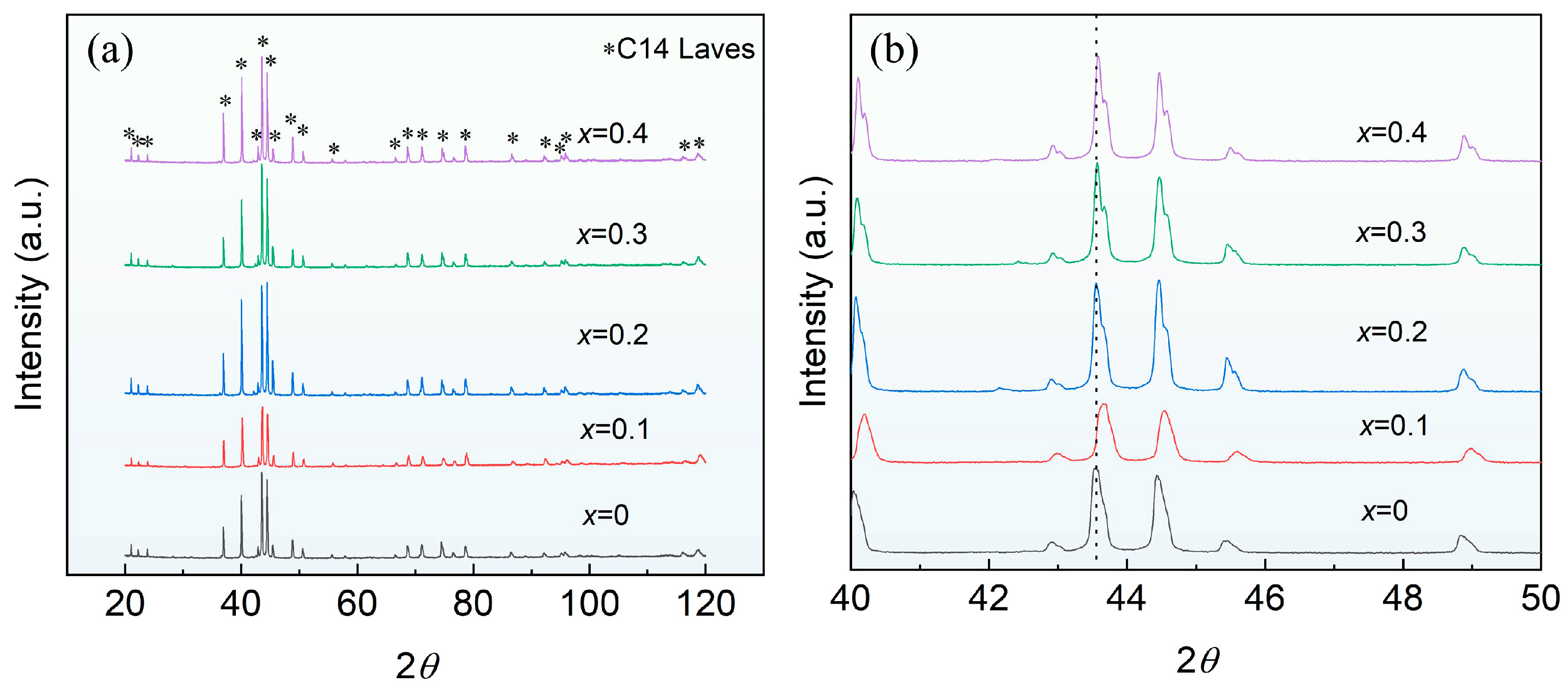
The corresponding XRD patterns of the fabricated Ti0.94Zr0.08Cr1.0Mn0.6−xFe0.4+x (x = 0, 0.1, 0.2, 0.3, 0.4) alloys are shown in Figure 1a. XRD analysis reveals that all the alloys consist of a single C14 Laves phase, indicating that the substitution of Fe for Mn does not change the phase composition. Figure 1b presents a magnified view of the main diffraction peaks. It can be seen that with the gradual increase in Fe substitution for Mn, the position of the main peak does not shift appreciably, suggesting that the Fe substitution does not significantly alter the lattice parameters of the alloys. In addition, no significant effect is observed on the intensity or full width at half maximum (FWHM) of the main peaks. The diffraction peak at around 41.6° corresponds to the (0 2 1) plane. The absence of an obvious shift in the main peak position further confirms that the lattice parameters remain essentially unchanged. Although the atomic radius of Mn is 135 pm and that of Fe is 124 pm [2], this negligible change in lattice parameters is primarily attributed to the relatively small amount of Fe substitution.
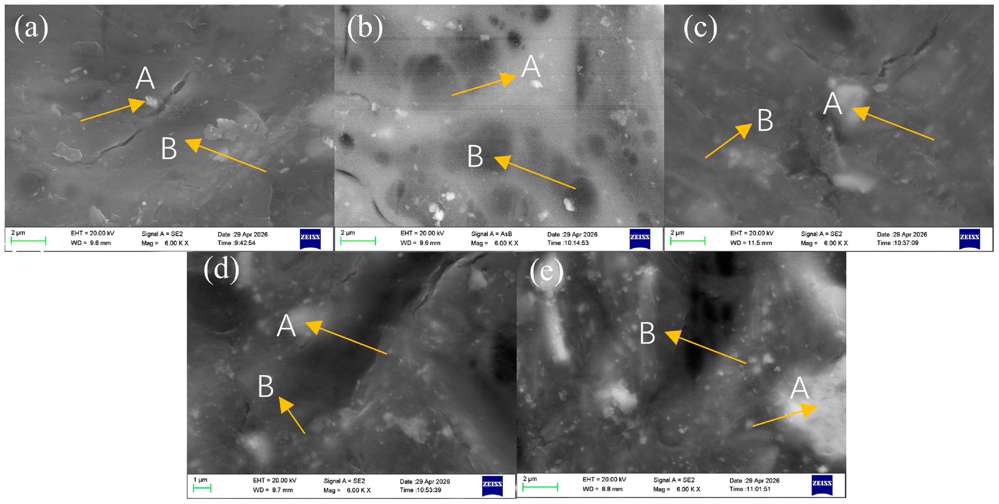
Figure 2 shows the backscattered electron (BSE) images of the Ti0.94Zr0.08Cr1.0Mn0.6−xFe0.4+x (x = 0, 0.1, 0.2, 0.3, 0.4) alloys. The SEM micrographs reveal two distinct contrast regions: brighter regions (marked as A) and darker regions (marked as B). This contrast difference is generally associated with local variations in the average atomic number, implying compositional inhomogeneity at the microscale. Notably, as the Fe content increases at the expense of Mn, the contrast between the two regions and their volume fractions remain essentially unchanged across the entire compositional range.
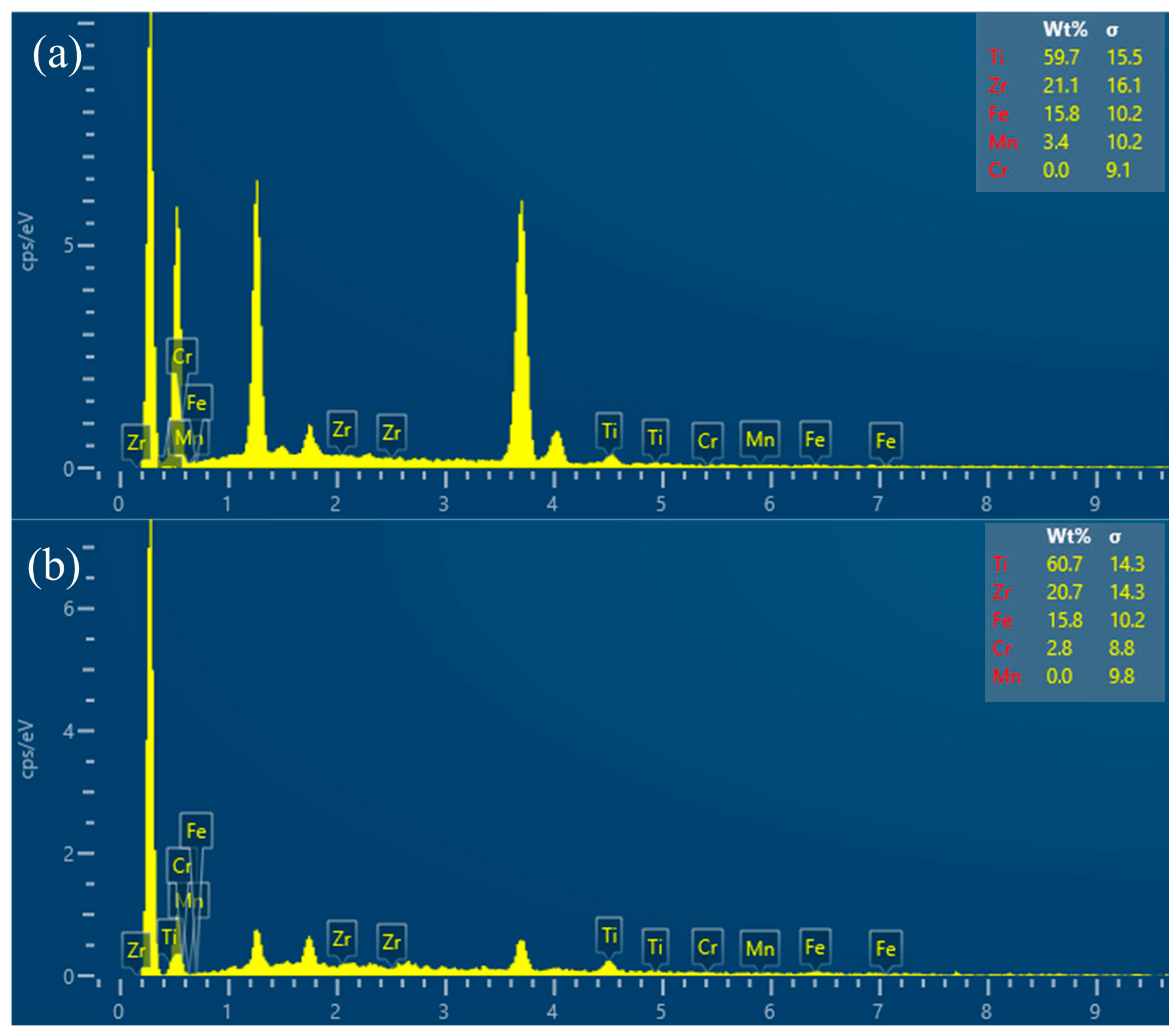
To identify the chemical nature of these regions, EDS analysis was performed on selected areas (Figure 3). Although the EDS results indicate certain compositional differences between regions A and B, no secondary phases were detected in the corresponding XRD patterns (Figure 1); all alloys still exhibit a single C14 Laves phase. It can therefore be inferred that the contrast variation observed in the BSE images does not originate from phase separation, but rather from local compositional fluctuations within the same Laves phase. This finding demonstrates that the C14 Laves phase in this alloy system possesses a wide compositional solid-solution range, accommodating a substantial degree of Fe-for-Mn substitution without undergoing phase transformation. Such compositional flexibility is characteristic of Laves phases, attributable to their topologically close-packed structure and the presence of multiple crystallographic sites that can be occupied by different atoms. The XRD results further confirm that, despite the microscale compositional inhomogeneities revealed by SEM, all alloys remain single-phase at the macroscopic level.
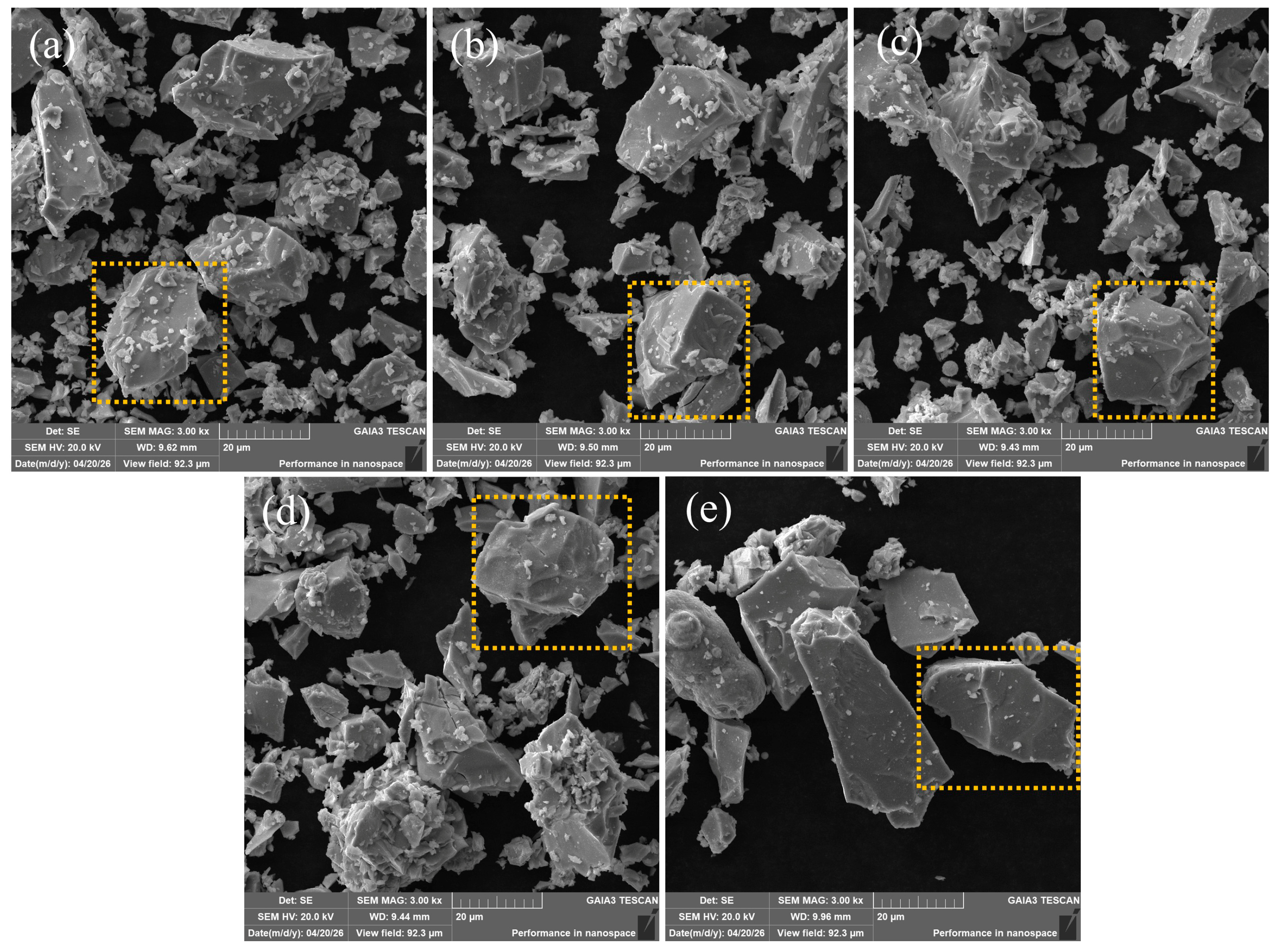
Figure 4 shows the SEM morphology of the studied AB2-type hydrogen storage alloy particles after mechanical crushing and sieving through a 200-mesh screen. Owing to the intrinsic brittleness of the alloy [12], the crushed particles exhibit a typical irregular angular shape with sharp edges, and distinct cleavage fracture steps as well as a few intergranular fracture features are observed on the surfaces; some larger particles are also covered with fine debris or contain incipient microcracks. Although the nominal aperture of the 200-mesh sieve is approximately 74 μm, the majority of the resulting particles are mainly concentrated at sizes of 20 μm or below. For hydrogen storage alloys, particle morphology and size distribution directly affect the activation performance, hydrogen absorption/desorption kinetics, and resistance to pulverization during cycling. Smaller particle sizes are more favorable for alloy activation, which is the advantage of nanostructuring hydrogen storage alloys. The irregular morphology increases the geometric specific surface area, which facilitates the adsorption and dissociation of hydrogen molecules on the alloy surface, thereby shortening the incubation period for activation [13]. EDS mapping was performed on the region enclosed by the yellow dashed line in the figure; details are given later.
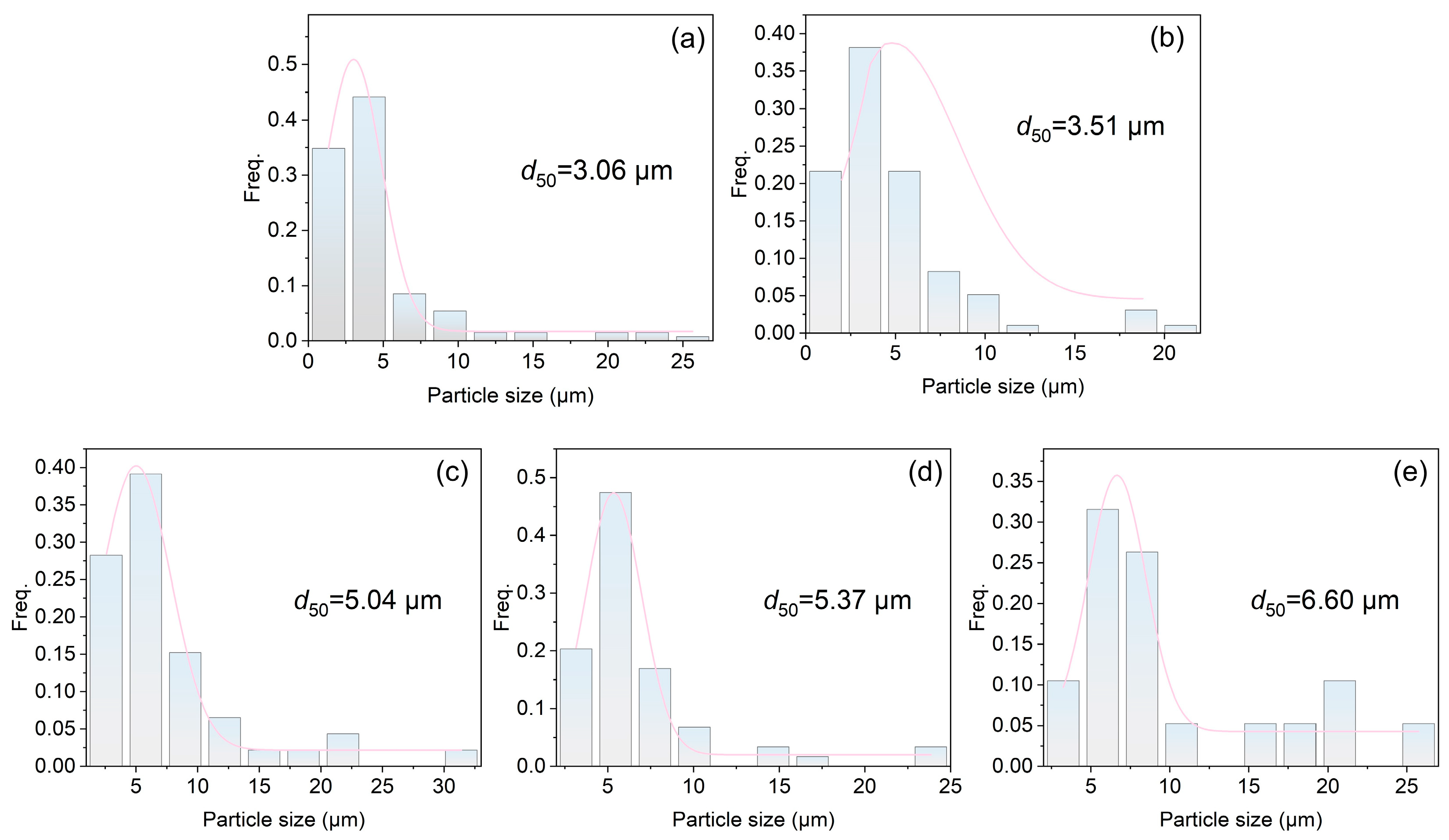
Figure 5 presents the particle size distribution of the alloy powders obtained from SEM image statistics. As shown, with increasing substitution of Mn by Fe, the median particle size d50 gradually increases from 3.06 μm to 6.60 μm, indicating that the Fe-for-Mn substitution exerts a notable influence on the comminution behavior of the alloy. This progressive coarsening of particles can be primarily attributed to the solid-solution strengthening effect induced by the partial replacement of Mn with Fe, which causes lattice distortion and thereby enhances the microhardness and resistance to plastic deformation of the alloy [14]. Under identical mechanical crushing conditions, the hardened alloy becomes more difficult to further pulverize into finer fractions, resulting in a relatively higher proportion of coarse particles and consequently leading to the observed continuous increase in d50 with rising Fe content. This finding also indirectly highlights the significant role of compositional tuning in governing the intrinsic mechanical properties and downstream powder processing characteristics of hydrogen storage alloys.
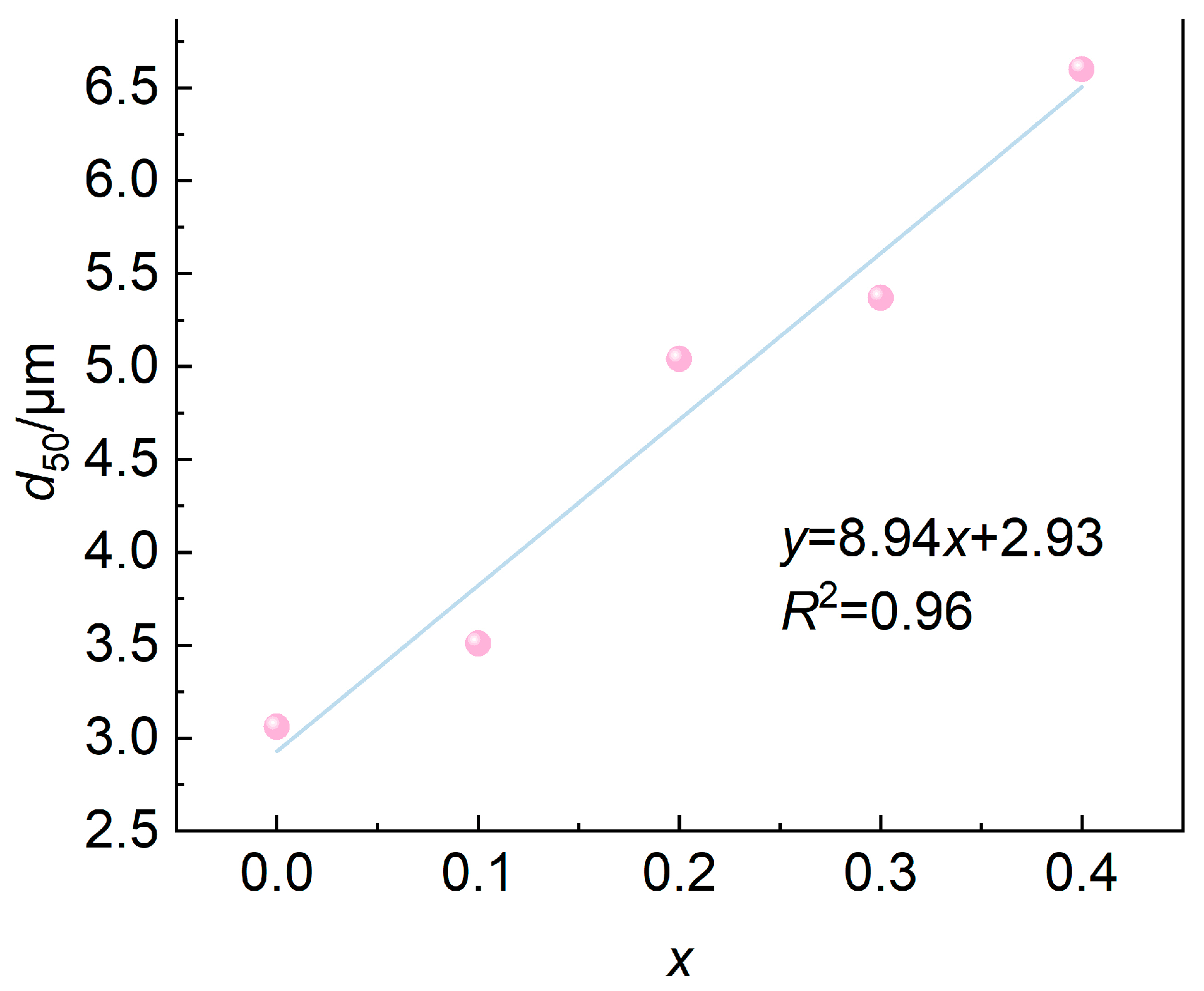
Figure 6 presents the variation in the median particle size d50 with the Fe substitution content x for Mn. It is clearly observed that d50 exhibits a good linear positive correlation with increasing x, i.e., d50 increases approximately linearly with x. This phenomenon has rarely been reported in previous studies on the comminution behavior of hydrogen storage alloy powders, and thus deserves particular attention.
The observed linear relationship is believed to arise primarily from the changes in the intrinsic mechanical properties of the alloy induced by the substitution of Mn by Fe. On the one hand, the difference in atomic radii between Fe and Mn gives rise to lattice distortion, resulting in a pronounced solid-solution strengthening effect, which enhances the microhardness and resistance to plastic deformation of the alloy. On the other hand, under identical mechanical crushing conditions, it is more difficult to comminute materials with higher hardness into finer fractions under impact loading. Consequently, as the Fe content (i.e., the x value) gradually increases from 0 to 0.4, the median particle size of the crushed powders tends to increase linearly.
Furthermore, the linear rather than nonlinear dependence between d50 and x may imply that, within the investigated composition range (where the variation in x is limited), the degree of solid-solution strengthening is approximately proportional to the substitution amount, and the energy input during crushing and the resistance to fracture reach a quasi-steady state, leading to a simple linear response of particle refinement to compositional changes. Nevertheless, whether this linear relationship holds universally remains to be verified over a broader composition range and in more alloy systems.
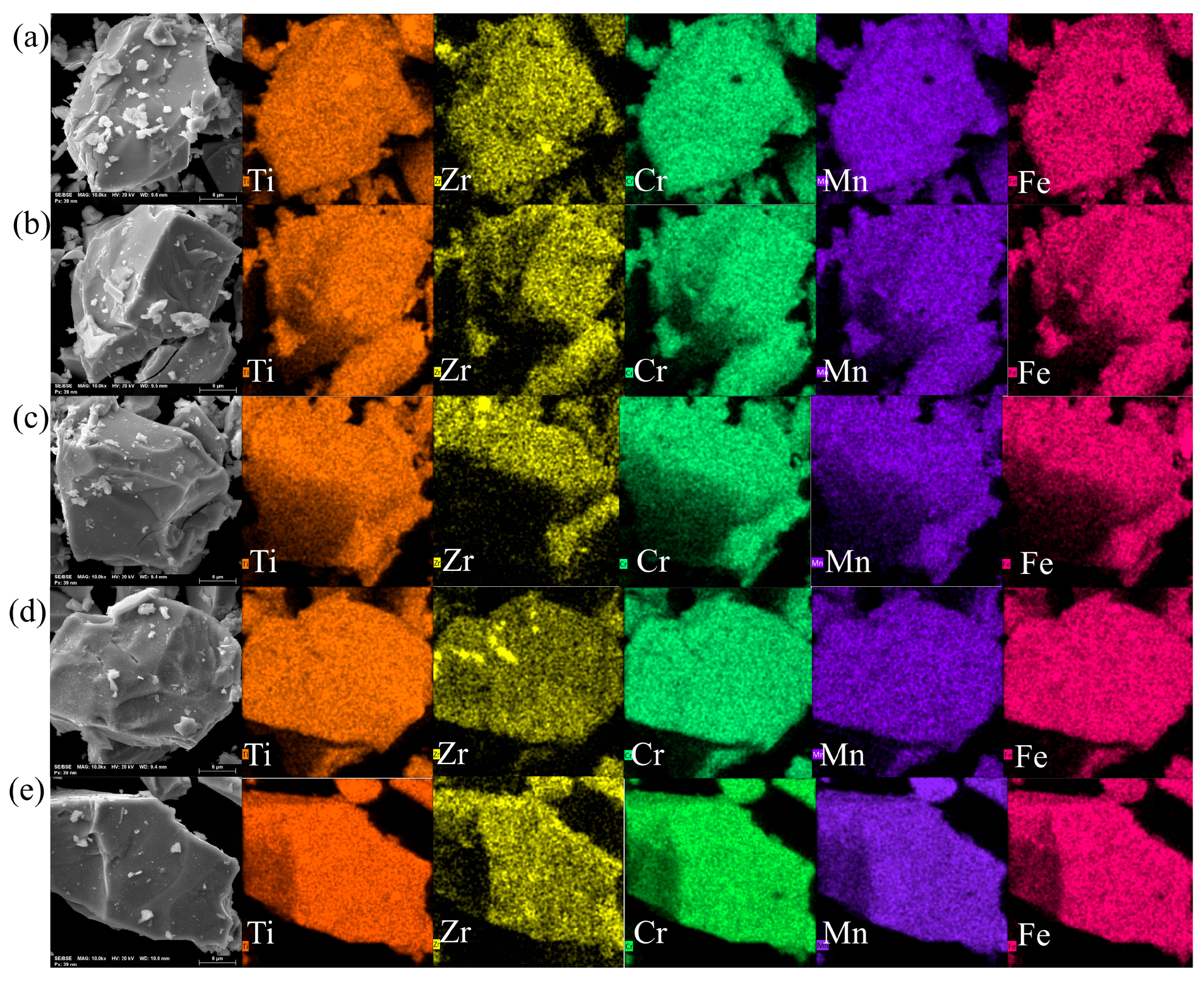
Figure 7 presents the EDS elemental mapping results of the selected area within the particles shown in Figure 4. The compositional distribution maps clearly reveal that, at the micrometer scale, the constituent elements of the alloy are highly uniformly distributed, with no obvious elemental segregation, agglomeration, or localized enrichment being observed. This finding indicates that the alloy exhibits good compositional homogeneity both within and among the particles after mechanical crushing, which is beneficial for ensuring the stability and reproducibility of its hydrogen storage performance.
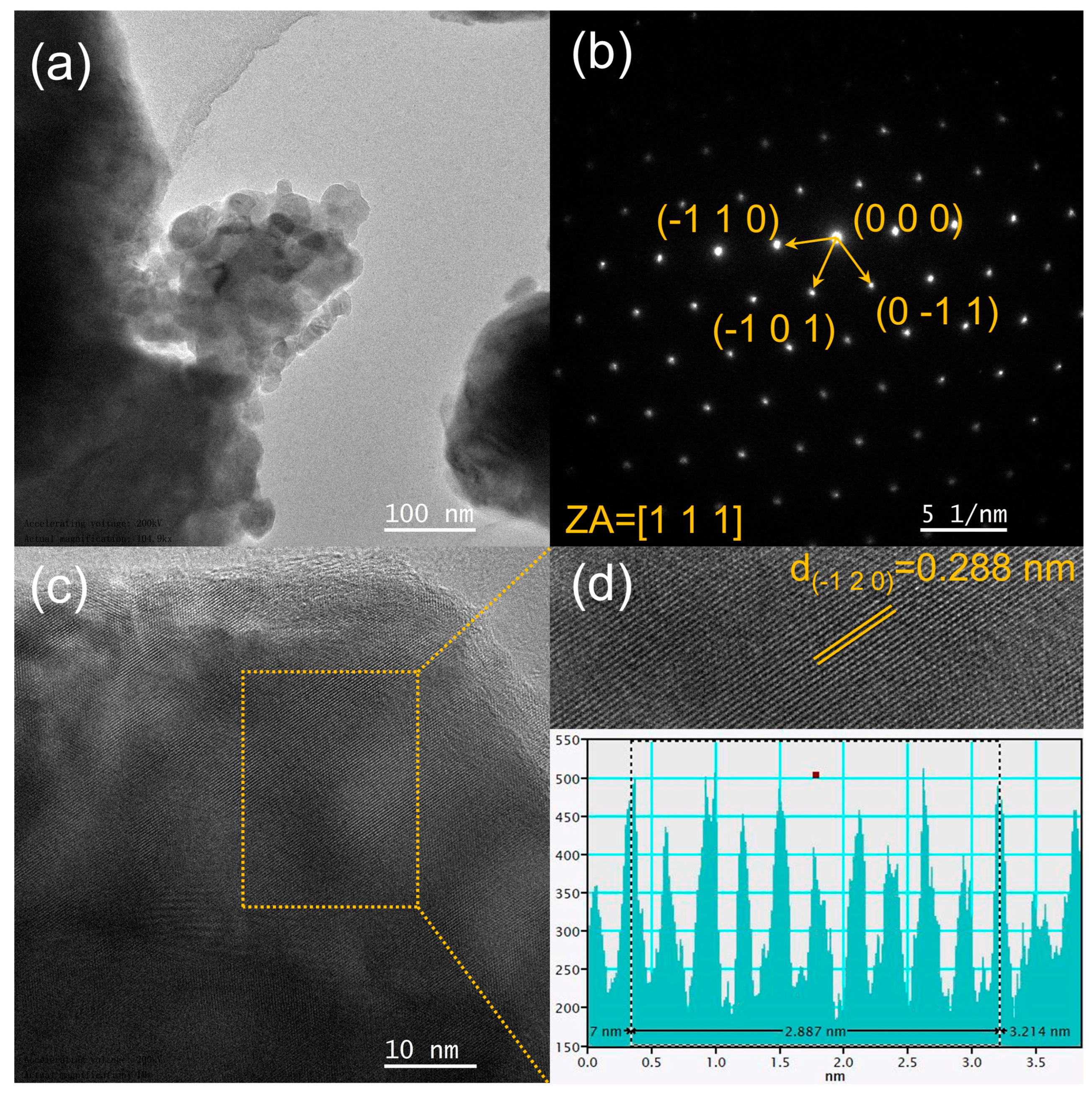
Figure 8 presents the TEM characterization results of the representative Ti0.94Zr0.08Cr1.0Mn0.4Fe0.6 alloy. The bright-field TEM image (Figure 8a) reveals the overall morphology and grain size of the alloy, showing a dense and relatively homogeneous microstructure with no obvious precipitates or defects at the observed scale. The selected area electron diffraction (SAED) pattern taken from the same region is shown in Figure 8b. It exhibits well-defined periodic diffraction spots that can be unequivocally indexed to the hexagonal MgZn2-type C14 Laves phase [15], with no extra reflections attributable to other phases. This single-orientation pattern confirms the absence of secondary phases, which is fully consistent with the XRD results (Figure 1). The high-resolution TEM (HRTEM) image (Figure 8c) further reveals clear and continuous lattice fringes with very limited lattice distortion, indicating that the alloy possesses a well-crystallized structure and a high degree of atomic ordering. The interplanar spacing measured from the HRTEM image (Figure 8d) using DiffTools (Version 7) [16] is approximately 0.288 nm, in good agreement with the (−1 2 0) plane of the C14 Laves phase. The narrow distribution of the measured fringe spacings and the absence of noticeable lattice defects suggest that the substitution of Fe for Mn has not introduced significant local strain or disorder, corroborating the invariant lattice parameters observed in the XRD analysis. Overall, the TEM observations provide direct microscopic evidence for the phase purity and structural stability of the alloy across the entire compositional range, reinforcing the conclusion that the C14 Laves phase can accommodate substantial Fe-for-Mn substitution while maintaining a highly ordered single-phase structure.

3.2. Hydrogen Compression Properties

3.2.1. Kinetic Properties

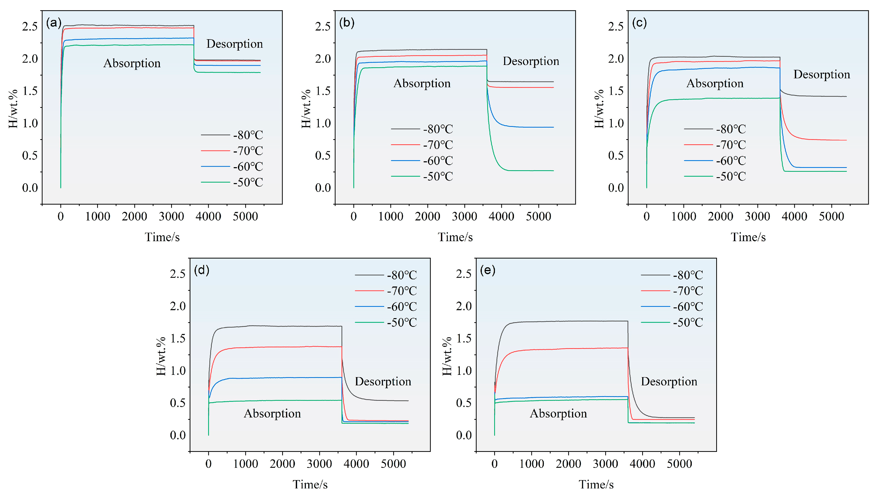
Figure 9 presents the hydrogen absorption/desorption kinetic curves for the alloys. It is evident that the hydrogen storage capacity at a given temperature decreases progressively with increasing Fe content. For instance, at an operating temperature of −80 °C, the absorption capacity drops from 2.51 wt.% for x = 0 to 1.77 wt.% for x = 4. The reason is possibly related to the atomic masses of Fe (55.85) and Mn (54.94). In contrast, the desorption kinetics reveal a clear increase in the effective desorption capacity with higher Fe content: at −80 °C, the values rise sequentially from 0.54 wt.% to 0.58 wt.%, 0.62 wt.%, 1.16 wt.%, and finally 1.50 wt.% as x increases.
For all alloys, the absorption kinetics are relatively rapid, with approximately 90% of the saturated capacity reached within about 200 s. Additionally, for a given alloy composition, a higher operating temperature leads to a lower hydrogen absorption capacity.

3.2.2. PCI Curves and Hydrogen Compression Properties

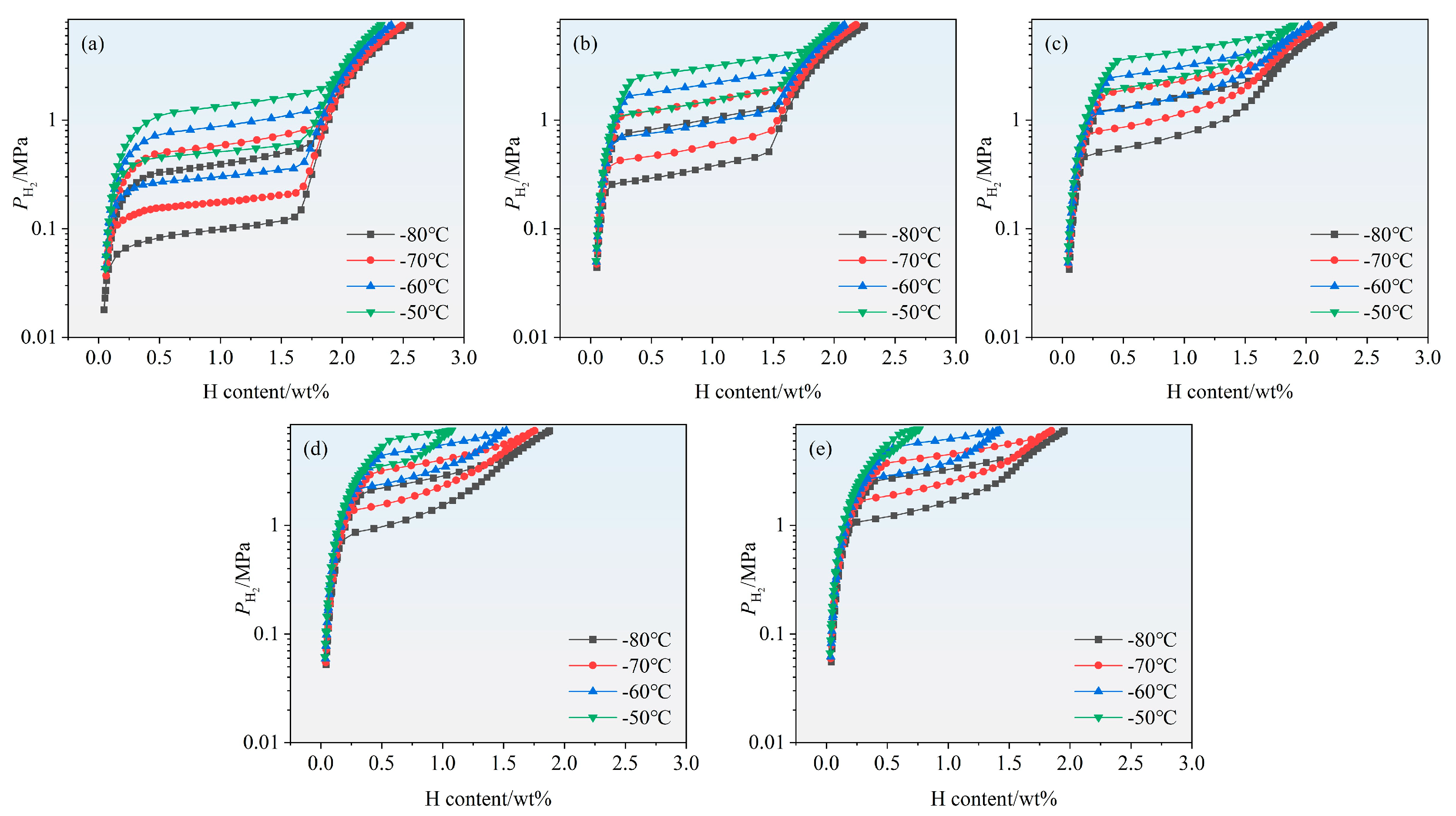
Figure 10 shows the PCI curves characterizing the hydrogen ab/de-sorption of the Ti0.94Zr0.08Cr1.0Mn0.6−xFe0.4+x (x = 0, 0.1, 0.2, 0.3, 0.4) alloys measured at −80, −70, −60 and −50 °C. All compounds exhibit a single plateau region. An increase in the stoichiometric parameter x tends to raise the plateau pressure, i.e., an increase in the Fe/Mn ratio leads to a higher plateau pressure. For the five compounds, the maximum capacity at −80 °C ranges from 1.70 wt.% to 2.50 wt.%, while at −60 °C it ranges from 0.70 wt.% to 2.50 wt.%. It is generally observed that the maximum hydrogen absorption capacity of AB2 compounds, whether of C14-type [17] or C15-type [18], is around 2.0 wt.%, which is consistent with our results. Reports in the literature indicate that some AB2 compounds exhibit a second plateau at higher pressures and/or lower temperatures, such as TiCr1.8 (C15-type) [19], TiCr1.9 (C14-type) [19], and even TiCr1.5Mn0.5 (C14-type) [19]. For TiCr1.5Mn0.5, Beeri et al. observed this second plateau at −77 °C and 35 MPa, but in the present study, no second plateau appears within the set pressure and temperature ranges. Under our operating conditions, it is confirmed that all compounds have fully absorbed hydrogen at least within the first plateau region. As for the plateau slope, these samples show a slightly inclined plateau, and the degree of inclination does not change significantly with the Fe/Mn ratio; however, the plateau pressure clearly increases with increasing Fe/Mn ratio. These results indicate that compositional tuning through adjusting Mn and Fe contents can raise the plateau pressure.
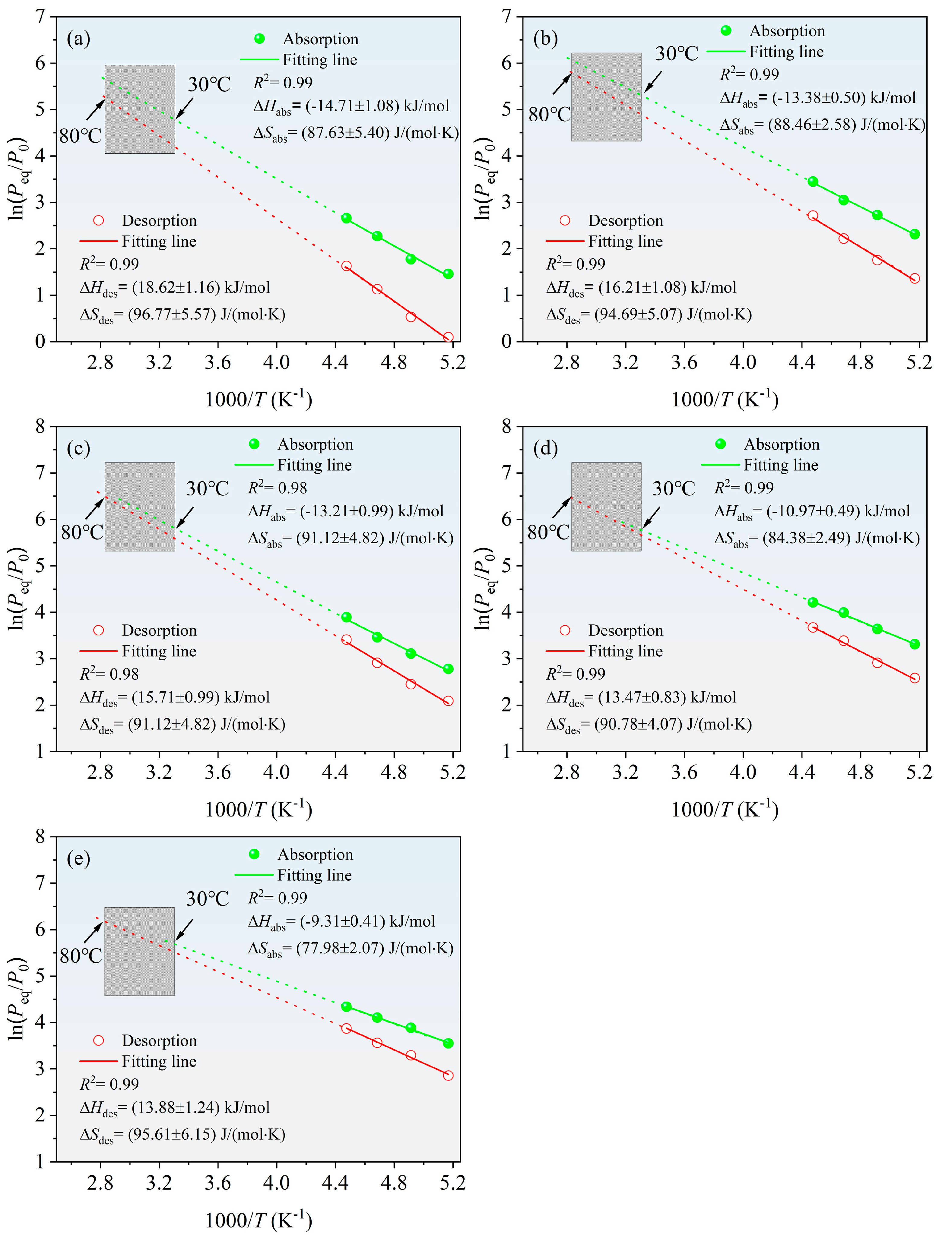
To calculate the enthalpy and entropy changes for hydride formation and decomposition, the corresponding Van’t Hoff plots are shown in Figure 11, and the values of enthalpy and entropy changes are summarized in Table 2. The increase in Fe content leads to a decrease in the absolute value of the enthalpy change. However, the measured ΔS values are slightly lower than the generally accepted value of 125 J/K/mol H2 for gas–solid reactions [20].
To evaluate the applicability of the developed alloys in a metal hydride (MH) thermally driven compressor, the present study sets typical operating conditions as hydrogen absorption at 30 °C and desorption at 80 °C. In this conceptual compressor cycle, the absorption plateau pressure determines whether the alloy can effectively capture low-pressure hydrogen at the lower temperature, while the desorption plateau pressure directly affects the capability of delivering high-pressure hydrogen. Since the pressure-composition (PC) isotherms at 30 °C and 80 °C were not fully measured for all alloys, we extrapolated the absorption pressures to 30 °C based on the Van’t Hoff relationships obtained from other measured temperatures, combined with fugacity corrections (corresponding to the absorption branch of the Van’t Hoff plots, shown as solid lines in Figure 11). The calculated results indicate that the absorption equilibrium pressures of all alloys at this temperature fall within the range of 11 MPa to 33 MPa (see Table 3 for details), which covers the target inlet pressure of approximately 30 MPa expected for a first-stage high-pressure hydrogen storage or compression system [21]. This suggests that these alloys possess good hydrogen capture capability at relatively low temperatures and show potential as materials for the primary or intermediate stage of the compressor.
For the hydrogen desorption pressure at 80 °C, due to experimental limitations, we did not directly measure the PC isotherms at this temperature. However, based on the Van’t Hoff plots for absorption and desorption reactions (with the dashed lines in Figure 11 representing the high-temperature extrapolated portions) and the enthalpy change (ΔH) derived from the slopes, the high-temperature desorption equilibrium pressure can be reasonably estimated. Specifically, since the entropy change (ΔS) and enthalpy change during the desorption process remain essentially constant, the desorption plateau pressure at 80 °C can be extrapolated by using the equation ln P = ΔH/(RT) − ΔS/R, combined with the obtained ΔH and ΔS values. The estimated results are also summarized in Table 3. Although this method relies on extrapolation, its reliability is relatively high based on the linearity of the thermodynamic relationship, and it can provide an effective reference for compressor performance evaluation. This approach is commonly adopted in the research of hydrogen compression materials. For example, Min Zhu et al. [22] measured the PCT isotherms of a Ti–Cr–Mn–Fe-based alloy at −50, −40, −30, and −20 °C, and then used the Van’t Hoff extrapolation to estimate the absorption pressure at 24.5 °C and the desorption pressure at 89.5 °C.
Based on the above estimated absorption and desorption pressures, we further calculated the compression factor (i.e., the ratio of desorption pressure to absorption pressure) for each alloy within this operating temperature range. This parameter serves as a key indicator for evaluating the single-stage pressure-boosting capability of the compressor. The results show that with the gradual substitution of Mn by Fe (i.e., with increasing Fe/Mn ratio), the compression factor exhibits a trend of first increasing and then decreasing, reaching a maximum value of 1.99 at x = 0.2. This non-monotonic variation may be related to the combined evolution of lattice parameters, plateau slope, and absorption–desorption hysteresis effects. An appropriate amount of Fe substitution for Mn can optimize the unit cell dimensions and improve the stability differences of hydrogen in the lattice, thereby reducing the absolute value of the enthalpy change for desorption, which favors an increase in the high-temperature desorption pressure. However, excessive Fe substitution may lead to non-uniform phase structures or an increased plateau slope, thereby weakening the effective pressure-boosting capability. The maximum compression factor approaching 2 indicates that this conceptual compressor can achieve nearly a two-fold pressure increase under the conditions of hydrogen absorption at 30 °C and desorption at 80 °C, demonstrating promising engineering application prospects.

4. Conclusions

In this study, we systematically investigated the effects of partial substitution of Mn by Fe on the microstructure, hydrogen storage thermodynamics, and hydrogen compression performance of Ti0.94Zr0.08Cr1.0Mn0.6−xFe0.4+x (x = 0–0.4) alloys. XRD and TEM confirm that all alloys retain a single C14 Laves phase structure, with no secondary phases detected, indicating that the C14 phase tolerates extensive Fe-for-Mn substitution. SEM-EDS reveals microscale compositional inhomogeneity within the same phase, but this does not compromise the phase purity. The median particle size after crushing increases linearly as x increases from 0 to 0.4, which is attributed to solid solution strengthening due to the smaller Fe atoms. Hydrogen absorption kinetics are fast, reaching 90% of saturated capacity within 200 s, but the maximum storage capacity declines with increasing Fe content, whereas the effective desorption capacity improves noticeably. Pressure–composition isotherms show flat single plateaus, and the plateau pressure rises systematically with Fe/Mn ratio. The calculated enthalpy change for desorption decreases in magnitude from 18.62 to 13.08 kJ/mol H2 as x increases from 0 to 0.4, while entropy values remain around 90 J/K/mol H2, slightly below the conventional value for gas–solid reactions. From Van’t Hoff extrapolations to practical operating temperatures (30 °C absorption, 80 °C desorption), the compression factor first increases and then decreases, peaking at 1.99 for both x = 0.2 and x = 0.3. The x = 0.2 alloy offers the best balance of plateau pressure, reversible capacity, and compression ratio. Overall, moderate Fe substitution is an effective strategy to tune plateau pressures for target compression applications, and the optimized alloy shows promising potential for low-grade waste-heat-driven hydrogen compressors in refueling stations.

Author Contributions

Conceptualization, Y.D., L.L., T.D., Y.W., Y.H., and X.Z.; methodology, Y.W. and T.D.; software, Y.H.; validation, Y.D., L.L., T.D., Y.W., Y.H., and X.Z.; formal analysis, Y.D. and Y.W.; investigation, L.L., T.D., and X.Z.; resources, L.L. and T.D.; data curation, Y.D. and Y.H.; writing—original draft preparation, Y.D.; writing—review and editing, Y.D., L.L., T.D., Y.W., Y.H., and X.Z.; visualization, L.L. and X.Z.; supervision, L.L.; project administration, L.L.; funding acquisition, L.L. All authors have read and agreed to the published version of the manuscript.

Funding

This work was supported by Inner Mongolia Rare Earth Ovonic Metal Hydride Co., Ltd. through the commissioned project entitled “High-Entropy Design and Development of Solid-State Hydrogen Storage Alloys (NKDHX2026017)”; the Natural Science Foundation of Inner Mongolia, China (2026MS0558); and the Inner Mongolia Autonomous Region Major Science and Technology Project–Rare Earth Special Project: Research and Application Demonstration of Key Technologies for Distributed Solid-State Hydrogen Storage and Power Generation Systems in Multiple Scenarios.

Data Availability Statement

The original contributions presented in this study are included in the article material. Further inquiries can be directed to the corresponding author.

Acknowledgments

We would like to thank the Analytical and Testing Center of Inner Mongolia University of Science & Technology for its strong support in XRD, SEM, TEM and DSC testing.

Conflicts of Interest

Authors Yuan Deng, Tao Deng, Yongguang Wang and Yi Huangfu were employed by the company “Inner Mongolia Rare Earth Ovonic Metal Hydride Co., Ltd.” The remaining authors declare that the research was conducted in the absence of any commercial or financial relationships that could be construed as a potential conflict of interest.

References

  1. Prakash, K.S.J.; Sharma, V.K. Recent developments on metal hydride hydrogen compressors–A comprehensive review. J. Alloys Compd. 2025, 1037, 182505. [Google Scholar] [CrossRef] [Scilit]
  2. Luo, L.; Yu, K.; Chen, L.; Han, H.; Deng, Y.; Chen, B.; Cheng, Y.; Li, Y.; Zhang, X. Optimizing the microstructure of high-entropy alloys to achieve efficient hydrogen storage at room temperature. Nano Res. 2026, 19, 94908396. [Google Scholar] [CrossRef] [Scilit]
  3. Hassan, I.; Ramadan, H.S.; Saleh, M.A.; Hissel, D. Hydrogen storage technologies for stationary and mobile applications: Review, analysis and perspectives. Renew. Sustain. Energy Rev. 2021, 149, 111311. [Google Scholar] [CrossRef] [Scilit]
  4. Luo, L.; Chen, L.; Li, L.; Liu, S.; Li, Y.; Li, C.; Li, L.; Cui, J.; Li, Y. High-entropy alloys for solid hydrogen storage: A review. Int. J. Hydrogen Energy 2024, 50, 406–430. [Google Scholar] [CrossRef] [Scilit]
  5. Parida, A.; Muthukumar, P.; Dalal, A. A review on non-mechanical hydrogen compressors for hydrogen refuelling stations. Int. J. Hydrogen Energy 2025, 145, 292–321. [Google Scholar] [CrossRef] [Scilit]
  6. Xu, J.; Qin, C.; Wang, H. C15-Structured Zr-Ti-Fe-Ni-V Alloys for High-Pressure Hydrogen Compression. Materials 2025, 18, 5482. [Google Scholar] [CrossRef] [Scilit] [PubMed]
  7. Singh, U.R.; Bhogilla, S.S.; Sou, H.; Itoko, S.; Tolj, I. Performance evaluation of hybrid compressors for hydrogen storage and refuelling stations. J. Energy Storage 2025, 114, 115778. [Google Scholar] [CrossRef] [Scilit]
  8. Cousins, A.; Kinaev, N.; Edwards, S.; Langley, M.; Gray, E.M. Understanding the Application Envelope for Metal Hydride Compressors (Techno-Economic Considerations). Hydrogen 2026, 7, 35. [Google Scholar] [CrossRef] [Scilit]
  9. Cao, Z.; Zhou, P.; Xiao, X.; Zhan, L.; Jiang, Z.; Piao, M.; Wang, S.; Jiang, L.; Chen, L. Studies on Ti-Zr-Cr-Mn-Fe-V based alloys for hydrogen compression under mild thermal conditions of water bath. J. Alloys Compd. 2022, 892, 162145. [Google Scholar] [CrossRef] [Scilit]
  10. Zhou, P.; Cao, Z.; Xiao, X.; Zhan, L.; Li, S.; Li, Z.; Jiang, L.; Chen, L. Development of Ti-Zr-Mn-Cr-V based alloys for high-density hydrogen storage. J. Alloys Compd. 2021, 875, 160035. [Google Scholar] [CrossRef] [Scilit]
  11. Peng, Z.; Li, Q.; Ouyang, L.; Jiang, W.; Chen, K.; Wang, H.; Liu, J.; Li, Z.; Wang, S.; Zhu, M. Overview of hydrogen compression materials based on a three-stage metal hydride hydrogen compressor. J. Alloys Compd. 2022, 895, 162465. [Google Scholar] [CrossRef] [Scilit]
  12. Philipose, S.M.; Mani, N.; Kesavan, T.; Ramaprabhu, S. Investigations of hydrogen storage properties in certain Zr-based AB2 alloys. Int. J. Hydrogen Energy 2002, 27, 419–424. [Google Scholar] [CrossRef] [Scilit]
  13. Tao, G.; Zhang, H.; Li, A.; Xue, X.; Zhang, Y.; Zhang, Y.; He, T.; Wang, H.; Liu, Y. Effect of alloy particle size and device internal structure on the de-/hydriding properties of Ti-Zr-Cr-Mn based hydrogen storage alloys. Int. J. Hydrogen Energy 2025, 173, 151029. [Google Scholar] [CrossRef] [Scilit]
  14. Jiang, W.; Chen, S.; Shen, H.; Cao, Z.; He, C.; Yang, X.; Ouyang, L. Influence of Fe substitution on structural stability and hydrogen storage/compression performance: A theoretical and experimental study on TiCr1.5−xMn0.5Fex alloys. Chem. Eng. J. 2024, 494, 153243. [Google Scholar] [CrossRef] [Scilit]
  15. Yartys, V.A.; Lototskyy, M.V. Laves type intermetallic compounds as hydrogen storage materials: A review. J. Alloys Compd. 2022, 916, 165219. [Google Scholar] [CrossRef] [Scilit]
  16. Mitchell, D.R.G. DiffTools: Software Tools for Electron Diffraction in DigitalMicrograph. Microsc. Res. Tech. 2008, 71, 588–593. [Google Scholar] [CrossRef] [Scilit] [PubMed]
  17. Park, J.-G.; Jang, H.-Y.; Han, S.-C.; Lee, P.S.; Lee, J.-Y. Hydrogen storage properties of TiMn2-based alloys for metal hydride heat pump. Mater. Sci. Eng. A 2002, 329–331, 351–355. [Google Scholar] [CrossRef] [Scilit]
  18. Mitrokhin, S.; Zotov, T.; Movlaev, E.; Verbetsky, V. Hydrogen interaction with intermetallic compounds and alloys at high pressure. J. Alloys Compd. 2013, 580, S90–S93. [Google Scholar] [CrossRef] [Scilit]
  19. Beeri, O.; Cohen, D.; Gavra, Z.; Mintz, M. Sites occupation and thermodynamic properties of the TiCr2−xMnx–H2 (0≤x≤1) system: Statistical thermodynamics analysis. J. Alloys Compd. 2003, 352, 111–122. [Google Scholar] [CrossRef] [Scilit]
  20. Shao, H.; Xu, H.; Wang, Y.; Li, X. Preparation and hydrogen storage properties of Mg2Ni intermetallic nanoparticles. Nanotechnology 2004, 15, 269–274. [Google Scholar] [CrossRef] [Scilit]
  21. Charbonnier, V.; Enoki, H.; Asano, K.; Kim, H.; Sakaki, K. Tuning the hydrogenation properties of Ti1+yCr2−xMnx laves phase compounds for high pressure metal-hydride compressors. Int. J. Hydrogen Energy 2021, 46, 36369–36380. [Google Scholar] [CrossRef] [Scilit]
  22. Peng, Z.; Li, Q.; Sun, J.; Chen, K.; Jiang, W.; Wang, H.; Liu, J.; Ouyang, L.; Zhu, M. Ti-Cr-Mn-Fe-based alloys optimized by orthogonal experiment for 85 MPa hydrogen compression materials. J. Alloys Compd. 2022, 891, 161791. [Google Scholar] [CrossRef] [Scilit]
Figure 1. XRD patterns of the Ti0.94Zr0.08Cr1.0Mn0.6−xFe0.4+x (x = 0, 0.1, 0.2, 0.3, 0.4) alloys: (a) 2θ = 20–120°, (b) 2θ = 40–50°.
Metals 16 00965 g001
Figure 2. The SEM images of Ti0.94Zr0.08Cr1.0Mn0.6−xFe0.4+x (x = 0, 0.1, 0.2, 0.3, 0.4) alloys: (a) x = 0, (b) x = 0.1, (c) x = 0.2, (d) x = 0.3, and (e) x = 0.4.
Metals 16 00965 g002
Figure 3. EDS analysis of representative Ti0.94Zr0.08Cr1.0Mn0.2Fe0.8 alloy: (a) region A, (b) region B marked in Figure 2.
Metals 16 00965 g003
Figure 4. SEM morphology of the Ti0.94Zr0.08Cr1.0Mn0.6−xFe0.4+x (x = 0, 0.1, 0.2, 0.3, 0.4) alloy particles after sieving through a 200-mesh screen. (a) x = 0, (b) x = 0.1, (c) x = 0.2, (d) x = 0.3, and (e) x = 0.4.
Metals 16 00965 g004
Figure 5. Particle size analysis of the Ti0.94Zr0.08Cr1.0Mn0.6−xFe0.4+x (x = 0, 0.1, 0.2, 0.3, 0.4) alloy particles after sieving through a 200-mesh screen. (a) x = 0, (b) x = 0.1, (c) x = 0.2, (d) x = 0.3, and (e) x = 0.4.
Metals 16 00965 g005
Figure 6. Variation in the particle size d50 of the alloys with the Fe substitution content x for Mn.
Metals 16 00965 g006
Figure 7. EDS elemental mapping of the selected area within the particles shown in Figure 4. (a) x = 0, (b) x = 0.1, (c) x = 0.2, (d) x = 0.3, and (e) x = 0.4.
Metals 16 00965 g007
Figure 8. TEM characterization of the representative Ti0.94Zr0.08Cr1.0Mn0.4Fe0.6 alloy: (a) bright-field image, (b) selected area electron diffraction (SAED) pattern, (c) high-resolution TEM (HRTEM) image, and (d) magnified HRTEM view with interplanar spacing measurement.
Metals 16 00965 g008
Figure 9. The hydrogen absorption/desorption kinetic curves of Ti0.94Zr0.08Cr1.0Mn0.6−xFe0.4+x (x = 0, 0.1, 0.2, 0.3, 0.4) alloys. (a) x = 0, (b) x = 0.1, (c) x = 0.2, (d) x = 0.3, and (e) x = 0.4.
Metals 16 00965 g009
Figure 10. PC-isotherms for the Ti0.94Zr0.08Cr1.0Mn0.6−xFe0.4+x (x = 0, 0.1, 0.2, 0.3, 0.4) alloys measured at −80, −70, −60 and −50 °C. (a) x = 0, (b) x = 0.1, (c) x = 0.2, (d) x = 0.3, and (e) x = 0.4.
Metals 16 00965 g010
Figure 11. Van’t Hoff plots of Ti0.94Zr0.08Cr1.0Mn0.6−xFe0.4+x (x = 0, 0.1, 0.2, 0.3, 0.4) alloys. The solid lines are the Van’t Hoff plots, and the curves have been extrapolated and are shown as dashed lines. (a) x = 0, (b) x = 0.1, (c) x = 0.2, (d) x = 0.3, and (e) x = 0.4.
Metals 16 00965 g011
Table 1. ICP elemental analysis results.
Nominal CompositionsAtomic Percentages (at.%)
TiZrMnCrFe
Ti0.94Zr0.08Mn0.6Cr1.0Fe0.430.324.3017.8634.2513.30
Ti0.94Zr0.08Mn0.5Cr1.0Fe0.528.602.9215.5336.0016.95
Ti0.94Zr0.08Mn0.4Cr1.0Fe0.629.882.6211.3735.9520.17
Ti0.94Zr0.08Mn0.3Cr1.0Fe0.729.662.147.3136.1424.76
Ti0.94Zr0.08Mn0.2Cr1.0Fe0.829.772.463.7036.0528.02
Table 2. Absorption and dissociation pressures at −80 °C, −70 °C, −60 °C and −50 °C; enthalpies and entropies of absorption and desorption of Ti0.94Zr0.08Cr1.0Mn0.6−xFe0.4+x (x = 0, 0.1, 0.2, 0.3, 0.4) alloys.
AlloysT (°C)Cabs (wt.%)Pa (MPa)Pd (MPa)ΔHabs (kJ⸱mol−1 H2)ΔSabs (J/K/mol H2)ΔHdes (kJ⸱mol−1 H2)ΔSdes (J/K/mol H2)
x = 0−802.550.430.10−14.71 ± 1.0887.63 ± 5.4018.62 ± 1.1696.77 ± 5.57
−702.490.590.17
−602.390.970.31
−502.301.430.51
x = 1−802.231.010.39−13.38 ± 0.5088.46 ± 2.5816.21 ± 1.0894.69 ± 5.07
−702.171.530.58
−602.082.110.92
−501.993.151.51
x = 2−802.221.780.81−13.21 ± 0.9991.12 ± 4.8215.71 ± 0.9991.12 ± 4.82
−702.112.241.16
−602.023.181.84
−501.894.913.02
x = 3−801.872.741.32−10.97 ± 0.4984.38 ± 2.4913.47 ± 0.8390.78 ± 4.07
−701.753.801.84
−601.515.422.95
−501.076.743.93
x = 4−801.943.471.74−9.31 ± 0.4177.98 ± 2.0713.08 ± 1.2495.61 ± 6.15
−701.844.862.69
−601.426.073.52
−500.757.665.82
Table 3. Absorption and dissociation pressures at 30 °C and 80 °C (estimated from the Van’t Hoff plots); compression factor of Ti0.94Zr0.08Cr1.0Mn0.6−xFe0.4+x (x = 0, 0.1, 0.2, 0.3, 0.4) alloys.
AlloysInlet Pressure (MPa) (Calculated)Outlet Pressure (MPa) (Calculated)Outlet Pressure (MPa) (Calculated)Compression Factor
Pin (30 °C)Pout (30 °C)Pout (80 °C) P des ( 80   ° C ) P abs ( 30   ° C )
x = 011.76.4718.81.61
x = 120.213.132.71.62
x = 232.326.764.51.99
x = 333.028.465.81.99
x = 430.824.949.21.59
Disclaimer/Publisher’s Note: The statements, opinions and data contained in all publications are solely those of the individual author(s) and contributor(s) and not of MDPI and/or the editor(s). MDPI and/or the editor(s) disclaim responsibility for any injury to people or property resulting from any ideas, methods, instructions or products referred to in the content.