Article

Effect of Thickness on Connection Strength and Pull-Out Behavior of TiNiFe Shape Memory Alloy Pipe Couplings


1
State Key Laboratory of Nonferrous Structural Materials, China GRINM Group Co., Ltd., Beijing 100088, China
2
Key Laboratory for Advanced Materials Processing (MOE), Institute for Advanced Materials and Technology, University of Science and Technology Beijing, Beijing 100083, China
3
GRIMAT Engineering Institute Co., Ltd., Beijing 101407, China
4
General Research Institute for Nonferrous Metals, Beijing 100088, China
5
Beijing Laboratory of Metallic Materials and Processing for Modern Transportation, Institute for Advanced Materials and Technology, University of Science and Technology Beijing, Beijing 100083, China
6
GRINM (Guangdong) Institute for Advanced Materials and Technology, Foshan 528051, China
*
Author to whom correspondence should be addressed.
Metals 2026, 16(4), 427; https://doi.org/10.3390/met16040427
Submission received: 10 March 2026 / Revised: 8 April 2026 / Accepted: 13 April 2026 / Published: 15 April 2026

Abstract

TiNiFe shape memory alloy pipe couplings exhibit excellent radial recovery capability and therefore show great potential for pipeline fastening applications. In this study, the radial recovery stresses at different locations within a TiNiFe SMA pipe coupling were determined using a finite element inverse method. These stresses were subsequently applied as boundary conditions to establish a numerical model describing the fastening connection and pull-out process between the TiNiFe coupling and a TA18 tube. The effects of coupling wall thickness on the connection state and pull-out failure behavior were systematically investigated. The results indicate that the radial recovery stress increases monotonically with increasing wall thickness, although the growth rate gradually decreases. When the wall thickness ranges from 1.25 to 1.75 mm, the interfacial contact stress increases with thickness, thereby enhancing the fastening effect. However, when the thickness exceeds 1.75 mm, the intensified radial deformation of the inner convexes leads to a significant reduction in contact stress. The pull-out process of the assembly can be divided into three stages, namely the initial, intermediate, and final stages, during which the pull-out force first increases and then decreases with the evolution of the contact state. These findings provide a theoretical basis for the structural optimization and engineering application of TiNiFe SMA pipe couplings.

1. Introduction

Shape memory alloys (SMAs), owing to their unique shape memory effect and superelasticity, have shown great potential for applications in pipeline connections, sealing structures, and fastening devices [1,2]. Among them, TiNi-based SMAs have been widely used in various structural joining components due to their excellent recovery capability, high strength, and good corrosion resistance [3,4,5]. By utilizing the radial recovery stress generated during the phase transformation of SMAs, reliable fastening connections between pipes can be achieved [6,7]. In particular, the transformation temperatures of TiNiFe alloys (As, Af, Ms, and Mf) can be precisely tailored by adjusting the Fe content, enabling their application in specific low-temperature operating environments [8]. Consequently, TiNiFe SMAs exhibit significant potential for engineering applications in pipe coupling and fastening systems [9,10].
The pipe coupling is first expanded at a low temperature so that its inner diameter becomes slightly larger than the outer diameter of the pipe. During assembly, the pipe is inserted into the coupling, followed by heating. The subsequent shape recovery of the coupling causes the inner diameter to shrink, thereby achieving a reliable fastening connection between the pipes [11]. In recent years, research on the connection performance of shape memory alloy pipe couplings has mainly focused on recovery stress characteristics, connection reliability, and failure behavior [12,13,14]. Several studies have experimentally investigated the stress evolution of SMA couplings during the assembly and recovery processes and have further explored the influence of structural parameters on connection performance [15,16].
However, due to the difficulty of directly measuring the radial recovery stress distribution inside shape memory alloy pipe couplings through experimental methods, most existing studies rely on indirect estimations or simplified assumptions for analysis [17,18]. This limitation restricts the accurate prediction of connection performance to some extent.
In addition, the influence of geometric parameters of the pipe coupling, such as wall thickness, on fastening performance and pull-out failure behavior has not yet been systematically investigated [19]. In practical engineering applications, the rational determination of coupling structural parameters is essential for ensuring connection reliability. Therefore, it is necessary to develop effective methods to determine the radial recovery stress distribution within SMA pipe couplings and to further investigate the influence of structural parameters on connection performance [20].
To address the aforementioned issues, this study proposes a finite element inverse method to determine the radial recovery stress distribution inside TiNiFe alloy pipe couplings [21,22]. The obtained stresses are then applied as boundary conditions to establish a numerical simulation model for the fastening connection and pull-out deformation between a TiNiFe pipe coupling and a TA18 tube. On this basis, the connection state and pull-out failure behavior of the coupling under different wall thicknesses are systematically investigated. Particular attention is given to the effects of wall thickness on contact stress distribution, radial deformation, and connection strength. The results of this study provide a theoretical reference for the structural optimization and engineering application of TiNiFe shape memory alloy pipe couplings.

2. Materials and Methods

2.1. Experiment Materials

2.1.1. TiNiFe Shape Memory Alloy Coupling

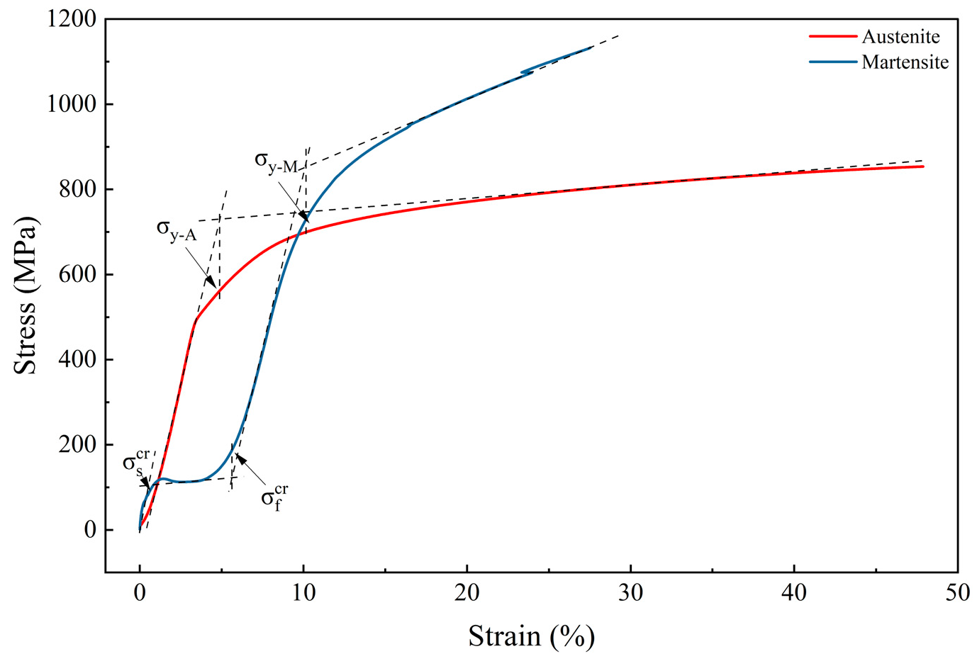
In this study, cold-rolled TiNiFe alloy bars were selected as the raw material and machined into specimens required for subsequent experiments. The initial bar diameter before machining was 12 mm, with its chemical composition listed in Table 1. Prior to testing, all specimens were subjected to vacuum heat treatment at 600 °C for 1 h, followed by furnace cooling to room temperature. Figure 1 presents the stress–strain curves of the TiNiFe alloy specimens obtained under uniaxial tensile loading after vacuum heat treatment. The tensile curve corresponding to the austenitic state was obtained at room temperature, whereas the tensile test for the martensitic state was conducted in a low-temperature chamber at −190 °C to ensure that the specimens were fully transformed into the martensitic phase.
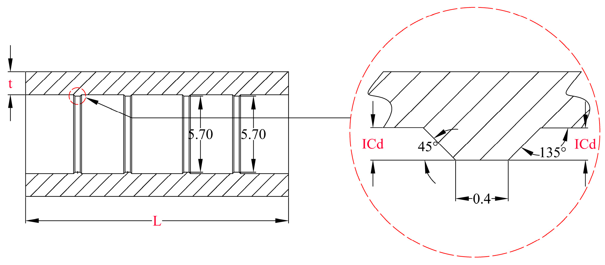
Figure 2 illustrates the schematic of the TiNiFe alloy pipe coupling, where the inner wall is machined with trapezoidal protrusions (inner convexes). Four inner convexees are symmetrically distributed along the axial direction to enhance the fastening performance between the pipe coupling and the mating tube. The structural parameters of the pipe coupling include its length (L), wall thickness (t), and inner convex depth (ICd). The inner convex depth (ICd) is defined as half of the difference between the inner diameter at the convex apex and the inner diameter of the tube wall. The inner diameter at the apex of each convex is 5.70 mm. This study focuses on the influence of wall thickness on the connection performance of TiNiFe alloy pipe couplings. The detailed dimensions of the pipe couplings for each group are summarized in Table 2.

2.1.2. TA18 Alloy Tube

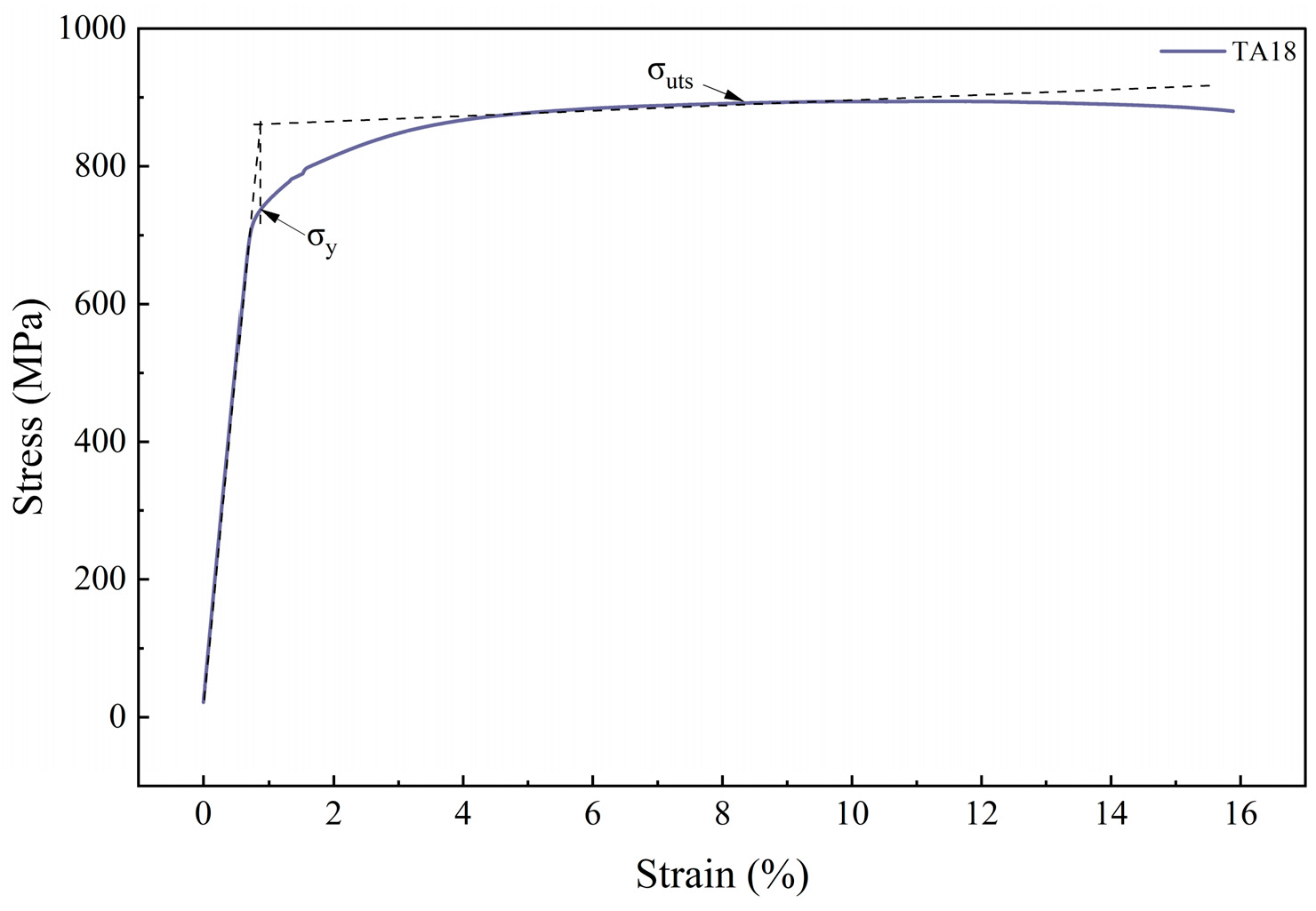
For the tube material used in the connections, commercially available TA18 titanium alloy tubes were selected. The mechanical properties of the TA18 tubes are shown in Figure 3. The elastic modulus of the TA18 tube is 105 GPa, with a yield strength of 740 MPa and a tensile strength of 890 MPa. The tubes have an inner diameter of 5.00 mm, an outer diameter of 6.00 mm, and a length of 100 mm.

2.2. Pull-Out Test

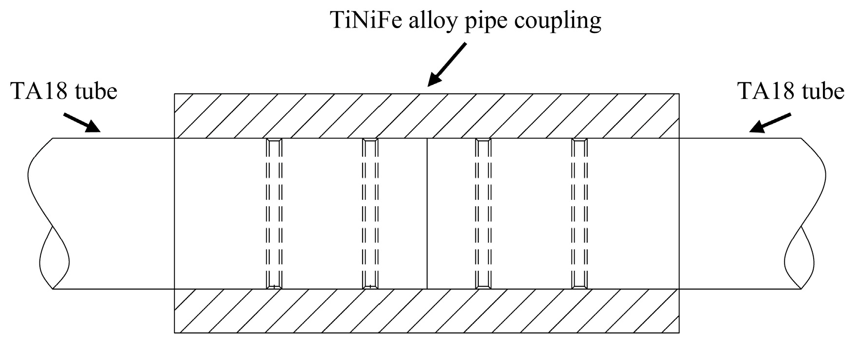
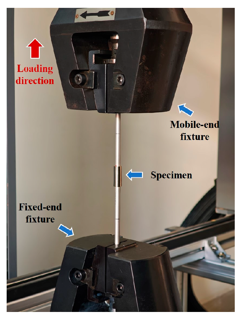
As shown in Figure 4, the TiNiFe alloy pipe coupling was assembled with two TA18 tubes to form a specimen for connection strength testing, which was then mounted on the testing apparatus depicted in Figure 5. The assembly process was carried out in a liquid nitrogen environment at approximately −196 °C. After assembly, the specimens were removed from the cryogenic environment and exposed to ambient air at room temperature (~25 °C). The reverse martensitic transformation was then naturally triggered by the temperature increase, leading to the recovery of the TiNiFe alloy and the formation of a tight interference fit with the TA18 tube.
Prior to installation, steel plugs were inserted into the ends of the tubes to provide positioning and support. The specimen was then securely fixed using upper and lower tube clamps. During loading, a uniaxial testing machine applied a tensile load at a constant displacement rate of 1 mm/min through the crosshead, gradually pulling the TA18 tubes out of the TiNiFe pipe coupling. A force sensor mounted above the apparatus continuously recorded the force–displacement response. The peak load on the curve was defined as the connection strength, serving as a quantitative measure of the TiNiFe pipe coupling’s connection performance.

3. Finite Element Simulation Model

3.1. Simulation Model

The numerical simulations in this study were conducted using the Abaqus finite element analysis platform. Since the Abaqus material library does not include a model capable of capturing the shape memory behavior of TiNiFe alloys, a user-defined material subroutine (UMAT) was implemented using Fortran, based on a previously established constitutive model for the TiNiFe alloy. The material parameters required by the UMAT subroutine were obtained from corresponding experimental tests, and their specific values are listed in Table 3. This approach allowed for an accurate representation of the mechanical behavior of the TiNiFe alloy in the finite element simulations.
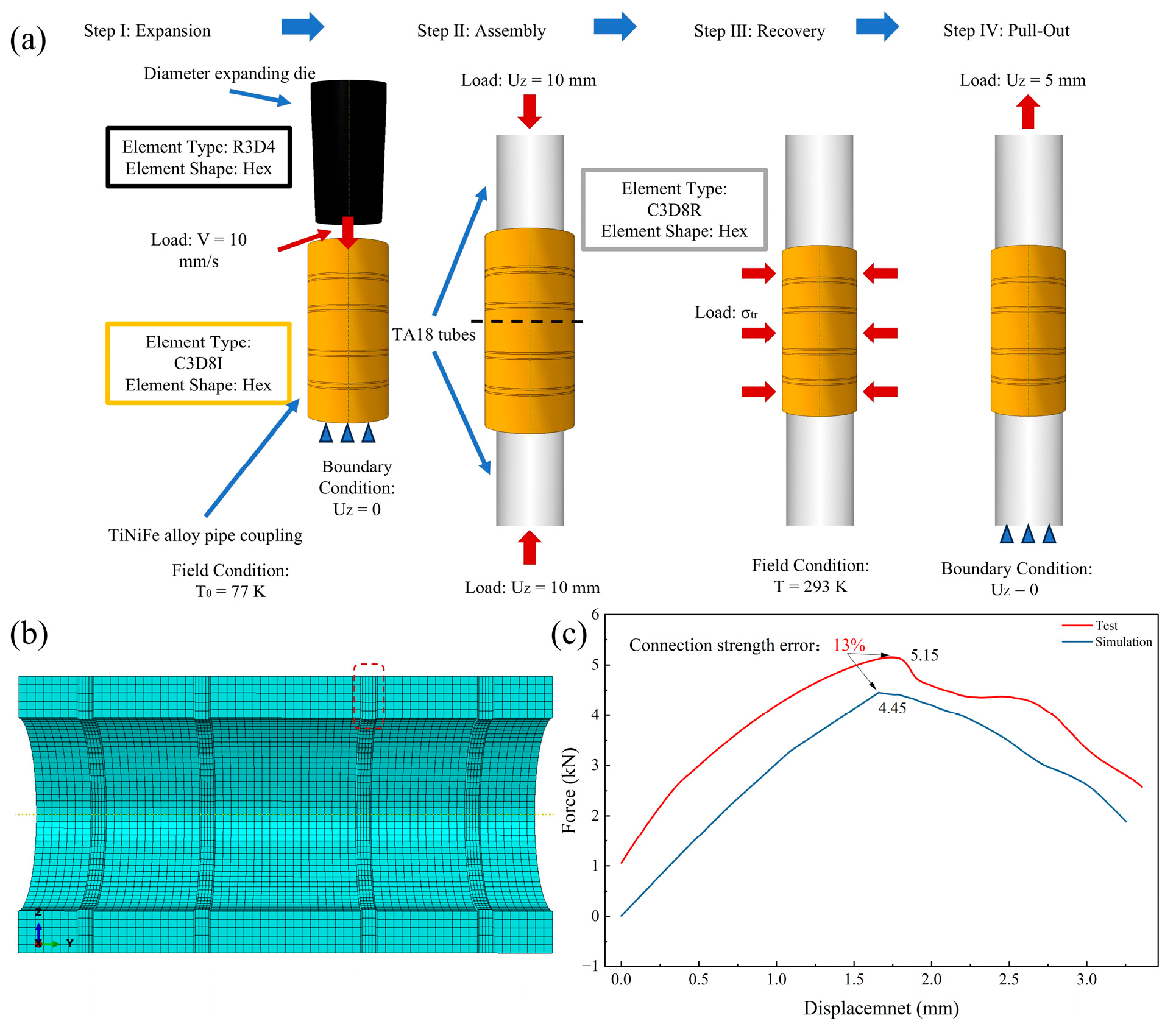
Figure 6 shows the full finite element simulation model of the TiNiFe alloy pipe coupling assembled with TA18 tubes. The boundary conditions and loading for each analysis step are illustrated in Figure 6a.
Step I: Expansion: The initial temperature was set to T0 = 77 K to ensure that the TiNiFe pipe coupling remained in the martensitic state. The pipe coupling was constrained with UZ = 0 to restrict axial movement. The expansion die was moved through the interior of the pipe coupling at a constant rate of 10 mm/s to complete the expansion process.
Step II: Tube Assembly: Displacement loads were applied to the TA18 tubes to position them into the specified assembly locations.
Step III: Shape Recovery: The field temperature was adjusted to T = 293 K, causing the TiNiFe alloy to gradually transform from martensite to austenite. Simultaneously, radial recovery stress σₜᵣ was applied to the inner wall of the pipe coupling. Through the shape recovery process, a tight connection between the pipe coupling and the assembled tubes was achieved. For pipe couplings with different internal geometries, the applied radial recovery stress varied, as detailed in Table 3.
Step IV: Pull-Out: One end of the tube was constrained with UZ = 0, while a displacement load of UZ = 3 mm was applied to the other end to partially extract the tube.
This study mainly focuses on Step III and Step IV to systematically investigate the fastening behavior of TiNiFe pipe couplings with different wall thicknesses and the subsequent pull-out failure process.
For the expansion die, a discrete rigid body was defined and meshed using hexahedral R3D4 rigid elements with an average element size of 0.3 mm, resulting in a total of 10,366 elements. The TiNiFe pipe coupling and the TA18 tubes were treated as deformable bodies. Due to the complex geometry of the pipe coupling’s inner wall, C3D8I hexahedral elements were employed to prevent hourglass effects and shear locking. The pipe coupling was meshed with an average element size of 0.25 mm, totaling 54,740 elements, with additional mesh refinement applied at critical regions such as the inner convexes. The TA18 tubes, having relatively simple geometry, were meshed using C3D8R hexahedral elements with an average element size of 0.2 mm, with each tube containing 30,360 elements.
The contact conditions were defined as follows:
Step I (Expansion): Surface-to-surface contact was established between the expansion die and the pipe coupling, with the die’s outer surface designated as the master surface and the pipe coupling’s inner wall as the slave surface. The normal contact behavior was defined using the default “hard” contact, while the tangential contact was set as frictional with no lubrication, using the “penalty” formulation and a friction coefficient of 0.15.
Step III (Shape Recovery): The contact between the pipe coupling and the tubes followed the same settings as Step I. The master and slave surfaces were adjusted to the pipe coupling inner wall and the tube outer surface, respectively, while all other contact parameters remained unchanged.
Figure 6c presents the validation results of the full simulation model of the assembled connection. The simulation results show good agreement with the experimental data in terms of the overall variation trend. The peak pull-out forces obtained from the experiment and simulation are 5.15 kN and 4.45 kN, respectively, with a deviation of approximately 13%. Overall, the comparison demonstrates that the proposed finite element model is capable of reasonably predicting the mechanical behavior of the TiNiFe alloy pipe coupling during the pull-out process.

3.2. Determination of Radial Recovery Stress Boundary Condition via Inverse Finite Element Method

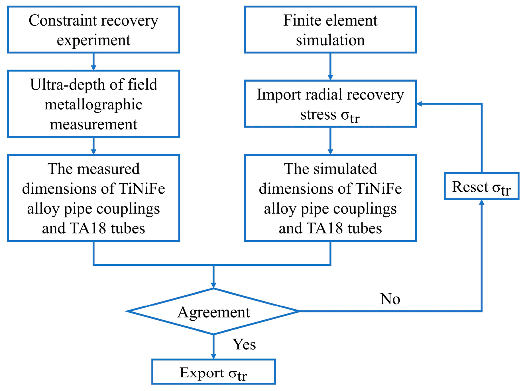
As shown in Figure 7, the radial recovery stress σₜᵣ of the TiNiFe pipe coupling during the fastening process was determined using the inverse finite element method. Due to the complex internal geometry of the pipe coupling, the inner diameter varies across different regions, resulting in different actual deformations at each location during pre-deformation. In addition, variations in wall thickness also affect the radial recovery stress. Therefore, in the finite element model, the magnitude of the applied radial recovery stress was adjusted separately for different locations. By comparing the simulated dimensions of the assembled coupling with experimental measurements, the values of σₜᵣ were iteratively corrected. The final radial recovery stress boundary conditions determined by the inverse finite element approach are listed in Table 4.

4. Results and Discussion

4.1. Analysis of the Fastening Connection State

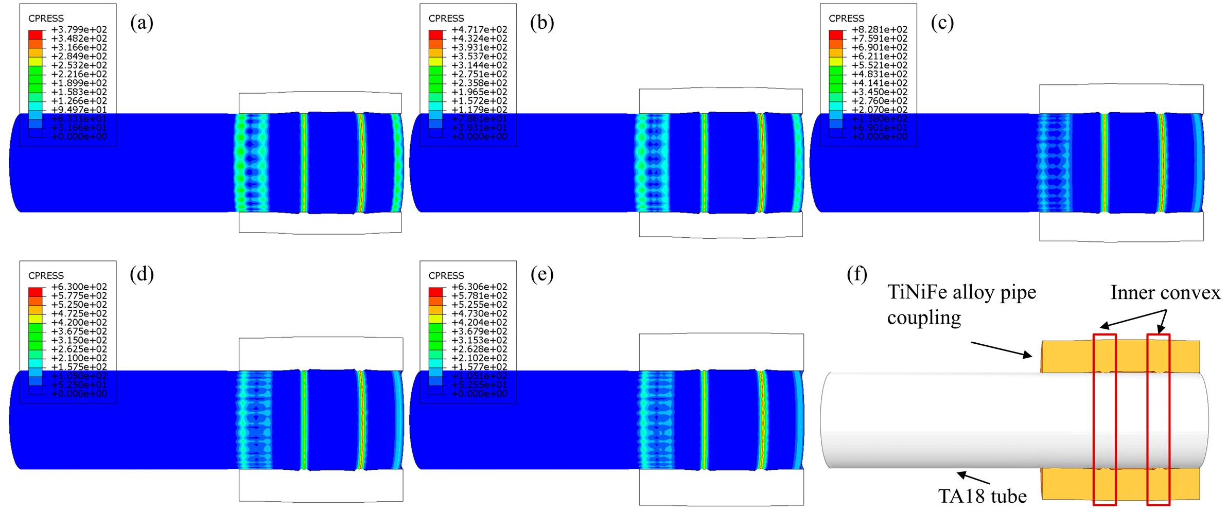
As shown in Figure 8, the contact stress distribution between the TiNiFe pipe coupling and the TA18 tubes was analyzed under different wall thicknesses (t). When t = 1.25 mm, the maximum contact stress on the mating surface was approximately 380 MPa. As the wall thickness increased from 1.25 mm to 1.75 mm, the maximum contact stress significantly rose to about 820 MPa, indicating a pronounced radial clamping effect of the inner convexes on the tubes. However, further increasing the wall thickness resulted in a decrease in contact stress to approximately 630 MPa. This suggests that excessive wall thickness increases the structural stiffness of the pipe coupling, thereby reducing its local radial deformability and weakening the effective clamping action of the inner convexes. Overall, the fastening performance of the pipe coupling exhibits a trend of first increasing and then decreasing with wall thickness. The maximum contact stress occurs at t ≈ 1.75 mm, corresponding to the optimal fastening condition.
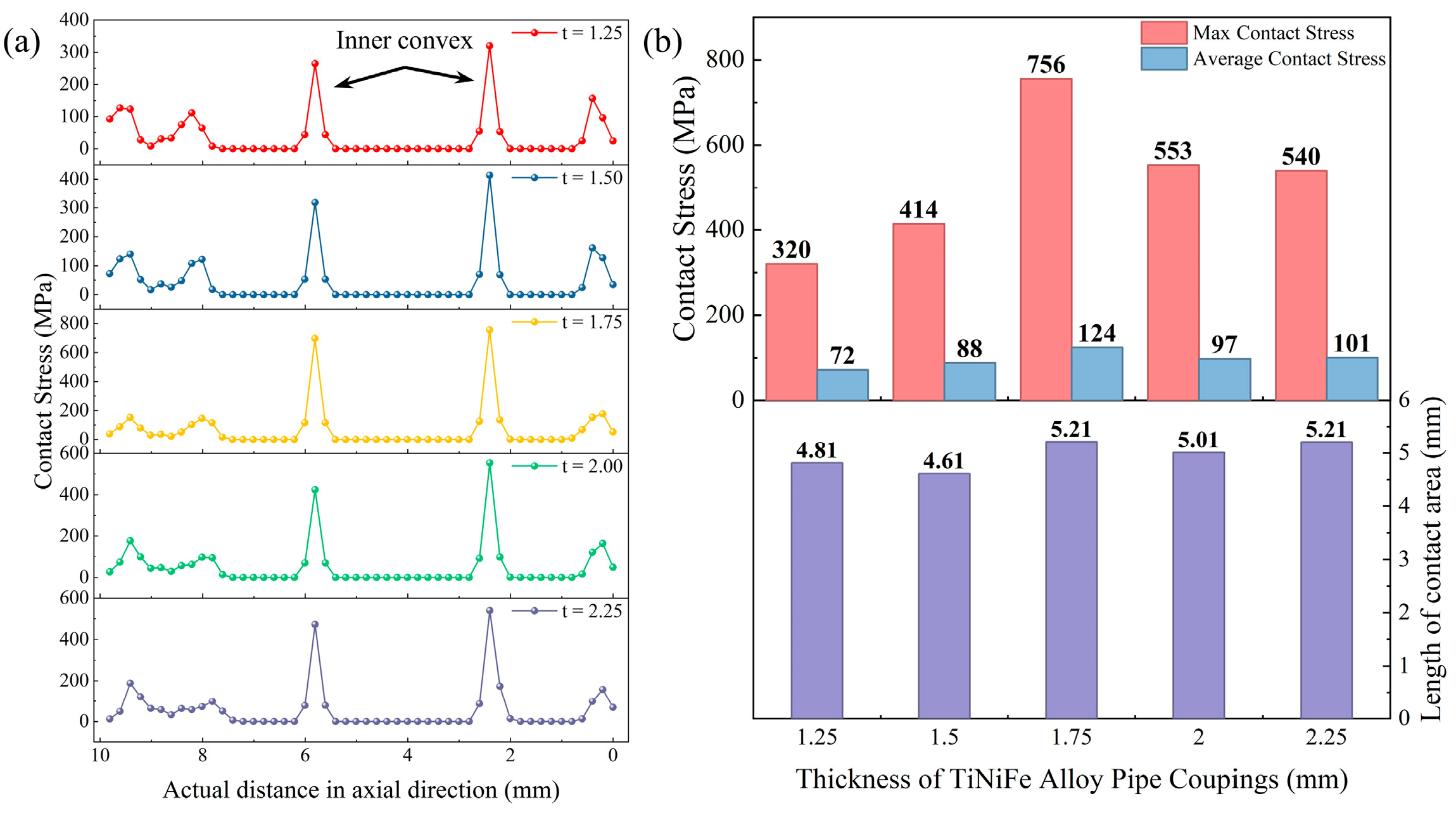
Axial distributions of the contact stress on the tube surfaces were extracted, and the results are presented in Figure 9a. For wall thicknesses in the range of 1.25 ≤ t ≤ 1.75 mm, the maximum contact stress in the regions contacting the inner convexes increased significantly with increasing wall thickness. When the wall thickness was further increased, the maximum contact stress decreased to approximately 540 MPa. Considering the radial recovery stress boundary conditions listed in Table 4, it can be seen that the radial recovery stress at different positions along the pipe coupling inner wall generally increases with wall thickness.
However, as shown in the statistical results of Figure 9b, changes in wall thickness primarily affect the maximum contact stress, while the length of the contact region is minimally influenced, and the variation in average contact stress remains limited. For t > 1.75 mm, the maximum contact stress is approximately 540 MPa, whereas the average contact stress stabilizes around 100 MPa. The decrease in contact stress with increasing wall thickness can be attributed to the reduction in circumferential strain under the same expansion displacement. A thicker wall leads to higher structural stiffness, which limits the recoverable deformation and consequently reduces the recovery-induced contact stress. These results indicate that a moderate increase in wall thickness enhances the radial recovery stress and is therefore beneficial for improving the fastening performance of the pipe coupling.
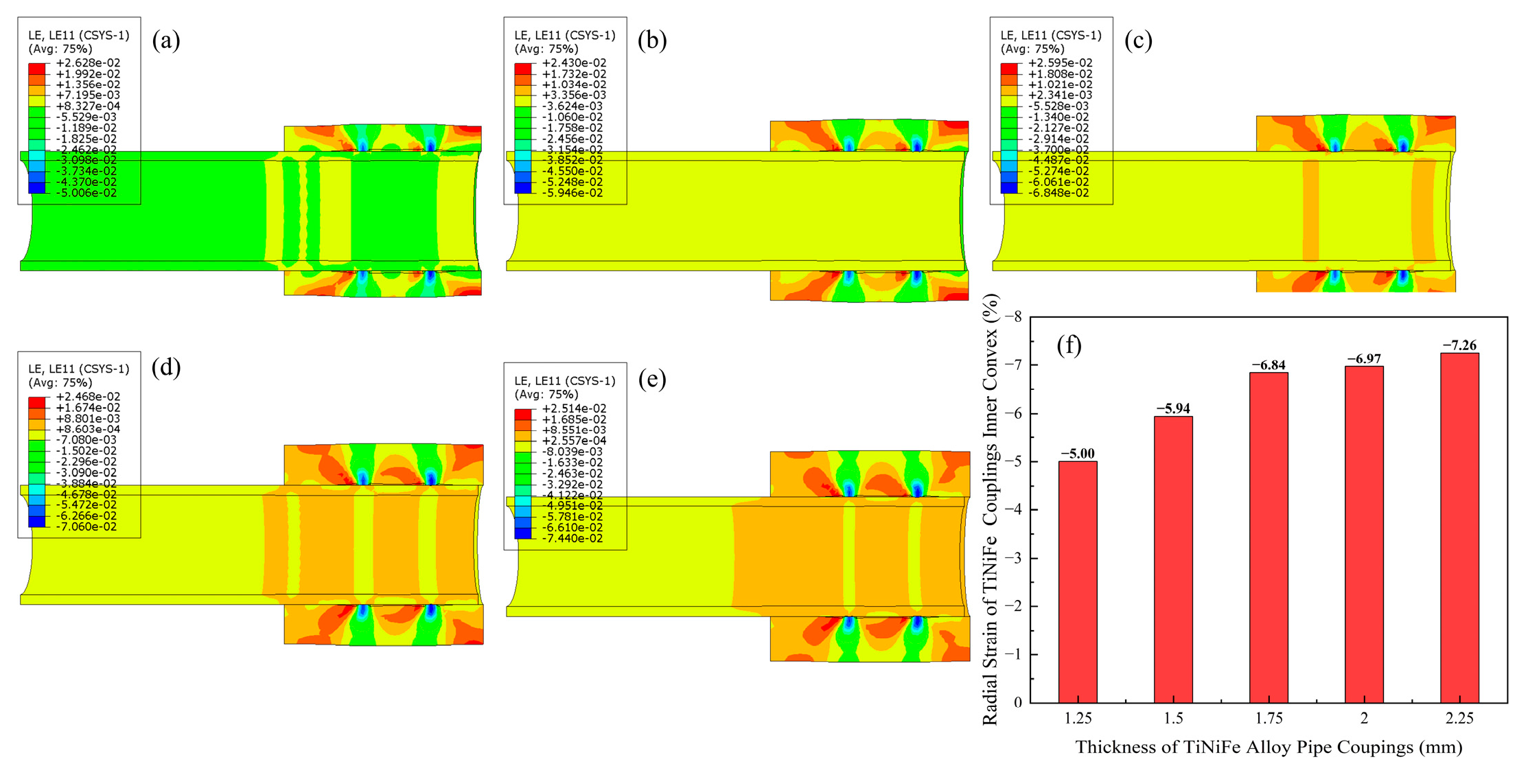
According to the radial strain distribution shown in Figure 10, as the wall thickness increased from 1.25 mm to 2.25 mm, the radial strain near the inner convexes exhibited a monotonic increase. This indicates that with increasing wall thickness, the radial deformation of the inner convex region becomes more pronounced upon completion of the fastening process. The increased deformation of the inner convexes reduces their clamping effect on the tubes, thereby diminishing the overall fastening performance. When t > 1.75 mm, the reduction in contact stress caused by the increased inner convex deformation outweighs the enhancement effect from the increased radial recovery stress, resulting in a significant decrease in contact stress in the inner convex region.
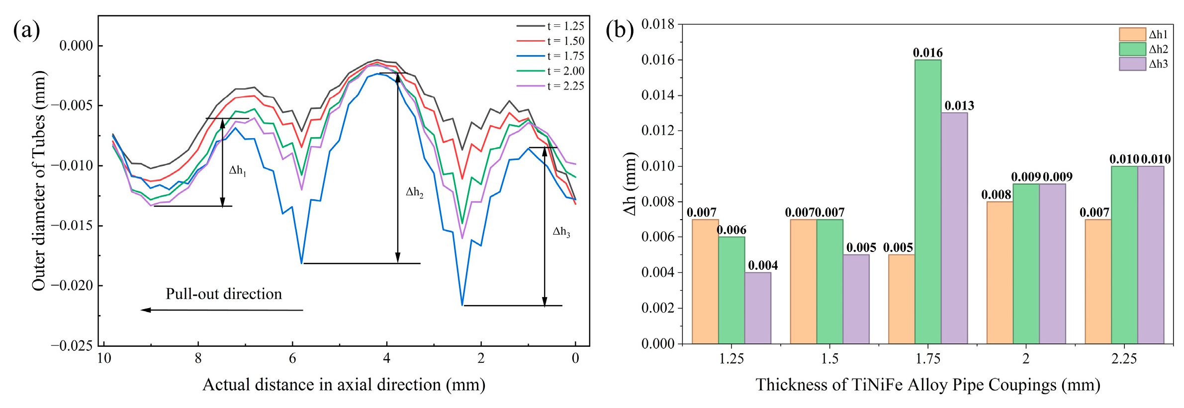
Figure 11 presents the radial displacement distribution on the tube contact surface upon completion of the fastening process. The radial displacement differences at different locations (Δh1, Δh2, and Δh3) reflect the degree of tangential deformation of the tubes during the pull-out process. With increasing wall thickness, Δh1 remained nearly constant at approximately 0.007 mm. As the wall thickness increased from 1.25 mm to 1.75 mm, both Δh2 and Δh3 increased, with Δh2 consistently larger than Δh3. When t = 2.00 mm, the radial displacement differences at all locations decreased significantly, primarily due to the enhanced radial deformation of the inner convexes, which reduced the deformation of the tubes. Further increasing the wall thickness to 2.25 mm led to a slight increase in radial displacement differences at all positions, but the overall variation remained small, and Δh2 and Δh3 became nearly equal.

4.2. Analysis of Pull-Out Failure Process

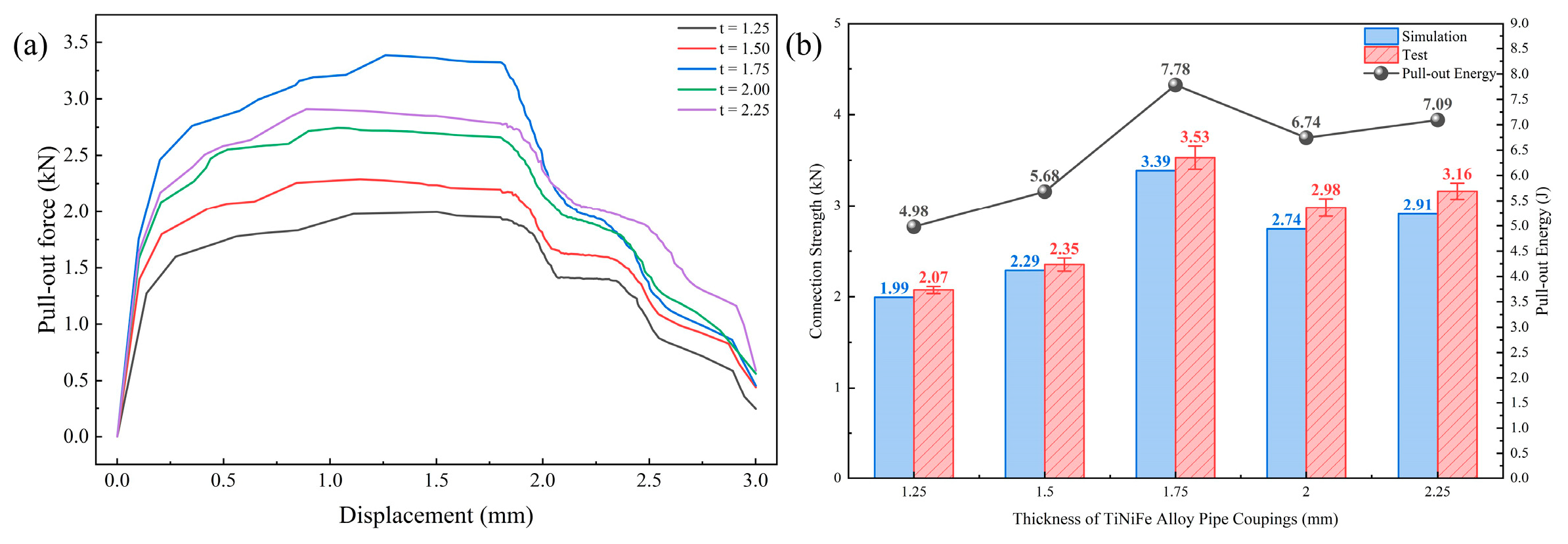
Figure 12 presents a comparative analysis of the effect of pipe coupling wall thickness on the connection performance. As the wall thickness increases, the contact stress on the mating surface exhibits a trend of first increasing and then decreasing. Consequently, the maximum recovery load that the assembled connection can sustain after fastening shows a similar variation. It should be noted that the connection strength of the TiNiFe pipe coupling depends not only on the contact stress at the interface but also on the tangential deformation of the tubes during the pull-out process. Taking the force–displacement curve under t = 1.75 mm as an example (Figure 11a), the pull-out process can be divided into three stages:
Initial stage (0–0.1 mm): The pull-out force rapidly increases to overcome the maximum static friction, inducing initial tangential deformation of the tubes.
Intermediate stage (0.1–2 mm): The tubes gradually deform tangentially under the action of the inner convexes, the radial displacement differences Δh decrease continuously, and the rate of increase in the pull-out force gradually slows down.
Final stage (>2 mm): As the tubes progressively disengage from the pipe coupling, the contact area diminishes, and the pull-out load decreases until complete connection failure occurs. These results indicate that both the radial contact stress and the tangential deformation behavior critically influence the connection strength, and optimizing the wall thickness is essential to achieve reliable fastening performance.
Figure 12b shows the variation in connection strength and pull-out energy under different wall thicknesses. The connection strength reaches a maximum of 3.39 kN at t = 1.75 mm, corresponding to the optimal fastening condition. Under a pull-out displacement of 3 mm, the pull-out energy increases from 4.98 J (t = 1.25 mm) to 7.78 J (t = 1.75 mm). When the wall thickness is further increased to 2.25 mm, the pull-out energy slightly decreases to 7.09 J. The numerical predictions are in good agreement with the experimental measurements in terms of both trend and peak values. The relative error between simulation and experiment is within 10%, demonstrating the reliability of the proposed finite element model under different geometric configurations. These results indicate that a moderate increase in wall thickness effectively enhances the connection performance, whereas excessive wall thickness provides limited additional improvement in connection reliability.

5. Conclusions

In this study, the radial recovery stress at different positions within the TiNiFe pipe coupling was determined using an inverse finite element method, and these stresses were applied as boundary conditions to develop a numerical model simulating the fastening and pull-out behavior of the TiNiFe pipe coupling with TA18 tubes. The connection state and pull-out failure under different wall thicknesses were systematically analyzed. The main conclusions are summarized as follows:
(1) Effect of wall thickness on fastening performance: The wall thickness of the pipe coupling has a significant influence on the connection performance. For 1.25 mm < t < 1.75 mm, increasing the wall thickness raises the maximum contact stress on the mating surface from 320 MPa to 750 MPa, thereby enhancing the fastening performance. When t > 1.75 mm, a further increase in the wall thickness leads to significant radial deformation in the inner convexes, which dominates the reduction in contact stress, resulting in an overall decrease in the maximum contact stress.
(2) Stages of pull-out failure: The pull-out process of the assembled connection can be divided into three stages. In the initial stage, the pull-out force rapidly increases, and the tube begins to slide, producing tangential deformation after overcoming the maximum static friction. In the intermediate stage, as the tube gradually disengages, tangential deformation progresses, and the rate of increase in pull-out force slows. In the final stage, as the contact area between the tube and the TiNiFe pipe coupling diminishes, the pull-out force gradually decreases until complete connection failure occurs.
(3) Critical wall thickness and design implications: A wall thickness of approximately 1.75 mm represents a critical value for optimizing the fastening performance of the TiNiFe pipe coupling. Controlling the wall thickness within this range ensures high contact stress while avoiding excessive local deformation, thereby improving connection reliability. The findings of this study provide guidance for the structural design and engineering application of TiNiFe shape memory alloy pipe couplings.

Author Contributions

All authors contributed to the study conception and design. Conceptualization, H.X., Z.Z. and S.H.; methodology, Y.L. (Yunbo Li); formal analysis, Y.L. (Yunbo Li) and Y.L. (Yanfeng Li); resources, W.Y., Y.Y., Y.L. (Yumeng Luo) and S.H.; writing—original draft preparation, Y.L. (Yunbo Li); writing—review and editing, Y.L. (Yunbo Li), X.S. and Y.L. (Yanfeng Li). All authors have read and agreed to the published version of the manuscript.

Funding

This research received no external funding.

Data Availability Statement

The original contributions presented in this study are included in the article. Further inquiries can be directed to the corresponding author.

Conflicts of Interest

Authors Yunbo Li, Haofeng Xie, Yanfeng Li, Xiaoyun Song, Wenjun Ye, Yang Yu and Yumeng Luo were employed by China GRINM Group Co., Ltd. Author Songxiao Hui was employed by GRIMAT Engineering Institute Co., Ltd. The remaining author declares that the research was conducted in the absence of any commercial or financial relationships that could be construed as a potential conflict of interest.

References

  1. Otsuka, K.; Ren, X. Physical metallurgy of Ti–Ni-based shape memory alloys. Prog. Mater. Sci. 2005, 50, 511–678. [Google Scholar] [CrossRef] [Scilit]
  2. Otsuka, K.; Wayman, C.M. Shape Memory Materials; Cambridge University Press: Cambridge, UK, 1998. [Google Scholar]
  3. Lagoudas, D.C. Shape Memory Alloys: Modeling and Engineering Applications; Springer: New York, NY, USA, 2008. [Google Scholar]
  4. Nespoli, A.; Ninarello, D.; Fanciulli, C. A Review on Shape Memory Alloys with Martensitic Transition at Cryogenic Temperatures. Metals 2023, 13, 1311. [Google Scholar] [CrossRef] [Scilit]
  5. Niccoli, F.; Giovinco, V.; Garion, C.; Maletta, C.; Chiggiato, P. NiTi shape memory alloy pipe couplers for ultra-high vacuum systems. Smart Mater. Struct. 2022, 31, 065014. [Google Scholar] [CrossRef] [Scilit]
  6. Xiao, J.F.; Cayron, C.; Van der Meer, M.; Logé, R.E. EBSD study of variant reorientation, texture, and twin formation in a martensitic NiTi alloy deformed in compression. Acta Mater. 2024, 264, 119553. [Google Scholar] [CrossRef] [Scilit]
  7. Waitz, T.; Antretter, T.; Fischer, F.D.; Karnthaler, H.P. Size effects on the martensitic phase transformation of NiTi nanograins. J. Mech. Phys. Solids 2007, 55, 419–444. [Google Scholar] [CrossRef] [Scilit]
  8. Wen, J.; Song, X.; Li, Y.; Liu, S.; Yu, Y.; Ye, W.; Hui, S. The effect of annealing treatment on the microstructure and texture of a cold-rolled TiNiFe shape memory alloy tube. Crystals 2024, 14, 274. [Google Scholar] [CrossRef] [Scilit]
  9. Azubuike, A.; Mysara, M.; Syahrir, R.; Victor, O. Advancing engineering frontiers with NiTi shape memory alloys: A multifaceted review of properties, fabrication, and application potentials. J. Alloys Compd. 2024, 976, 173227. [Google Scholar]
  10. Qu, L.; Yan, Z.-H.; Rao, Z.-X.; Wang, X.-Y.; Leng, J.-M.; Wan, W.-F.; Yan, X.-J. Review on the application of shape memory alloys in aerospace field. J. Aerosp. Power 2022, 37, 2127–2141. [Google Scholar]
  11. Matuszewski, L. Application of shape memory alloys in pipeline couplings for shipbuilding. Pol. Marit. Res. 2020, 27, 82–88. [Google Scholar] [CrossRef] [Scilit]
  12. Liu, J.; Ouyang, Z.; Lu, S.; Hou, J.; Huang, Y. Research basis of NiTi-based shape memory alloy pipe coupling. Appl. Mech. Mater. 2014, 687, 4351–4354. [Google Scholar] [CrossRef] [Scilit]
  13. Cao, B.; Iwamoto, T. A strength prediction of joints by Fe-Mn-Si-Cr shape memory alloy through strain monitoring during pre-processes including diameter expansion and tightening by heating. Eng. Fract. Mech. 2023, 284, 109234. [Google Scholar] [CrossRef] [Scilit]
  14. Cao, B.; Sun, Q.; Iwamoto, T. Bending fracture strength of the pipe joint using iron-based shape memory alloy (Fe-SMA) subjected to different expansion methods at various deformation rates. Eng. Struct. 2022, 267, 114669. [Google Scholar] [CrossRef] [Scilit]
  15. Machado, L.G.; Savi, M.A. Medical applications of shape memory alloys. Braz. J. Med. Biol. Res. 2003, 36, 683–691. [Google Scholar] [CrossRef] [Scilit]
  16. Song, G.; Ma, N.; Li, H.-N. Applications of shape memory alloys in civil structures. Eng. Struct. 2006, 28, 1266–1274. [Google Scholar] [CrossRef] [Scilit]
  17. Auricchio, F.; Petrini, L. Improvements and algorithmical considerations on a recent three-dimensional model describing stress-induced solid phase transformations. Int. J. Numer. Methods Eng. 2002, 55, 1255–1284. [Google Scholar] [CrossRef] [Scilit]
  18. Auricchio, F.; Taylor, R.L.; Lubliner, J. Shape-memory alloys: Macromodelling and numerical simulations of the superelastic behavior. Comput. Methods Appl. Mech. Eng. 1997, 146, 281–312. [Google Scholar] [CrossRef] [Scilit]
  19. Zhang, H.-B.; Jin, W.; Yang, R. 3D finite element simulation of pull-out force of TiNiFe shape memory pipe coupling with inner convex. Acta Metall. Sin. 2012, 48, 1520–1524. [Google Scholar] [CrossRef] [Scilit]
  20. Wei, Z.-X.; Zhang, W.-T.; Huang, Q.-D.; Wang, W.-W.; Xue, Y.-J. Experimental study and a modified model for temperature-recovery stress of shape memory alloy wire under different temperatures. Struct. Durab. Health Monit. 2025, 19, 347–364. [Google Scholar] [CrossRef] [Scilit]
  21. Lagoudas, D.C.; Entchev, P.B.; Popov, P.; Patoor, E.; Brinson, L.C.; Gao, X. Shape memory alloys, Part II: Modeling of polycrystals. Mech. Mater. 2006, 38, 430–462. [Google Scholar] [CrossRef] [Scilit]
  22. Panico, M.; Brinson, L.C. A three-dimensional phenomenological model for martensite reorientation in shape memory alloys. J. Mech. Phys. Solids 2007, 55, 2491–2511. [Google Scholar] [CrossRef] [Scilit]
  23. Li, Y.B.; Xie, H.F.; Zhang, Z.H.; Hui, S.X.; Li, Y.F.; Song, X.Y.; Ye, W.J.; Yu, Y.; Luo, Y.M. Numerical simulation of expansion deformation of the TiNiFe shape memory alloy ring. Adv. Eng. Mater. 2025, 27, 2403009. [Google Scholar] [CrossRef] [Scilit]
Figure 1. Tensile stress–strain curves of TiNiFe alloy under different conditions.
Metals 16 00427 g001
Figure 2. Schematic diagram of the structural dimensions of the TiNiFe alloy pipe coupling.
Metals 16 00427 g002
Figure 3. Tensile stress–strain curve of TA18 alloy tube.
Metals 16 00427 g003
Figure 4. Schematic of the connecting assembly.
Metals 16 00427 g004
Figure 5. Schematic of the connection strength test setup.
Metals 16 00427 g005
Figure 6. Schematic illustration of the loads, boundary conditions, and mesh configuration for each analysis step in the simulation model: (a) load and boundary condition settings; (b) local mesh refinement; (c) validation of the simulation model.
Metals 16 00427 g006
Figure 7. Flowchart of the finite element inverse method for determining the radial recovery stress.
Metals 16 00427 g007
Figure 8. Contact stress distribution between the pull-out end pipe and TiNiFe alloy pipe couplings with varying thicknesses upon completion of tight connections: (a) t = 1.25 mm; (b) t = 1.50 mm; (c) t = 1.75 mm; (d) t = 2.00 mm; (e) t = 2.25 mm; (f) schematic diagram of the assembly after fastening.
Metals 16 00427 g008
Figure 9. Contact stress distribution on the contact surface of the pull-out end tube after fastening: (a) distribution of contact stress along the axial direction; (b) variation in maximum contact stress, average contact stress, and contact zone length with pipe coupling thickness.
Metals 16 00427 g009
Figure 10. Radial strain variation after completion of the fastening connection with different TiNiFe pipe coupling thicknesses: (a) t = 1.25 mm; (b) t = 1.50 mm; (c) t = 1.75 mm; (d) t = 2.00 mm; (e) t = 2.25 mm; (f) variation trend of radial strain at the inner ridge.
Metals 16 00427 g010
Figure 11. Radial displacement distribution on the contact surface of the pull-out end tube after fastening: (a) radial displacement distribution along the axial distance; (b) bar chart of Δh as a function of wall thickness.
Metals 16 00427 g011
Figure 12. Variation in coupling strength of TiNiFe alloy pipe couplings with different wall thicknesses: (a) pull-out force–displacement curves; (b) variation in coupling strength and pull-out energy with wall thickness.
Metals 16 00427 g012
Table 1. The chemical composition of TiNiFe alloys.
ElementTiNiFeCNO
Content (wt. %)Bal.52.383.360.016<0.00390.024
Table 2. Structural dimensions of the TiNiFe alloy pipe coupling.
SpecimenLength L/mmThickness t/mmInner Convex Depth ICd/mm
1201.250.15
21.50
31.75
42.00
52.25
Table 3. Material parameters required for the UMAT subroutine of the TiNiFe alloy constitutive model (reprinted from Ref. [23]).
PropertiesResults
Critical transformation start stress σs-cr/finishing stress σf-cr99 MPa/167 MPa
A ↔ M transformation band slope CM/CA3.1/3.1
The maximum uniaxial transformation strain εtr-max (%)7.2%
Young’s modulus of austenite EA/martensite EM83 GPa/37 GPa
Poisson ratio of austenite/martensite0.33/0.33
A to M transformation temperature Mf~Ms−190~−170 °C
M to A transformation temperature As~Af−100~−60 °C
Coefficient of thermal expansion for austenite αA/martensite αM1 × 10−5/1 × 10−5
Yield stress of martensite σy-M/austenite σy-A750/500 MPa
Table 4. Radial recovery stress boundary conditions.
Thickness/mmInner-Convex Radial Recovery Stress σtr1/MPaInner-Wall Radial Recovery Stress σtr2/MPa
1.25340125
1.50380140
1.75415155
2.00445165
2.25475175
Disclaimer/Publisher’s Note: The statements, opinions and data contained in all publications are solely those of the individual author(s) and contributor(s) and not of MDPI and/or the editor(s). MDPI and/or the editor(s) disclaim responsibility for any injury to people or property resulting from any ideas, methods, instructions or products referred to in the content.