Review

Coatings for Hydro Turbine Applications: A Materials Perspective

Thermal Spray Centre (CPT), Universitat de Barcelona, Carrer de Martí i Franquès 1, 08028 Barcelona, Spain
*
Author to whom correspondence should be addressed.
Metals 2026, 16(4), 406; https://doi.org/10.3390/met16040406
Submission received: 25 February 2026 / Revised: 31 March 2026 / Accepted: 3 April 2026 / Published: 7 April 2026
(This article belongs to the Special Issue Surface Treatments and Coating of Metallic Materials (2nd Edition))

Abstract

Corrosion- and wear-resistant coatings are widely applied to hydro-turbine runners through thermal spray and cladding processes to enhance component efficiency and structural integrity by mitigating material loss during operation. This work provides a critical review of both mature and emerging coating materials, with particular emphasis on cermets, Fe-based amorphous alloys, high-entropy alloys, and functionally graded coatings. Their performance is analyzed in terms of wear, corrosion resistance, and applicability under hydro-turbine service conditions, highlighting the advantages and current limitations that hinder broader industrial adoption. The review identifies key challenges associated with materials chemistry, deposition processes, coating architecture, and cost-effectiveness, emphasizing the need for further advancements to improve coating reliability and competitiveness. In addition, a shift in coating design philosophy is proposed, moving toward a performance-driven and application-oriented approach in which coating properties are tailored to meet specific service demands through optimized material selection and process control. By integrating current knowledge and identifying critical gaps in the literature, this work provides a framework to guide future research efforts aimed at developing next-generation coatings for hydro-turbine applications.

1. Introduction

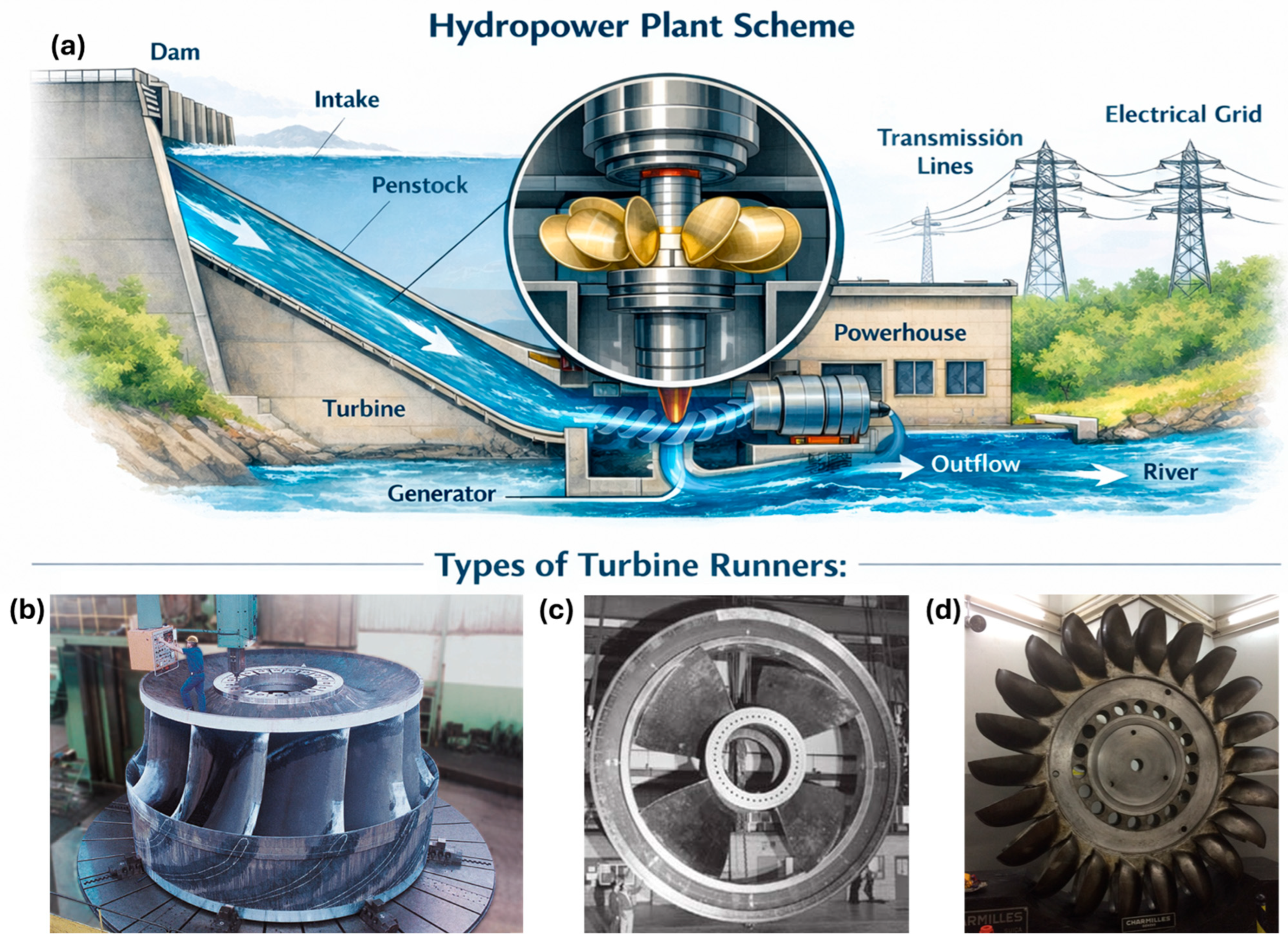
Hydropower, or water power, plays a pivotal role in global energy systems, serving as a cornerstone for renewable electricity generation in both developed and emerging economies, generating ~16% of electricity in the world [1]. The main elements of a hydropower station are presented in Figure 1a. Among them, the hydro-turbine runner has been the focus of much research because of its vital importance for powerplant operation. Improving the hydro-turbine runner lifespan or efficiency has been a challenge for the runners’ designers and maintenance engineering teams [2]. There are different runner types, as the most commonly seen are [3] Francis, Figure 1b—a large runner made by Voith Siemens company; Kaplan, Figure 1c—Annapolis Tidal Station, Canada [4]; and Pelton, Figure 1d—Governador Pedro Viriato Parigot de Souza Station, Brazil [5]. Runner selection depends on powerplant and river characteristics, like water flow head, among others [6].
Historically, hydro-turbine runners had been made of carbon steel or cast iron; however, since the 1960s, martensitic-austenitic or martensitic-ferritic stainless steels have been employed due to their higher strength and fatigue life. The most relevant material is ASTM A743 CA6NM [7], simply CA6NM henceforth. Casting and cast-welding have been the most-used techniques to build runners; however, recently, many manufacturers have used CNC-machined runners to avoid microstructural deleterious effects seen in casting and welding procedures [8]. Furthermore, CNC results in tighter tolerance machining, ensuring precision and improving the hydro-turbine efficiency [9]. More recently, additive manufacturing (AM) technologies have been employed to build small or pico-sized runners, e.g., a small Pelton runner built by laser powder bed fusion (L-PBF) [10] or prototyped by material extrusion (MEX) [11], or repairing damaged volumes by wire arc additive manufacturing (WAAM) [5,12,13]. It is important to note that AM use requires some caution because it can result in weaker mechanical properties, especially fatigue life, due to defects that are not seen in cast or wrought material [14].
Meanwhile, some failure phenomena seen in hydro-turbine runners are related to surface characteristics instead of strength or bulk properties. On this subject, surface engineering groups have employed much effort to identify the failure mechanisms, highlighting corrosion and wear behaviors, as well as developing new manufacturing techniques, new materials, or alternative strategies to mitigate deleterious effects intrinsic to powerplant operation. This work presents, with criticism, state-of-the-art tribology, coating materials, and coating deposition processes in use by industry and trends in materials for wear-resistant coatings in development. This work helps researchers to conduct their studies in new directions, bringing novelty to their work, and supports the industry in applying consolidated or new materials to solve real problems faced by the hydropower sector.

2. Data Mining Methodology

As a review-type work, the data mining strategy was limited to scientific articles published in indexed journals, doctoral theses, book chapters, standards, and conference proceedings. Most of the works were written in English for easier diffusion and access to the scholar. Furthermore, some technical reports were consulted due to their technical and industrial data contribution. No region was excluded since hydropower has been used worldwide, and researchers worldwide have studied this subject. The main tools for searching were the Google Scholar and Scopus websites, as well as Universitat de Barcelona’s library and Universitat Politècnica de Catalunya’s library for physical textbooks.
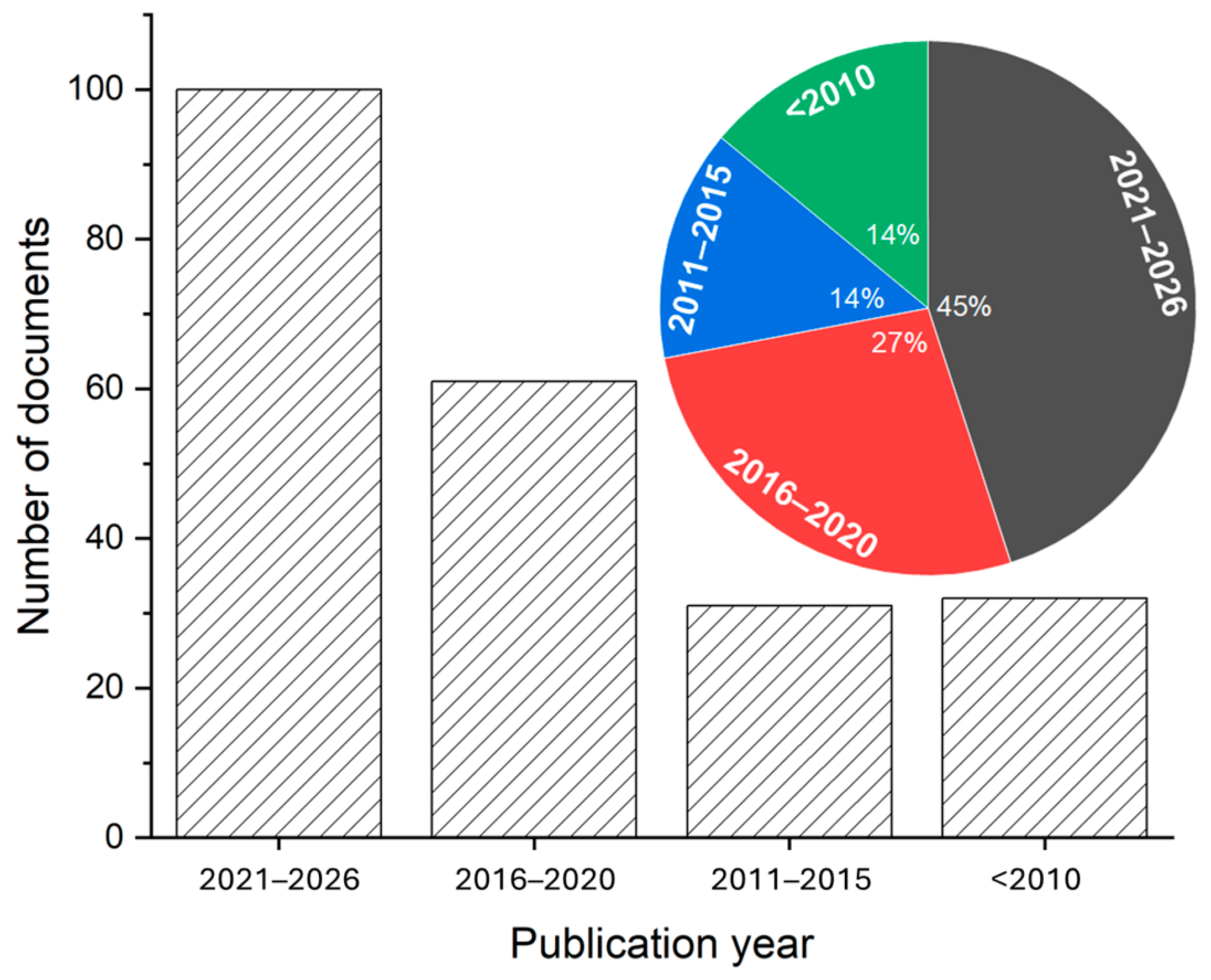
The time frame depended on the subject, i.e., for basic concepts, no age limit was established, and the most prestigious papers were considered; however, for the most recent advances in wear-resistant materials, no documents older than 10 years were accepted, guaranteeing state-of-the-art. However, to describe the evolution of some material families, a few old documents were considered as evidence of their evolution with the research efforts and over time. The query string contained mainly the keywords: “hydro-turbine”, “runner”; “wear”; “corrosion”; “coating *”; “thermal spray *”; “HVOF”; “electric arc”; CA6NM”; “fatigue”; “slurry”; “high entropy alloy”; “HEA”; “Fe-based”; “cold spray *”; “cladding”; “plasma transferred arc”; “laser”; “silt”; “cavitation”; “heat treatment” in the title or abstract section. The criteria for accepting and considering a document were related to hydro-turbine operation, fabrication, or maintenance; described the material performance; and introduced a concept or mechanism’s fundamental description or assigned it to possible use in hydro-turbines—as interpreted by the authors of this review work. The distribution of the 214 documents selected to compose this work with their publication year is presented in Figure 2.

3. Typical Damages

In the tribology field, the mechanisms that damage hydro-turbine runners have been studied individually, i.e., to make it possible to understand and model a wear mechanism, the test isolated it from other wear modes. With this objective, the test standards and methods have been written and followed worldwide systematically. The following concepts were drawn by a scholar with this background; however, the authors of this review work express their concern about interpreting these mechanisms, neglecting the synergism between them. Some researchers have published works exploring synergic phenomena, e.g., corrosion-cavitation or corrosion-erosion, but they still need more data regarding materials tested and media characteristics and properties, among other variables, to fill gaps in the literature. A good example of using a synergistic test is using the proper river water instead of a standard solution to predict the in situ material performance, such as using Iguaçu River water to test the potentiodynamic behavior of Fe-based coatings before their deposition on Francis-type runner blades of Governador Bento Munhoz da Rocha Netto Station [15].

3.1. Wear

Hydro-turbine runners are subjected to aggressive operating conditions that lead to multiple degradation mechanisms: (i) cavitation, (ii) erosion, (iii) fatigue cracking, and (iv) corrosion. Understanding and mitigating these damage mechanisms is crucial for enhancing the operational reliability and service life of hydro-turbine runners. This has challenged hydro-turbine designers in every new project to use the most recent and advanced techniques, e.g., finite element analysis (FEA), to preview the water flow and minimize the wear phenomena.
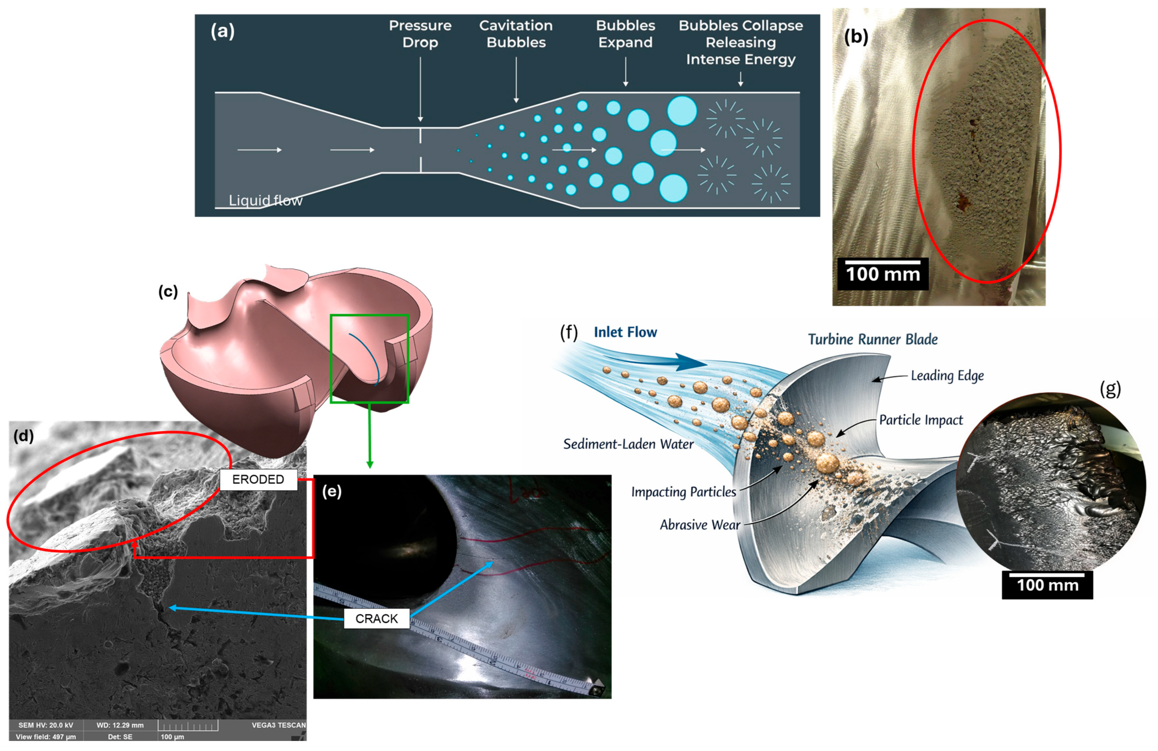
Cavitation is the formation, growth, and implosive collapse of vapor cavities in a liquid when local pressures fall below the vapor pressure, Figure 3a [16,17]; in hydro-turbines, this process generates pressure pulses, noise, unsteady loads, and surface damage on runner blades and other wetted components [18]. The primary causes of cavitation in runners are (i) adverse pressure gradients caused by off-design operation (partial load, high swirl, transient start/stop), (ii) local flow separation and vortex cores, and (iii) interaction with sediment or dissolved gases that alter nucleation thresholds [19]. Transients and load changes concentrate damaging cavitation cycles, while blade geometry and inflow conditions determine whether sheet or cloud cavitation will occur. Numerical and experimental studies link operating head, vane position, and inflow quality to cavitation inception and extent [19,20]. Cavitation damage, Figure 3b—Francis-type runner of Governador Bento Munhoz da Rocha Netto Station, Brazil—requires repairing and depositing cavitation-resistant materials, which has been a technical solution implemented industrially.
Silt erosion, particularly under sediment-laden flows, refers to the wear of hydro-turbines caused by suspended particles (often quartz-rich) impacting their components, especially runner blades [21], Figure 3f. In mountainous river systems (e.g., the Himalayas), very high sediment concentrations during monsoons drive intense erosion that degrades hydro-turbine efficiency and shortens maintenance intervals [22]. The phenomenon depends on multiple interacting variables, including silt concentration, particle size and morphology, flow velocity, and material properties of the runner surfaces [23]. The Brazilian Madeira River also has much sediment [24], resulting in damage to and mass loss on the large Kaplan-type runners of Santo Antonio Station and Jirau Station, Figure 3g. The primary causes of silt erosion stem from high-speed impacts of angular, hard particles. For example, silt in several rivers is reported to consist of 70~98% quartz, with a Moh’s hardness of ~7 [25,26]. In hydro-turbine runners, this erosion primarily affects vulnerable elements like Pelton buckets and nozzles or Francis-type vanes, blades, or seal rings [27,28].
Fatigue in hydro-turbine runners denotes the nucleation and propagation of cracks under cyclic mechanical and fluid-induced loading [14], ultimately leading to loss of load-bearing capacity. Primary causes of fatigue include (i) Ovariable steady-state loading; (ii) transient events (start-ups/shutdowns); (iii) flow-induced vibrations; and (iv) service-induced surface damage [29]. Transients during start-up produce large numbers of damaging cycles concentrated in short timescales, and sediment/erosion increases local stresses and stress concentration factors, accelerating crack initiation [30,31]. Case studies show that sudden vibration increases often precede blade failures [32,33] and catastrophic damage to the powerplant, as seen in Sayano-Shushenskaya, Russia, in 2009 [34].
Fatigue cracks always nucleate on the surface of the component, where the stress is maximum, and the surface condition, i.e., roughness, has a drastic impact on this crack nucleation [35,36,37]. In this case, wear, corrosion, and cavitation pitting act as stress concentrators, reducing the fatigue life of hydro-turbine runners, as identified in an analysis of a cracked Pelton runner bucket, Figure 3c—Governador Pedro Viriato Parogit de Souza Station, Brazil. On the surface of a large crack, Figure 3d, some small cracks were seen growing from the eroded surface, as highlighted in Figure 3e.

3.2. Corrosion

Although hydro-turbine components, such as runner blades, guide vanes, and draft tubes, are commonly made of stainless steels, exposure to aqueous environments with dissolved O2 and aggressive ions promotes electrochemical reactions that degrade even passive layers over time, initiating localized attacks such as pitting corrosion that lead to small cavities on the surface and serve as stress concentrator crack nucleation sites under service loads [38,39,40].
The interplay between corrosion and wear damage can accelerate material loss beyond what would occur from pure wear alone—synergism, as localized corrosion pits deepen and coalesce, reducing load-bearing cross-sections and creating stress concentrators [41]. This corrosion–fatigue interaction has been investigated for key hydro-turbine runner materials such as CA6NM, revealing that corrosion processes under cyclic mechanical stress significantly influence crack initiation and propagation behavior [28,42]. The water characteristics, e.g., hardness and dissolved O2, can lead not only to uniform corrosion but also to localized phenomena such as crevice corrosion or stress corrosion cracking (SCC) under tensile load, particularly in crevices formed between welded joints or under deposits where differential aeration cells develop [24,43]. The cumulative effect of such localized corrosion can be severe: pits and micro-cracks act as preferential sites for further mechanical attack, significantly shortening inspection intervals and increasing maintenance costs [33].

4. Coating Deposition Techniques

For small components exposed to cavitation or wear mechanisms, surface heat treatment (HT) or thin films result in a good performance. A 3 μm-thick TiN layer deposited by physical vapor deposition (PVD) improved the friction wear resistance of X37CrMoV5-L steel by ten times [44]. A 12 μm-thick low-temperature plasma nitride layer increased the sliding-wear resistance of 420 martensitic stainless steel, reducing the wear depth from 2.15 to 1.63 μm [45]. A 1.50 μm-thick diamond-like carbon (DLC) layer deposited by an ion beam deposition system on AISI 316L stainless steel increased its cavitation incubation time [46]. However, these techniques are not available or applicable for large components, such as hydro-turbine runners. Furthermore, the wear mechanisms that load hydro-turbine runners are much more severe than the mechanisms seen for small components. In this context, other techniques—cladding and thermal spray—have been developed and used to deposit wear-resistant materials, as follows.

4.1. Thermal Spray

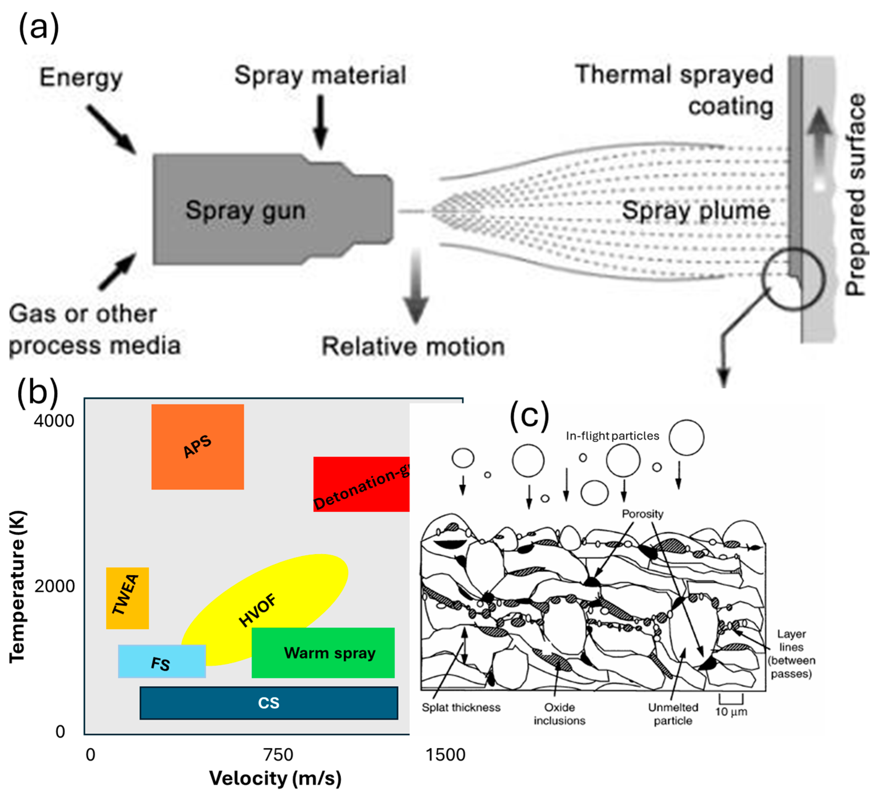
The thermal spray method comprises a group of manufacturing processes in which particles, Figure 4a—in molten, semi-molten, or solid-state condition—impact and bond onto a substrate, building a deposit that consolidates by (i) plastic deformation, (ii) Orapid cooling down, (iii) mechanical anchoring, and (iv) overlapping and interlocking, resulting in a coating composed by lamellae, oxides, unmolten particles, and pores, Figure 4c. Thermal spray produces coatings with thicknesses ranging from dozens of micrometers to millimeters in scale, reaching theoretically unlimited height for cold spray additive manufacturing (CSAM) [47,48,49]. Ceramics, polymers, metallic alloys and composite materials have been deposited by thermal spray, and selecting the thermal spray process depends on the temperature and velocity required for a material’s successful deposition [50,51,52]. Figure 4b shows a map of typical velocity and temperature ranges for the most used thermal spray processes.
Basically, thermal spray systems or equipment include (i)O feedstock supply systems (powder or wire feeding), (ii) gas/fuel sources, (iii) control units or consoles, (iv) guns, and (v) peripheral devices, such as robot arms, lathes, and air compressors [53]. The most industrially mature processes are (i) high-velocity oxy-fuel (HVOF), atmospheric plasma spraying (APS), twin-wire arc-spraying (TWEA), flame spray (FS), and a promising solid-state cold spray (CS) [54]. Depending on the material, process, and coating properties desired, different standoff distances and gun speeds can be chosen to control the deposit characteristics [52,55,56].
TWEA operates with two metallic wires fed to a gun that are molten by an electric arc formed between them. This molten material is atomized and dragged by a gas stream (compressed air is the most used) toward the substrate, where they flatten and rapidly solidify, depositing a coating. TWEA is widely used for corrosion- and wear-resistant metallic coatings such as Al-, Fe-, and Ni-based alloys, particularly in large-scale industrial components, due to its cost-effectiveness and portability [53,57].
FS is the oldest thermal spray process and is also used for corrosion-resistant coatings; however, the raw material (powder or wire) is fed—and molten—into a flame. The FS gun has the advantages of being small and light, ideal for in-field repairing services, and using cheap fuel: acetylene [53]. HVOF also uses a flame to melt the fed powder; however, its combustion under high pressure inside a chamber produces a supersonic gas jet, resulting in a higher velocity of particles and a more concentrated thermal plume. These HVOF flame characteristics achieve better coatings properties than FS and TWEA: e.g., HVOF NiCoCrAlY had 434 HV0.1, while this material deposited by FS had 277 HV0.1 [58]. HVOF has some variables, such as using gas or liquid fuel and using O2 or compressed air as an oxidizer (HVAF).
Figure 4. Thermal spray (a) scheme, (b) classification in according to particle velocity and flame temperature, adapted from [59], and (c) typical coating microstructure.
Metals 16 00406 g004
Table 1. Main thermal spray process summary.
ProcessHVOFTWEAAPSCSFS
Energy sourcecombustionelectric arcplasma jethot gascombustion
Strengths↓ oxidation
↑ adhesion
portability
↑ deposit rate
↑↑ temperature↓↓ oxidation
↑ adhesion
portability
Weakness↑ costs↓ density
↑ oxidation
↑ oxidation
↓ adhesion
↑ costs
ductile powder
↑ oxidation
↓ adhesion
ApplicationWC-Co, Cr3C2-NiCr, Ni-based, Fe-based, Co-basedFe-based, Zn-AlNiTi, NiAl, NiCrBSiCFe-based, Ni-based, Cr3C2-NiCr, WC-CoNi/TiO2/Al2O3
Reference[60,61,62][5,55,63][64,65][62,66,67][68]
APS uses a high-temperature plasma jet as an energy source to melt the powder, which is dragged by the gas of plasma to impact onto the substrate. APS reaches temperatures of thousands of Celsius, enabling the deposition of ceramics, in addition to metals and cermets, among others [64]. On the other hand, CS has principles based on accelerating a pressurized gas (N2, He, or compressed air) through a de Laval nozzle, dragging the feedstock powder onto a substrate [69]. The powder remains below the recrystallization temperature and reaches the substrate above a critical velocity [70], through which its severe plastic deformation drives the bonding mechanism, called adiabatic shear instability (ASI) [71,72]. Table 1 lists some characteristics and materials deposited by these techniques for hydro-turbine runner applications. Thermal spray techniques with higher temperature and/or lower velocity produce coatings with higher oxide content due to a longer exposure of the metallic phase to an oxidizing environment, highlighting the APS, TWEA, and FS processes. They also impact coating adhesion strength. However, a lower processing temperature and higher velocity of particles result in denser, more adhered and lower-oxide-content coatings. Furthermore, spraying O2-sensitive materials, e.g., Ti and Al alloys [49], also increases the oxidation of particles during the deposition.

4.2. Cladding

Notably, in addition to thermal spray, welding procedures are extensively use in industry to produce and repair worn hydro-turbine runners. Regarding the deposition of wear-resistant coatings, different cladding processes have been applied: gas metal arc welding (GMAW) to deposit Co-rich alloys and stainless steels [5,73,74,75], gas tungsten arc welding (GTAW) [76,77,78], laser cladding [79,80], shielded metal arc welding (SMAW) [81,82,83,84], and, more recently, plasma transferred arc welding (PAW) [85,86,87]. Controlling process parameters with advanced equipment, sensors and electronics has improved the deposition properties by obtaining a more refined microstructure in the weld metal and HAZ, e.g., GMAW with controlled short-circuit metal transfer mode—called cold metal transfer (CMT) [88], GTAW- [89], and PAW-pulsed arc [90]. Arc welding has some advantages: versatility to deposit many alloys, flexibility for manual, semi-automatic, and automated applications, and deposits with high-end properties, such as metallurgical bonding and high density. As disadvantages, high heat input causes HAZ microstructural changes, with intermetallic phases or low-toughness phases, e.g., δ-ferrite in CA6NM [91], tensile residual stress, distortion, and requirement of post-weld heat treatments (PWHT) for stress relief, among others [8,88,92].
A welding repair of a hydro-turbine runner involves nondestructive testing (NDT) to identify cracks and worn areas, removal of damaged material via gouging or machining, welding or cladding, and subsequent grinding and polishing [5,33,93]. Much of the existing research on welding of CA6NM runners focuses on controlling the weld microstructure to prevent the formation of deleterious phases such as δ-ferrite, excessive retained austenite, and brittle untampered martensite, all of which adversely affect toughness and fatigue life [91,94,95]. Although PWHT is recognized as an effective approach for microstructure recovery [96,97], its implementation is often impractical for the in situ repair of large-scale components. Alternative solutions, such as robotic induction PWHT, have been proposed to address this limitation [98].

5. Wear-Resistant Materials

The hydro-turbine runners must be available to operate and generate electricity for the longest period possible. Many countries are highly dependent on hydropower, and maintenance time must be as minimal as possible. For small stations, stopping for a few days for inspection and small repairs—including coating deposition—is practical; however, for large stations, the logistics for a runner repair require days or weeks. In this context, periodic maintenance has been scheduled for thousands of operation hours, reaching years for non-accessed runners. Most of this information is not published and is limited to companies’ internal reports. Furthermore, the best schedule for maintenance does not depend only on the runner integrity but also operational costs, season of the year, and energy price fluctuations, among other factors considered to stop a hydro-turbine for repairs [99,100,101,102]. Consequently, it is possible to understand that periodic inspections to evaluate new materials or experimental coatings are not a common practice in industry, and many laboratory tests must be performed before an in situ deposition procedure. In this scenario, a mature material, i.e., with known performance, is preferred for large runners. The literature presents the consolidated materials that have been systematically studied and, on large scale, deposited onto hydro runners to improve their performance. However, novel materials and possibilities have been explored and developed as alternatives to the traditional coatings.

5.1. Mature Applications

Fe-Cr-based alloys, like 17-4PH [80] and 410NiMo [103] martensitic stainless steels; Co-based alloys, like Stellite [73,84,104,105,106]; and Ni-based alloys, like NiCrBSi, are materials commonly deposited on hydro-turbine runners due to their known performance. An industrial example is a repair of a large carbon steel Francis-type runner of Governador Bento Munhoz da Rocha Netto Station, Brazil, which involved grinding the worn material, filling the volume with GMAW ER309L stainless steel, GMAW cladding with Co-rich Cavitalloy, and manual polishing [5]. However, for new runner manufacturing, and millimeter-scale volume repairs, thermal spray processes are preferred rather than welding.
In addition to metals, cermets have been widely deposited on hydro-turbine runners. Ceramic and carbide phases provide hardness and wear resistance, while a metallic binder bonds the hard grains and confers coating toughness. Under cavitation conditions, it is challenging to avoid hard grain spalling. HVOF cermets explicitly relate cavitation erosion behavior to microstructural integrity, such as low porosity, oxide content, and lamellae cohesion, as well as how flow conditions modulate film breakup and material removal [107,108,109]. The particle cohesion–cavitation performance relationship is evidenced by comparing an Fe-based coating deposited by HVOF [110]—higher cohesion—and CS [66]—lower cohesion.
Among the cermets, the most widely used are WC and Cr3C2 hard grains with a metallic binder (Co- or Ni-based) content of 7~25 wt.% [111,112,113,114]. The selection of binder chemistry and content depends on the deposition process chosen and application; e.g., CS requires a higher binder volume than APS since the latter has a bonding mechanism that relies on the particle plastic deformation, while the former inputs much more temperature to the powder, melting it [72,115,116]. WC-Co still outperforms Cr3C2-NiCr; however, for exposure to temperatures over 500 °C, the latter is stable, while for WC-Co coatings, the Co binder oxidizes, and WC grains decarburize [112], reducing the coating wear resistance. Researchers have studied new binders to avoid Co and Ni use, e.g., FeCrAl, also called green carbides [117,118]. Researching new and alternative binders for WC-cermets is an important subject for new commercial options in the industry since Co is widely recognized as a critical raw material by major economies, including the EU and USA [119,120,121].

5.2. Emerging Coating Materials

Emerging coating classes, advanced architectural concepts, and application-oriented performance criteria are being explored as complementary approaches to overcome the limitations of traditional methods and bridge the gap between laboratory-scale performance and the long-term behaviors of hydro-turbine runners in service.

5.2.1. Nanostructured Coatings

Nanostructured coatings have attracted considerable attention for hydro-turbine runner applications since they offer a potential route to improve hardness, thermally sprayed intersplat cohesion, and damage tolerance simultaneously, particularly in environments where silt erosion, cavitation, and corrosion-erosion interaction coexist [38,122]. In principle, nanoscale refinement can reduce the mean free path of the metallic binder, promote a more homogeneous distribution of reinforcing phases, and increase the density of interfaces that can deflect or arrest small cracks. These features are attractive for hydro-turbine runners, where surface degradation is rarely governed by single mechanisms and often evolves from repeated localized deformation, microcutting, and electrochemical attack acting together.
Experimental and analytical studies show that coating performance is strongly governed by parameters such as coating thickness, microstructural density, and phase distribution at the nanoscale, which together directly influence the ability of the surface to dissipate impact energy and resist electrochemical attack [123]. The fine size of the nanomaterials and the high density of the grain boundaries allow for excellent surface adhesion, although they can also create potential corrosion sites, as reported in the literature [124]. Additionally, it has been demonstrated that coating thickness directly influences microhardness, as studies of 300 μm-thick TWEA FeCrB coatings have shown a 15% higher hardness compared to the 550 μm-thick one [125]. These findings suggest that nanostructured coatings, when properly designed and deposited, can play a decisive role in extending the service life of hydro-turbine runners operating under severe erosive and corrosive conditions.
Among nanostructured systems, WC-based cermets remain the most studied. Their reported benefits are commonly linked to finer carbide dispersion, stronger load transfer from the metallic matrix to the hard phase, and reduced susceptibility to coarse carbide pull-out. Several studies report lower erosion rates for nanostructured WC-Co and WC-CoCr coatings than for conventional counterparts, and improved cavitation or wear behavior has also been observed in some cases [126,127]. However, the literature is not fully consistent. More recent comparative work shows that nanostructure alone does not guarantee superior performance since the final response depends strongly on whether the deposition route preserves the feedstock architecture or instead promotes decarburization, unmelted-particle defects, or insufficient fracture toughness [65,126,127,128,129,130].
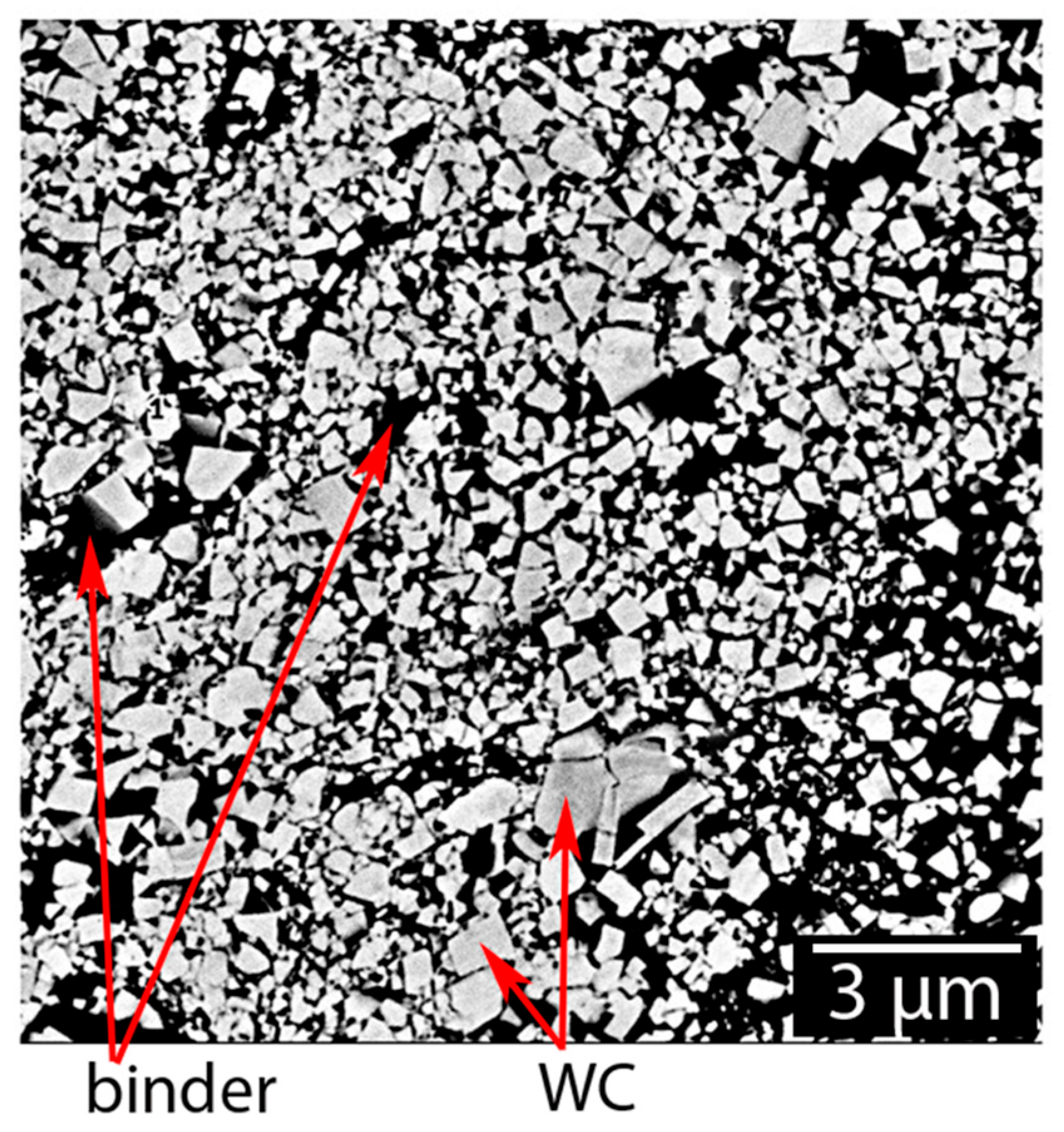
This point is particularly important when comparing HVOF and CS coating techniques. HVOF can generate dense nanostructured cermets with high hardness and good wear resistance; however, they also expose fine carbides to temperatures at which decarburization and phase transformation may become significant, especially if process optimization is insufficient [128,131,132]. By contrast, CS preserves the original carbide morphology much more effectively because bonding occurs below the melting point, which is advantageous for metastable or thermally sensitive feedstocks [67,69]. This effect is illustrated in Figure 5, where the angular WC morphology is largely retained in a CS WC-Co coating. Nevertheless, for hydro-turbine runner applications, phase preservation alone should not be interpreted as sufficient evidence of superior performance, since cavitation damage in sprayed coatings is often controlled not only by phase integrity but also by cohesion, porosity, and the quality of interparticle bonding [66,67,133]. A coating that preserves WC chemistry but contains weakly bonded or porous regions may still fail by progressive spallation under repeated bubble collapse. Consequently, the key issue when comparing HVOF and CS is not simply whether carbide degradation is minimized but whether the selected deposition route can produce a microstructure with a sufficiently robust balance of phase integrity, low porosity, and high interparticle cohesion [67,69,128,131,132]. Rounded carbide edges and the appearance of W2C, W, η, and γ phases are widely recognized signatures of decarburization in thermally sprayed WC-based coatings [115,131,132]. In this context, Figure 5 shows a morphology more consistent with limited carbide degradation, which is consistent with high decarburized APS WC-Co coatings that presented rounded carbide grains, as presented by Wayne and Sampath [116].
Beyond carbide-based systems, nanostructured ceramic- and oxide-based coatings have emerged as attractive alternatives for hydro-turbine applications, particularly in aqueous environments containing suspended solid particles, where both mechanical degradation and electrochemical attack operate simultaneously. The interest lies not only in their intrinsic hardness or chemical stability, but also in the microstructural advantages imparted by nanoscale refinement. In particular, nanostructured Al2O3 and Al2O3-TiO2 coatings have been reported to exhibit improved densification, refined splat morphology, and reduced interconnected porosity compared with conventional APS ceramics, leading to enhanced corrosion resistance and delayed material removal under erosion–corrosion conditions [134,135,136]. This refinement also promotes stronger inter-splat bonding and reduces preferential dissolution paths along splat boundaries, which are often responsible for accelerated degradation in conventional ceramic deposits [137,138]. In the same context, Al2O3-TiO2 nanostructured reinforcement in a Ni matrix deposited by a less expensive and portable FS process presented good erosion performance, highlighting its potential as a practical option for in-field fast runner repair [68]. Nevertheless, the relevance of these systems for hydro-turbine runners should be assessed critically. Although oxide- and ceramic-based nanostructured coatings may outperform carbide cermets in terms of chemical stability and corrosion resistance in aqueous media, their broader applicability can be constrained by lower tolerance to cyclic impact, limited thickness scalability, and insufficient mechanical compliance under cavitation-dominated or highly fluctuating hydraulic loading [134,139,140,141]. Consequently, their most convincing role is not yet a universal standalone solution for large hydro-turbine runner surfaces but rather as localized protective layers or as constituents of hybrid and multilayer architectures, where a hard nanostructured surface region is supported by a tougher and more compliant metallic underlayer. Such configurations may offer a more realistic balance between surface durability, adhesion integrity, and damage tolerance under the complex service conditions of hydro-turbine operation [141,142,143].
A second issue that deserves much stronger emphasis is industrial maturity. Although nanostructured coatings frequently show improved laboratory-scale erosion, cavitation, or corrosion performance [111,137], their broader adoption in hydro-turbine runners remains constrained by cost, feedstock manufacturing complexity, thickness limitations, and the limited availability of long-term field validation since many of the new materials are in level 1~3 in material maturity level (MML) [144], i.e., the materials exist, being more than a theoretical concept, but are still limited to laboratory validation. An MML 4—industrially validated—and MML 5—material fully accepted—are the next levels to be pursued by researchers This limitation is particularly relevant for hydro-turbine runner applications, where coating selection ultimately depends not only on laboratory-scale property improvements but also on reproducibility, repairability, and validation under long-term service conditions. In this context, a more meaningful research direction is to move beyond isolated improvements against a single reference substrate and to determine whether nanostructured coatings retain their advantages under service-representative combinations of sediment concentration, flow velocity, water chemistry, and cyclic repair conditions. Without such validation, nanostructured coatings remain scientifically promising but not yet fully qualified for broad industrial implementation in large hydro-turbine components [38,128,141,142].

5.2.2. High-Entropy Alloys

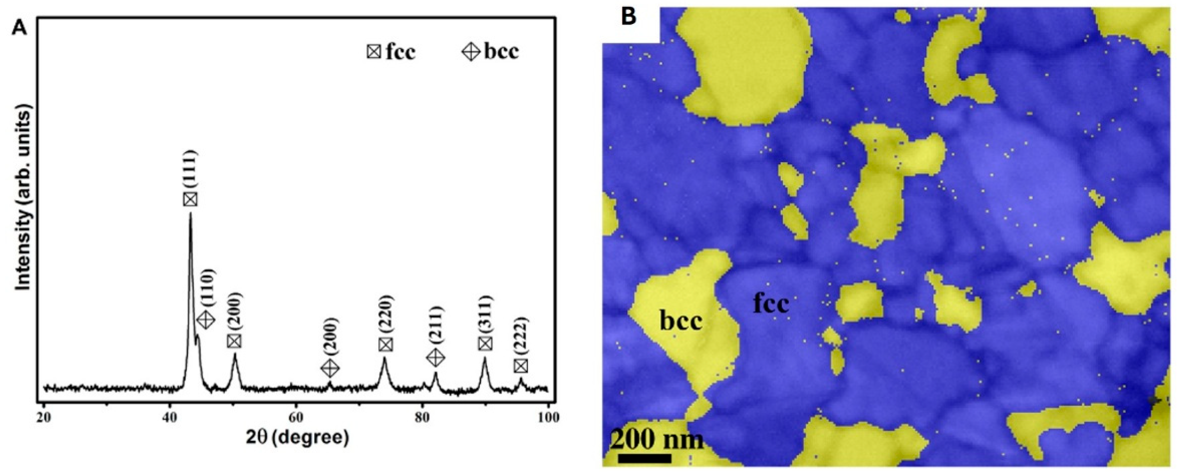
High-entropy alloy (HEA) coatings have emerged as a cutting-edge solution for many wear applications, with multiple studies highlighting their potential for hydro-turbine runners, particularly under severe erosion–corrosion and cavitation conditions [145,146]. Their appeal for hydropower applications lies in the possibility of combining, within a single coating system, several attributes that are difficult to achieve simultaneously in conventional materials, namely relatively high hardness, strain accommodation capacity, compositional tunability, and good corrosion resistance. In the context of hydro-turbine runners, this combination is especially attractive because service conditions do not reward hardness alone [147]. Cavitation requires tolerance to repeated high-strain-rate loading and resistance to crack initiation at defects, while erosion–corrosion synergy penalizes unstable passive films and microstructural heterogeneity. HEAs are therefore relevant not merely because they are compositionally novel, but because they offer a framework for tailoring multiple degradation-resistant mechanisms within the same coating system [148,149]. HEAs are composed of multiple principal elements, typically five or more in near-equiatomic proportions, which give rise to distinctive thermodynamic and microstructural characteristics, including a strong tendency toward the formation of simple solid-solution phases or a mix of them—often fcc or bcc, Figure 6B—rather than complex intermetallic compounds under appropriate compositional and processing conditions, Figure 6A [150,151]. Their performance is commonly attributed to four core effects: (i) high configurational entropy, (ii) severe lattice distortion, (iii) sluggish diffusion, and the so-called (iv) cocktail effect [152].
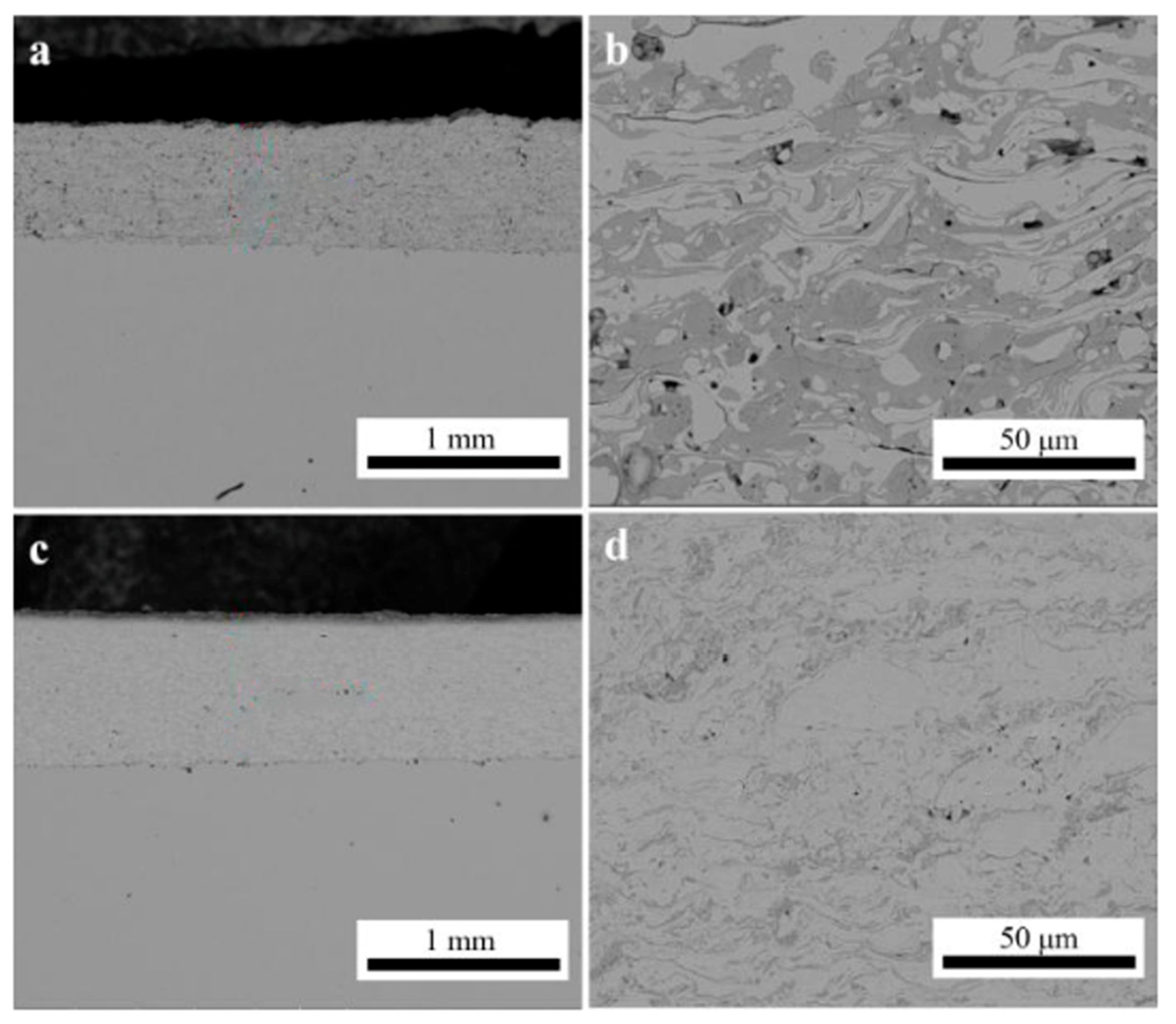
From a mechanical and tribological standpoint, HEA coatings have been reported to exhibit a favorable combination of high hardness and damage tolerance, together with an enhanced ability to accommodate plastic strain and resist microcutting and erosive wear mechanisms. Miracle demonstrated that the severe lattice distortion and complex solid–solution strengthening inherent to HEAs promote high resistance to plastic deformation while preserving fracture resistance, even under high-strain-rate or cyclic loading conditions [153]. Building on these mechanistic foundations, HVOF and APS FeCoCrNiMo0.2 coatings exhibited low porosity, a dominant lamellar microstructure, and distinct wear behaviors linked to their microstructural features, Figure 7, which correlate with enhanced resistance to microcutting and abrasive mechanisms [154]. In Figure 7, the coatings exhibit metallic, oxide, and porous phases (identified as light gray, dark gray, and black colors in Figure 7b, respectively). In addition, a reduced material removal rate in HEA coatings under erosive wear conditions was attributed to their combined hardness, work-hardening capability, and resistance to brittle fracture [155]. Taken together, these characteristics suggest that HEA coatings may be of interest for hydro-turbine runners, where coating systems are exposed to repeated solid particle impacts, cavitation-related stresses, and cyclic mechanical loading in aqueous environments [33,149,156].
Figure 6. Phase constitution of a representative HEA coating. (A) XRD pattern and (B) EBSD map of a CoCrFeNi coating showing the stabilization of simple fcc and bcc solid–solution phases. Reprinted from [157].
Metals 16 00406 g006
Figure 7. Cross-sectional SEM micrographs of (a,b) APS and (c,d) HVOF FeCoCrNiMo0.2 coatings. Reprinted from [154].
Metals 16 00406 g007
However, the literature on HEA coatings should be interpreted with caution. A recurrent limitation in this field is that many studies emphasize generic HEA concepts, such as high configurational entropy, sluggish diffusion, or severe lattice distortion, without clearly demonstrating how these features translate into coating-scale performance after deposition because the coating performance is microstructure-dependent and the processing techniques used result in different microstructures, with distinct phase distribution or chemistry, as seen in Figure 7 and described in the literature [147,158]. While these concepts may provide useful mechanistic guidance for bulk alloys, the final behavior of coatings is strongly mediated by processing-induced factors such as oxidation, porosity, residual stress, splat bonding, segregation, and secondary phase formation. Accordingly, a key scientific challenge is not simply to show that HEA coatings are hard or corrosion-resistant, but to establish composition–process–microstructure–property relationships that remain valid after thermal spray, laser cladding, or CS deposition [148,154,159,160,161].
Corrosion resistance represents another critical advantage of HEA coatings for hydro-turbine runner applications. Several studies have demonstrated that many HEA systems develop stable, compact, and adherent passive films, frequently enriched in Cr-, Al-, or Ti-based oxides, which result in significantly reduced corrosion current densities and enhanced passivation behaviors in simulated river water and chloride-containing environments [162,163,164]. In particular, Cr-containing HEAs promote the formation of chemically stable metallic oxide layers that effectively hinder ionic transport across the surface, leading to improved resistance against uniform and localized corrosion processes [162]. Complementary electrochemical investigations confirmed that Al- and Ti-rich HEA coatings exhibit improved passivity and delayed breakdown in aggressive aqueous media, attributed to the synergistic stabilization of mixed-oxide films [165,166,167]. These characteristics are especially relevant for hydro-turbine runners operating in sediment-rich waters, where corrosion-erosion synergy accelerates surface degradation. Additionally, the sluggish diffusion effect commonly associated with HEA has been reported to retard localized corrosion kinetics and suppress rapid compositional redistribution under service conditions, thereby contributing to the long-term electrochemical stability of HEA coatings in aqueous environments [158].
Nevertheless, a more critical perspective is also needed in the discussion of corrosion behavior. Passive-film stability alone does not necessarily ensure good service performance if the coating architecture contains interconnected porosity, poorly bonded splat boundaries, or galvanic heterogeneities introduced during deposition [168,169]. For hydro-turbine applications, corrosion resistance must therefore be discussed as a coating-system property rather than merely as an intrinsic alloy property [24]. This distinction is important because the apparent electrochemical advantage of a given HEA composition may be substantially reduced if deposition defects facilitate electrolyte ingress or create locally unstable passive-film conditions. From a tribological standpoint, HEA coatings are promising because they may help to bridge the classic trade-off between hardness and damage tolerance more effectively than many conventional metallic alloys and, potentially, some cermet systems. However, the literature still lacks sufficient direct comparisons against the true industrial benchmarks for hydro-turbine runners—WC- and Cr3C2- cermets [111,112,113,114], and established weld overlays [73,84]. This remains a crucial gap. Demonstrating that an HEA coating outperforms an uncoated stainless steel substrate is scientifically useful, but it is not sufficient to justify industrial adoption unless the same coating is compared under equivalent conditions with the systems already used in practice. Without that level of benchmarking, claims of superiority should still be regarded as preliminary.
The processing routes used to produce HEA raw material powders significantly impact the performance, cost, and scalability of the resulting coating. Gas atomization is one of the most widely used techniques for manufacturing HEA powders because it can generate spherical particles with controlled size distribution and homogeneous chemical composition [170]. These characteristics are essential for thermal spraying processes, such as HVOF and APS. However, atomizing multicomponent alloys often incurs high production costs due to high melting temperatures, the need for precise composition control, and material losses, particularly when refractory or high-purity elements are employed [171]. Conversely, mechanical alloying (MA) is a flexible, cost-effective solid-state method that enables the synthesis of metastable solid solutions and extended compositions, which can be challenging to achieve through equilibrium melting methods [171,172]. MA-derived HEA powders are attractive for research-scale development, especially for compositions containing elements with large differences in melting points. However, challenges related to contamination, particle morphology, and powder flowability remain. Other powder production methods, such as rotating plasma electrode processes and centrifugal atomization variants, are being explored to obtain high-quality, spherical powders with narrow size distributions and good flowability. These methods are promising for both AM and thermal spray feedstock [172,173]. From an industrial standpoint, the selection of the powder production route must consider not only metallurgical results but also cost, deposition efficiency, and lifecycle advantages compared to conventional coating systems.
From a processing perspective, the adaptability of HEA to advanced coating technologies such as HVOF, laser cladding, APS, and CS represents a major opportunity for their implementation in hydropower systems [148,159,160]. However, the processing route is not a secondary variable but a decisive part of the coating design itself. CS is attractive for preserving metastable solid-solution phases and minimizing elemental segregation or oxide formation [147,161], whereas laser cladding may offer stronger metallurgical bonding and, in some systems, superior cavitation-related performance. HVOF and APS, in turn, provide distinct combinations of porosity, oxide content, interlamellar cohesion, and residual stress. Thus, each route modifies not only the final microstructure but also the resulting failure mode and property balance. In practice, the “best HEA” cannot be separated from the “best HEA-processing route combination”. This point is well illustrated by the comparison shown in Figure 7, where APS- and HVOF-deposited FeCoCrNiMo0.2 coatings exhibit markedly different distributions of metallic regions, oxides, and porosity [154]. Figure 7, therefore, reinforces a critical point for hydro-turbine applications: coating performance cannot be inferred from nominal composition alone, because process-induced heterogeneity strongly affects both tribological and electrochemical response.
Despite their promising performance, the application of HEA coatings in hydro-turbine runners is still at an early stage of technological readiness, with an MML of 0~2 [144,174], because researchers are still developing and formulating new chemistries or are producing powder in laboratory scale [175]. Future research must focus on establishing clearer composition–microstructure–property relationships tailored to erosion–corrosion and cavitation environments relevant to hydropower [145]. More importantly, these relationships should be assessed through direct comparison with mature industrial reference systems and under service-relevant coupled degradation conditions. Long-term durability studies, including field validation under realistic operating conditions, remain necessary to assess the transferability of laboratory-scale results. Additionally, considerations of economic factors, such as raw material cost, powder production scalability, deposition efficiency, and repair strategies, are likely to play an important role in any future industrial implementation. At present, the main barrier to implementation is not the absence of promising results but the lack of evidence that HEA coatings offer a sufficiently robust and economically justified advantage over mature systems. Until such evidence becomes available, HEA coatings should be viewed as high-potential systems with strong scientific momentum, but not yet as established replacements for conventional cermets or weld overlays.

5.2.3. Fe-Based Amorphous Coatings

Fe-based amorphous or metallic glass coatings have emerged as a highly relevant class of materials, and their increasing prominence is primarily associated with their ability to address, within a single material system, erosion and corrosion resistances [176,177,178,179]. For hydro-turbine runner applications, this multifunctionality is particularly attractive because degradation rarely occurs through a single mechanism; instead, corrosion, silt erosion, and cavitation frequently interact, with electrochemical attack often weakening the near-surface region before subsequent mechanical damage by sediment impact or bubble collapse. From a microstructural perspective, the absence of long-range grain boundaries and the high chemical homogeneity inherent to amorphous phases promote a more uniform stress distribution under repeated particle impacts and cavitation loading, while also favoring the stability of Cr- and Mo-enriched passive films [180]. For instance, HVOF Fe-based amorphous coatings exhibited significantly lower erosion–corrosion rates than conventional stainless steels in sand-containing NaCl solutions, which was attributed to the formation of a stable and rapidly repassivating passive layer [181]. FeMnCrSi had been evaluated by different coating deposition techniques, evidencing that a similar chemical composition is dependent on the processing temperature and environment. Higher oxide content and lower cohesion of particles negatively impacted the cavitation performance [66,87,182].
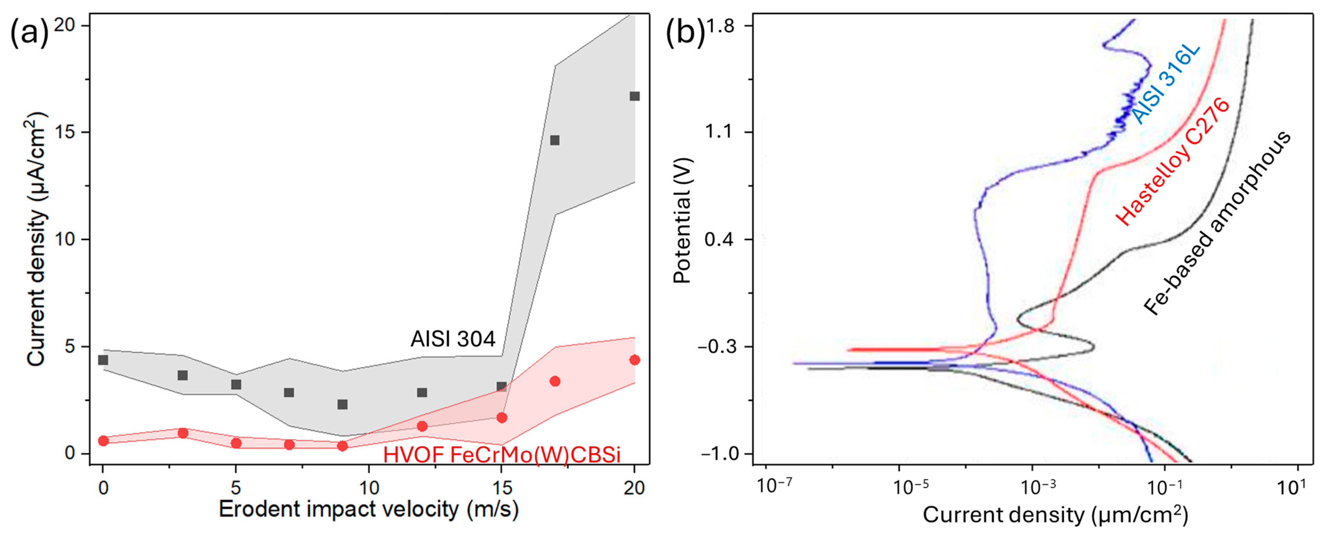
Similarly, such coatings display a higher critical flow velocity for passive film breakdown during silt impingement, evidencing improved resistance against mechanically assisted corrosion processes, Figure 8a [176]. This behavior is particularly relevant for hydro-turbine runners, where corrosion-assisted degradation can accelerate subsequent material removal under erosive or cavitating flow conditions. From a microstructural standpoint, the absence of crystalline defects such as grain boundaries and phase interfaces, combined with high chemical homogeneity, promotes more uniform stress distribution under repeated particle impacts and hydrodynamic loading. These features are also known to enhance the formation and stability of protective passive films, particularly those enriched in Cr and Mo [180]. Electrochemical studies consistently report that Fe-based amorphous coatings exhibit extended passivation regions and reduced corrosion kinetics compared with conventional crystalline alloys. For example, Fe-based amorphous films produced by radio-frequency magnetron sputtering display a broad and stable passivation domain even in highly aggressive acidic environments, which is attributed to the formation of dense Cr- and Mo-rich oxide layers, Figure 8b [177]. In this sense, Figure 8 not only illustrates improved electrochemical stability, but also supports the broader interpretation that the main advantage of Fe-based amorphous systems is especially pronounced in environments where corrosion-assisted damage plays a significant role.
The FeCrMo(W)CBSi family dominates reported studies owing to its high glass-forming ability and the corrosion resistance associated with Cr- and Mo-rich passive films in chloride-containing environments. HVOF produces dense and low-oxide coatings, which are critical for preserving a largely amorphous structure after deposition [178]. However, the literature increasingly shows that the performance of Fe-based amorphous coatings is controlled not only by the retained amorphous fraction itself but also by the overall quality of the deposited architecture. This distinction is critical, since a coating described as amorphous may still perform poorly if spraying induces excessive oxide formation, insufficient interlamellar bonding, partially molten particles, or localized crystallized defect-rich regions that act as preferential damage initiation sites [179]. Structural characterization consistently confirms this behavior.
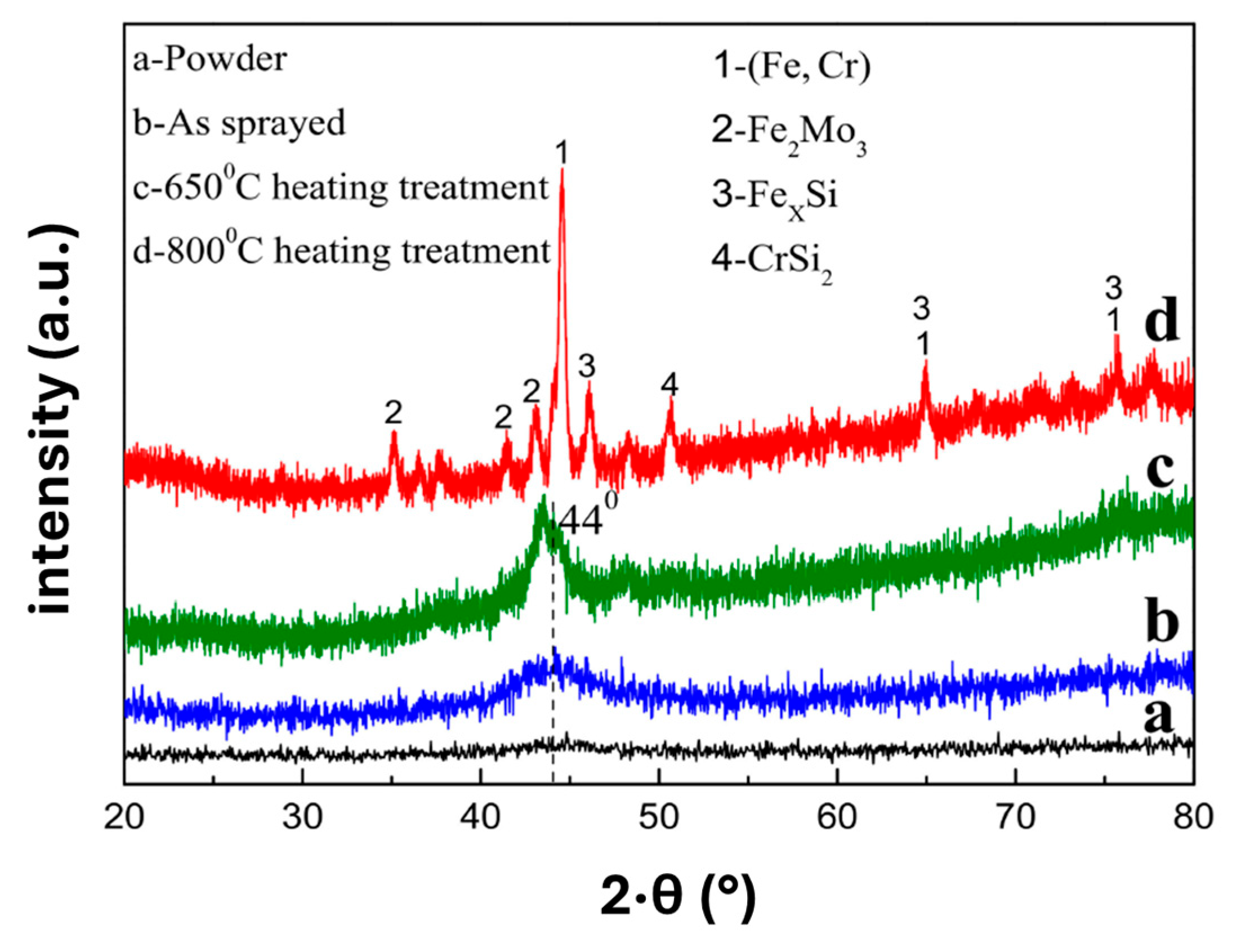
Representative XRD patterns typically exhibit broad diffuse maxima rather than sharp Bragg reflections, evidencing the dominant amorphous phase retained in the as-sprayed condition. HVOF Fe-based metallic glass coatings display characteristic amorphous halos, while crystallization occurs only upon exposure to sufficiently high temperatures during a post HT, highlighting the metastable yet structurally stable nature of these systems, Figure 9 [183]. Accordingly, Figure 9 is relevant not only as evidence of amorphicity but also because it highlights how retained amorphous structure depends on the combined effect of composition, thermal history, and spraying conditions.
Focusing on processing–microstructure relationships, HVOF FeCrMo coatings produced under optimized conditions can achieve long-term corrosion protection when appropriate sealing treatments are applied, maintaining barrier performance for more than 1500 h in cyclic corrosion testing. Furthermore, controlled devitrification markedly increases hardness, from approximately 780 HV in the as-sprayed state to values exceeding 1000 HV at high crystallinity, highlighting the strong coupling between phase evolution and mechanical performance [184]. Complementarily, minor Mo additions in FeCr-based metallic glass promote a higher retained amorphous fraction and suppress the formation of α-Fe during HVOF deposition, resulting in improved wear resistance and enhanced corrosion behavior. These improvements were attributed to the combined effects of increased amorphicity and the formation of a more protective and chemically stable Cr/Mo-enriched passive film, underscoring the critical role of compositional tuning in conjunction with process optimization [185]. Taken together, these findings suggest that maximizing hardness or the retained amorphous fraction alone should not be interpreted as a sufficient design criterion, because in-service performance in hydraulic environments also depends on passive film stability, coating cohesion, and damage tolerance [178,179,186,187].
Cavitation resistance represents a more critical and nuanced challenge for Fe-based amorphous coatings. Although these systems perform very well under conditions of erosion and corrosion, their advantages do not necessarily apply to all types of damage that hydro-turbine runners may sustain. Cavitation damage in HVOF Fe-based amorphous coatings is strongly influenced by spray parameters and microstructural integrity, with damage initiation frequently occurring at pores, oxide-rich regions, and partially molten particles due to low interlamellar cohesion [188,189]. This indicates that cavitation resistance is governed less by nominal amorphicity or hardness alone than by fracture toughness, crack-growth resistance, and local interface quality. Therefore, coatings with excellent corrosion behavior may still exhibit only modest cavitation performance if toughness and cohesive integrity are not simultaneously optimized. Nevertheless, incorporating toughening strategies, such as Ni-coated Al2O3 reinforcements, can significantly improve their fracture toughness and cavitation erosion resistance, underscoring the importance of toughness-driven design rather than hardness optimization alone [190]. However, this also makes raw powder more complex with an economic impact on feedstock production. More broadly, strategies such as controlled HT, sealing, remelting, or the addition of reinforcements should be assessed not only in terms of hardness gain but also in terms of their effect on crack initiation resistance, delamination tendency, and service-relevant durability.
Despite these promising attributes, several limitations and research gaps remain that constrain the industrial deployment of Fe-based amorphous coatings in hydro-turbine runners. Their performance is highly sensitive to processing conditions, which complicates the transferability of optimized parameter windows between different spraying systems. This sensitivity remains one of the major barriers to industrial qualification, because even when HVOF is broadly recognized as favorable for producing dense, low-oxide, highly amorphous deposits, relatively small differences in thermal input or particle state can alter defect population and, consequently, service behavior. From an application perspective, Fe-based amorphous coatings are nevertheless closer to industrial relevance than many other emerging families because their compositions are generally less dependent on critical or expensive alloying elements than Co-rich materials or some advanced HEA systems. Even so, most studies to date rely on laboratory-scale test rigs, and there is still a notable lack of long-term validation under real hydropower operating conditions involving natural sediments, fluctuating flow regimes, variable water chemistry, and repeated repair cycles. Thus, the most urgent need is not merely for additional laboratory evidence showing that these coatings can perform well under selected conditions, but rather for systematic validation of how retained amorphicity, post-treatment, interlamellar cohesion, and defect population affect durability under service-representative conditions. Addressing these challenges through microstructural design strategies aimed at enhancing interlamellar toughness, controlled post-processing, and component-scale validation will be essential to consolidate Fe-based amorphous coatings as a mature and reliable solution for hydro-turbine runner protection.

5.2.4. Advanced Coating Architecture

Beyond the development of new chemical compounds, the deliberate architectural design of coating systems that combine hardness-dominated responses with damage tolerance and interfacial integrity is a clear ‘future trend’ in hydro-turbine runner protection. More fundamentally, this trend reflects a progressive shift from viewing the coating as a single homogeneous material toward considering it as a through-thickness functional system, in which different regions are designed to fulfill different roles under service conditions [191,192]. An example of this concept is thermal barrier coatings for gas turbines, where a metallic MCrAlY bond coating deposited by APS or HVOF protects the substrate against corrosion and a ceramic YSZ top coat has the role of thermal barrier to protect the substrate from high-temperature environments [193]. This perspective is motivated by the fact that the dominant degradation modes in hydro-turbine runners impose partially conflicting demands. Cavitation erosion is characterized by cracks appearing at lamellae boundaries, pores, and oxide-rich layers, which leads to fatigue-induced delamination [17,19], whereas silt erosion is more strongly influenced by microcutting, ploughing, and the brittle removal of hard phases, depending on the impact angle and particle dynamics [23,26]. As a result, these degradation modes are difficult to optimize simultaneously within a single monolithic layer, suggesting that coating performance depends not only on chemistry but also on architecture and defect distribution, especially when multiple damage mechanisms act concurrently [114,191,192]. Early comparative tests showed that thermally sprayed coatings can significantly increase resistance to combined slurry and cavitation loads compared to uncoated hydro-turbine runners. This helped consolidate the view that performance depends not only on chemistry but also on architecture and the network of defects, especially when multiple degradation modes act simultaneously [114].
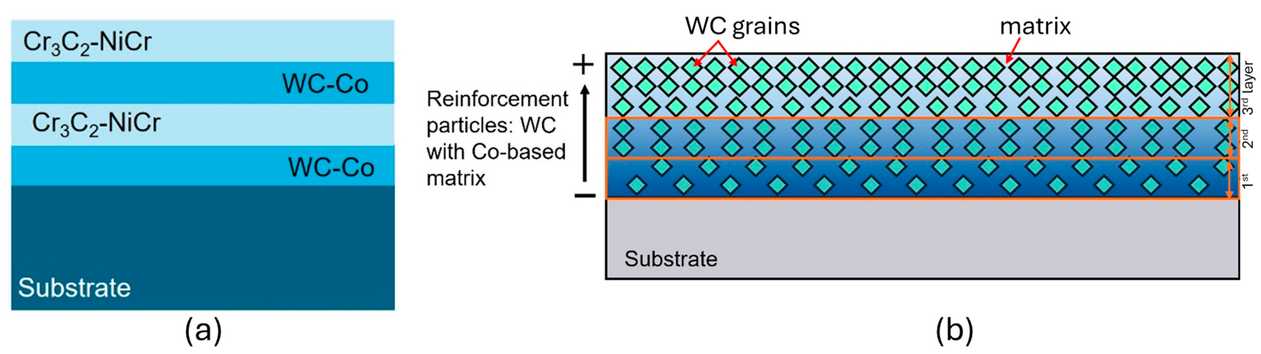
One architectural approach is to use a multilayer system composed of a hard, erosion-resistant top layer and a more resilient underlying layer. This bottom layer reduces stress concentration, accommodates cyclic deformation, and mitigates the propagation of interfacial cracks. In this sense, multilayer systems are attractive because they distribute functions across the coating thickness rather than forcing one layer to provide all properties simultaneously [116,127]. A hard outer layer may enhance resistance to sediment-driven abrasion, while an intermediate or bond-compatible layer can attenuate stress concentrations, improve adhesion, and delay crack propagation toward the substrate [186]. One example is sub-micrometer multilayer architectures of HVOF WC-Co/Cr3C2-NiCr, which were developed to take advantage of the different properties of WC- and Cr3C2-reinforced films in cavitation and corrosion environments [191]. Figure 10a illustrates the idea that layered designs can redistribute damage and slow delamination more effectively than single-layer designs. Studies focused on cavitation in thermally sprayed systems have revealed that cavitation durability is related to interlamellar cohesion and crack growth resistance rather than hardness alone. This reinforces the technical rationality of multilayer approaches designed around interfaces for channels exposed to cyclic bubble collapse loads [105].
Functionally graded coatings (FGC) extend this logic further by introducing a gradual variation in composition and/or reinforcement fraction through the coating thickness, Figure 10b, thereby avoiding sharp property discontinuities and helping to control residual stress distribution and material fracture behavior. Thermal spraying is particularly well-suited to FGC deposition because feedstock blending and process parameter modulation allow continuous gradients in reinforcement fraction, matrix composition, and even porosity level, enabling tailored through-thickness profiles in hardness, toughness, and corrosion response [186]. In hydro-turbine operation, where cyclic hydrodynamic loading and repetitive localized damage are common, this FGC is not merely a minor refinement; it directly affects whether damage remains confined to the near-surface region or evolves into delamination and large-area spallation [191,192,194,195]. Thermally sprayed FGC is most effective when it is used to mitigate the classic trade-off in cavitation and/or erosion applications: hard, stiff top layers resist microcutting but tend to crack and delaminate under cavitation-fatigue mechanisms, whereas tougher metallic layers better absorb impact energy but may erode rapidly under silt erosion [192]. The conceptual distinction between multilayer and FGC is summarized in Figure 10, which emphasizes how functional distribution through thickness may be used to decouple hardness and damage tolerance requirements. This coating morphology distribution can be achieved by changing the feedstock powder characteristics—hard grain size [116,196], particle size distribution [197], or chemistry [60]—deposition technique [115,116], or processing parameters [60], among other possibilities.
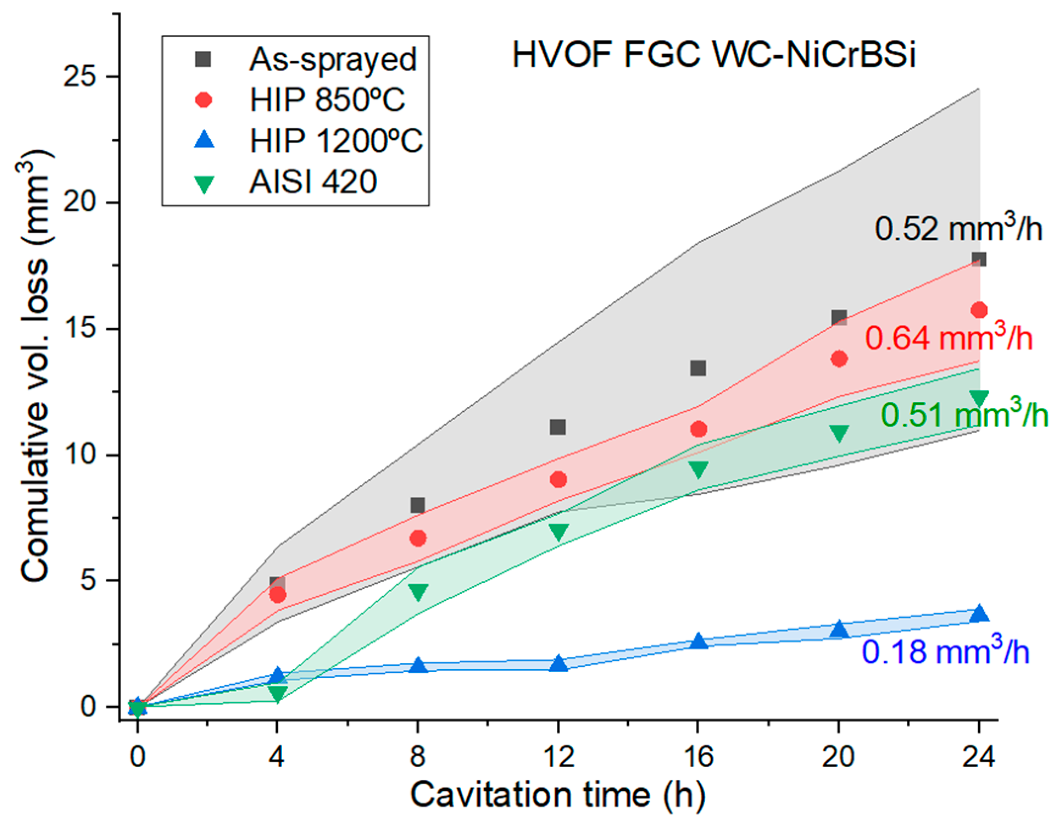
Recent studies provide useful coating-system evidence in support of architectural rationale, because they relate multilayer or graded design concepts to measurable cavitation-performance outcomes. For instance, HVOF FGC WC-NiCrBSi, combined with improved interlamellar bonding through hot isostatic pressing (HIP), showed substantially increased cavitation erosion resistance, suggesting that architectural design together with interface densification can strongly influence performance in addition to chemistry alone [194]. Figure 11 is particularly valuable because it translates the architectural concept into a service-relevant response, showing that the graded system clearly outperforms the AISI 420 stainless steel substrate under cavitation exposure. Similar strategies have also been explored for thermal barrier coatings, in which graded ceramic layers or optimized metallic bond coats are used to tailor through-thickness properties and interfacial behavior [195] or by optimizing a metallic bond coating deposition between a superalloy substrate and a ceramic top layer [198,199]. Taken together, these examples support the view that coating architecture can be as important as chemical composition when failure is strongly influenced by interfacial stresses and crack evolution.
At the same time, a critical reading of the literature shows that architectural concepts are presently discussed more convincingly at the conceptual level than at the level of quantitative design rules. Many studies report improved mass-loss behaviors for multilayer or graded systems, but only a limited number identify which architectural descriptors are most influential, such as layer thickness ratios, gradient slope, interfacial roughness, oxide-stringer density, residual-stress distribution, pore connectivity, or post-treatment sequence. As a result, advanced architecture is often presented as a promising trend rather than as a quantitatively engineered solution. Several cross-cutting research needs emerge across these architectural strategies (multilayer, graded, and hybrid composite systems) that are particularly relevant for hydro-turbine runners. First, a robust, quantitative design framework is needed to link architectural descriptors, such as gradient profile, layer thickness ratios, interfacial roughness, oxide-stringer density, and pore connectivity, to cavitation erosion life under hydro-turbine representative flow regimes. Most studies remain limited to laboratory rigs and have limited transferability across powerplants and sediment loads and service histories [200]. Second, since cavitation is often governed by interlamellar crack growth, architecture must be optimized for delamination fatigue. However, many datasets emphasize hardness and mass-loss curves without systematically measuring or reporting toughness-related metrics (e.g., fracture toughness surrogates, cohesive strength, or fatigue crack growth proxies) alongside cavitation erosion. Third, post-processing routes (HT [201], sealing [202], HIP [69], and remelting [203]) are increasingly used to strengthen lamellar interfaces. However, there is still insufficient clarity on their long-term stability under real hydro-turbine runner conditions, where cyclic loading, water chemistry, and repair cycles co-evolve.
Another important issue is scalability. Architectural coatings are attractive in laboratory studies because they enable precise control over local composition and function, but this same complexity may hinder process reproducibility, field repair, deposition efficiency, and cost control for large hydro-turbine runners. Consequently, the most useful future direction is not simply to propose increasingly complex architectures, but rather to identify which levels of architectural complexity provide a measurable benefit under industrially realistic deposition and maintenance conditions. For hydro-turbine runner applications, architecture must ultimately be justified not only by lower laboratory mass loss but also by improved lifecycle performance, lower repair frequency, greater tolerance to processing variability, and more reliable behavior during repeated refurbishment cycles.

5.3. Performance-Driven and Application-Oriented Coating Design

A significant future trend in surface engineering for hydro-turbine runners is shifting from material- and process-centric development towards performance- and application-oriented coating design. This transition is essential because coating systems for hydro-turbines are ultimately judged not by isolated laboratory properties, but by their ability to preserve runner geometry, surface integrity, and service reliability under real operating conditions. In this approach, coating selection is based on service conditions, prevailing degradation mechanisms, and maintenance constraints. While coating architecture focuses on controlling damage at the microstructural level through multilayer, FGC, or hybrid designs, the present perspective emphasizes how coating systems are selected, evaluated, and validated based on their functional performance under actual service conditions. In real operating environments, hydro-turbine runners are rarely subjected to isolated damage modes. Instead, cavitation, silt erosion, corrosion, and fatigue occur simultaneously, while the dominant mechanism may shift with sediment load, flow regime, operating point, and maintenance history. Therefore, coatings must be evaluated as functional systems under coupled mechanical and electrochemical loading since rankings derived from simplified laboratory tests often fail to predict in-service behaviors.
Due to corrosion–cavitation–erosion–fatigue synergism, the tribocorrosion framework addresses this complexity and highlights the fundamental role of specific coating characteristics, such as porosity networks, lamellae boundaries, and microcracks, to minimize the electrolyte penetration into the coating [39,204]. Consequently, coatings that demonstrate high resistance in dry erosion or static corrosion tests may perform poorly when both mechanisms act simultaneously. Many published studies classify a coating as promising because of its high hardness, low corrosion current density, or low erosion rate relative to a benchmark substrate. However, such results do not automatically translate into better real application performance. A coating may rank highly under dry erosion conditions yet fail prematurely in cavitation-corrosion service if its defect network facilitates electrolyte ingress or if repeated impact promotes interlamellar decohesion. Likewise, a coating with excellent intrinsic cavitation resistance may still be impractical for runner repair if it demands very strict process control or cannot maintain the hydro-turbine runner geometry after application. Thus, performance-driven design requires a broader qualification framework in which coating chemistry, architecture, process sensitivity, and repair strategy are assessed together rather than independently [204,205,206].
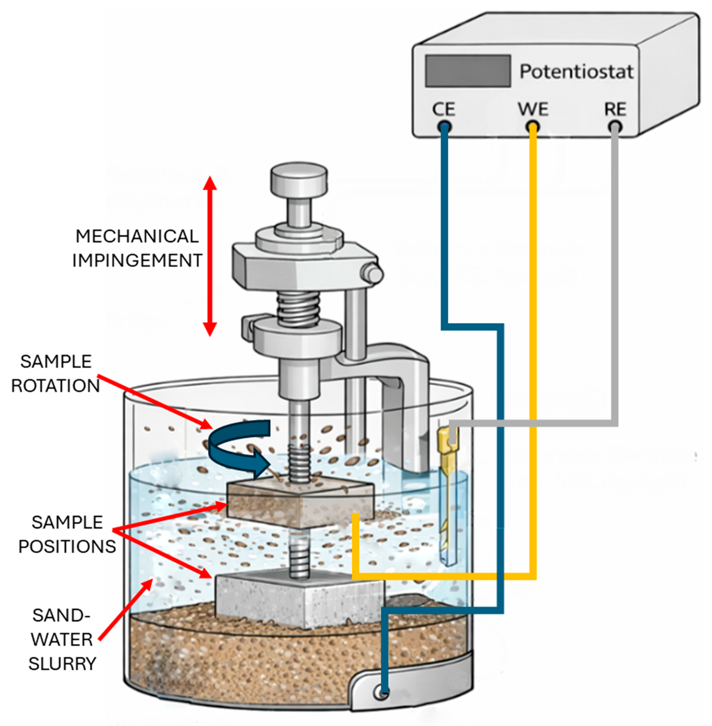
It is seen in the literature that there is a growing interest in coupled erosion–corrosion testing methodologies capable of reproducing service-relevant conditions. While standardized tribocorrosion tests combining sliding wear with in situ electrochemical monitoring are well documented [205], hydro-relevant degradation is frequently governed by silt erosion rather than sliding contact. Addressing this gap, an experimental methodology that integrates a three-electrode electrochemical cell into a Miller slurry abrasion tester, Figure 12, enables direct quantification of abrasion–corrosion synergy and the assessment of mitigation strategies within a single test framework [206]. Such approaches represent an important step toward performance-oriented qualification of coatings for hydro-turbine runners, as they provide mechanistic insight into how mechanical damage alters electrochemical behaviors and vice versa. More importantly, Figure 12 illustrates a broader conceptual shift: coatings are no longer evaluated as isolated materials under simplified loading, but as functional systems exposed to coupled mechanical and electrochemical degradation. This type of testing framework is therefore more consistent with the operating conditions of hydro-turbine runners than conventional single-variable laboratory tests. Future trends in this area point toward the development of standardized, service-representative erosion–corrosion test protocols and performance maps linking operational variables, such as particle size, concentration, flow velocity, and water chemistry, to dominant degradation regimes.
Nevertheless, even coupled laboratory configurations such as that shown in Figure 12 remain only partial representations of real service conditions, since important variables such as cavitation intensity, natural sediment morphology, fluctuating flow regimes, repair-induced surface heterogeneity, and long-term maintenance history are still difficult to reproduce simultaneously in a single setup. Therefore, the future challenge is not only to develop more coupled tests but also to standardize service-representative protocols that enable meaningful comparison between coating systems and provide stronger transferability to field operation.
A similar application-oriented perspective is increasingly required for cavitation-specific coating selection, particularly when cavitation and corrosion act simultaneously. Cavitation erosion is a path-dependent process evolving from incubation to pit formation and spallation, with damage progression strongly influenced by surface integrity and cohesive strength [207,208,209]. When corrosion is present, this evolution can be significantly accelerated, as electrochemical attack weakens near-surface regions, while cavitation repeatedly disrupts protective films. Experimental studies have shown that cavitation performance cannot be reliably predicted from hardness or strength alone [210], nor from cavitation tests conducted in non-representative media. Surface integrity has been shown to lead to simultaneous improvements in cavitation and corrosion resistance under chloride mediums, underscoring the strong coupling between mechanical and electrochemical degradation [211,212], and supporting the industrial practices of polishing the eroded repaired zones of hydro-turbine runners [5]. These findings reinforce the broader principle that service-relevant coating qualification must move beyond isolated material metrics and include the effects of surface finish, defect population, and repair-induced heterogeneity on damage evolution.
This repairing application-driven perspective is well documented in a comparison between fully hard-coated and partially soft-coated Francis-type runners operating under identical sediment-laden conditions at the Kali Gandaki ‘A’ hydro powerplant in Nepal [213]. Despite the conceptual advantage often attributed to soft coatings for impact energy dissipation, the partially soft-coated runner exhibited more severe erosion and cavitation damage, including deeper cavities and non-uniform diameter reduction, primarily due to manual in situ application and the resulting loss of blade-profile fidelity. These observations demonstrate that coating effectiveness in service is strongly influenced by application quality, thickness uniformity, and geometric fidelity, reinforcing the need for performance-driven selection criteria that explicitly account for repair strategy and lifecycle constraints rather than material class alone. In this sense, coating systems for hydro-turbine runners should increasingly be compared not only in terms of microhardness, corrosion potential, or mass-loss rate, but also by application robustness, repair frequency, expected service life, and tolerance to geometric deviation after coating and finishing.
Overall, performance-driven and application-oriented coating design represents a paradigm shift in which coatings are no longer evaluated as isolated material solutions but as integrated elements of a service system defined by degradation synergy, operational environment, repair strategy, and maintenance philosophy. Advancing this approach requires the continued development of coupled testing methodologies, service-relevant performance metrics, and standardized reporting practices that bridge the gap between laboratory studies and in situ performance. More broadly, the future value of coating research in hydropower will depend on how effectively it integrates tribology, corrosion science, process engineering, and maintenance strategy into a coherent qualification framework. By embedding these principles into future research and qualification frameworks, the surface engineering community can provide more actionable guidance for coating selection and deployment, ultimately improving the reliability, sustainability, and cost-effectiveness of hydro-turbine operation.

6. Conclusions and Outlooks

After describing and discussing the wear phenomena that affect hydro-turbine runner integrity, the most-applied repair processes, and the materials deposited, as well as the trends in new materials and possibilities to improve the runners’ life and hydro-turbine efficiency, some conclusions can be drawn:
Cermets, especially WC-Co, are generally most suitable for wear applications due to their industrial maturity and mechanical properties such as hardness and toughness; however, WC-Co is limited to 500 °C, and exposing WC grains to this temperature during coating deposition or operation results in decarburization and performance loss. Cr3C2-NiCr is more stable and resistant to high-temperature exposure but has lower wear performance.
New materials have been studied and promise good alternatives to cermets for wear applications, highlighting HEA, nanostructured coatings, and Fe-based amorphous materials. Among other points, the deposition processes and parameters, powder production costs, and performance reliability still need to be better evaluated.
Developing wear testing closer to a real application would result in more accurate material performance. It requires designing new testing apparatus and optimizing testing parameters, which must be more representative, e.g., using the hydropower station river water instead of laboratory purity water for cavitation and slurry tests, or promoting synergistic tests, like cavitation–corrosion or corrosion–slurry. With the mechanisms’ synergism understood, the next step is standardizing the test for interlaboratory use.
Upscaling new materials from laboratory to industrial use is the biggest challenge for coating deposition because producing a high volume of powder requires a larger infrastructure than the laboratory scale, enrolling powder suppliers. The powder manufacturers and coating shops will only invest in using a new technology if it had been exhaustively studied previously, which is not the case with the emerging materials listed.
Table 2 summarizes the performance and characteristics of hydro-turbine runner coatings, listing different aspects seen in the literature. Many researchers do not follow specific standards, making comparisons of the materials’ performance values unclear. Furthermore, the mechanisms differ for different wear loads and mechanisms, resulting, for example, in an uncertain comparison between a material tested for abrasion and another for cavitation. Among the results collected, those from corrosion tests are the more accurate due to the use of 3.5 wt.% NaCl solution for all the considered works. As described in Table 2, the most mature materials still have some cons for hydro-turbine runner applications, e.g., environmental issues or economic reasons for reducing their use. Consequently, many test results and performance discussions concerning new materials are missing in the literature, showing gaps that scholars must fill.

Author Contributions

Conceptualization, R.F.V.; methodology, R.F.V. and M.L.; formal analysis, R.F.V. and M.L.; investigation, R.F.V., M.L., A.S. and I.G.C.; resources, A.S. and I.G.C.; writing—original draft preparation, R.F.V. and M.L.; writing—review and editing, R.F.V., M.L., A.S. and I.G.C.; supervision, A.S. and I.G.C.; project administration, A.S. and I.G.C.; funding acquisition, A.S. and I.G.C. All authors have read and agreed to the published version of the manuscript.

Funding

The authors acknowledge the support of Grant PID2023-146720OB-C22 funded by Ministerio de Ciencia, Innovación y Universidades (MCIN/AEI/10.13039/501100011033) and by “ERDF A way of making Europe”, by the European Union or by the European Union NextGenerationEU/PRTR.

Data Availability Statement

The data presented in this study are available on request from the corresponding author.

Conflicts of Interest

The authors declare no conflicts of interest.

Abbreviations

The following abbreviations are used in this manuscript:
AMAdditive manufacturing
APSAtmospheric plasma spray
ASIAdiabatic shear instability
CMTCold metal transfer
CSCold spray
CSAMCold spray additive manufacturing
DLCDiamond-like carbon
EBSDElectron beam scattering diffraction
EcorrCorrosion potential
FEAFinite elements analysis
FGCFunctionally graded coatings
FSFlame spray
GMAWGas metal arc welding
GTAWGas tungsten arc welding
HAZHeat affected zone
HTHeat treatment
HVAFHigh-velocity air-fuel
HVOFHigh-velocity oxy-fuel
icorrCorrosion current
L-PBFLaser powder bed fusion
MAMechanical alloying
MEXMaterial extrusion
MMLMaterial maturity level
NDTNondestructive testing
PTAPlasma transferred arc
PVDPhysical vapor deposition
PWHTPost-weld heat treatment
SCCStress corrosion cracking
SEMScanning electron microscopy
SMAWShielded metal arc welding
TWEATwin-wire arc-spray
WAAMWire arc additive manufacturing
XRDX-ray diffraction

References

  1. Taylor, R. Hydropower. In 2004 Survey of Energy Resources; Trinnaman, J., Clarke, A., Eds.; Elsevier: Amsterdam, The Netherlands, 2004; pp. 199–232. [Google Scholar]
  2. Zarawi, M.I.S.; Afian, M.A.; Rezal, M.A.H.M.; Raie, M.A.M.; Jun, N.Z.; Ramu, J.N.A.; Muzir, N.A.Q.; Sapari, N.M. A Review of Efficiency Improvement of Hydro-Turbine Generator. J. Energy Saf. Technol. 2025, 8, 113–120. [Google Scholar]
  3. Kumar, R.; Singal, S.K. Operation and Maintenance Problems in Hydro Turbine Material in Small Hydro Power Plant. Mater. Today Proc. 2015, 2, 2323–2331. [Google Scholar] [CrossRef]
  4. Bezerra Leite Neto, P.; Ronald Saavedra, O.; Camelo, N.J.; de Souza Ribeiro, L.A.; Ferreira, R.M. Exploração de Energia Maremotriz Para Geração de Eletricidade: Aspectos Básicos e Principais Tendências. Ingeniare. Rev. Chil. Ing. 2011, 19, 219–232. [Google Scholar] [CrossRef][Green Version]
  5. Váz, R.F.; Tristante, R.; Pukasiewicz, A.G.M.; Capra, A.R.; Chicoski, A.; Filippin, C.G.; Paredes, R.S.C.; Henke, S.L. Welding and Thermal Spray Processes for Maintenance of Hydraulic Turbine Runners: Case Studies. Soldag. Insp. 2021, 26, e2540. [Google Scholar] [CrossRef]
  6. Bhatia, S.C. Hydroelectric Power. In Advanced Renewable Energy Systems; Bhatia, S.C., Ed.; Elsevier: New Delhi, India, 2014; pp. 240–269. [Google Scholar]
  7. ASTM A743/A743M-03; Specification for Castings, Iron-Chromium, Iron-Chromium-Nickel, Corrosion Resistant, for General Application. ASTM: West Conshohocken, PA, USA, 2003; pp. 1–6.
  8. Liu, P.; Ma, J.; Fang, Y.; Xu, B.; Qiu, L. Effect of Repeated Weld Repairs on Microstructure and Mechanical Properties of Heat-Affected Zone in CA6NM Stainless Steel. Adv. Mater. Sci. Eng. 2022, 2022, 4527917. [Google Scholar] [CrossRef]
  9. Han, X.; Li, J.; Liu, Q.; Lu, S. CNC Machining Optimization of Hydro-Turbine Runner Blade Based on VERICUT. J. Phys. Conf. Ser. 2023, 2541, 012024. [Google Scholar] [CrossRef]
  10. Auyeskhan, U.; Lee, T.; Park, Y.; Kim, D.; Kim, D.; Kim, N.K.C. Design Study for Performance Improvement of a Hybrid Pico Pelton Turbine and Its Additive Manufacturing Using a Laser Powder Bed Fusion Method. Int. J. Interact. Des. Manuf. 2024, 18, 107–117. [Google Scholar] [CrossRef]
  11. Managi, I.W.M.; Yasa, I.M.A.; Antara, I.N.L.; Wibawa, M.A.S.; Suparta, I.N.; Suarbawa, K.G.J. Development of a 3D-Printed Cross-Flow Turbine Prototype for Pico-Hydro Power Generation as a Sustainable Renewable Energy Source. In Proceedings of the International Conference on Sustainable Green Tourism Applied Science–Engineering Applied Science 2025 (ICOSTAS-EAS 2025); Sapteka, A.A.N.G., Wiratama, I.K., Moi, F., Widantha, K.W., Septevany, E., Dewi, D.A.I.C., Mariani, W.E., Fakhrurozi, R.N., Eds.; Atlantis Press: Bali, Indonesia, 2025; pp. 122–132. [Google Scholar]
  12. Xiong, X.; Qin, X.; Hua, L.; Wan, G.; Wei, S.; Ni, M.; Hu, Z. Grain Refinement and Strengthening Mechanisms of In-Situ Follow-up Hammering-Assisted Wire Arc Additive Manufacturing for Hydraulic Turbine Blade Repairing. Met. Mater. Int. 2023, 29, 1796–1814. [Google Scholar] [CrossRef]
  13. Sharma, D.; Khadka, B.; Parajuli, A.; Dahal, D.R.; Thapa, B. Effect of Welding Pattern during Repair and Maintenance of Francis Runner on Sediment Erosion: An Experimental Investigation Using RDA. J. Phys. Conf. Ser. 2020, 1608, 012011. [Google Scholar] [CrossRef]
  14. Biner, D.; Hasmatuchi, V.; Dujic, D.; Münch-Alligné, C. Fatigue Design of Francis-Type Pump-Turbine Runners under Flexible Power Generation. Results Eng. 2026, 29, 109480. [Google Scholar] [CrossRef]
  15. Pukasiewicz, A.G.M.; Sucharski, G.B.; de Araújo Ferandes Siqueira, I.B.; de Andrade, J.; Váz, R.F.; Alberto, L.; Procopiak, J. Corrosion Resistance of Iron-Based Alloy Coatings Deposited by HVOF Process. In Proceedings of the International Thermal Spray Conference, Yokohama, Japan, 26 May 2019; Azarmi, F., Balani, K., Koivuluoto, H., Lau, Y., Li, H., Shinoda, K., Toma, F., Veilleux, J., Widener, C., Eds.; ASM International: Almere, The Netherlands, 2019; pp. 359–368. [Google Scholar]
  16. Kadivar, E.; Kumar, P. A Review of Hydrodynamic Cavitation Passive and Active Control Methods in Marine Engineering Applications. Symmetry 2025, 17, 1782. [Google Scholar] [CrossRef]
  17. Soyama, H. Cavitating Jet: A Review. Appl. Sci. 2020, 10, 7280. [Google Scholar] [CrossRef]
  18. Wu, P.; Bai, L.; Lin, W. On the Definition of Cavitation Intensity. Ultrason. Sonochem. 2020, 67, 105141. [Google Scholar] [CrossRef] [PubMed]
  19. Kumar, P.; Saini, R.P. Study of Cavitation in Hydro Turbines—A Review. Renew. Sustain. Energy Rev. 2010, 14, 374–383. [Google Scholar] [CrossRef]
  20. Rakibuzzaman, M.; Kim, H.-H.; Kim, K.; Suh, S.-H.; Kim, K.Y. Numerical Study of Sediment Erosion Analysis in Francis Turbine. Sustainability 2019, 11, 1423. [Google Scholar] [CrossRef]
  21. Padhy, M.K.; Saini, R.P. Study of Silt Erosion on Performance of a Pelton Turbine. Energy 2011, 36, 141–147. [Google Scholar] [CrossRef]
  22. Kashyap, T.; Thakur, R.; Ngo, G.H.; Lee, D.; Fekete, G.; Kumar, R.; Singh, T. Silt Erosion and Cavitation Impact on Hydraulic Turbines Performance: An in-Depth Analysis and Preventative Strategies. Heliyon 2024, 10, e28998. [Google Scholar] [CrossRef] [PubMed]
  23. Kumar, P.; Singal, S.K.; Gohil, P.P. A Technical Review on Combined Effect of Cavitation and Silt Erosion on Francis Turbine. Renew. Sustain. Energy Rev. 2024, 190, 114096. [Google Scholar] [CrossRef]
  24. Luiz, L.A.; de Andrade, J.; Pesqueira, C.M.; de Araújo Fernandes Siqueira, I.B.; Sucharski, G.B.; de Sousa, M.J. Corrosion Behavior and Galvanic Corrosion Resistance of WC and Cr3C2 Cermet Coatings in Madeira River Water. J. Therm. Spray Technol. 2021, 30, 205–221. [Google Scholar] [CrossRef] [PubMed]
  25. Saggu, H.S. Contending Erosion in Hydro Turbine for Moderate Temperature Applications. J. Emerg. Technol. Innov. Res. 2019, 6, 670–673. [Google Scholar]
  26. Padhy, M.K.; Saini, R.P. A Review on Silt Erosion in Hydro Turbines. Renew. Sustain. Energy Rev. 2008, 12, 1974–1987. [Google Scholar] [CrossRef]
  27. Padhy, M.K.; Saini, R.P. Study of Silt Erosion Mechanism in Pelton Turbine Buckets. J. Emerg. Technol. Innov. Res. 2018, 5, 556–560. [Google Scholar] [CrossRef]
  28. Shrestha, R.; Gurung, P.; Chitrakar, S.; Thapa, B.; Neopane, H.P.; Guo, Z.; Qian, Z. Review on Experimental Investigation of Sediment Erosion in Hydraulic Turbines. Front. Mech. Eng. 2024, 10, 1526120. [Google Scholar] [CrossRef]
  29. Nobilo, M.; Salehi, S.; Nilsson, H. Lifetime Analysis of Hydro Turbines with Focus on Fatigue Damage in a Renewable Energy System—A Review. Renew. Sustain. Energy Rev. 2026, 228, 116578. [Google Scholar] [CrossRef]
  30. Muser, T.; Krymova, E.; Morabito, A.; Seydoux, M.; Vagnoni, E. Fatigue Damage Reduction in Hydropower Startups with Machine Learning. Nat. Commun. 2025, 16, 2961. [Google Scholar] [CrossRef] [PubMed]
  31. Chen, H.; Pan, J.; Wang, S.; Ma, J.; Zhang, W. Fatigue Damage Assessment of Turbine Runner Blades Considering Sediment Wear. Appl. Sci. 2024, 14, 4660. [Google Scholar] [CrossRef]
  32. Zhang, M.; Valentín, D.; Valero, C.; Egusquiza, M.; Egusquiza, E. Failure Investigation of a Kaplan Turbine Blade. Eng. Fail. Anal. 2019, 97, 690–700. [Google Scholar] [CrossRef]
  33. Khalid Mohammed Ridha, W.; Reza Kashyzadeh, K.; Ghorbani, S. Common Failures in Hydraulic Kaplan Turbine Blades and Practical Solutions. Materials 2023, 16, 3303. [Google Scholar] [CrossRef]
  34. Seleznev, V.S.; Liseikin, A.V.; Bryksin, A.A.; Gromyko, P.V. What Caused the Accident at the Sayano-Shushenskaya Hydroelectric Power Plant (SSHPP): A Seismologist’s Point of View. Seismol. Res. Lett. 2014, 85, 817–824. [Google Scholar] [CrossRef]
  35. Serrano-Munoz, I.; Buffiere, J.-Y.; Mokso, R.; Verdu, C.; Nadot, Y. Location, Location & Size: Defects Close to Surfaces Dominate Fatigue Crack Initiation. Sci. Rep. 2017, 7, 45239. [Google Scholar] [CrossRef] [PubMed]
  36. Zhao, B.; Song, J.; Xie, L.; Hu, Z.; Chen, J. Surface Roughness Effect on Fatigue Strength of Aluminum Alloy Using Revised Stress Field Intensity Approach. Sci. Rep. 2021, 11, 19279. [Google Scholar] [CrossRef] [PubMed]
  37. Li, C.; Han, S.; Wang, C.; Amanov, A.; Wang, L.; Abdel Wahab, M. A Multiscale Finite Element Approach to Analyse the Effect of Shot Peening-Induced Surface Roughness on Fretting Fatigue Crack Initiation. Results Eng. 2025, 26, 104998. [Google Scholar] [CrossRef]
  38. Reza Kashyzadeh, K.; Ridha, W.K.M.; Ghorbani, S. The Influence of Nanocoatings on the Wear, Corrosion, and Erosion Properties of AISI 304 and AISI 316L Stainless Steels: A Critical Review Regarding Hydro Turbines. Corros. Mater. Degrad. 2025, 6, 6. [Google Scholar] [CrossRef]
  39. Wood, R.J.K. Tribo-Corrosion of Coatings: A Review. J. Phys. D Appl. Phys. 2007, 40, 5502–5521. [Google Scholar] [CrossRef]
  40. Silveira, L.L.; Pukasiewicz, A.G.M.; de Aguiar, D.J.M.; Zara, A.J.; Björklund, S. Study of the Corrosion and Cavitation Resistance of HVOF and HVAF FeCrMnSiNi and FeCrMnSiB Coatings. Surf. Coat. Technol. 2019, 374, 910–922. [Google Scholar] [CrossRef]
  41. Dobson, T.; Larrosa, N.; Coules, H. The Role of Corrosion Pit Topography on Stress Concentration. Eng. Fail. Anal. 2024, 157, 107900. [Google Scholar] [CrossRef]
  42. Vijaya Prakash, B.; Murali, B.; Muthu Kumaran, A.; Pandiyarajan, V.; Shailendra Kumar, B.; Duraimurugan, P. Corrosion-Fatigue Properties of 13%Cr4%Ni Steel ForHydroturbine Components. Mater. Today Proc. 2024, in press. [Google Scholar] [CrossRef]
  43. Ehrnstén, U.; Andresen, P.L.; Que, Z. A Review of Stress Corrosion Cracking of Austenitic Stainless Steels in PWR Primary Water. J. Nucl. Mater. 2024, 588, 154815. [Google Scholar] [CrossRef]
  44. Dobrzanski, L.A.; Polok, M.; Panjan, P.; Bugliosi, S.; Adamiak, M. Improvement of Wear Resistance of Hot Work Steels by PVD Coatings Deposition. J. Mater. Process. Technol. 2004, 155–156, 1995–2001. [Google Scholar] [CrossRef]
  45. Rovani, A.C.; Breganon, R.; de Souza, G.S.; Brunatto, S.F.; Pintaúde, G. Scratch Resistance of Low-Temperature Plasma Nitrided and Carburized Martensitic Stainless Steel. Wear 2017, 376–377, 70–76. [Google Scholar] [CrossRef]
  46. Cheng, F.; Wu, F.; Liu, L.; Yang, S.; Ji, W. Investigation on Cavitation Erosion of Diamond-like Carbon Films with Heterogeneous Multilayer Structure. Surf. Coat. Technol. 2021, 405, 126682. [Google Scholar] [CrossRef]
  47. Vaz, R.F.; Albaladejo-Fuentes, V.; Sanchez, J.; Ocaña, U.; Corral, Z.G.; Canales, H.; Cano, I.G. Metal Knitting: A New Strategy for Cold Gas Spray. Materials 2022, 15, 6785. [Google Scholar] [CrossRef]
  48. Vargas-Uscategui, A.; King, P.C.; Yang, S.; Chu, C.; Li, J. Toolpath Planning for Cold Spray Additively Manufactured Titanium Walls and Corners: Effect on Geometry and Porosity. J. Mater. Process. Technol. 2021, 298, 117272. [Google Scholar] [CrossRef]
  49. Garfias, A.; Vaz, R.; Albaladejo-Fuentes, V.; Sánchez, J.; Cano, I.G. Geometry and Microstructure Control of Remanufactured Metallic Parts by Cold Spray Additive Manufacturing. Materials 2023, 16, 4735. [Google Scholar] [CrossRef]
  50. Ang, A.S.M.; Sanpo, N.; Sesso, M.L.; Kim, S.Y.; Berndt, C.C. Thermal Spray Maps: Material Genomics of Processing Technologies. J. Therm. Spray Technol. 2013, 22, 1170–1183. [Google Scholar] [CrossRef]
  51. Sunitha, K.; Vasudev, H. A Short Note on the Various Thermal Spray Coating Processes and Effect of Post-Treatment on Ni-Based Coatings. Mater. Today Proc. 2022, 50, 1452–1457. [Google Scholar] [CrossRef]
  52. Fauchais, P.; Vardelle, A.; Dussoubs, B. Quo vadis Thermal Spraying? J. Therm. Spray Technol. 2001, 10, 44–66. [Google Scholar] [CrossRef]
  53. Crawmer, D.E. Thermal Spray Processes. In Handbook of Thermal Spray Technology; Davis, J.R., Ed.; ASM International: Novelty, OH, USA, 2004; pp. 54–76. [Google Scholar]
  54. Tucker, R.C. Thermal Spray Coatings. In ASM Hanbook Vol 5: Surface Engineering; Cotell, C.M., Sprague, J.A., Smidt, F.A., Jr., Eds.; ASM International: Materials Park, OH, USA, 1990; Volume 5, pp. 1446–1471. [Google Scholar]
  55. Vaz, R.F.; Pukasiewicz, A.G.M.; Fals, H.D.C.; Lourençato, L.A.; Paredes, R.S.C. Study of Particle Properties of Different Steels Sprayed by Arc Spray Process. Coatings 2020, 10, 417. [Google Scholar] [CrossRef]
  56. Anusha, K.; Routara, B.C.; Guha, S. A Review on High-Velocity Oxy-Fuel (HVOF) Coating Technique. J. Inst. Eng. Ser. D 2023, 104, 831–848. [Google Scholar] [CrossRef]
  57. Boronenkov, V.; Korobov, Y. Fundamentals of Arc Spraying; Springer International Publishing: Cham, Switzerland, 2016. [Google Scholar]
  58. Elshalakany, A.B.; Osman, T.A.; Hoziefa, W.; Escuder, A.V.; Amigó, V. Comparative Study between High-Velocity Oxygen Fuel and Flame Spraying Using MCrAlY Coats on a 304 Stainless Steel Substrate. J. Mater. Res. Technol. 2019, 8, 4253–4263. [Google Scholar] [CrossRef]
  59. Kuroda, S.; Watanabe, M.; Kim, K.; Katanoda, H. Current Status and Future Prospects of Warm Spray Technology. J. Therm. Spray Technol. 2011, 20, 653–676. [Google Scholar] [CrossRef]
  60. Lamana, M.S.; Pukasiewicz, A.G.M.; Sampath, S. Influence of Cobalt Content and HVOF Deposition Process on the Cavitation Erosion Resistance of WC-Co Coatings. Wear 2018, 398–399, 209–219. [Google Scholar] [CrossRef]
  61. Vishnoi, M.; Kumar, P.; Murtaza, Q. A Review on Coating for Hydro-Turbine Application by HVOF Process. In Advances in Materials Engineering and Manufacturing Processes; Singh, I., Bajpai, P.K., Panwar, K., Eds.; Springer: Singapore, 2020; pp. 79–103. [Google Scholar]
  62. Aryal, S.; Chitrakar, S.; Shrestha, R.; Jha, A. kumar Coating Technology in Hydro-Turbines for Sediment Affected Power Plants: A Review. IOP Conf. Ser. Earth Environ. Sci. 2022, 1037, 012021. [Google Scholar] [CrossRef]
  63. Devaraj, S.; Anand, B.; Gibbons, M.; McDonald, A.; Chandra, S. Thermal Spray Deposition of Aluminum and Zinc Coatings on Thermoplastics. Surf. Coat. Technol. 2020, 399, 126114. [Google Scholar] [CrossRef]
  64. Kuzmin, V.I.; Gulyaev, I.P.; Sergachev, D.V.; Vashchenko, S.P.; Palagushkin, B.V.; Tokarev, A.O.; Menzilova, M.G. Air-Plasma Spraying of Cavitation- and Hydroabrasive-Resistant Coatings. Thermophys. Aeromech. 2020, 27, 285–294. [Google Scholar] [CrossRef]
  65. Wang, H.; Wang, X.; Song, X.; Liu, X.; Liu, X. Sliding Wear Behavior of Nanostructured WC–Co–Cr Coatings. Appl. Surf. Sci. 2015, 355, 453–460. [Google Scholar] [CrossRef]
  66. Pukasiewicz, A.G.M.; de Oliveira, W.R.; Váz, R.F.; de Souza, G.B.; Serbena, F.C.; Dosta, S.; Cano, I.G. Influence of the Deposition Parameters on the Tribological Behavior of Cold Gas Sprayed FeMnCrSi Alloy Coatings. Surf. Coat. Technol. 2021, 428, 127888. [Google Scholar] [CrossRef]
  67. Santacruz, G.; Albaladejo, V.; Silvello, A.; Vaz, R.F.; Bergmann, C.P.; Cano, I.G. The Critical Role of Liquid Surface Tension in Determining Cavitation Erosion and Dry Wear Performance of WC-17Co Coatings Produced by Cold Spray Technology. Tribol. Int. 2025, 208, 110609. [Google Scholar] [CrossRef]
  68. Sharma, V.; Kaur, M.; Bhandari, S. Development and Characterization of High-Velocity Flame Sprayed Ni/TiO2/Al2O3 Coatings on Hydro Turbine Steel. J. Therm. Spray Technol. 2019, 28, 1379–1401. [Google Scholar] [CrossRef]
  69. Vaz, R.; Garfias, A.; Albaladejo, V.; Sanchez, J.; Cano, I. A Review of Advances in Cold Spray Additive Manufacturing. Coatings 2023, 13, 267. [Google Scholar] [CrossRef]
  70. Schmidt, T.; Gärtner, F.; Assadi, H.; Kreye, H. Development of a Generalized Parameter Window for Cold Spray Deposition. Acta Mater. 2006, 54, 729–742. [Google Scholar] [CrossRef]
  71. Adaan-Nyiak, M.A.; Tiamiyu, A.A. Recent Advances on Bonding Mechanism in Cold Spray Process: A Review of Single-Particle Impact Methods. J. Mater. Res. 2023, 38, 69–95. [Google Scholar] [CrossRef] [PubMed]
  72. Assadi, H.; Gärtner, F.; Stoltenhoff, T.; Kreye, H. Bonding Mechanism in Cold Gas Spraying. Acta Mater. 2003, 51, 4379–4394. [Google Scholar] [CrossRef]
  73. Silva, H.R.; Ferraresi, V.A. Effect of Cobalt Alloy Addition in Erosive Wear and Cavitation of Coatings Welds. Wear 2019, 426–427, 302–313. [Google Scholar] [CrossRef]
  74. Xiaojun, Z.; Procopiak, L.A.J.; Souza, N.C.; D’Oliveira, A.S.C.M. Phase Transformation during Cavitation Erosion of a Co Stainless Steel. Mater. Sci. Eng. A 2003, 358, 199–204. [Google Scholar] [CrossRef]
  75. Moreno, J.R.S.; Pinto, H.C.; Correa, C.A.; Mastelari, N.; Marin, L.G.; Silva, E.; Ávila, J.A. Cladding Welding of CA6M with Pulsed FCAW and Results Analysis through the L9 TAGUCHI and ANOVA. Int. J. Adv. Eng. Res. Sci. 2018, 5, 150–157. [Google Scholar] [CrossRef][Green Version]
  76. Singh, B.; Zafar, S. Microstructural and Mechanical Aspects of Micrometric and Nanometric Ni + 10% Cr7C3 Composite Microwave Clads. J. Compos. Mater. 2021, 55, 347–360. [Google Scholar] [CrossRef]
  77. de Gouveia, R.R.; Pukasiewicz, A.G.M.; Capra, A.R.; Henke, S.L.; Okimoto, P.C. Effect of Interpass Temperature on Microstructure, Impact Toughness and Fatigue Crack Propagation in Joints Welded Using the GTAW Process on Steel ASTM A743-CA6NM. Weld. Int. 2015, 29, 433–440. [Google Scholar] [CrossRef]
  78. Lima, C.R.C.; Belém, M.J.X.; Fals, H.D.C.; Rovere, C.A. Della Wear and Corrosion Performance of Stellite 6® Coatings Applied by HVOF Spraying and GTAW Hotwire Cladding. J. Mater. Process. Technol. 2020, 284, 116734. [Google Scholar] [CrossRef]
  79. Singh, S.; Goyal, D.K.; Kumar, P.; Bansal, A. Laser Cladding Technique for Erosive Wear Applications: A Review. Mater. Res. Express 2020, 7, 012007. [Google Scholar] [CrossRef]
  80. Liu, X.; Meng, L.; Zeng, X.; Zhu, B.; Cao, J.; Wei, K.; Hu, Q. Study on the Microstructure, Mechanical Properties and Cavitation Erosion Resistance of 17-4PH Alloy Coatings Fabricated by High Power Laser Cladding. Surf. Coat. Technol. 2024, 494, 131451. [Google Scholar] [CrossRef]
  81. Perez, J.; Gutierrez, J.; Olaya, J.; Piamba, O.; Scotti, A. Influence of Niobium Content on the Chemical Composition, Microstructure, and Microhardness of Hardfacing Coatings Applied by SMAW. Materials 2025, 18, 5477. [Google Scholar] [CrossRef]
  82. Rao, A.S. Influence of Surface Finish on Cavitation Erosion. In Proceedings of the Waterpower ’99: Hydro’s Future: Technology, Markets, and Policy, Las Vegas, NV, USA, 5 July 1999; American Society of Civil Engineers: Reston, VA, USA, 1999; pp. 1–9. [Google Scholar]
  83. He, J.; Wei, M.; Zhang, L.; Ren, C.; Wang, J.; Wang, Y.; Qi, W. Effect of Preheat Temperature and Welding Sequence on the Temperature Distribution and Residual Stress in the Weld Overlay Repair of Hydroturbine Runner. Materials 2022, 15, 4867. [Google Scholar] [CrossRef]
  84. Romo, S.A.; Santa, J.F.; Giraldo, J.E.; Toro, A. Cavitation and High-Velocity Slurry Erosion Resistance of Welded Stellite 6 Alloy. Tribol. Int. 2012, 47, 16–24. [Google Scholar] [CrossRef]
  85. Zhang, S.; Wang, S.; Wu, C.L.; Zhang, C.H.; Guan, M.; Tan, J.Z. Cavitation Erosion and Erosion-Corrosion Resistance of Austenitic Stainless Steel by Plasma Transferred Arc Welding. Eng. Fail. Anal. 2017, 76, 115–124. [Google Scholar] [CrossRef]
  86. Singh, H. Challenges of Corrosion, Wear, Erosion, and Abrasion in Hydropower Plants: Materials, Modeling, and Mitigation Strategies. Eng. Trans. 2026, in press. [Google Scholar] [CrossRef]
  87. Vaz, R.F.; Silveira, L.L.; Cruz, J.R.; Pukasiewicz, A.G.M. Cavitation Resistance of FeMnCrSi Coatings Processed by Different Thermal Spray Processes. Hybrid Adv. 2024, 5, 100125. [Google Scholar] [CrossRef]
  88. Bellamkonda, P.N.; Dwivedy, M.; Addanki, R. Cold Metal Transfer Technology—A Review of Recent Research Developments. Results Eng. 2024, 23, 102423. [Google Scholar] [CrossRef]
  89. Iqbal, M.A.; Skotnicová, K.; Shafiq, A.; Sindhu, T.N. Microstructure and Properties Evolution of Dual-Layer Pulsed GTAW Cladded Inconel 625 Coatings on API 5 L Grade B Carbon Steel by Controlled Iron Dilution. Colloids Surf. A Physicochem. Eng. Asp. 2025, 727, 138322. [Google Scholar] [CrossRef]
  90. d’Oliveira, A.S.C.M.; Paredes, R.S.C.; Santos, R.L.C. Pulsed Current Plasma Transferred Arc Hardfacing. J. Mater. Process. Technol. 2006, 171, 167–174. [Google Scholar] [CrossRef]
  91. Farzadi, A.; Kalantarian, R. Microstructural Development and Corrosion Behavior of 13Cr–4Ni-1Mo Martensitic Stainless Steel Clad. Weld. World 2020, 64, 1811–1823. [Google Scholar] [CrossRef]
  92. Divya, M.; Das, C.R.; Ramasubbu, V.; Albert, S.K.; Bhaduri, A.K. Improving 410NiMo Weld Metal Toughness by PWHT. J. Mater. Process. Technol. 2011, 211, 2032–2038. [Google Scholar] [CrossRef]
  93. Boudreault, E.; Hazel, B.; Côté, J.; Godin, S. In Situ Post-Weld Heat Treatment on Martensitic Stainless Steel Turbine Runners Using a Robotic Induction Heating Process to Control Temperature Distribution. IOP Conf. Ser. Earth Environ. Sci. 2014, 22, 012016. [Google Scholar] [CrossRef]
  94. Wang, P.; Lu, S.P.; Xiao, N.M.; Li, D.Z.; Li, Y.Y. Effect of Delta Ferrite on Impact Properties of Low Carbon 13Cr–4Ni Martensitic Stainless Steel. Mater. Sci. Eng. A 2010, 527, 3210–3216. [Google Scholar] [CrossRef]
  95. Carrouge, D.; Bhadeshia, H.K.D.H.; Woollin, P. Effect of δ-Ferrite on Impact Properties of Supermartensitic Stainless Steel Heat Affected Zones. Sci. Technol. Weld. Join. 2004, 9, 377–389. [Google Scholar] [CrossRef]
  96. Pukasiewicz, A.G.M.; Henke, S.L.; Casas, W.J.P. Effect of Post-Weld Heat Treatment on Fatigue Crack Propagation in Welded Joints in CA6NM Martensite Stainless Steel. Weld. Int. 2006, 20, 947–952. [Google Scholar] [CrossRef]
  97. Zappa, S.; Svoboda, H.G.; Surian, E. Supermartensitic Stainless Steel Deposits: Effects of Shielding Gas and Postweld Heat Treatment. Weld. J. 2013, 92, 297.S–303.S. [Google Scholar]
  98. Gendron, M.; Hazel, B.; Boudreault, E.; Champliaud, H.; Pham, X.-T. Coupled Thermo-Electromagnetic Model of a New Robotic High-Frequency Local Induction Heat Treatment System for Large Steel Components. Appl. Therm. Eng. 2019, 150, 372–385. [Google Scholar] [CrossRef]
  99. Li, Z.; Yang, P.; Yang, Y.; Lu, G.; Tang, Y. Hydropower Preventive Maintenance Scheduling in a Deregulated Market: A Multi-Stage Stochastic Programming Approach. Electr. Power Syst. Res. 2023, 221, 109379. [Google Scholar] [CrossRef]
  100. Li, L.; Wu, Y.; Han, Y.; Xu, Z.; Wu, X.; Luo, Y.; Shen, J. Problems and Strategies for Maintenance Scheduling of a Giant Cascaded Hydropower System in the Lower Jinsha River. Energies 2025, 18, 3831. [Google Scholar] [CrossRef]
  101. de Sousa Oliveira, P.; de Oliveira, M.T.B.; Oliveira, E.; Conceicao, L.R.; Marcato, A.L.M.; Junqueira, G.S.; de Alencar Junior, C.A.V. Maintenance Schedule Optimization Applied to Large Hydroelectric Plants: Towards a Methodology Encompassing Regulatory Aspects. IEEE Access 2021, 9, 29883–29894. [Google Scholar] [CrossRef]
  102. Eggen, A.O.; Belsnes, M. Operation Related Maintenance and Reinvestment Costs for Hydropower Scheduling. Energy Syst. 2023. [Google Scholar] [CrossRef]
  103. D’Andrea, A.; Gagnon, M.; Beretta, S.; Bocher, P. Measurements and Prediction of Extreme Defect Distributions for Fatigue Assessment in Multi-Pass Weld of 13%Cr–4%Ni Alloy for Hydraulic Turbines. Int. J. Fatigue 2024, 188, 108501. [Google Scholar] [CrossRef]
  104. Hattori, S.; Mikami, N. Cavitation Erosion Resistance of Stellite Alloy Weld Overlays. Wear 2009, 267, 1954–1960. [Google Scholar] [CrossRef]
  105. Lavigne, S.; Pougoum, F.; Savoie, S.; Martinu, L.; Klemberg-Sapieha, J.E.; Schulz, R. Cavitation Erosion Behavior of HVOF CaviTec Coatings. Wear 2017, 386–387, 90–98. [Google Scholar] [CrossRef]
  106. Diaz, V.V.; Dutra, J.C.; D’Oliveira, A.S.C.M. Hardfacing by Plasma Transfer Arc Process. Weld. Int. 2012, 26, 87–95. [Google Scholar] [CrossRef]
  107. Hong, S.; Lin, J.; Wu, Y.; Wu, J.; Zheng, Y.; Zhang, Y.; Cheng, J.; Sun, W. Cavitation Erosion Characteristics at Various Flow Velocities in NaCl Medium of Carbide-Based Cermet Coatings Prepared by HVOF Spraying. Ceram. Int. 2021, 47, 1929–1939. [Google Scholar] [CrossRef]
  108. Ding, X.; Huang, Y.; Yuan, C.; Ding, Z. Deposition and Cavitation Erosion Behavior of Multimodal WC-10Co4Cr Coatings Sprayed by HVOF. Surf. Coat. Technol. 2020, 392, 125757. [Google Scholar] [CrossRef]
  109. Zhang, H.; Chen, X.; Gong, Y.; Tian, Y.; McDonald, A.; Li, H. In-Situ SEM Observations of Ultrasonic Cavitation Erosion Behavior of HVOF-Sprayed Coatings. Ultrason. Sonochem. 2020, 60, 104760. [Google Scholar] [CrossRef] [PubMed]
  110. Pukasiewicz, A.G.M.; de Boer, H.E.; Sucharski, G.B.; Vaz, R.F.; Procopiak, L.A.J. The Influence of HVOF Spraying Parameters on the Microstructure, Residual Stress and Cavitation Resistance of FeMnCrSi Coatings. Surf. Coat. Technol. 2017, 327, 158–166. [Google Scholar] [CrossRef]
  111. Lekatou, A.; Sioulas, D.; Karantzalis, A.E.; Grimanelis, D. A Comparative Study on the Microstructure and Surface Property Evaluation of Coatings Produced from Nanostructured and Conventional WC–Co Powders HVOF-Sprayed on Al7075. Surf. Coat. Technol. 2015, 276, 539–556. [Google Scholar] [CrossRef]
  112. Xing, Z.; Wang, N.; Fan, L.; Shang, L.; Yu, L. Investigation of the Corrosion Performance of HVOF-Sprayed WC-CoCr Coatings Applied on Offshore Hydraulic Equipment. Rev. Adv. Mater. Sci. 2025, 64, 20240066. [Google Scholar] [CrossRef]
  113. Govande, A.R.; Chandak, A.; Sunil, B.R.; Dumpala, R. Carbide-Based Thermal Spray Coatings: A Review on Performance Characteristics and Post-Treatment. Int. J. Refract. Met. Hard Mater. 2022, 103, 105772. [Google Scholar] [CrossRef]
  114. Santa, J.F.; Espitia, L.A.; Blanco, J.A.; Romo, S.A.; Toro, A. Slurry and Cavitation Erosion Resistance of Thermal Spray Coatings. Wear 2009, 267, 160–167. [Google Scholar] [CrossRef]
  115. Rúa Ramirez, E.; Silvello, A.; Torres Diaz, E.; Vaz, R.F.; Cano, I.G. A Comparative Study of the Life Cycle Inventory of Thermally Sprayed WC-12Co Coatings. Metals 2024, 14, 431. [Google Scholar] [CrossRef]
  116. Wayne, S.F.; Sampath, S. Structure/Property Relationships in Sintered and Thermally Sprayed WC-Co. J. Therm. Spray Technol. 1992, 1, 307–315. [Google Scholar] [CrossRef]
  117. He, D.; Hu, H.; Li, R.; Liang, Y.; Duan, W.; Deng, X.; Jiang, Q.; Tan, W.; Cheng, F.; Guo, F. Microstructural and Mechanical Property Enhancement in a Low-Co Cemented Carbide via a Cold Isostatic Pressing-Assisted Binder Jetting Route. Int. J. Refract. Met. Hard Mater. 2026, 136, 107620. [Google Scholar] [CrossRef]
  118. Brezinová, J.; Guzanová, A.; Draganovská, D.; Brezina, J. Characterization of Selected Properties of WC–WB–Co and WC–FeCrAl Coatings Applied by HVOF Technology. Koroze Ochr. Mater. 2019, 63, 167–173. [Google Scholar] [CrossRef]
  119. Hofmann, M.; Hofmann, H.; Hagelüken, C.; Hool, A. Critical Raw Materials: A Perspective from the Materials Science Community. Sustain. Mater. Technol. 2018, 17, e00074. [Google Scholar] [CrossRef]
  120. Hool, A.; Helbig, C.; Wierink, G. Challenges and Opportunities of the European Critical Raw Materials Act. Miner. Econ. 2024, 37, 661–668. [Google Scholar] [CrossRef]
  121. Potempa, M.; Myćka, Ł.; Kortyka, Ł.; Madej, P.; Sak, T.; Jako Surowiec Krytyczny, K. Critical Raw Material Cobalt as a Critical Raw Material. Polish Tech. Rev. 2021, 1, 2–9. [Google Scholar] [CrossRef]
  122. Li, Y.; Ma, J.; Yu, W. Aplication of Nanotechnology on Hydraulic Turbine Abrasion and Erosion. In Proceedings of the 2010 International Conference on Power System Technology; IEEE: New York, NY, USA, 2010; pp. 1–3. [Google Scholar]
  123. Wang, X.; Pearson, M.; Pan, H.; Li, M.; Zhang, Z.; Lin, Z. Nano-Modified Functional Composite Coatings for Metallic Structures: Part I-Electrochemical and Barrier Behavior. Surf. Coat. Technol. 2020, 401, 126286. [Google Scholar] [CrossRef]
  124. Abdeen, D.H.; El Hachach, M.; Koc, M.; Atieh, M.A. A Review on the Corrosion Behaviour of Nanocoatings on Metallic Substrates. Materials 2019, 12, 210. [Google Scholar] [CrossRef] [PubMed]
  125. Yilbas, B.S.; Bhushan, B.; Ali, H.; Al Askandarani, A. Coatings of Nanocrystalline Metallic Wires on Steel Substrate: Mechanical Characteristics of Coating Layer. Can. Metall. Q. 2016, 55, 295–302. [Google Scholar] [CrossRef]
  126. Matthews, S.J.; James, B.J.; Hyland, M.M. Microstructural Influence on Erosion Behaviour of Thermal Spray Coatings. Mater. Charact. 2007, 58, 59–64. [Google Scholar] [CrossRef]
  127. Fan, K.; Jiang, W.; Luzin, V.; Gong, T.; Feng, W.; Ruiz-Hervias, J.; Yao, P. Influence of WC Particle Size on the Mechanical Properties and Residual Stress of HVOF Thermally Sprayed WC–10Co–4Cr Coatings. Materials 2022, 15, 5537. [Google Scholar] [CrossRef]
  128. Lekatou, A.G.; Sioulas, D.; Grimanelis, D. Corrosion and Wear of Coatings Fabricated by HVOF-Spraying of Nanostructured and Conventional WC–10Co-4Cr Powders on Al7075-T6. Int. J. Refract. Met. Hard Mater. 2023, 112, 106164. [Google Scholar] [CrossRef]
  129. Ding, X.; Ke, D.; Yuan, C.; Ding, Z.; Cheng, X. Microstructure and Cavitation Erosion Resistance of HVOF Deposited WC-Co Coatings with Different Sized WC. Coatings 2018, 8, 307. [Google Scholar] [CrossRef]
  130. Thakur, L.; Arora, N. Solid Particle Erosion Behavior of WC-CoCr Nanostructured Coating. Tribol. Trans. 2013, 56, 781–788. [Google Scholar] [CrossRef]
  131. Yuan, J.; Zhan, Q.; Huang, J.; Ding, S.; Li, H. Decarburization Mechanisms of WC–Co during Thermal Spraying: Insights from Controlled Carbon Loss and Microstructure Characterization. Mater. Chem. Phys. 2013, 142, 165–171. [Google Scholar] [CrossRef]
  132. Kear, B.H.; Skandan, G.; Sadangi, R.K. Factors Controlling Decarburization in HVOF Sprayed Nano-WC/Co Hardcoatings. Scr. Mater. 2001, 44, 1703–1707. [Google Scholar] [CrossRef]
  133. Jafari, R.; Pero, R.; Helmi, E.; Zohrevand, M.; Gundgire, T.; Honkanen, M.; Vippola, M.; Koivuluoto, H. Improved Structural Integrity of Cold-Sprayed Aluminum Alloy-Quasicrystal Composite Coatings Assessed by Cavitation Erosion Testing. Appl. Surf. Sci. Adv. 2026, 31, 100924. [Google Scholar] [CrossRef]
  134. Sanchez, E.; Bannier, E.; Vicent, M.; Moreno, A.; Salvador, M.D.; Bonache, V.; Klyatskina, E.; Boccaccini, A.R. Characterization of Nanostructured Ceramic and Cermet Coatings Deposited by Plasma Spraying. Int. J. Appl. Ceram. Technol. 2011, 8, 1136–1146. [Google Scholar] [CrossRef]
  135. Jamali, H.; Mozafarinia, R.; Shoja Razavi, R.; Ahmadi-Pidani, R.; Reza Loghman-Estarki, M. Fabrication and Evaluation of Plasma-Sprayed Nanostructured and Conventional YSZ Thermal Barrier Coatings. Curr. Nanosci. 2012, 8, 402–409. [Google Scholar] [CrossRef]
  136. Ibrahim, A.; Hamdy, A.S. Microstructure, Corrosion, and Fatigue Properties of Alumina-Titania Nanostructured Coatings. J. Surf. Eng. Mater. Adv. Technol. 2011, 1, 101–106. [Google Scholar] [CrossRef]
  137. Wang, D.; Tian, Z.; Wang, S.; Shen, L.; Huang, Y. Solid Particle Erosion Behaviour of Plasma-Sprayed Conventional and Nanostructured Al2O3-13 Wt% TiO2 Ceramic Coatings. Trans. Indian Ceram. Soc. 2015, 74, 90–96. [Google Scholar] [CrossRef]
  138. Aghajani, H.; Valefi, Z.; Zamani, P. Phase Composition, Microstructure, Mechanical Properties, and Wear Performance of Nanostructured Al2O3 and Al2O3-Y2O3 Coatings Deposited by Plasma Spraying. Appl. Surf. Sci. 2022, 585, 152754. [Google Scholar] [CrossRef]
  139. Thalib Basha, G.M.; Srikanth, A.; Venkateshwarlu, B. A Critical Review on Nano Structured Coatings for Alumina-Titania (Al2O3-TiO2) Deposited by Air Plasma Spraying Process (APS). Mater. Today Proc. 2020, 22, 1554–1562. [Google Scholar] [CrossRef]
  140. Swaminathan, V.P.S.; Wei, R.; Gandy, D.W. Nanotechnology Coatings for Erosion Protection of Turbine Components. J. Eng. Gas Turbines Power 2010, 132, 463–476. [Google Scholar] [CrossRef]
  141. Tian, Y.; Yang, R.; Gu, Z.; Zhao, H.; Wu, X.; Dehaghani, S.T.; Chen, H.; Liu, X.; Xiao, T.; McDonald, A.; et al. Ultrahigh Cavitation Erosion Resistant Metal-Matrix Composites with Biomimetic Hierarchical Structure. Compos. Part B Eng. 2022, 234, 109730. [Google Scholar] [CrossRef]
  142. Zhang, W.; Khan, S.B.; Chen, S.; Zhang, L.; Liu, Z.; Zhu, S. A NiCrAlTi Coating Combining the Tough Nano-Grained Matrix and the Soft Nano-Precipitate with Outstanding Cavitation-Resistant Performance. Surf. Coat. Technol. 2023, 462, 129454. [Google Scholar] [CrossRef]
  143. Baral, P.; Jaddi, S.; Wang, H.; Orekhov, A.; Gauquelin, N.; Bagherpour, A.; Van Loock, F.; Coulombier, M.; Favache, A.; Rusinowicz, M.; et al. Al2O3/Al Hybrid Nanolaminates with Superior Toughness, Strength and Ductility. Nat. Commun. 2025, 16, 1355. [Google Scholar] [CrossRef]
  144. Rollett, A.D.; Brinkley, M.K.; Dimotakis, P.E.; Graham, S.; Pugliano, V. Materials Maturity Levels: A Systematic Approach to Evaluating Materials Development. Integr. Mater. Manuf. Innov. 2025, 14, 466–481. [Google Scholar] [CrossRef]
  145. Cao, H.; Hou, G.; Fu, Z.; Ma, J.; An, Y.; Zhou, H.; Chen, J. Design of High-Entropy Alloy Coating for Cavitation Erosion Resistance by Different Energy-Induced Dynamic Cyclic Behaviors. ACS Appl. Mater. Interfaces 2023, 15, 3651–3663. [Google Scholar] [CrossRef] [PubMed]
  146. Nair, R.B.; Arora, H.S.; Mukherjee, S.; Singh, S.; Singh, H.; Grewal, H.S. Exceptionally High Cavitation Erosion and Corrosion Resistance of a High Entropy Alloy. Ultrason. Sonochem. 2018, 41, 252–260. [Google Scholar] [CrossRef] [PubMed]
  147. Silvello, A.; Cavaliere, P.; Yin, S.; Lupoi, R.; Garcia Cano, I.; Dosta, S. Microstructural, Mechanical and Wear Behavior of HVOF and Cold-Sprayed High-Entropy Alloys (HEAs) Coatings. J. Therm. Spray Technol. 2022, 31, 1184–1206. [Google Scholar] [CrossRef]
  148. Arif, Z.U.; Khalid, M.Y.; ur Rehman, E.; Ullah, S.; Atif, M.; Tariq, A. A Review on Laser Cladding of High-Entropy Alloys, Their Recent Trends and Potential Applications. J. Manuf. Process. 2021, 68, 225–273. [Google Scholar] [CrossRef]
  149. Prashar, G.; Vasudev, H.; Thakur, L. Performance of Different Coating Materials against Slurry Erosion Failure in Hydrodynamic Turbines: A Review. Eng. Fail. Anal. 2020, 115, 104622. [Google Scholar] [CrossRef]
  150. Cantor, B.; Chang, I.T.H.; Knight, P.; Vincent, A.J.B. Microstructural Development in Equiatomic Multicomponent Alloys. Mater. Sci. Eng. A 2004, 375–377, 213–218. [Google Scholar] [CrossRef]
  151. Yeh, J.-W.; Chen, S.-K.; Lin, S.-J.; Gan, J.-Y.; Chin, T.-S.; Shun, T.-T.; Tsau, C.-H.; Chang, S.-Y. Nanostructured High-Entropy Alloys with Multiple Principal Elements: Novel Alloy Design Concepts and Outcomes. Adv. Eng. Mater. 2004, 6, 299–303. [Google Scholar] [CrossRef]
  152. Hsu, W.-L.; Tsai, C.-W.; Yeh, A.-C.; Yeh, J.-W. Clarifying the Four Core Effects of High-Entropy Materials. Nat. Rev. Chem. 2024, 8, 471–485. [Google Scholar] [CrossRef]
  153. Miracle, D.B. Critical Assessment 14: High Entropy Alloys and Their Development as Structural Materials. Mater. Sci. Technol. 2015, 31, 1142–1147. [Google Scholar] [CrossRef]
  154. Li, T.; Liu, Y.; Liu, B.; Guo, W.; Xu, L. Microstructure and Wear Behavior of FeCoCrNiMo0.2 High Entropy Coatings Prepared by Air Plasma Spray and the High Velocity Oxy-Fuel Spray Processes. Coatings 2017, 7, 151. [Google Scholar] [CrossRef]
  155. Zhang, Y.; Zuo, T.T.; Tang, Z.; Gao, M.C.; Dahmen, K.A.; Liaw, P.K.; Lu, Z.P. Microstructures and Properties of High-Entropy Alloys. Prog. Mater. Sci. 2014, 61, 1–93. [Google Scholar] [CrossRef]
  156. Dorji, U.; Ghomashchi, R. Hydro Turbine Failure Mechanisms: An Overview. Eng. Fail. Anal. 2014, 44, 136–147. [Google Scholar] [CrossRef]
  157. Fu, Z.; Jiang, L.; Wardini, J.L.; MacDonald, B.E.; Wen, H.; Xiong, W.; Zhang, D.; Zhou, Y.; Rupert, T.J.; Chen, W.; et al. A High-Entropy Alloy with Hierarchical Nanoprecipitates and Ultrahigh Strength. Sci. Adv. 2018, 4, eaat8712. [Google Scholar] [CrossRef]
  158. Kumar, D. Recent Advances in Tribology of High Entropy Alloys: A Critical Review. Prog. Mater. Sci. 2023, 136, 101106. [Google Scholar] [CrossRef]
  159. Gong, N.; Meng, T.L.; Cao, J.; Wang, Y.; Karyappa, R.; Ivan Tan, C.K.; Suwardi, A.; Zhu, Q.; Ngo, A.C.Y.; Misra, K.P.; et al. Laser-Cladding of High Entropy Alloy Coatings: An Overview. Mater. Technol. 2023, 38, 2151696. [Google Scholar] [CrossRef]
  160. Silvello, A.; Torres Diaz, E.; Rúa Ramirez, E.; Garcia Cano, I. Microstructural, Mechanical and Wear Properties of Atmospheric Plasma-Sprayed and High-Velocity Oxy-Fuel AlCoCrFeNi Equiatomic High-Entropy Alloys (HEAs) Coatings. J. Therm. Spray Technol. 2023, 32, 425–442. [Google Scholar] [CrossRef]
  161. Meghwal, A.; Anupam, A.; Murty, B.S.; Berndt, C.C.; Kottada, R.S.; Ang, A.S.M. Thermal Spray High-Entropy Alloy Coatings: A Review. J. Therm. Spray Technol. 2020, 29, 857–893. [Google Scholar] [CrossRef]
  162. Nascimento, C.B.; Donatus, U.; Ríos, C.T.; de Oliveira, M.C.L.; Antunes, R.A. A Review on Corrosion of High Entropy Alloys: Exploring the Interplay Between Corrosion Properties, Alloy Composition, Passive Film Stability and Materials Selection. Mater. Res. 2022, 25, e20210442. [Google Scholar] [CrossRef]
  163. Lin, C.; Yao, Y. Corrosion-Resistant Coating Based on High-Entropy Alloys. Metals 2023, 13, 205. [Google Scholar] [CrossRef]
  164. Shuang, S.; Yu, Q.; Gao, X.; He, Q.F.; Zhang, J.Y.; Shi, S.Q.; Yang, Y. Tuning the Microstructure for Superb Corrosion Resistance in Eutectic High Entropy Alloy. J. Mater. Sci. Technol. 2022, 109, 197–208. [Google Scholar] [CrossRef]
  165. Nascimento, C.B.; Donatus, U.; Ríos, C.T.; Antunes, R.A. Electronic Properties of the Passive Films Formed on CoCrFeNi and CoCrFeNiAl High Entropy Alloys in Sodium Chloride Solution. J. Mater. Res. Technol. 2020, 9, 13879–13892. [Google Scholar] [CrossRef]
  166. Pratskova, S.; Samoilova, O.; Ageenko, E.; Shaburova, N.; Ostovari Moghaddam, A.; Trofimov, E. Corrosion Resistance of AlxCoCrFeNiM (M = Ti, V, Si, Mn, Cu) High Entropy Alloys in NaCl and H2SO4 Solutions. Metals 2022, 12, 352. [Google Scholar] [CrossRef]
  167. Zheng, K.X.; Yu, D.T.; Liu, J.L.; Wu, C.L.; Zhang, S.; Zhang, C.H.; Wang, Q.; Zhang, D. Laser Cladding of FeCoCrNiTi High-Entropy Alloy Coatings to Modulate the Microstructure and Enhance the Tribo-Corrosion Behavior on 304 Stainless Steel. Surf. Coat. Technol. 2025, 505, 132114. [Google Scholar] [CrossRef]
  168. Wang, Y.; Chen, S.; Peng, Y.; Zheng, X.; Li, D.; Nie, C.; Gong, P.; Hu, Z.; Ma, M. Effect of Porosity on the Corrosion Behavior of FeCoNiMnCrx Porous High-Entropy Alloy in 3.5 Wt.% NaCl Solution. Metals 2025, 15, 210. [Google Scholar] [CrossRef]
  169. Chen, T.-C.; Chou, C.-C.; Lin, H.-E.; Yung, T.-Y.; Yang, C.-T.; Tsai, Y.-W. Influence of Coating Microstructure on the Corrosion Behavior of Inconel 625 Coatings Fabricated by Different Thermal Spraying Processes. Surf. Coat. Technol. 2024, 484, 130674. [Google Scholar] [CrossRef]
  170. Lagutkin, S.; Achelis, L.; Sheikhaliev, S.; Uhlenwinkel, V.; Srivastava, V. Atomization Process for Metal Powder. Mater. Sci. Eng. A 2004, 383, 1–6. [Google Scholar] [CrossRef]
  171. Wu, Z.; Lu, X.; Shi, Q.; Zhao, Y. Review on Metal Powder Manufactured by Technologies Utilizing Centrifugal Force. Materials 2025, 18, 4905. [Google Scholar] [CrossRef]
  172. Yadav, Y.K.; Shaz, M.A.; Mukhopadhyay, N.K.; Yadav, T.P. High Entropy Alloys Synthesized by Mechanical Alloying: A Review. J. Alloys Metall. Syst. 2025, 9, 100170. [Google Scholar] [CrossRef]
  173. Li, Y.; Sui, Y.; Feng, Y.; Zhang, Y.; Li, Y.; Song, M.; Gong, S.; Xie, Y. Powder Synthesis and Characterization of Al 0.5 CoCrFeNi High-Entropy Alloy for Additive Manufacturing Prepared by the Plasma Rotating Electrode Process. ACS Omega 2024, 9, 18358–18365. [Google Scholar] [CrossRef] [PubMed]
  174. Liheng, W.; Hailing, T.; Kunsheng, W. Assessment of Industry Maturity Levels:Research and Practice. Chin. J. Eng. Sci. 2016, 18, 9. [Google Scholar] [CrossRef]
  175. Taghian, M.; Pilehvar Meibody, A.; Saboori, A.; Iuliano, L. Challenges and Opportunities in Additive Manufacturing of High Entropy Alloys. J. Alloys Compd. 2025, 1034, 181450. [Google Scholar] [CrossRef]
  176. Zheng, Z.B.; Zheng, Y.G.; Sun, W.H.; Wang, J.Q. Erosion–Corrosion of HVOF-Sprayed Fe-Based Amorphous Metallic Coating under Impingement by a Sand-Containing NaCl Solution. Corros. Sci. 2013, 76, 337–347. [Google Scholar] [CrossRef]
  177. Lin, T.; Liao, P.; Wang, C.; Lee, H.; Tsay, L. Corrosion Resistance of Fe-Based Amorphous Films Prepared by the Radio Frequency Magnetron Sputter Method. Materials 2024, 17, 2071. [Google Scholar] [CrossRef]
  178. Wang, Y.; Jiang, S.L.; Zheng, Y.G.; Ke, W.; Sun, W.H.; Chang, X.C.; Hou, W.L.; Wang, J.Q. Effect of Processing Parameters on the Microstructures and Corrosion Behaviour of High-velocity Oxy-fuel (HVOF) Sprayed Fe-based Amorphous Metallic Coatings. Mater. Corros. 2013, 64, 801–810. [Google Scholar] [CrossRef]
  179. Lin, T.-J.; Sheu, H.-H.; Lee, C.-Y.; Lee, H.-B. The Study of Mechanical Properties and Corrosion Behavior of the Fe-Based Amorphous Alloy Coatings Using High Velocity Oxygen Fuel Spraying. J. Alloys Compd. 2021, 867, 159132. [Google Scholar] [CrossRef]
  180. Qiao, L.; Wu, Y.; Hong, S.; Cheng, J.; Zhu, S. Influence of Annealing on Microstructure and Cavitation Erosion Resistance of Iron-Based Metallic Glass Coatings Synthesized by HVOF Thermal Spraying. Intermetallics 2023, 161, 107970. [Google Scholar] [CrossRef]
  181. Wang, Y.; Zheng, Y.G.; Ke, W.; Sun, W.H.; Hou, W.L.; Chang, X.C.; Wang, J.Q. Slurry Erosion-Corrosion Behaviour of High-Velocity Oxy-Fuel (HVOF) Sprayed Fe-Based Amorphous Metallic Coatings for Marine Pump in Sand-Containing NaCl Solutions. Corros. Sci. 2011, 53, 3177–3185. [Google Scholar] [CrossRef]
  182. Vaz, R.F.; Sucharski, G.B.; Chicoski, A.; Siqueira, I.B.A.F.; Tristante, R.; Pukasiewicz, A.G.M. Comparison of FeMnCrSi Cavitation Resistance Coatings Deposited by Twin-Wire Electric Arc and High-Velocity Oxy-Fuel Processes. J. Therm. Spray Technol. 2021, 30, 754–771. [Google Scholar] [CrossRef]
  183. Končan Volmajer, N.; Steinbücher, M.; Berce, P.; Venturini, P.; Gaberšček, M. Electrochemical Impedance Spectroscopy Study of Waterborne Epoxy Coating Film Formation. Coatings 2019, 9, 254. [Google Scholar] [CrossRef]
  184. Koga, Y.; Sakata, K.; Oka, D.; Kuwatori, K.; Narita, I.; Miyahara, H. Formation of Fe-Cr-Mo Alloy Metallic Glass Coating Using High-Velocity Oxy-Fuel Apparatus with Hydrogen Gas and Its Microstructural Transition at Elevated Temperatures. Mater. Trans. 2017, 58, 1444–1450. [Google Scholar] [CrossRef]
  185. Nayak, S.K.; Faridi, M.A.; M, G.; Kumar, A.; Laha, T. Fe-Based Metallic Glass Composite Coatings by HVOF Spraying: Influence of Mo on Phase Evolution, Wear and Corrosion Resistance. Mater. Charact. 2022, 191, 112149. [Google Scholar] [CrossRef]
  186. Vackel, A.; Dwivedi, G.; Sampath, S. Structurally Integrated, Damage-Tolerant, Thermal Spray Coatings. JOM 2015, 67, 1540–1553. [Google Scholar] [CrossRef]
  187. Schnabel, V.; Jaya, B.N.; Köhler, M.; Music, D.; Kirchlechner, C.; Dehm, G.; Raabe, D.; Schneider, J.M. Electronic Hybridisation Implications for the Damage-Tolerance of Thin Film Metallic Glasses. Sci. Rep. 2016, 6, 36556. [Google Scholar] [CrossRef]
  188. Qiao, L.; Wu, Y.; Hong, S.; Zhang, J.; Shi, W.; Zheng, Y. Relationships between Spray Parameters, Microstructures and Ultrasonic Cavitation Erosion Behavior of HVOF Sprayed Fe-Based Amorphous/Nanocrystalline Coatings. Ultrason. Sonochem. 2017, 39, 39–46. [Google Scholar] [CrossRef]
  189. Varis, T.; Lagerbom, J.; Suhonen, T.; Terho, S.; Laurila, J.; Vuoristo, P. On the Applicability of Iron-Based Coatings Against Abrasion and Cavitation Erosion Wear. J. Therm. Spray Technol. 2023, 32, 473–487. [Google Scholar] [CrossRef]
  190. Wei, X.; Xin, W.; Dai, F.; Hong, H.; Lu, S.; Zhang, C. Fracture Toughness and Cavitation Erosion Behavior of Fe-Based Amorphous Composite Coatings with Ni-Coated Al2O3 Addition. Surf. Coat. Technol. 2024, 493, 131277. [Google Scholar] [CrossRef]
  191. Vadapalli, S.; Pathem, U.; Vupplala, V.R.S.N.; Chebattina, K.R.; Sagari, J. Corrosion and Cavitation Erosion Properties of Sub-Micron WC-Co/Cr3C2-NiCr Multi-Layered Coating on Aluminium Substrates. J. Met. Mater. Miner. 2020, 30, 46–54. [Google Scholar] [CrossRef]
  192. Łatka, L.; Pawłowski, L.; Winnicki, M.; Sokołowski, P.; Małachowska, A.; Kozerski, S. Review of Functionally Graded Thermal Sprayed Coatings. Appl. Sci. 2020, 10, 5153. [Google Scholar] [CrossRef]
  193. Raza, A.; Ahmad, F.; Badri, T.M.; Raza, M.R.; Malik, K. An Influence of Oxygen Flow Rate and Spray Distance on the Porosity of HVOF Coating and Its Effects on Corrosion—A Review. Materials 2022, 15, 6329. [Google Scholar] [CrossRef]
  194. Algoburi, A.; Ahmed, R.; Kumar, V. Influence of HIPing Post-Treatment on the Cavitation Erosion in HVOF Thermally Sprayed WC-NiCrBSi Coatings. J. Therm. Spray Technol. 2025, 34, 992–1015. [Google Scholar] [CrossRef]
  195. Viswanathan, V.; Dwivedi, G.; Sampath, S. Engineered Multilayer Thermal Barrier Coatings for Enhanced Durability and Functional Performance. J. Am. Ceram. Soc. 2014, 97, 2770–2778. [Google Scholar] [CrossRef]
  196. Usmani, S.; Sampath, S.; Houck, D.L.; Lee, D. Effect of Carbide Grain Size on the Sliding and Abrasive Wear Behavior of Thermally Sprayed WC-Co Coatings. Tribol. Trans. 1997, 40, 470–478. [Google Scholar] [CrossRef]
  197. Silveira, L.L.; Sucharski, G.B.; Pukasiewicz, A.G.M.; Paredes, R.S.C. Influence of Particle Size Distribution on the Morphology and Cavitation Resistance of High-Velocity Oxygen Fuel Coatings. J. Therm. Spray Technol. 2018, 27, 695–709. [Google Scholar] [CrossRef]
  198. Gildersleeve, V.V.E.J.; Viswanathan, V.; Lance, M.J.; Haynes, J.A.; Pint, B.A.; Sampath, S. Role of Bond Coat Processing Methods on the Durability of Plasma Sprayed Thermal Barrier Systems. Surf. Coat. Technol. 2019, 375, 782–792. [Google Scholar] [CrossRef]
  199. Kwon, J.-Y.; Lee, J.-H.; Jung, Y.-G.; Paik, U. Effect of Bond Coat Nature and Thickness on Mechanical Characteristic and Contact Damage of Zirconia-Based Thermal Barrier Coatings. Surf. Coat. Technol. 2006, 201, 3483–3490. [Google Scholar] [CrossRef]
  200. Pukasiewicz, A.G.M.; Capra, A.R.; Vaz, R.F. Cavitation Resistance of ASP Coatings, Ultrasonic Testings and Francis Runner Field Performance Comparison. In Proceedings of the Materials Science and Technology (MS&T) 2013; Wiley-TMS: Montreal, QC, USA, 2013; pp. 799–805. [Google Scholar]
  201. Vaz, R.F.; Luzin, V.; Salvemini, F.; Ribamar, G.G.; Ávila, J.A.; Albaladejo, V.; Sanchez, J.; Cano, I.G. The Effect of the Deposition Strategy and Heat Treatment on Cold Spray Additive Manufactured 316L Stainless Steel. Adv. Eng. Mater. 2024, 26, 2302156. [Google Scholar] [CrossRef]
  202. Li, B.; Liu, Z.; He, J.; Bai, J.; Jiang, H.; Tian, Y.; Zhang, Z.; Liu, S. Effect of Sealing Treatment on Corrosion Resistance of Arc-Sprayed Zn and Zn85-Al15 Coatings. Coatings 2023, 13, 1063. [Google Scholar] [CrossRef]
  203. Pukasiewicz, A.G.M.; Alcover, P.R.C.; Capra, A.R.; Paredes, R.S.C. Influence of Plasma Remelting on the Microstructure and Cavitation Resistance of Arc-Sprayed Fe-Mn-Cr-Si Alloy. J. Therm. Spray Technol. 2014, 23, 51–59. [Google Scholar] [CrossRef]
  204. Wood, R.J.K.; Lu, P. Coatings and Surface Modification of Alloys for Tribo-Corrosion Applications. Coatings 2024, 14, 99. [Google Scholar] [CrossRef]
  205. López-Ortega, A.; Arana, J.L.; Bayón, R. Tribocorrosion of Passive Materials: A Review on Test Procedures and Standards. Int. J. Corros. 2018, 2018, 7345346. [Google Scholar] [CrossRef]
  206. Wang, S.-H.; Jiang, J.; Stack, M.M. Methodology Development for Investigation of Slurry Abrasion Corrosion by Integrating an Electrochemical Cell to a Miller Tester. J. Bio-Tribo-Corrosion 2015, 1, 9. [Google Scholar] [CrossRef]
  207. Hutli, E.; Fekete, T.; Nedeljkovic, M. Surface Characteristics and Cavitation Damage Progress in Ductile Materials. Eng. Fail. Anal. 2019, 106, 104157. [Google Scholar] [CrossRef]
  208. Franc, J.-P. Incubation Time and Cavitation Erosion Rate of Work-Hardening Materials. J. Fluids Eng. 2009, 131, 021303. [Google Scholar] [CrossRef]
  209. Mayer, A.R.; Bertuol, K.; Siqueira, I.B.A.F.; Chicoski, A.; Váz, R.F.; de Sousa, M.J.; Pukasiewicz, A.G.M. Evaluation of Cavitation/Corrosion Synergy of the Cr3C2-25NiCr Coating Deposited by HVOF Process. Ultrason. Sonochem. 2020, 69, 105271. [Google Scholar] [CrossRef]
  210. Richman, R.H.; McNaughton, W.P. Correlation of Cavitation Erosion Behavior with Mechanical Properties of Metals. Wear 1990, 140, 63–82. [Google Scholar] [CrossRef]
  211. Kumar, V.; Singh, V.; Verma, R.; Bansal, A.; Ghosh, G. Cavitation-Corrosion Analysis of HVOF-Sprayed WC-Co-Cr-Graphene Nanoplatelets Coatings with LST Pre-Treatment. Int. J. Refract. Met. Hard Mater. 2024, 120, 106610. [Google Scholar] [CrossRef]
  212. Ding, Y.P.; Yao, J.H.; Liu, R.; Wang, L.; Zhang, Q.L.; Sheng, J.J.; Xue, C.G. Effects of Surface Treatment on the Cavitation Erosion–Corrosion Performance of 17-4PH Stainless Steel in Sodium Chloride Solution. J. Mater. Eng. Perform. 2020, 29, 2687–2696. [Google Scholar] [CrossRef]
  213. Poudyal, A.; Prasad Neopane, H.; Chitrakar, S. Comparative Analysis of Wear on Hard and Soft Coated Francis Runners: A Case Study of Kali Gandaki ‘A’ Hydro Power Station. IOP Conf. Ser. Earth Environ. Sci. 2024, 1385, 012002. [Google Scholar] [CrossRef]
  214. León, M.; Miranda, J.; Bejarano, M.L.; Yépez, K.; Félix, C.; Valarezo, A. Solid-Particle Erosion of Laser Cladding, and Thermal-Sprayed Coatings for Surface Reclamation of Gray Cast Iron Components at Elevated Temperature. J. Therm. Spray Technol. 2025, 34, 2689–2709. [Google Scholar] [CrossRef]
Figure 1. (a) Scheme of a hydropower plant and typical runners: (b) Francis, (c) Kaplan, and (d) Pelton types.
Metals 16 00406 g001
Figure 2. Quantity of documents selected for this work, by period of publication.
Metals 16 00406 g002
Figure 3. (a) Scheme of cavitation phenomenon and (b) worn area signed by a red circle on a Francis-type runner blade. Pelton bucket fracture analysis: (c) crack localization, (d) eroded surface and a large crack, (e) cross-sectional SEM image evidencing a small crack nucleated at cavitation pitting. (f) Scheme of silt erosion phenomenon and (g) worn area on a Kaplan-type runner blade.
Metals 16 00406 g003
Figure 5. Cross-sectional SEM micrograph of CS nanosized WC-17Co coating.
Metals 16 00406 g005
Figure 8. Potentiostatic current density transients of (a) HVOF Fe-based amorphous coating and AISI 304 stainless steel measured under slurry impingement, adapted from [176], and (b) Fe-based amorphous metallic glass film deposited by radio-frequency magnetron sputtering compared to AISI 316L stainless steel, and Hastelloy C276, adapted from [177].
Metals 16 00406 g008
Figure 9. XRD patterns of Fe-based metallic glass powder and HVOF coatings. Adapted from [183].
Metals 16 00406 g009
Figure 10. Schemes of (a) multi-layer and (b) functionally graded architectures.
Metals 16 00406 g010
Figure 11. Cavitation erosion performance of HVOF FGC WC-NiCrBSi and AISI 420 stainless steel substrate [194].
Metals 16 00406 g011
Figure 12. Schematic representation of a slurry erosion–corrosion testing configuration integrating mechanical particle impingement with in situ electrochemical monitoring using a three-electrode cell.
Metals 16 00406 g012
Table 2. Summary of coating properties for hydro-turbine runner applications.
Material Family/
Material/
Processing
Properties/PerformanceIndustrial MaturityMain Limitations for Hydro-Turbine ApplicationsReference
Ni-based/
NiCrBSiFe/
cladding
Hardness: 407 HV
Erosion rate: 0.15 mm3/gerodent
HighHigh-temperature processing caused significant substrate microstructural alteration and HAZ formation; performance advantage limited despite high hardness.[214]
Co-based/
Stellite 6/
HVOF
Hardness: 693 HV
Erosion rate: 0.18 mg/min
Abrasion rate: 2.0 mg/min
Cavitation rate: 0.68 mm3/h
Ecorr: −563 mV
icorr: 42 μA/cm2
HighA more comprehensive comparative assessment of hydro-turbines with regard to the interaction between cavitation, corrosion, and erosion is not yet available.[78,182]
Co-based/
Stellite 6/
cladding
Hardness: 514 HV
Erosion rate: 3 × 10⁻⁴ mg/min
Abrasion rate: 2.5 mg/min
Cavitation rate: 0.04 mm3/h
Ecorr: −211 mV
icorr: 191 μA/cm2
HighWeldability issues, possible cracks/craters during procedure development, and Co strategic-element cost.[78,84,182]
Cermet/
WC-10Co4Cr/
HVOF
Hardness: 1214 HV
Ecorr: −272 mV
icorr: 1.743 μA/cm2
HighCo criticality/cost; decarburization risk in thermal spray routes; cavitation still limited by brittle spallation and cohesion/toughness compromise.[24,112]
Cermet/
Cr3C2-25NiCr/
HVOF
Hardness: 540 HV
Wear rate: 9.08 × 10⁻⁵ mm3/(m·N)
Ecorr: −224 mV
icorr: 0.494 μA/cm2
HighLarge hardness scatter; needs hydro-turbine-specific corrosion/slurry/cavitation datasets.[24]
Nanostructured/
WC-12Co/
HVOF
Cavitation rate: 2.90 mm3/h
Hardness: 1295 HV
Fracture toughness: 5.6 MPa·m12
Ecorr: −466 mV
icorr: 6 μA/cm2
MediumCo criticality/cost; decarburization risk in thermal spray routes; cavitation still limited by brittle spallation and cohesion/toughness compromise.[111,182]
HEA/
AlCrCoNi/
HVOF
Hardness: 640 HV
Cavitation rate: 0.93 mg/h
LowStill insufficiently benchmarked against mature industrial coatings under hydro-relevant slurry/corrosion/cavitation conditions.[145]
HEA/
FeCoCrNiTi/
cladding
Hardness: 380 HV
Abrasion rate: 3.2 × 10⁻⁵ mm3/(N·m)
Ecorr: −350.9 mV
icorr: 3.51 μA/cm2
LowStill insufficiently benchmarked against mature industrial coatings under hydro-relevant slurry/corrosion/cavitation conditions.[167]
Fe-based/
FeMnCrSi/
TWEA
Hardness: 500 HV
Cavitation rate: 0.080 mg/(h·mm2)
Ecorr: −0.799 V
icorr: 145 μA
Low/MediumCavitation is sensitive to pores, oxide-rich regions, and insufficient toughness/cohesion.[87]
Fe-based/
FeMnCrSi/
cladding
Cavitation rate: 0.02 mm3/h
Hardness: 450 HV
Low/MediumNeeds more direct long-term hydro-relevant validation.[182]
FGC/
WC–NiCrBSi/
HVOF-HIP
Hardness: 939 HV (as-sprayed), 1035 HV (HIP)
Indentation modulus: 253.47 GPa (as-sprayed), 321 GPa (HIP)
Fracture toughness: 3.0 MPa·m1/2 (as-sprayed), 8.9 MPa·m1/2 (HIP)
LowComplexity, reproducibility, cost, and limited component-scale validation.[194]
C-steelCavitation rate: 1.91 mg/h
Ecorr: −791 mV
icorr: 12 μA/cm2
High [24,78,182]
CA6NMErosion rate: 3 × 10⁻³ mm3/min
Cavitation rate: 0.12 mm3/h
Ecorr: −263 mV
icorr: 0.173 μA/cm2
High [24,84]
Disclaimer/Publisher’s Note: The statements, opinions and data contained in all publications are solely those of the individual author(s) and contributor(s) and not of MDPI and/or the editor(s). MDPI and/or the editor(s) disclaim responsibility for any injury to people or property resulting from any ideas, methods, instructions or products referred to in the content.