Article

The Effect of Build Orientation and Heat Treatment on Properties of Molten Metal Jetted AlSi7Mg Aluminum Alloy


Department of Industrial & Systems Engineering, Rochester Institute of Technology, Rochester, NY 14623, USA
*
Author to whom correspondence should be addressed.
Metals 2026, 16(4), 363; https://doi.org/10.3390/met16040363
Submission received: 2 February 2026 / Revised: 18 March 2026 / Accepted: 20 March 2026 / Published: 25 March 2026

Abstract

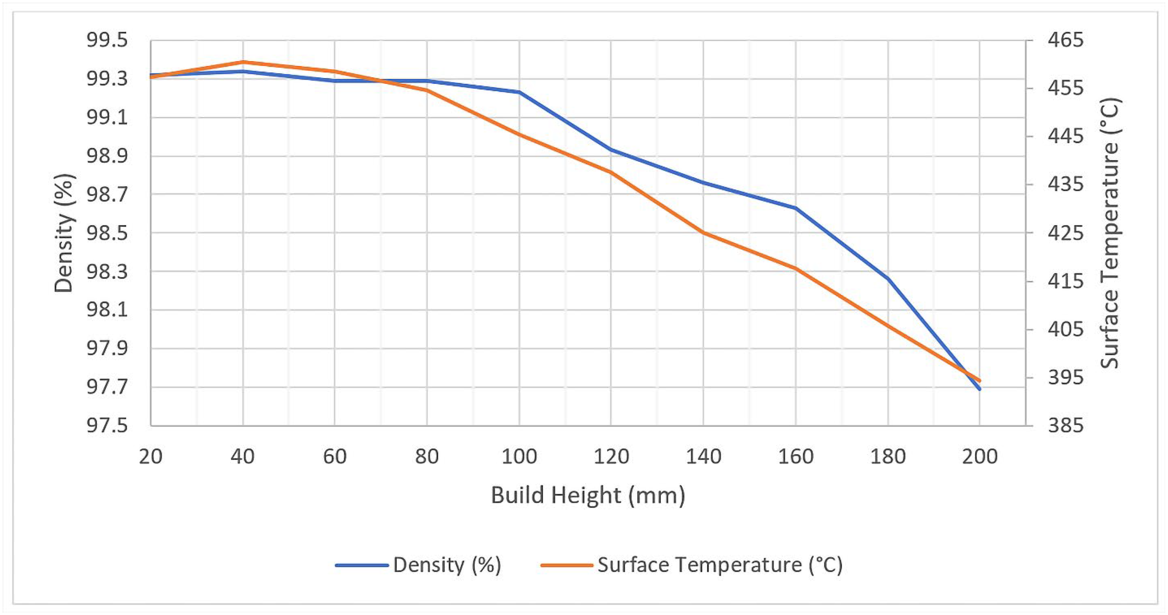
Molten Metal Jetting (MMJ) is an emerging metal additive manufacturing process that produces components via on-demand jetting of discrete droplets. This paper reports properties of T6 heat-treated AlSi7Mg alloy produced in different build orientations via MMJ. A Xerox ElemX machine was used to print AlSi7Mg coupons in horizontal, tilted, and vertical orientations. The aluminum feedstock was melted at 825 °C and was printed onto a 475 °C heated print bed using a jetting frequency of 400 Hz and a drop spacing of 500 μm. Coupons were heat treated to a T6 temper. The average yield strengths of heat-treated coupons in vertical and horizontal orientations were 240.4 ± 7.3 MPa and 244.6 ± 7.1 MPa respectively. This indicates that the vertical build orientation had minimal adverse effect on strength. However, average strain (11.5% ± 1.2% versus 14.6% ± 3.5%) values for the vertical and horizontal orientations, respectively, showed more pronounced effects. X-ray CT analysis of vertically oriented coupons revealed increases in porosity in material deposited above heights of ~90 mm. Above this build height, the measured surface temperature dropped below ~455 °C. External heating methods are therefore advised in order to maintain a surface temperature ≥ 455 ° and avoid excess porosity.

1. Introduction

Among the many advantages associated with metal additive manufacturing, two of the most often cited benefits are the ability to produce components without the need for tooling [1] and the ability to fabricate extremely complex geometries that enhance functional performance [2]. Up to this point in time, laser powder bed fusion (LPBF) has been the dominant metal AM (Additive Manufacturing) process, and industrial applications have primarily focused on aerospace components as well as custom biomedical implants [3]. It is not a coincidence that both application domains involve relatively low production quantities of high-value components.
Despite the impressive capabilities of LPBF, efforts to increase industrial adoption have been hampered by the extremely high cost of LPBF machines (often >$1M USD) [4], the cost of metal powders, which can be seven times or more the cost of bulk alloy in bar/rod form [5], and increasing concerns with environmental health and safety (EH&S) associated with metal powders [6]. Metal binder jetting can be an excellent alternative to LPBF for applications involving relatively small parts with intricate detail [7]. However, binder jetting has the same challenges as LPBF with regards to powder cost and EH&S concerns.
For metal AM to be adopted across a wider range of application domains, new AM process development is needed that targets (1) lower equipment costs, (2) alternatives to powder feedstock material, and (3) higher production speeds. There has been growing interest in metal AM processes that use wire, rod, or ingot feedstock materials rather than powder. One such process is Molten Metal Jetting (MMJ). Although early MMJ research activity dates to the 1990s and the pioneering work of Orme [8], it was not commercially introduced until Vader Systems released its MK1 machine in 2017. Xerox followed with its ElemX machine in 2021, and Grob introduced its GMP300 machine in 2022 [9]. The University of Nottingham has published research using an experimental MMJ machine produced by Canon/Océ [10]; however, that machine has not been commercially released as of yet. Several well-known AM companies have likewise been developing patent portfolios around MMJ [11,12]. The number of original equipment manufacturers pursuing this technology is indicative of the process’s considerable potential.
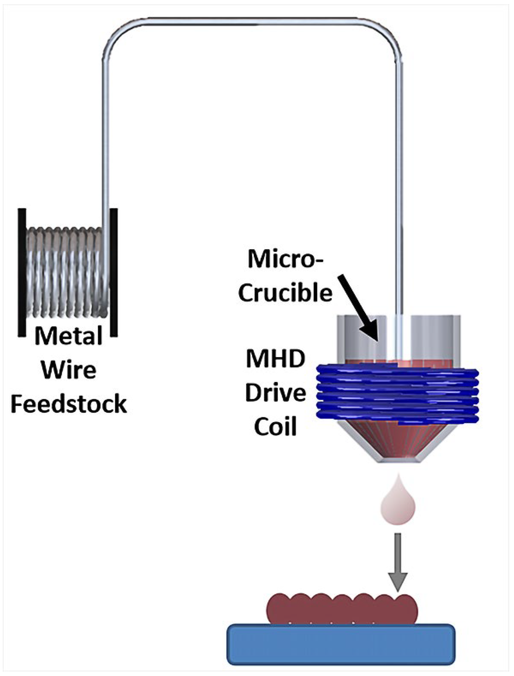
Figure 1 illustrates the basic setup of a typical MMJ process. Although there are numerous ways that molten metal droplet ejection can be actuated, most implementations of the process involve feeding metallic wire into a reservoir where it is melted and gravity fed towards a nozzle from which droplets are ejected on-demand. It is significant that the metal is melted before deposition with MMJ. This means that literally any alternative to metal powder feedstock, including ingot, rod, wire or pellets, can be used with an appropriately designed MMJ machine. This greatly reduces feedstock material cost as well as EH&S concerns. Droplet ejection may be actuated by pneumatic pulses [13], a vibrating piston [14], or magnetohydrodynamic (MHD) Lorenz forces [15,16,17]. Although many early MMJ publications focused on low-temperature alloys of tin [18], more recent research has focused on intermediate melting temperature alloys of aluminum [13] and copper [19,20]. The majority of published research focuses on either the physics of droplet ejection [21] or droplet impact, spreading, and solidification [22].
The overwhelming majority of published MMJ research to date has employed internally developed MMJ test rigs due to the lack of commercially available MMJ hardware. MMJ literature based on lab-built test rigs has provided foundational knowledge regarding the physics of molten metal droplet ejection, impact, spreading, and solidification. However, the significant differences in jetting hardware used in research labs has made it difficult for others to compare and/or replicate results. Furthermore, there is very little published work on the mechanical properties of widely-used aluminum alloys produced using commercially available MMJ equipment suitable for industrial use. Two recent exceptions include Kirchebner at al. [23] and Traxel et al. [24], which used the commercially available Xerox/ADDiTEC ElemX machine to print AlSi7Mg aluminum alloy material. Kirchebner et al. [23] studied the use of the ElemX machine for repair applications. More specifically, they machined pockets in aluminum bars, filled the pockets by jetting molten aluminum, and then studied the interface of jetted repair material with the surface of the component.
Traxel et al. [24] used an ElemX machine to fabricate coupons using different build plate temperatures and printing raster angle orientations. They then analyzed the mechanical properties, porosity, and microstructure of as-printed material. The authors comment that “Further precipitation heat treatment of this material may impart strength increases that bring the properties up to the full strength specification, but this is beyond the scope of the current work.”. This paper builds upon the published work of others by investigating the effects of part orientation and heat treatment on the mechanical properties, microstructure, and porosity of AlSi7Mg aluminum produced via the MMJ process.

2. Materials and Methods

2.1. Printer Setup

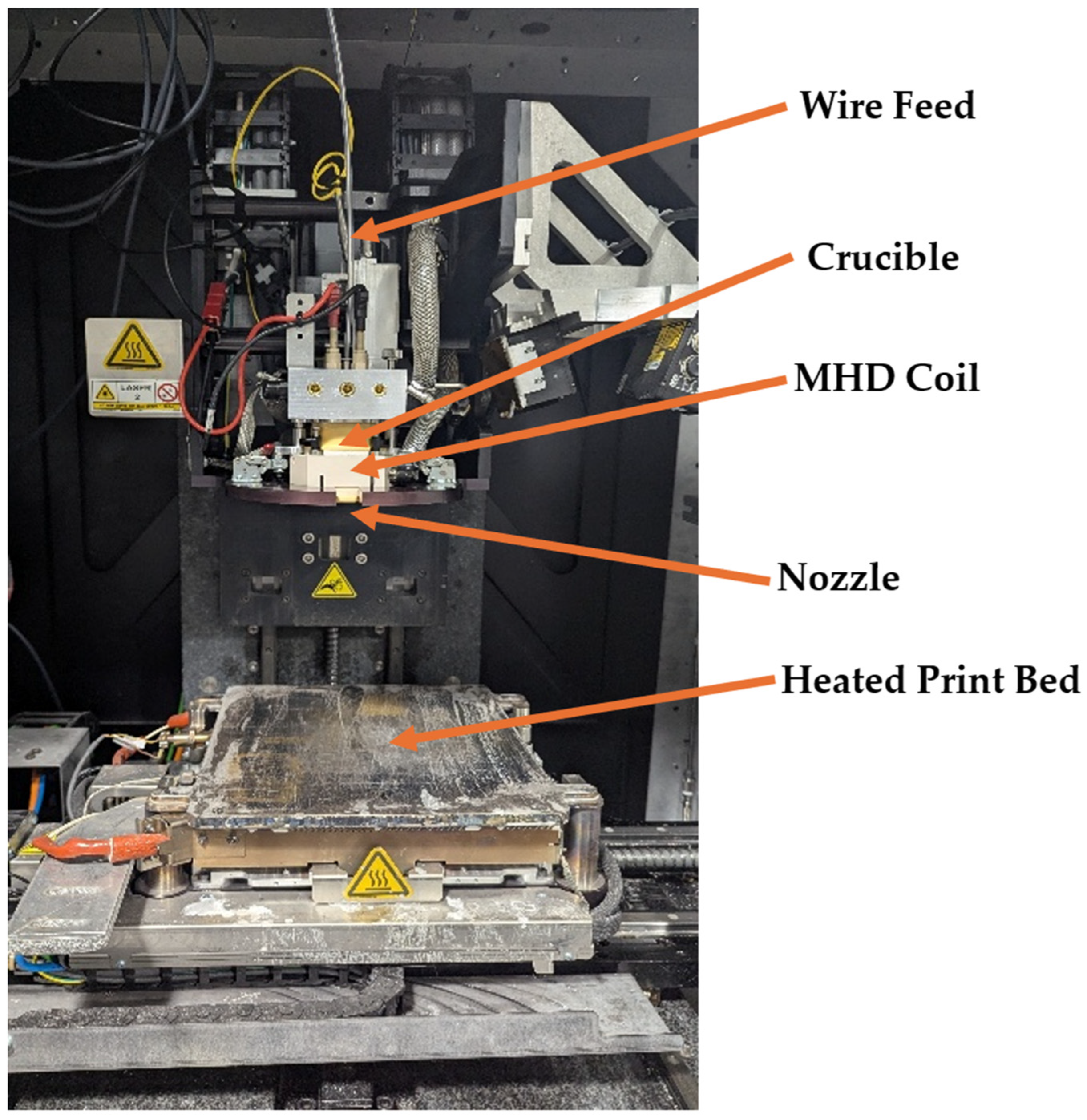
A Xerox/ADDiTEC ElemX Molten Metal Jetting machine (Figure 2) was used for all material deposition. This machine uses a 300 mm × 300 mm heated print bed that moves in the X-Y plane while droplets are ejected from a jetting assembly that is mounted on a Z-axis stage. A heated print bed temperature of 475 °C was used for all print trials. Graphite nozzles with a nominal orifice diameter of 500 µm were used to provide a good balance between feature resolution and print speed. Alcotec (Traverse City, MI, USA) AlSi7Mg aluminum alloy wire with a diameter of 1.52 mm was used as the feedstock material. The jetted aluminum drops were shielded by ultra-high-purity argon gas around the nozzle during printing. Other than the localized argon shielding around the nozzle, the machine was operated in an open atmosphere. Default printing conditions specified by the ElemX machine’s slicer software were used with the intention of producing orientation-specific heat-treated material properties of value to end users. Specifically, molten aluminum in the reservoir was maintained at a temperature of 825 °C. The droplet ejection frequency was set to 400 Hz, and the nominal center-to-center drop spacing was set to 500 µm.
For a given drop size, the layer thickness in MMJ is primarily a function of drop spacing within a line as well as spacing between adjacent tracks of material. For the nominal drop size produced with any given installed nozzle, layer thickness can be increased by reducing the center-to-center drop spacing and/or the distance between adjacent tracks. It can likewise be decreased by increasing the drop spacing and/or line spacing. The ElemX machine uses a z-height correction sub-system which pauses printing after every fifth layer to perform a 2D laser scan of the deposited material surface. The control software then makes minor adjustments in drop and line spacing for the subsequent 5 printed layers to compensate for minor deviations in z-height at each location on the part surface. This height correction system was used when printing all coupons used in this study.
During the build process, the top surface gets farther away from the heated print bed with each newly deposited layer. To assess the potential influence of surface temperature on porosity, microstructure, and mechanical properties, an Optris (Berlin, Germany) PI 640i thermal imaging camera was used to record surface temperature every 5th layer at the same time the layer height was being measured.

2.2. Build Geometries

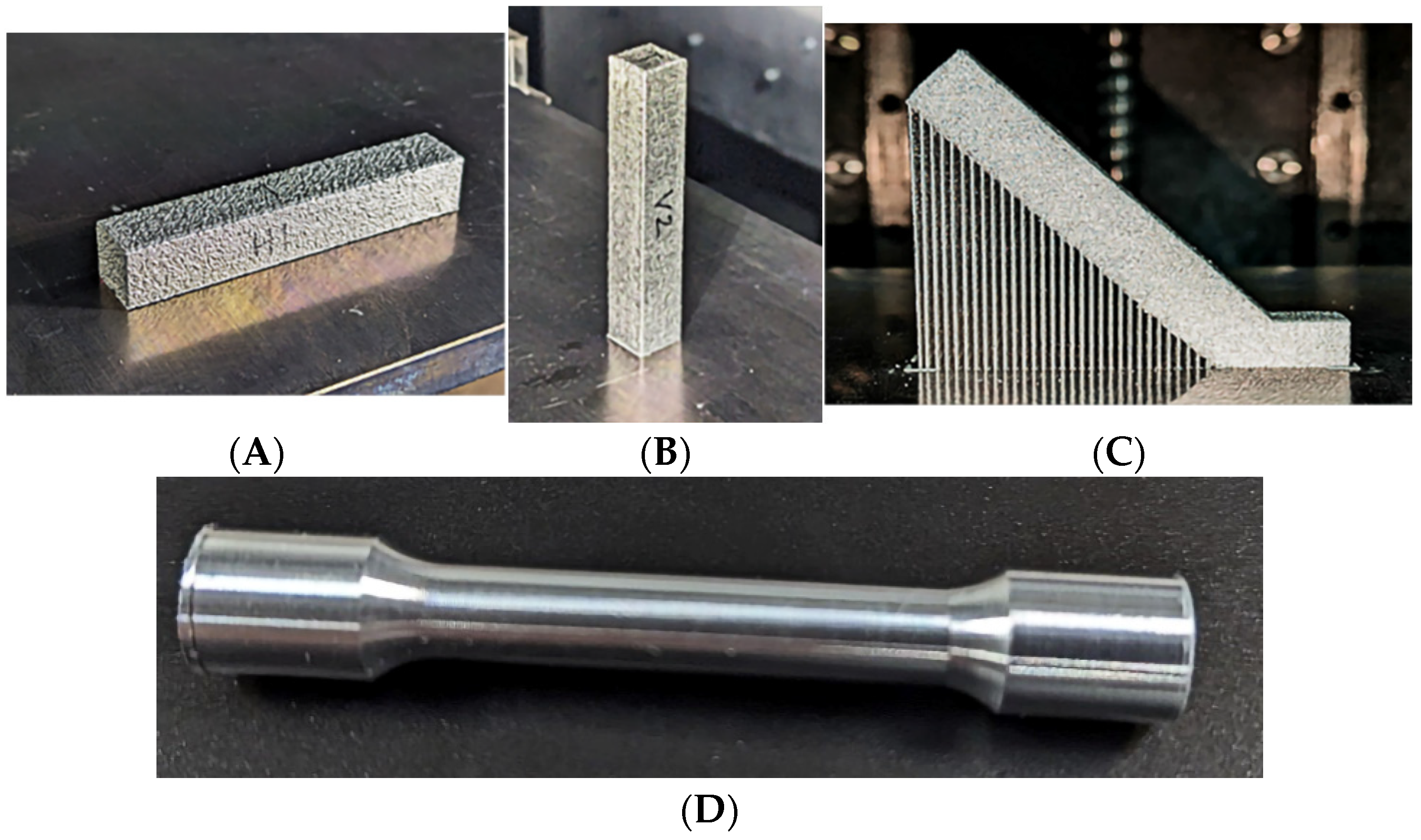
To compare mechanical properties of as-printed and heat-treated AlSi7Mg material using default jetting parameter values, rectangular blanks were printed at three different orientations. They were then machined to meet specifications for cylindrical ASTM E8 tensile bars. As shown in Figure 3A–C, coupons were printed with their longitudinal axes in the horizontal, vertical and inclined orientations. Each printed coupon was 75 mm long × 13 mm wide × 13 mm tall. Finish-machining of blanks resulted in cylindrical coupons having a 25.4 mm gauge length and a 6 mm reduced section diameter (Figure 3C). Note that in Figure 3C, a small horizontal section of material was added to the coupon to provide more intimate thermal contact with the print bed in the initial print layers.
A total of 30 tensile bars were printed for evaluation–15 bars to assess as-printed material properties, and 15 bars to assess heat-treated material properties. For each set of 15 bars, 5 bars were printed in each of the vertical, horizontal, and 45° inclined angle orientations. Each coupon was printed one at a time in the center of the build plate rather than in batches to provide the most uniform thermal conditions possible between parts in a given orientation. In addition to the tensile bar coupons, 200 mm tall 15 mm × 15 mm bars were printed with thermal imaging every 5th layer. The measured surface temperature as a function of part height was subsequently used with X-ray CT scan data to assess the effect of surface temperature on porosity.

2.3. Heat Treatment

Following printing, 5 coupons in each of the horizontal, inclined, and vertical build orientations were solution heat treated to a T6 temper to enhance their mechanical properties. The ASTM B917 standard practice for heat treatment of aluminum alloy was followed for the heat treatment. The bars were solution heat treated to 538 °C in a Lucifer convection furnace and held at that temperature for 4 h. Temperatures were continuously monitored using thermocouples positioned at five different locations within the furnace to ensure that the temperature fluctuation was within ±5 °C of the target value. Coupons were then quenched at room temperature within 10 s of removal from the furnace. Following quenching, the coupons were aged at 154 °C for 3 h. The aging process was initiated immediately after quenching.

2.4. Material Characterization

To prepare samples for microscopy, printed coupons were sectioned using an Allied (Cerritos, CA, USA) TechCut 5 water-cooled cutoff saw. Sectioned pieces were resin mounted and then progressively ground and polished to a 0.04 µm finish using a BUEHLER (Lake Bluff, IL, USA) AutoMet 250 polisher. Samples were etched in Weck’s reagent for 30 s and then rinsed with deionized water and 99% isopropyl alcohol. Optical microscopy was performed using a Hirox (Oradell, NJ, USA) KH-7700 optical microscope. Scanning electron microscopy with EDS was performed using a Tecscan (Brno, Czech Republic) VEGA 3.
Mechanical testing of heat-treated coupons was performed using an MTS (Eden Prairie, MN, USA) Criterion Model 43 electromechanical universal test system using a cross-head speed 0f 0.1759 mm/s. An MTS Advantage optical extensometer was used to measure and record elongation of the samples. Preliminary testing of as-printed coupons printed and machined under identical conditions was performed in an earlier study using a Pasco (Roseville, CA, USA) ME-8236 material-testing machine at the same 0.1759 mm/s cross-head speed; however, the optical extensometer was not used in those preliminary tests. Elongation values were determined for these coupons via caliper measurement.
Porosity analysis as a function of distance from the heated build plate was performed by X-ray CT scanning the 200 mm tall porosity determination bars. A Pinnacle (Duluth, GA, USA) X-ray Solutions PiXS-225/60 cone-beam X-ray computed tomography (XCT) system was used to scan and evaluate one tensile specimen from each build direction (total of three). Scans were performed at a voltage of 160 kV and a current of 250 µA, with the power not exceeding 40 W. A total of 720 projections were acquired over a full 360° rotation with an angular increment of 0.5°. Sixteen frames were averaged per projection. The source-to-object distance (SOD) and source-to-detector distance (SDD) were 120 mm and 1000 mm, respectively, resulting in a geometric magnification of 8.33X. The detector pixel pitch was 100 µm, corresponding to a voxel size of approximately 12 µm. Reconstruction of the projection data was performed using Volume Graphics VGSTUDIO MAX (v2023.3) software. The Shepp–Logan reconstruction filter was applied during the filtering stage of the filtered back projection (FBP) process. Ring artifact reduction and beam hardening correction were applied during reconstruction to minimize artifacts. To eliminate noise-related artifacts, only pores exceeding eight voxels were included in the porosity analysis. The total specimen volume was obtained using the classic surface determination method. Total porosity was calculated as the ratio of segmented pore volume to total specimen volume. Porosity was measured along the Z-axis of the 200mm tall part at 20 mm intervals (i.e., Z = 0 to 20mm, Z = 20 to 40 mm, etc.).
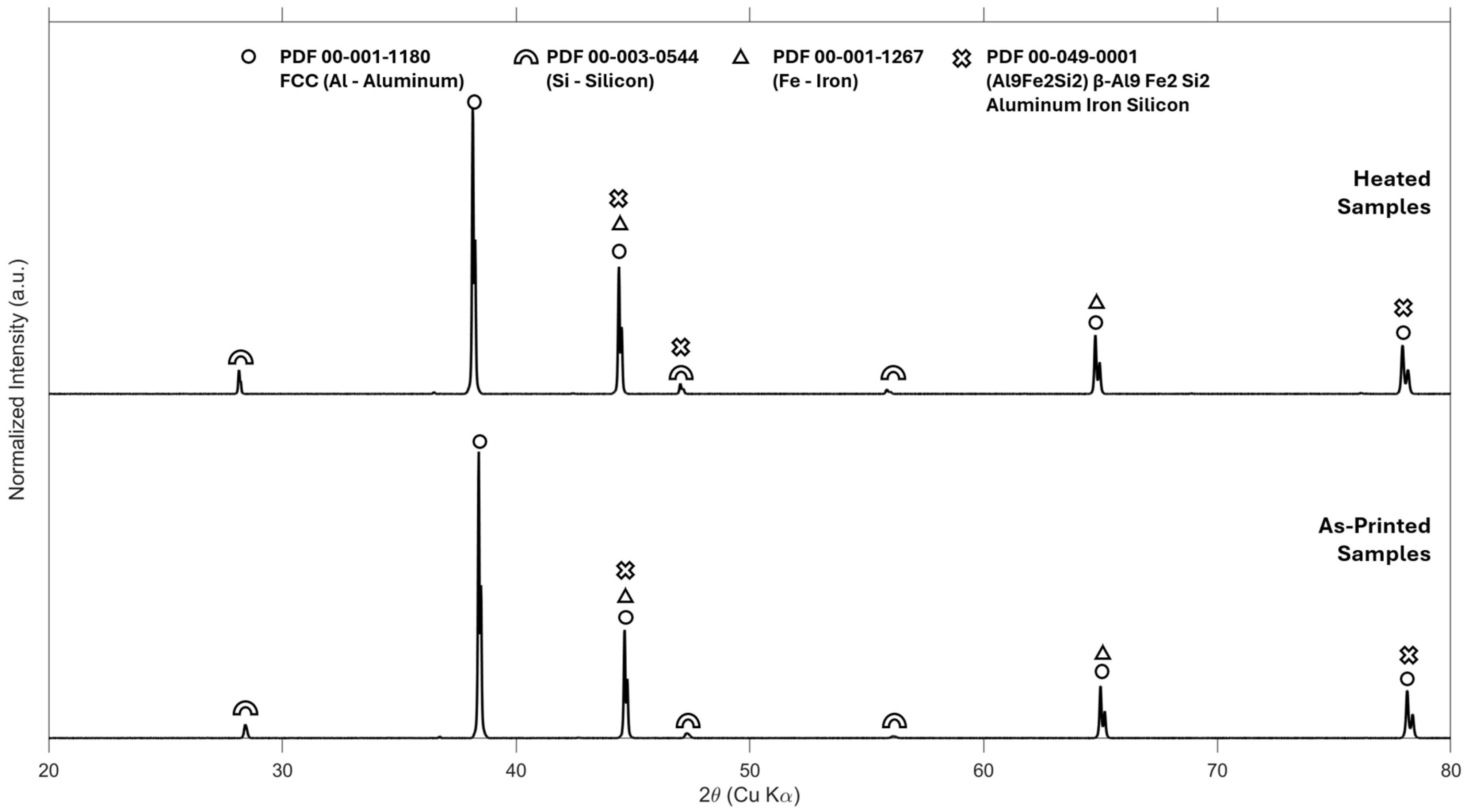
Phase identification of the samples was performed using X-ray diffraction (XRD) with a D8 Discover diffractometer (Bruker Corporation, Billerica, MA, USA) equipped with a Cu Kα radiation source (λ = 1.5418 Å) and a LYNXEYE XE-T detector operating in 1D mode. Diffraction patterns were collected using a coupled θ–2θ geometry in continuous PSD fast-scanning mode. Measurements were carried out over a 2θ range of 5–80° with a step increment of approximately 0.015° and a time per step of 0.1 s, resulting in a total acquisition time of approximately 10 min per scan. The X-ray generator was operated at an accelerating voltage of 40 kV and a current of 40 mA. The incident beam optics consisted of a motorized primary slit with a width of 0.6 mm and a secondary slit with a width of 5.0 mm. All measurements were conducted at room temperature. Diffraction patterns were processed and analyzed to identify crystalline phases present in the samples.

3. Results

3.1. Tensile Test Results

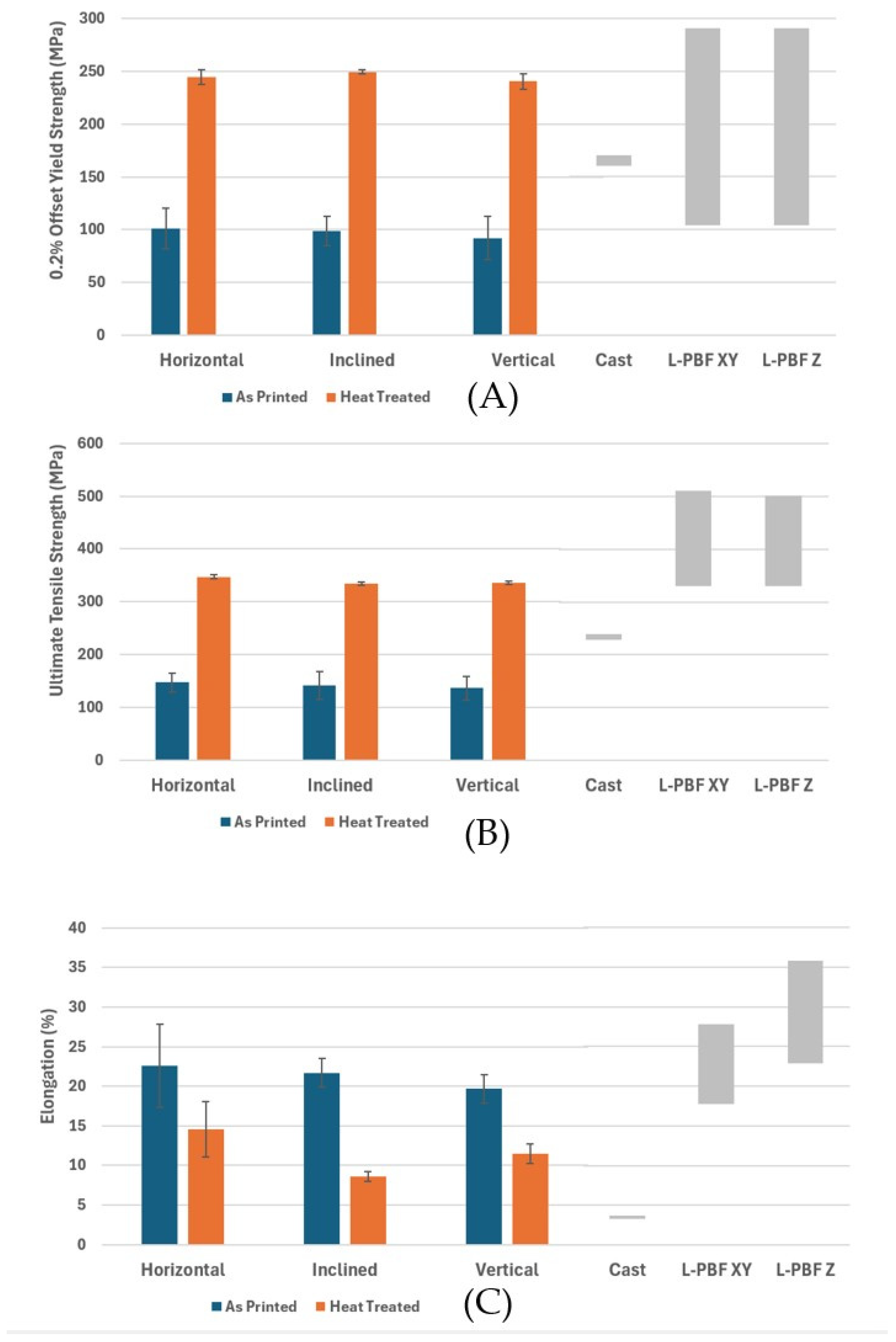
For both as-printed and heat-treated conditions, ultimate tensile strength (UTS), yield strength (YS), tensile modulus, and elongation at break were measured for each of the five samples printed in the horizontal, vertical, and inclined orientations. Figure 4 summarizes the results. The heat-treated 0.2% offset YS and UTS values show relatively small sensitivity to part orientation. Specifically, heat-treated YS value coupons built in the inclined, and vertical orientations are within 2% of those built in the horizontal orientation, while the heat-treated UTS values for inclined and vertical coupons are within 4% of the horizontal values.
When comparing as-printed and heat-treated strength properties, heat treating increased the YS of horizontal, inclined, and vertical coupons by 141.9%, 152.3%, and 161.3%, respectively (Figure 4A). Likewise, heat treating increased UTS by 136.0%, 135.9%, and 146.3% in those respective orientations (Figure 4B). The error bars in Figure 4A,B also show that heat treating significantly reduced variability. The increased strength comes with a significant loss of ductility, as shown in Figure 4C. Specifically, elongation of horizontal and vertical coupons drops by 35.4% and 60.4% respectively.
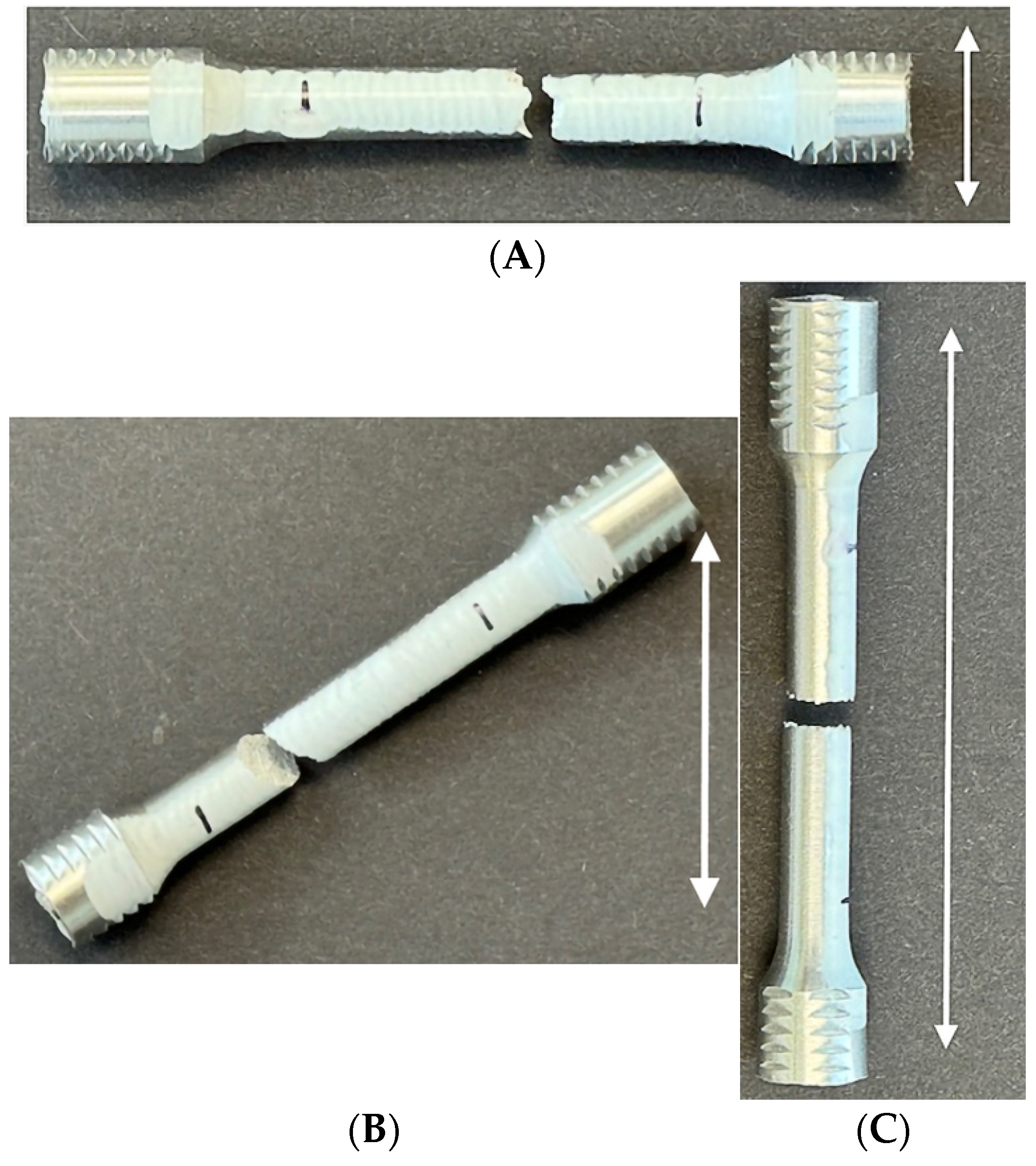
Figure 5 shows images of heat-treated tensile coupons printed in the horizontal, inclined, and vertical orientations following testing. The white arrows in Figure 5A–C) denote the Z-axis build direction for each coupon. For coupons fabricated in the horizontal orientation (Figure 5A), the build direction (Z-axis) is perpendicular to the tensile axis. Instead of fracturing at layerwise interfaces, fractures occurred across the stack of layers. The jagged fracture surface reveals the cross-section of layers rather than droplets and print tracks within a layer. For coupons fabricated in the 45° inclined orientation (Figure 5B), the tensile axis is oriented 45° with respect to the vertical build direction of the coupons. The fracture surfaces in these coupons are quite flat and have a 45° sloped orientation with respect to the tensile axis. This indicates that these coupons cleanly fractured at an interlayer interface. Coupons built in the upright vertical orientation (Figure 5C) likewise had flat fracture surfaces perpendicular to the tensile axis of the coupons. The tensile axis for the vertical coupons is parallel to the Z-axis print orientation, thus the flat fracture surfaces correspond to layerwise interfaces.
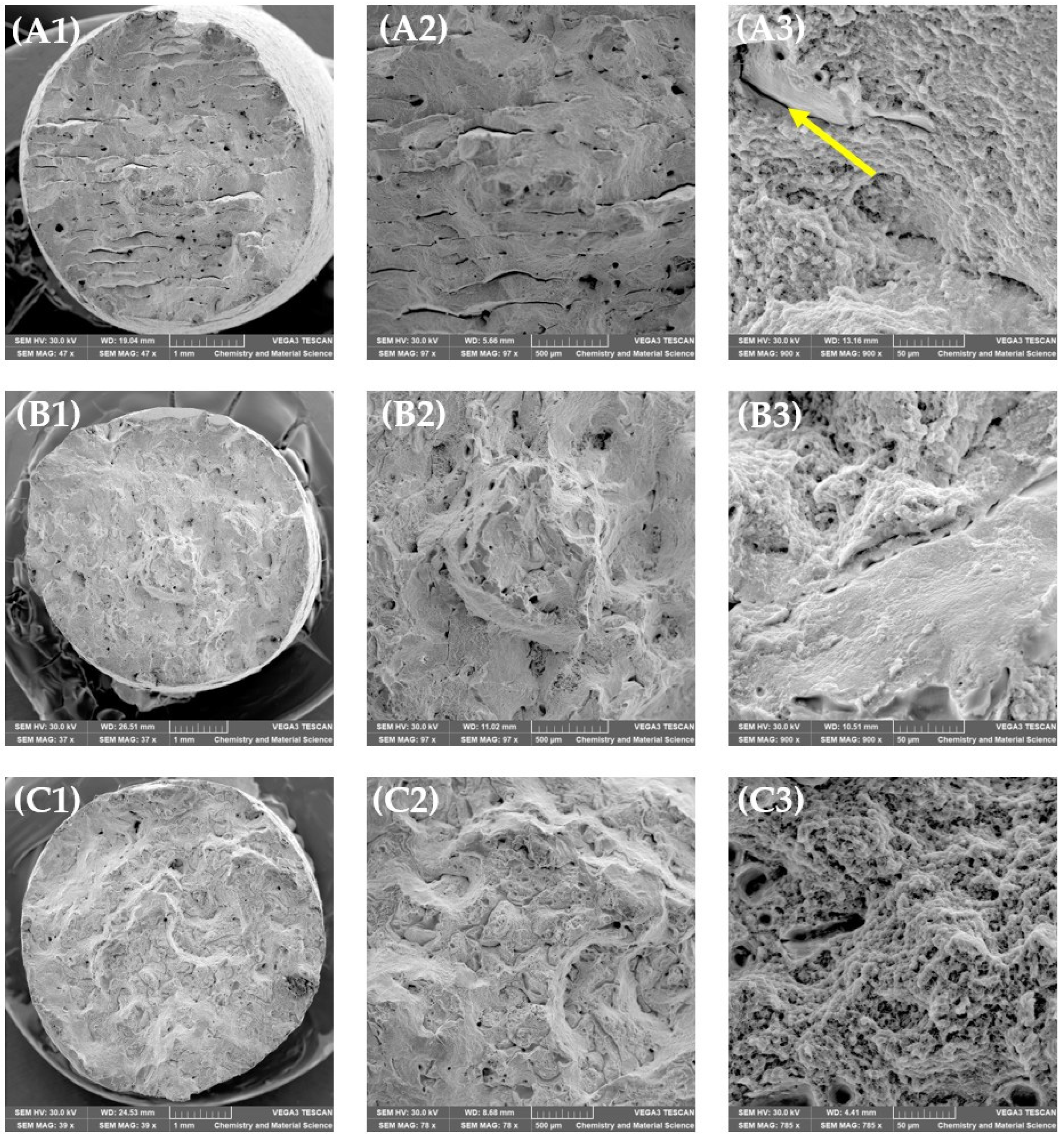
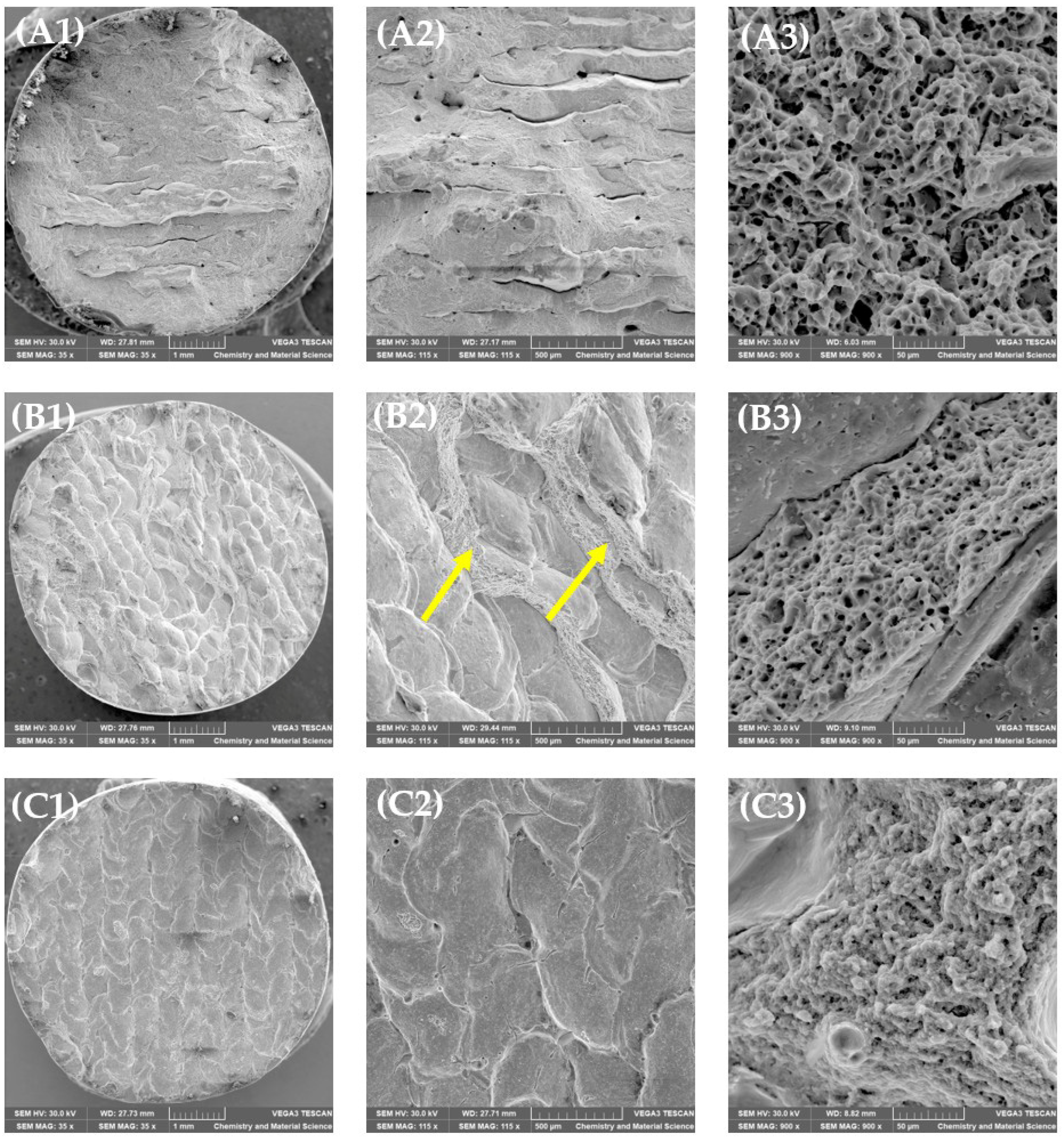
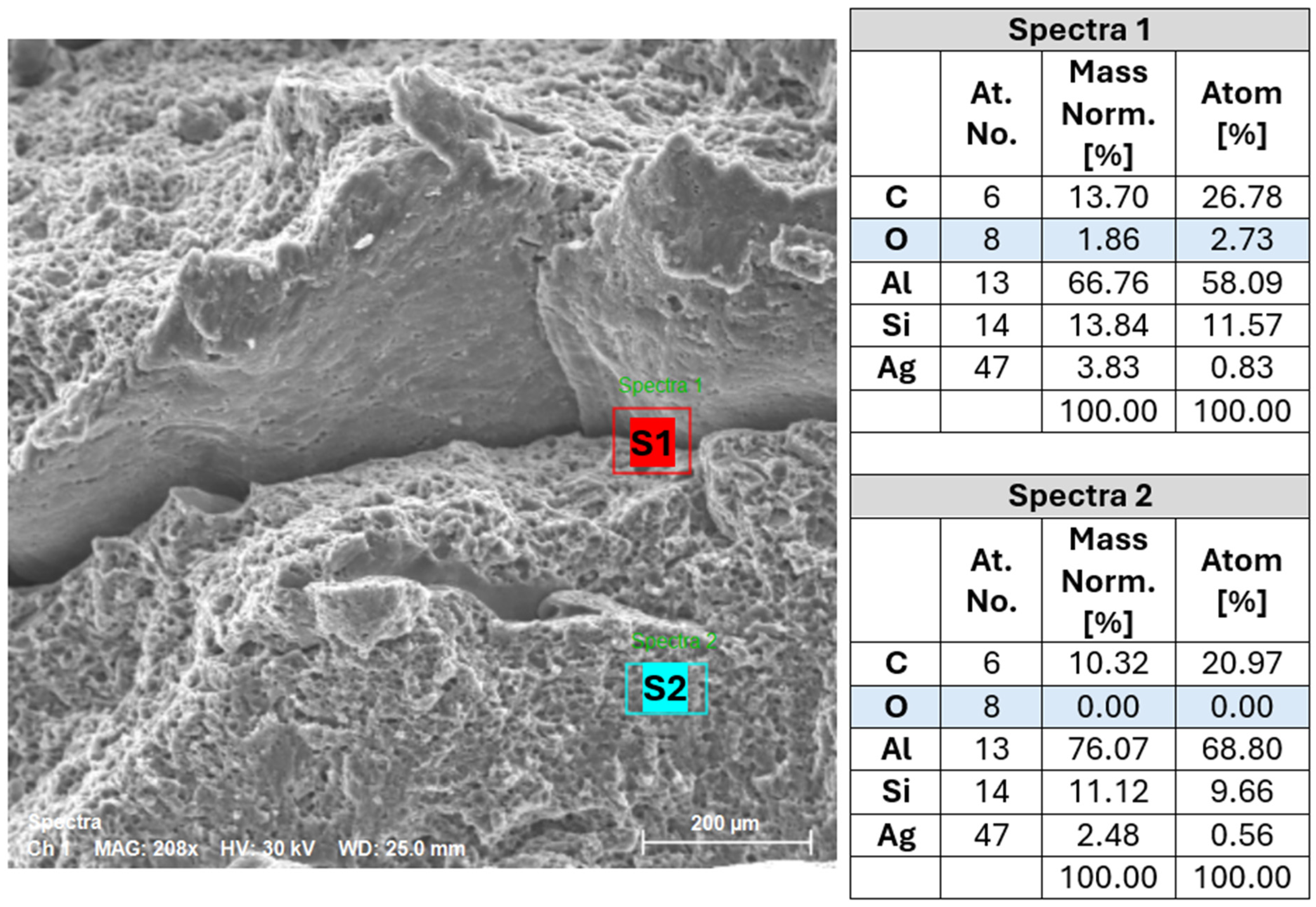
Analysis of the fracture surfaces of as-printed (Figure 6) and heat-treated (Figure 7) coupons fabricated in each orientation reveal substantial differences. Comparing Figure 6(A1) with Figure 7(A1), the as-printed horizontal coupon showed more of a propensity to delaminate at the layer interfaces near the elongated fracture surface than the heat-treated sample. A comparison of Figure 6(B1) with Figure 7(B1) and Figure 6(C1) with Figure 7(C1) shows pronounced differences in failure of the inclined and vertical coupons before and after heat treatment. The plainly visible oval shapes in Figure 7(B1,B2,C1,C2) (heat-treated condition) correspond to splat patterns formed by molten metal droplets at interlayer boundaries during printing. Unlike the uniform distribution of ~5 μm dimples in the horizontal coupon fracture surfaces, Figure 7(B2,C2) show only small isolated areas of dimpling, highlighted by the yellow arrows. The majority of the fracture surface areas consist of almost undisturbed droplet splats. This indicates brittle fracture at the droplet interlayer boundary and is consistent with lower heat-treated material elongation values recorded in Figure 4C. In contrast to the heat-treated inclined and vertical fracture surfaces, the as-printed inclined and vertical fracture surfaces in Figure 6(B1–B3,C1–C3) show a mix of dimpled and semi-smooth surfaces. These samples have elongated to some extent at the interlayer boundary before failure, and droplet splat patterns like those in Figure 7(B1–B3,C1–C3) are not plainly evident in Figure 6. The Xerox ElemX machine used in this study only uses local argon shielding around the droplets being deposited. As the print bed moves in the X–Y plane during printing, the heated top surface of each layer is exposed to open atmosphere, thus promoting conditions favorable to oxide formation at the interlayer boundaries. The elemental composition analysis presented in Figure 8 supports this hypothesis by showing oxygen pickup at a layer interface, while no oxygen is seen in the region within a layer. Where present, the strong, but brittle, oxide film will contribute to the loss of ductility in the inclined and vertical coupons that fracture along the interlayer boundaries. Future research could involve performing MMJ deposition in a fully controlled argon atmosphere. Despite the clean separation of inclined and vertical coupons at layer interfaces, the fact that the YS and UTS values of coupons fabricated in the heat-treated inclined and vertical orientations are within 4% of values for the horizontally oriented coupons indicates strong bonding at the layer interface.

3.2. Porosity Analysis

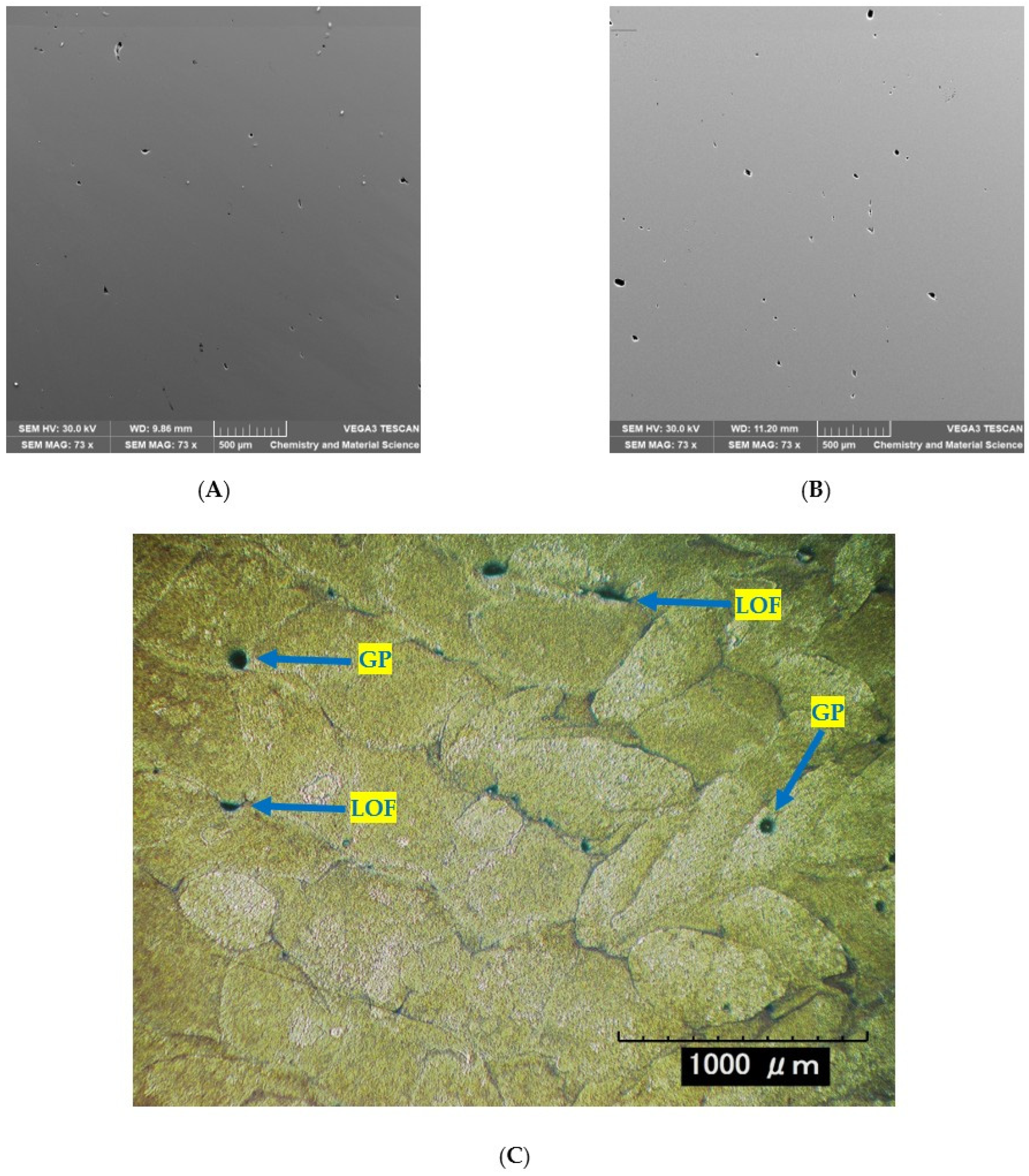
As described in Section 2, Volume Graphics was used to characterize porosity in the X-ray CT scan data. Figure 9A,B show representative low magnification micrographs from horizontal coupons in the as-printed and heat-treated conditions. These images provide a qualitative impression of the size and distribution of pores. Figure 9C shows a low magnification etched optical micrograph in which boundaries between droplets can be seen. Irregularly shaped pores resulting from lack of fusion typically appear at corners where multiple droplets meet, whereas spherical gas induced porosity can appear anywhere within the sample. The lack of fusion pores tend to be relatively large (>100 μm in length) whereas gas pores tend to be <100 μm in diameter. Lack of fusion in MMJ can be caused by pockets of trapped gas between partially overlapping droplets as they spread and solidify, or it can be caused when the substrate is cool enough that the droplets solidify before they are able to fully flow out and fill voids with previously deposited material. Both cast aluminum and aluminum produced via L-PBF can exhibit irregular and spherical shaped pores, but for different reasons. Very large irregular pores in castings can result from trapped gases caused by turbulent flow during pouring or by shrinkage porosity in thick sections, while irregular pores in L-PBF material can be the result of lack of fusion between spherical particles during laser melting or keyhole defects. Both casting and L-PBF can have spherical pores from dissolved gases that are insoluble with solidified aluminum (e.g., hydrogen). In L-PBF, those pores can be present within the metal powder particles, or they can form as dissolved gases come out of the solution during solidification.
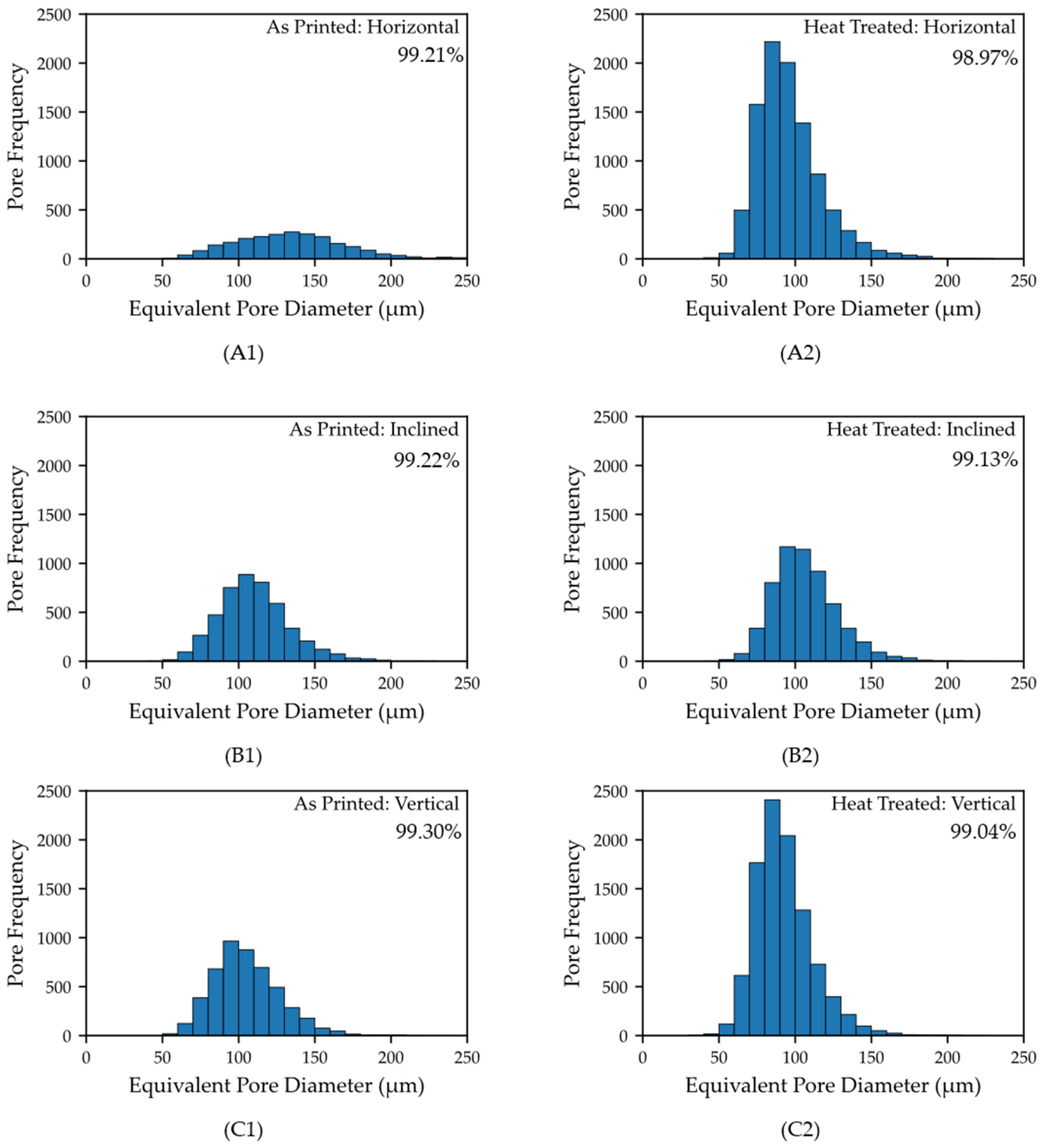
Figure 10 provides pore size histograms for horizontal, inclined, and vertical coupons in the as-printed and heat-treated conditions. The exact same coupons were X-ray CT scanned before and after heat treatment to provide a direct comparison of the effect that heat treatment has on porosity. The overall sample densities are provided in the upper right corner of each chart. The general trend is that heat treatment resulted in an increase in the absolute numbers of pores, but a slight decrease in average pore sizes. This combination resulted in a modest reduction in overall sample density following heat treatment.
It is well known that hydrogen has high solubility in molten aluminum and low solubility in solid aluminum. That can lead to the evolution of hydrogen micropores during solidification [27]. In wire-arc additive manufacturing (WAAM), residual hydrocarbon lubricants on wire feedstock from the drawing process can serve as a source of hydrogen that leads to microporosity. Hauser et al. [28] observed higher levels of hydrogen microporosity when the flow rate of argon shielding gas was increased. The authors hypothesized that as cooling rate increases, hydrogen bubbles have insufficient time to escape the surface prior to solidification. The MMJ process used here is similar, in the sense that a local flow of argon shielding gas is used around the deposited material. When samples are subsequently heat treated, hydrogen micropores can grow into larger pores via Ostwald ripening or micropore migration and coalescence [29]. The coalescence of micropores smaller than the detection limit of the X-ray CT scanner used here into larger pores may explain the increased pore count following heat treatment. The slight leftward shift in the pore size distribution following heat treatment is potentially attributable to some healing of slender lack of fusion pores and/or shrinkage during rapid quenching following heat treatment.
Among the three build orientations, coupons built in the vertical orientation have an overall build height of 75 mm. Components, such as replacements for sand castings, can often have build heights greater than 75 mm. When the print bed temperature is held constant, the surface temperature of the top layer temperature is expected to decrease as the part grows taller (i.e., with each successive printed layer, the distance between that layer and the heated print bed increases). It is therefore reasonable to consider whether the porosity/density of material changes as a function of surface temperature. The relation between build height, top surface temperature and porosity was therefore investigated using thermal imaging and X-ray CT scanning. As previously described, surface temperature measurements were recorded every 5th layer during printing of the horizontal, inclined, and vertical coupons as well as during printing of a 200 mm tall bar. Following printing, the 200 mm tall bar was also X-ray CT scanned. The resulting scan data was digitally divided into ten segments, each measuring 20 mm tall. The density of each 20 mm tall segment was then separately quantified.
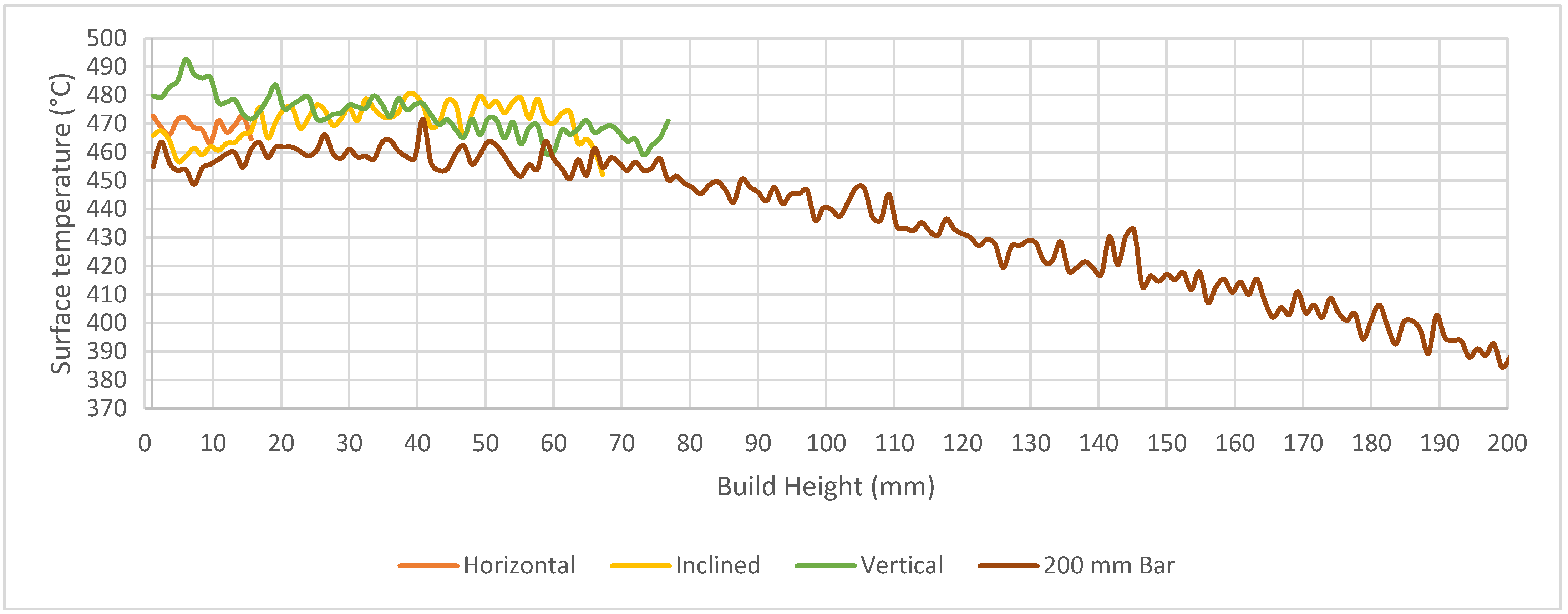
Figure 11 plots the unsmoothed measured temperature for tensile bars in each orientation as well as the 200 mm tall bar as a function of build height. As a practical matter, the print bed temperature set point value on the machine controller was 475 °C, whereas the measured temperature on the top surface of the print bed could be as much as 50 °C lower than the set point value due to the location of the print bed thermocouple. During printing, horizontal, inclined, and vertical coupons have cross-section coupon areas of 975 mm2, 239 mm2, and 169 mm2, respectively. However, the average surface temperature during the fabrication of horizontal, inclined, and vertical coupons held reasonably steady through their builds despite significant differences in overall surface area.
The surface temperature of the 200 mm tall coupon likewise holds reasonably steady up to a build height of approximately 75 mm before it starts to decline almost linearly with increasing distance from the heated print bed. Figure 12 plots density from CT scan data for each of the 20 mm segments of build height together with the corresponding average measured surface temperature. Above approximately 80 mm of build height, the reduction in density follows the reduction in surface temperature reasonably closely.

3.3. Microstructure

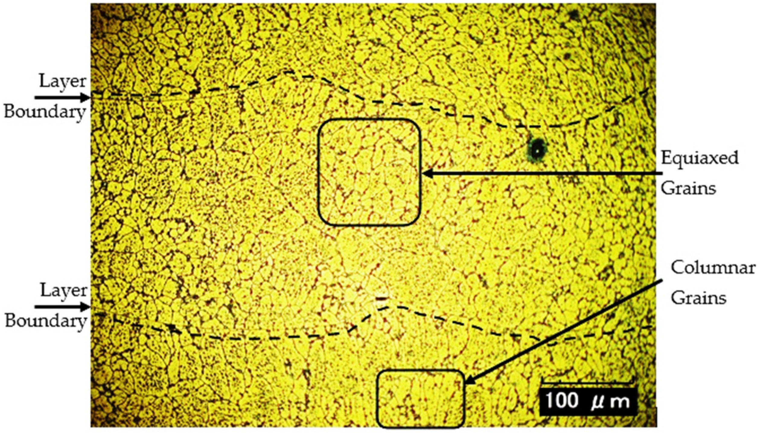
Optical micrographs of the printed parts were captured in both the as-printed and heat-treated (T6) conditions. Figure 13 shows a transverse view of heat-treated material along with feature annotations. The black dashed lines are offset a small amount from boundaries at the layer interfaces to improve visibility. The scalloped shape of the interlayer boundary corresponds to the overlapping portions of individual droplets following solidification. The microstructure consists primarily of equiaxed grains with some localized regions of columns. The equiaxed grains are on the order of 30–50 μm in size.
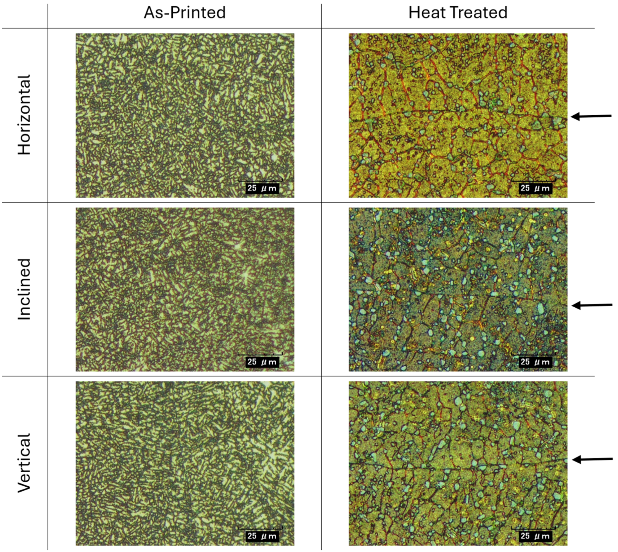
Figure 14 provides a comparison of microstructure before and after heat treatment for samples built in all three orientations. The as-printed microstructures (left column) have uniform dendritic α-Al dendrites whose size and spacing are consistent with rapidly cooled cast A356.0-T6 alloy. Micrographs of the heat-treated material from each build orientation (right column) were carefully chosen to include a horizontal droplet boundary indicated by arrows. All three micrographs have similar appearances primarily consisting of equiaxed α-Al grains having a dispersion of silicon particles. Larger ~5 μm diameter silicon particles accumulate along the grain boundaries, while smaller ~1 μm diameter silicon particles form inside the grain boundaries. Given the very similar microstructure seen across the three build orientations, each of which had a significantly different printed cross-sectional area, the relative insensitivity of YS and UTS between the samples is to be expected.
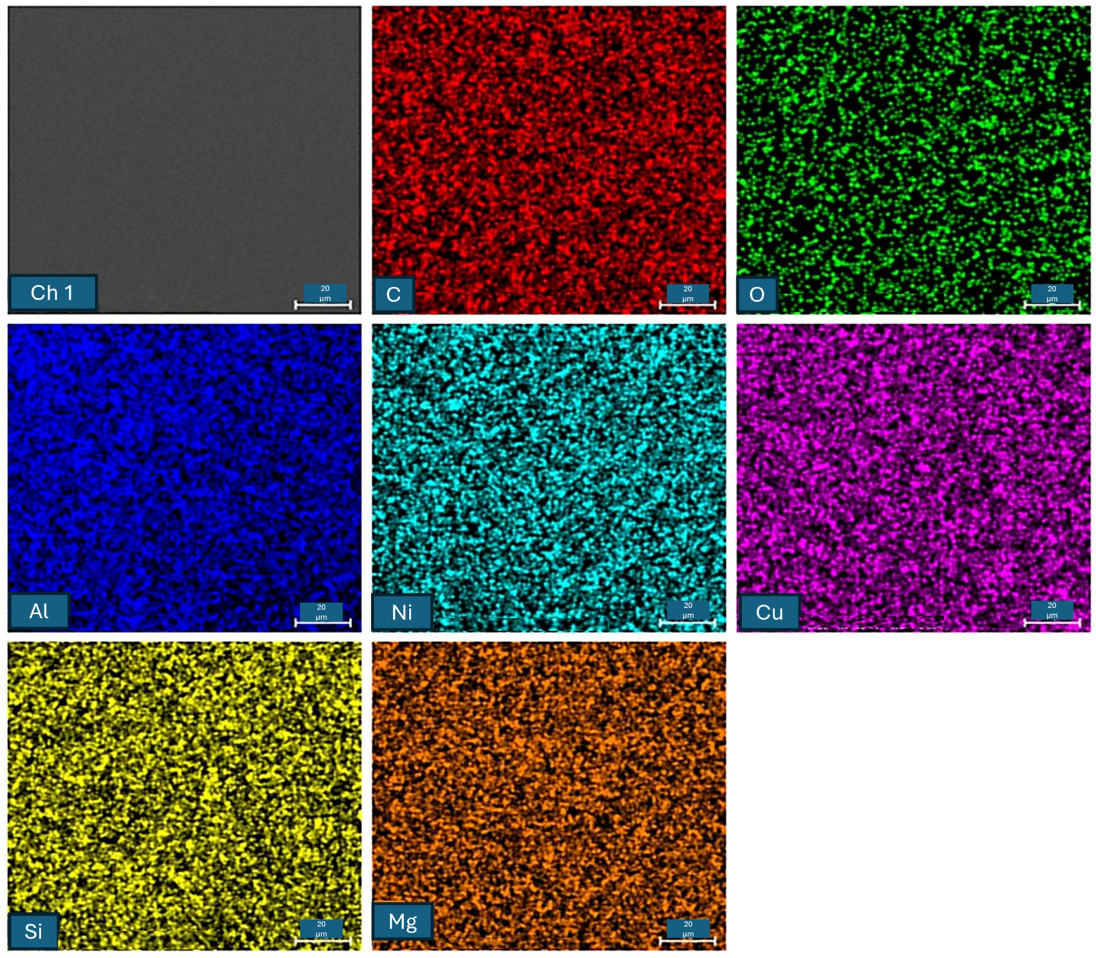
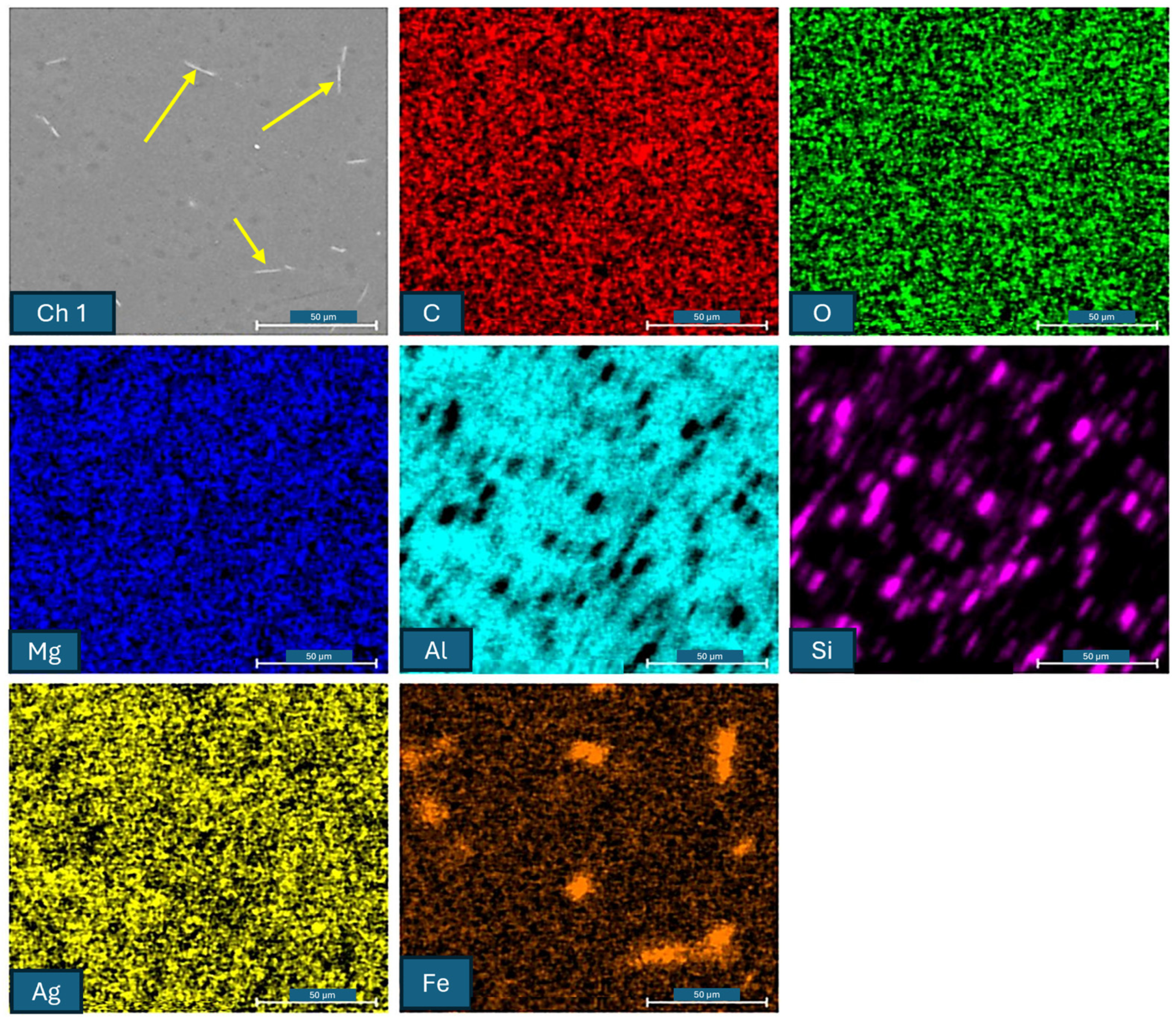
Figure 15 and Figure 16 display EDS analyses of as-printed and heat-treated samples respectively. Figure 16 confirms the formation of silicon particles following the T6 heat treatment. In addition to the silicon particles, a small number of AlFeSi needles are also observed in the heat-treated samples. These are readily identifiable in the Fe panel in Figure 16.
Figure 17 shows normalized XRD plots for as-printed and heat-treated samples. Both samples show identical peaks with comparable amplitudes for FCC Al as well as Si. The presence of Al9Fe2Si2 is consistent with the Fe EDS signature in Figure 16.

4. Discussion

AlSi7Mg is chemically similar to A356.0-T6 sand-casting alloy, hence MMJ or other metal AM processes using AlSi7Mg are potential alternatives to sand casting. Sand casting is a labor-intensive process; however, it has very low material feedstock cost (ingot) and relatively low equipment requirements relative to metal AM processes. Metal AM processes can lower labor content, although the cost of powder and machine hardware can be quite high. MMJ is worth considering, however, due to its much lower feedstock costs. The YS, UTS, and elongation values plotted in Figure 4 includes dashed lines showing handbook expected values for sand-cast A356.0-T6 material [25]. The A356.0-T6 (heat-treated) cast material specifications for YS and UTS fall midway between the as-printed and heat-treated MMJ values, regardless of MMJ build orientation, suggesting that heat treatment of MMJ parts is needed if MMJ AlSi7Mg is to be considered as an alternative to sand-cast A356.0-T6 components. The elongation value for as-printed or heat-treated MMJ material is well above the elongation value of cast A356.0-T6, hence elongation is not a concern when considering MMJ as an alternative to casting. The low solidification rate, columnar microstructure, and high porosity that are characteristic of sand-cast aluminum explain the significantly better mechanical properties associated with the heat-treated MMJ material, regardless of build orientation.
AlSi7Mg has been fabricated via the laser powder bed fusion (L-PBF) process, hence a comparison of MMJ and L-PBF results is of value. Medrano et al. [26] published a comprehensive study of L-PBF-fabricated AlSi7Mg properties in both as-printed and T6 heat-treated conditions with multiple aging schedules at combinations of time (0, 100, and 1000 h) and temperatures (140 °C and 177 °C). Although this MMJ manuscript is not a study of heat treatment conditions on mechanical properties, there is instructive value in seeing where YS, UTS, and elongation values with this MMJ study fall within the range of values that Medrano et al. reported. Figure 4 includes the min/max ranges of measured YS, UTS, and elongation using different aging schedules from Medrano’s L-PBF study with an EOS M290 machine. Tensile coupons were printed in the XY (i.e., horizontal) and Z (vertical) orientations prior to heat treatment. While the YS values of MMJ material aged at 154 °C for 3 h fall in the upper half of YS values found in the L-PBF material across different aging profiles, the UTS and elongation values of MMJ material landed at the bottom of the corresponding ranges of L-PBF material results. The MMJ aging cycle of 154 °C for 3 h may be more practical from an industrial throughput perspective; however, the significant gain in UTS from the longer (100–1000 h) aging cycles suggests that future in-depth studies of aging conditions on the properties of MMJ material may produce valuable improvements in UTS if called for by the end-use application. Extending those studies to include fatigue life would likewise be an opportunity for future research.
Regarding the relationship between density and surface temperature, a lower temperature at the top surface can contribute to a lack of remelting when droplets land on previously deposited material. Thermal imaging of horizontal, inclined, and vertical coupons during fabrication at build heights below 75 mm revealed relatively steady temperatures regardless of the significant differences in overall surface area. As build height increases beyond 75–80 mm, however, conductive and convective heat losses become prominent relative to build platform heating. The lower temperature of the top surface means that the droplets solidify more quickly than droplets landing on layers with higher temperatures. Droplets that solidify before they can fully flow out and eliminate gaps may explain the increase in porosity of printed material more than ~90 mm from the heated bed. Although Traxel et al. [24] did not study the effect of build height on surface temperature, they did report that porosity increased significantly in parts fabricated at lower print bed temperatures. It is relatively straightforward to impart additional heat to the surfaces of components via radiative heating, induction heating, or lasers to ensure high-density material at build heights above ~80 mm. Zope et al. [30] have investigated convective heat transfer with MMJ, however, much work remains to be done studying part-level heat transfer of arbitrary geometries with this relatively new process.
The MMJ process is still at an early stage of maturity; however, this study demonstrates the potential to produce reasonably dense (99+%) material with heat-treated properties that easily exceed those of cast A356.0-T6. Furthermore, recent work has demonstrated the feasibility of scaling up the process using independently controllable multi-nozzle arrays [31] in which material deposition rate scales up without adversely affecting achievable feature size. Deposition of molten metal from an array of nozzles will likewise increase the heat flux and could potentially reduce or eliminate the need for external heating to maintain critical surface temperature at build heights > 80 mm.

5. Conclusions and Future Directions

AlSi7Mg alloy was deposited using Molten Metal Jetting to produce coupons in horizontal, inclined, and vertical orientations. Following T6 heat treatment, mechanical properties, density, and microstructure were assessed and compared with those of as-printed material. Highlights of the work are summarized as follows:
  • Heat treatment resulted in YS values in horizontal, inclined, and vertical orientations of 244.6 ± 7.1 MPa, 249.3 ± 2.1 MPa, and 240.4 ± 7.3 MPa respectively, corresponding to a ~150% increase over as-printed values. Likewise, UTS values in those orientations were 346.9 ± 3.7MPa, 333.8 ± 3.0 MPa, and 335.7 ± 2.6 MPa respectively, corresponding to a ~140% increase over as-printed values.
  • Although porosity was generally less than 1% across sample geometries, an increase in porosity closely tracked decreasing surface temperatures below ~455 °C. Surface temperature was reasonably steady at build heights below 75 mm, regardless of printed surface area. This suggests the need to employ external heating methods to maintain a critical surface temperature above ~455 °C at build heights > 75 mm.
  • Heat treatment increased overall porosity by 0.24%, 0.09%, and 0.26% in the horizontal, inclined, and vertical orientations, respectively, while the equivalent pore size slightly decreased.
  • Future Directions: As MMJ is a relatively new process, many potential research directions are available to pursue.
  • Closed-loop feedback control: Based on the nominal 500 μm drop diameter in this work, 15,279 droplets must be printed per cm3 of part volume. Given the large number of droplets needed to print each part, process drift involving drop size and/or velocity can significantly impact dimensional accuracy and surface finish. Real-time measurement of drop size and velocity coupled with process parameter correction is therefore a high-priority research opportunity.
  • Large part manufacturing: With closed-loop feedback control, future multi-nozzle-array MMJ systems could also be used to print physically large components at high material deposition rates while maintaining the ability to produce relatively fine features due to the small droplet sizes of each nozzle.
  • Support-free printing: Support removal is a major limitation of many metal AM processes. It is possible to produce sloped down-facing surfaces with MMJ down to approximately 40 degrees. Because there is no powder bed, unsupported down-faced surfaces can theoretically be printed using 5-axis motion stages that tilt the part during printing. Advanced slicing and motion-control research is needed to enable support-free metal AM printing.
  • Non-weldable alloys: Shrinkage stresses during solidification of discrete droplets that shrink towards their individual center points following impact are very different from welding or laser melting of powder in continuous beads. Preliminary (unpublished) feasibility studies suggest that crack-free deposits of non-weldable alloys may be possible with MMJ. Research is needed to better understand the unique shrinkage stress behavior of this process.

Author Contributions

Conceptualization, U.A.R. and D.C.; methodology, U.A.R. and D.C.; validation, U.A.R., K.Z. and P.M.; formal analysis, U.A.R., K.Z., V.M.-M. and P.M.; investigation, U.A.R.; resources, D.C.; data curation, U.A.R., K.Z., V.M.-M. and P.M.; writing—original draft preparation, U.A.R.; writing—review and editing, D.C.; supervision, D.C.; project administration, D.C.; funding acquisition, D.C. All authors have read and agreed to the published version of the manuscript.

Funding

This research received no external funding.

Data Availability Statement

The original contributions presented in this study are included in the article. Further inquiries can be directed to the corresponding author.

Acknowledgments

The authors would like to thank Mariusz Mika for his assistance with tensile bar sample preparation and testing, and Scott Williams for assistance with XRD.

Conflicts of Interest

The authors declare no conflicts of interest.

Abbreviations

The following abbreviation is used in this manuscript:
MMJMolten Metal Jetting

References

  1. Singamneni, S.; Yifan, L.V.; Hewitt, A.; Chalk, R.; Thomas, W.; Jordison, D. Additive manufacturing for the aircraft industry: A review. J. Aeronaut. Aerosp. Eng. 2019, 8, 351–371. [Google Scholar] [CrossRef]
  2. Tang, Y.; Zhao, Y.F. A survey of the design methods for additive manufacturing to improve functional performance. Rapid Prototyp. J. 2016, 22, 569–590. [Google Scholar] [CrossRef]
  3. Rouf, S.; Malik, A.; Singh, N.; Raina, A.; Naveed, N.; Siddiqui, M.I.; Haq, M.I. Additive manufacturing technologies: Industrial and medical applications. Sustain. Oper. Comput. 2022, 3, 258–274. [Google Scholar] [CrossRef]
  4. Wohlers, T.; Diegel, O. Costs and considerations when investing in a metal additive manufacturing system. In Metal Additive Manufacturing; Inovar Communications Ltd.: Shewsbury, UK, 2017; Volume 3, pp. 93–97. [Google Scholar]
  5. Mecheter, A.; Tarlochan, F.; Kucukvar, M. A review of conventional versus additive manufacturing for metals: Life-cycle environmental and economic analysis. Sustainability 2023, 15, 12299. [Google Scholar] [CrossRef]
  6. Chen, R.; Yin, H.; Cole, I.S.; Shen, S.; Zhou, X.; Wang, Y.; Tang, S. Exposure, assessment and health hazards of particulate matter in metal additive manufacturing: A review. Chemosphere 2020, 259, 127452. [Google Scholar] [CrossRef]
  7. Xu, M.; Guo, H.; Wang, Y.; Hou, Y.; Dong, Z.; Zhang, L. Mechanical properties and microstructural characteristics of 316L stainless steel fabricated by laser powder bed fusion and binder jetting. J. Mater. Res. Technol. 2023, 24, 4427–4439. [Google Scholar] [CrossRef]
  8. Orme, M. A novel technique of rapid solidification net-form materials synthesis. J. Mater. Eng. Perform. 1993, 2, 399–405. [Google Scholar] [CrossRef]
  9. Watkins, N.N.; Traxel, K.D.; Wilson-Heid, A.E.; Reeve, T.C.; Silva, C.M.; Jeffries, J.R.; Pascall, A.J. Process-structure-property relationships for droplet-on-demand liquid-metal-jetted parts. Addit. Manuf. 2023, 73, 103709. [Google Scholar] [CrossRef]
  10. Simonelli, M.; Aboulkhair, N.; Rasa, M.; East, M.; Tuck, C.; Wildman, R.; Salomons, O.; Hague, R. Towards digital metal additive manufacturing via high-temperature drop-on-demand jetting. Addit. Manuf. 2019, 30, 100930. [Google Scholar] [CrossRef]
  11. Mark, G.T. Molten Metal Jetting for Additive Manufacturing. U.S. Patent 10,315,247, 12 December 2019. [Google Scholar]
  12. Gibson, M.G.; Sachs, E.M.; Bell, J. Techniques to Improve MHD Jetting Performance. U.S. Patent 17/278,050, 9 December 2021. [Google Scholar]
  13. Elton, E.S.; Traxel, K.D.; Pascall, A.J.; Jeffries, J.R. Jet on demand—A pneumatically driven molten metal jetting method for printing crack-free aluminum components. Addit. Manuf. Lett. 2024, 11, 100240. [Google Scholar] [CrossRef]
  14. Zhang, Y.; Hu, G.; Zuo, L.; Bang, M.; Wang, N.; Li, D.; Li, Z.; Li, R.; He, W.; Xue, B.; et al. Ultrasonic vibration micro-jet ejection for metal additive manufacture. J. Mater. Res. Technol. 2024, 28, 2149–2162. [Google Scholar] [CrossRef]
  15. Sukhotskiy, V.; Vishnoi, P.; Karampelas, I.; Vader, S.; Vader, Z.; Furlani, E.P. Magnetohydrodynamic drop-on-demand liquid metal additive manufacturing: System overview and modelling. In Proceedings of the 5th International Conference of Fluid Flow, Heat and Mass Transfer, Niagara Falls, ON, Canada, 7–9 June 2018. [Google Scholar] [CrossRef]
  16. Meda, M.; Mehta, P.; Mahajan, C.; Kahn, B.; Cormier, D. Magnetohydrodynamic liquid metal droplet jetting of highly conductive electronic traces. Flex. Print. Electron. 2021, 6, 035002. [Google Scholar] [CrossRef]
  17. Rifat, U.A. Additive Manufacturing of 4008 Aluminum via Magnetohydrodynamic Droplet Jetting. Master’s Thesis, Rochester Institute of Technology, Rochester, NY, USA, 2023. [Google Scholar]
  18. Liu, Q.; Orme, M. High precision solder droplet printing technology and the state-of-the-art. J. Mater. Process. Technol. 2001, 115, 271–283. [Google Scholar] [CrossRef]
  19. Gilani, N.; Aboulkhair, N.T.; Simonelli, M.; East, M.; Hague, R.J. Drop-on-demand metal jetting of pure copper: On the interaction of molten metal with ceramic and metallic substrates. Mater. Des. 2024, 240, 112834. [Google Scholar] [CrossRef]
  20. Ploetz, M.; Kirchebner, B.; Volk, W.; Lechner, P. Influence of thermal process parameters on the properties of material jetted CuSn8 components. Mater. Sci. Eng. A 2023, 871, 144869. [Google Scholar] [CrossRef]
  21. Sukhotskiy, V. Computational Analysis of Liquid Metal Drop-on-Demand Jetting and Solidification Using a Contactless Magnetohydrodynamic Actuator. Ph.D. Thesis, State University of New York at Buffalo, Buffalo, NY, USA, 2021. [Google Scholar]
  22. Gilani, N.; Aboulkhair, N.T.; Simonelli, M.; East, M.; Ashcroft, I.A.; Hague, R.J. From impact to solidification in drop-on-demand metal additive manufacturing using MetalJet. Addit. Manuf. 2022, 55, 102827. [Google Scholar] [CrossRef]
  23. Kirchebner, B.; Traxel, K.D.; Wilson-Heid, A.E.; Elton, E.; Pascall, A.J.; Jeffries, J.R. Molten Metal Jetting for Repairing Aluminum Components. Addit. Manuf. Lett. 2024, 11, 100259. [Google Scholar] [CrossRef]
  24. Traxel, K.D.; Wilson-Heid, A.E.; Watkins, N.N.; Silva, C.M.; Jeffries, J.R.; Pascall, A.J. Microstructure and tensile properties of droplet-on-demand additively manufactured AlSi7Mg. Addit. Manuf. 2024, 87, 104215. [Google Scholar] [CrossRef]
  25. Davis, R.J. (Ed.) Metals Handbook, 2nd ed.; ASM International, Materials Park: Novelty, OH, USA, 1998. [Google Scholar]
  26. Medrano, V.A.; Arrieta, E.; Merino, J.; Ruvalcaba, B.; Caballero, K.; Ramirez, B.; Diemann, J.; Murr, L.E.; Wicker, R.B.; Godfrey, D.; et al. A comprehensive and comparative study of microstructure and mechanical properties for post-process heat treatment of AlSi7Mg alloy components fabricated in different laser powder bed fusion systems. J. Mater. Res. Technol. 2023, 24, 6820–6842. [Google Scholar] [CrossRef]
  27. Gu, J.; Gao, M.; Yang, S.; Bai, J.; Ding, J.; Fang, X. Pore formation and evolution in wire + arc additively manufactured 2319 Al alloy. Addit. Manuf. 2019, 30, 100900. [Google Scholar] [CrossRef]
  28. Hauser, T.; Reisch, R.T.; Breese, P.P.; Lutz, B.S.; Pantano, M.; Nalam, Y.; Bela, K.; Kamps, T.; Volpp, J.; Kaplan, A.F. Porosity in wire arc additive manufacturing of aluminium alloys. Addit. Manuf. 2021, 41, 101993. [Google Scholar] [CrossRef]
  29. Toda, H.; Hidaka, T.; Kobayashi, M.; Uesugi, K.; Takeuchi, A.; Horikawa, K. Growth behavior of hydrogen micropores in aluminum alloys during high-temperature exposure. Acta Mater. 2009, 57, 2277–2290. [Google Scholar] [CrossRef]
  30. Zope, K.; Perez-Raya, I.; Rifat, U.A.; Mehta, P.; Cormier, D. Quantifying the convection heat transfer coefficients in the molten metal jetting process with experiments, theoretical analysis, and computational modeling. Int. Commun. Heat Mass Transf. 2026, 173, 110846. [Google Scholar] [CrossRef]
  31. Razvi, I.; Tawil, K.; Chunbin, C.; Trauernicht, D.; Cormier, D.; Guo, Z.; Cormier, D. Multi-Nozzle Molten Metal Droplet Jetting. Addit. Manuf. Lett. 2026, 17, 100357. [Google Scholar] [CrossRef]
Figure 1. Schematic of the Molten Metal Jetting process.
Metals 16 00363 g001
Figure 2. Xerox ElemX machine used in this research.
Metals 16 00363 g002
Figure 3. As-built (A) horizontal, (B) vertical, (C) inclined coupons, and (D) machined coupon prior to threading.
Metals 16 00363 g003
Figure 4. (A) 0.2% offset yield strength, (B) ultimate tensile strength, and (C) elongation values for as-printed and heat-treated coupons produced in horizontal, inclined, and vertical orientations. Dashed lines represent cast handbook values, adapted from Ref. [25]. The range of min/max L-PBF values, adapted from Ref. [26] are included for comparison.
Metals 16 00363 g004
Figure 5. Heat-treated tensile coupons built in (A) horizontal, (B) inclined, and (C) vertical orientations. White arrows indicate the build direction.
Metals 16 00363 g005
Figure 6. Fracture surfaces of as-printed coupons. (A1A3) show fracture surfaces of horizontal coupons; (B1B3) show fracture surfaces of inclined coupons; and (C1C3) show fracture surfaces of vertical coupons.
Metals 16 00363 g006
Figure 7. Fracture surfaces of heat-treated coupons. (A1A3) show fracture surfaces of horizontal coupons; (B1B3) show fracture surfaces of inclined coupons; and (C1C3) show fracture surfaces of vertical coupons.
Metals 16 00363 g007
Figure 8. EDS analysis of regions along an interlayer boundary (S1, Spectra 1) and between interlayer boundaries (S2, Spectra 2).
Metals 16 00363 g008
Figure 9. Representative micrographs showing porosity in (A) as-printed and (B) heat-treated horizontal coupons. (C) shows lack-of-fusion (LOF) defects along droplet interfaces and spherical gas porosity (GP) within droplet boundaries.
Metals 16 00363 g009
Figure 10. Frequencies of pore sizes for (A1) horizontal as-printed, (A2) horizontal heat-treated, (B1) inclined as-printed, (B2) inclined heat-treated, (C1) vertical as-printed, and (C2) vertical heat-treated samples. Overall sample density is indicated in the upper right corners of each graph.
Metals 16 00363 g010
Figure 11. Surface temperature measured every 5th layer as a function of build height for tensile coupons as well as a 200 mm tall bar.
Metals 16 00363 g011
Figure 12. Temperature vs. build height (200 mm bar).
Metals 16 00363 g012
Figure 13. Etched section view of heat-treated material showing layer boundaries indicated by arrows and offset dashed lines.
Metals 16 00363 g013
Figure 14. Transverse (X–Z) micrographs of etched samples before and after heat treating in horizontal, inclined, and vertical orientations.
Metals 16 00363 g014
Figure 15. EDS of as-printed material.
Metals 16 00363 g015
Figure 16. EDS of heat-treated material. Yellow arrows indicate AlFeSi needles.
Metals 16 00363 g016
Figure 17. XRD results for heat-treated (top) and as-printed (bottom) AlSi7Mg material.
Metals 16 00363 g017
Disclaimer/Publisher’s Note: The statements, opinions and data contained in all publications are solely those of the individual author(s) and contributor(s) and not of MDPI and/or the editor(s). MDPI and/or the editor(s) disclaim responsibility for any injury to people or property resulting from any ideas, methods, instructions or products referred to in the content.