Article

Dynamic Cutting Analysis: How Edge Geometry and Material Microstructure Affect Knife Cutting Performance


1
School of Materials Science and Engineering, Wuhan University of Technology, Wuhan 430070, China
2
Yangjiang Tuobituo Industrial Technology Research Institute Co., Ltd., Yangjiang 529500, China
*
Author to whom correspondence should be addressed.
Metals 2026, 16(3), 354; https://doi.org/10.3390/met16030354
Submission received: 3 March 2026 / Revised: 16 March 2026 / Accepted: 19 March 2026 / Published: 22 March 2026

Abstract

Sharpness and cutting edge retention are critical performance metrics for kitchen knives. Their combined effectiveness is governed by the synergistic effects of edge geometry and material microstructure. The present study selected six representative knife steels, namely 3Cr13, 1.4116, 9Cr18MoV, T10, GCr15, and CPM 3V, to fabricate the experimental knives with edge inclusive angles of 18°, 24°, and 30°. Standardized CATRA cutting tests were conducted to evaluate the effects of material microstructure and edge geometry on initial cutting performance (ICP) and total card cut (TCC), serving as the direct metrics for sharpness and cutting edge retention, respectively. The underlying mechanisms responsible for the cutting behavior were elucidated through scanning electron microscopy, quantitative analysis of carbides, and measurements of edge wear volume. The roles of carbide number, size, and morphology in ICP and TCC were systematically analyzed. Furthermore, multivariate linear regression models were established to quantitatively correlate ICP and TCC with edge inclusive angle, material hardness, average carbide diameter, and edge width. The results indicate that the edge inclusive angle predominantly determines ICP, while TCC is primarily controlled by the synergistic interaction between carbide characteristics and matrix hardness. Although a smaller edge inclusive angle significantly enhances ICP, it also accelerates edge wear and reduces cutting efficiency. By comprehensively considering both ICP and TCC, an optimal edge inclusive angle range was identified for each material to achieve balanced cutting performance. This work provides experimental evidence and quantitative guidance for the material selection and edge geometry design of high-performance kitchen knives.

1. Introduction

Knives are indispensable tools in daily life and industrial processing, with their quality directly influencing cutting efficiency and product quality. Field studies have demonstrated that tool dulling significantly increases cutting time and operator workload, leading to higher labor costs and increased occupational health risks [1]. Optimization of knife materials can effectively reduce cutting resistance and improve productivity, thereby lowering energy consumption and cost per unit product [2]. Industrial case studies and experimental investigations further indicate that knife wear results in increased downtime frequency and longer process cycles, exerting a considerable negative impact on overall productivity and operational costs [3]. Additionally, insufficient sharpness can lead to higher product loss and operating expenses [4]. Consequently, knife service life and quality directly and significantly influence the cost structure of food-processing enterprises. With continuous improvements in living standards, the demand for high-quality knives has increased markedly [5]. Accordingly, developing knives that have both good sharpness and cutting edge retention has become a primary objective for manufacturers [6], making the investigation of factors governing knife cutting performance a key issue in knife design and production [5,6]. Meanwhile, methods for evaluating knife quality have also attracted widespread attention.
It is widely acknowledged that knife cutting performance is primarily determined by edge geometry (particularly edge inclusive angle and edge tip width) and material hardness, which collectively influence cutting force, wear rate, and chipping tendency [5,7]. Traditional knife materials, such as carbon tool steels, bearing steels, and low-alloy/low-carbon martensitic stainless steels, are widely used due to their low cost and mature processing routes; however, they often suffer from wear, edge chipping, and rapid dulling during prolonged cutting [8,9,10,11]. In contrast, high-carbon martensitic stainless steels and powder metallurgy tool steels alloyed with elements such as Cr, Mo, and V exhibit higher hardness and carbide contents, enabling improved wear and chipping resistance while maintaining sufficient edge strength [6,12]. Therefore, differences in microstructural characteristics among steels, especially carbide morphology, size, and distribution, constitute intrinsic factors governing knife sharpness and cutting edge retention [13].
The edge inclusive angle is a key structural parameter determining in the initial cutting performance (ICP) of a knife. A smaller edge inclusive angle reduces the contact area between the edge and the workpiece, effectively lowering cutting resistance in the deformation zone and enabling higher cutting performance during the initial cutting stage [14]. Singh and Vishal et al. conducted cutting experiments on plant materials using blades with different edge inclusive angles and demonstrated that, at identical cutting speeds, smaller edge inclusive angles significantly reduced cutting force and specific cutting energy compared with larger angles, indicating a strong correlation between edge inclusive angle and cutting force [15]. Conversely, although a smaller edge inclusive angle enhances ICP, it also induces higher stress concentration and greater local loads at the edge tip, which can accelerate wear and edge chipping, ultimately reducing tool cutting edge retention [16]. Therefore, achieving a reasonable balance between ICP and cutting edge retention (TCC) [17] remains a critical engineering challenge in knife design and material selection.
Previous studies have demonstrated that knife cutting performance is jointly governed by edge geometry, material hardness, and microstructural characteristics [16]. Zhang et al. systematically investigated the effects of edge geometry on knife cutting performance [5], while Dong Wu et al. analyzed the role of carbide type and volume fraction in different steels from the perspective of alloy design and their influence on cutting edge retention [6]. However, most existing studies are based on correlations derived from static indicators measured before and after cutting, and often focus on the effect of a single factor. As a result, they fail to elucidate the intrinsic mechanisms underlying the evolution of knife cutting performance during actual cutting processes. Considering that edge wear behavior and the participation of microstructural constituents during service exhibit pronounced stage-dependent characteristics, it is necessary to perform dynamic and continuous characterization of wear evolution throughout the cutting process. Such an approach enables a systematic understanding of the intrinsic mechanisms responsible for cutting performance degradation with continued cutting, thereby providing a more reliable theoretical basis for knife geometry design and material optimization.
In this work, six steels with different chemical compositions were selected and divided into groups with different edge angles to conduct dynamic cutting tests. The synergistic effects of edge geometry and material microstructure on knife cutting performance were systematically investigated. The evolution of knife cutting performance during cyclic cutting was analyzed based on CATRA dynamic cutting experiments. Furthermore, microstructural characterization, edge wear morphology analysis, and multiple linear regression modeling were performed. Predictive models correlating the ICP and TCC with edge angle, material hardness, average carbide diameter, and edge tip width were established. The findings provide new insights into the dynamic evolution of knife edge wear and offer theoretical guidance for the material selection and edge geometry design of high-performance knives.

2. Experimental Procedure

2.1. Materials and Heat Treatments

Martensitic stainless steels 3Cr13, 1.4116, and 9Cr18MoV are commonly used in the knife industry. T10 is a high-carbon plain carbon tool steel without Cr, Mo, or V alloying elements, while GCr15 is a typical high-carbon bearing steel. In China, kitchen knives produced from the aforementioned five types of steel account for over 90% of the total kitchen knife production each year. CPM 3V is classified as a high-performance powder metallurgy tool steel. To systematically investigate the effects of steel type on initial cutting performance (ICP) and cutting edge retention (TCC), experimental knife samples were fabricated from the selected steels and subjected to cutting tests. Specifically, 3Cr13, 1.4116, and 9Cr18MoV were supplied by Taiyuan Iron & Steel (Group) Co., Ltd. (Taiyuan, China); T10 and GCr15 were provided by Shandong Iron and Steel Group Co., Ltd. (Jinan, China); and CPM 3V was supplied by Crucible Industries (Syracuse, NY, USA). The carbon content of the steels was determined using the high-temperature combustion–infrared absorption method, while the concentrations of the remaining alloying elements were measured using a Zetium X-ray fluorescence (XRF) spectrometer (Malvern Panalytical, Almelo, The Netherlands). The measured results are summarized in Table 1.
To optimize the microstructural characteristics, enhance hardness, and improve wear resistance, appropriate heat treatments were applied to the six steels in this study, with all processing parameters selected according to the corresponding material datasheets to achieve their respective optimum hardness levels; the detailed heat-treatment parameters are summarized in Table 2. Due to the relatively low alloying element contents of T10 and GCr15, a high cooling rate is required to achieve sufficient martensitic transformation [18]. Therefore, oil quenching was adopted for these two steels. In contrast, high-alloy steels such as 3Cr13, 1.4116, 9Cr18MoV, and CPM 3V exhibit a pronounced rightward shift in the C-curve due to their higher alloying element contents [19], resulting in a lower critical cooling rate requirement. To avoid excessive thermal stresses caused by overly rapid cooling, which could lead to plate distortion or cracking, air cooling was employed for quenching these materials.
After quenching, all specimens were subjected to appropriate tempering treatments to relieve residual stresses, improve microstructural stability, and ensure dimensional stability of the samples [20,21,22]. The final microstructures mainly consisted of a tempered martensitic matrix and carbides. Due to differences in chemical composition and heat-treatment processes, the martensitic matrix hardness as well as the morphology, size, and distribution of carbides varied among the six steels. These differences in the carbides are discussed in detail in the Section 3.

2.2. Fabrication and CATRA Testing of the Knife Samples

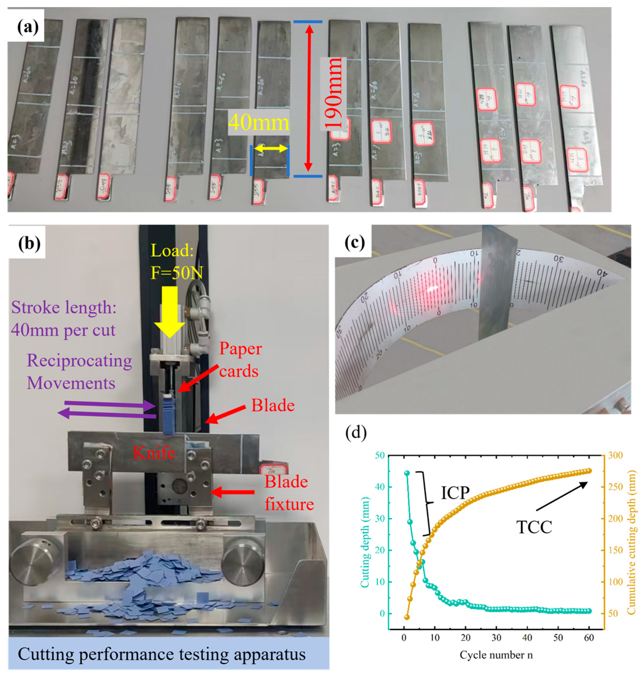
The sample preparation procedure comprised laser cutting, heat treatment, straightening, wet grinding, edge sharpening, and cleaning. After heat treatment, the blade blanks were machined to the shape of the knife shown in Figure 1a, with an overall dimension of 220 mm (L) × 40 mm (W). Edge inclusive angle is defined as the angle included between the two faces of the cutting edge, and it is a key parameter that affects the cutting performance of the knife. For CPM 3V, two edge inclusive angle groups (18° and 24°) were prepared, whereas the other five materials were fabricated with three edge inclusive angle groups (18°, 24°, and 30°). The manual sharpening error was controlled within ±1°. Given that the edge inclusive angle is a critical factor governing cutting performance, the edge inclusive angles were measured using the knife edge inclusive angle tester shown in Figure 1c. The measurement principle involves a laser beam incident perpendicular to the cutting edge, with reflections from both sides of the edge projected onto a rear reading scale; the edge inclusive angle is obtained by summing the readings of the two laser spots.
The cutting tests were conducted using a knife cutting performance testing apparatus (STX-602, Guangzhou Xitang Electromechanical Technology Co., Ltd., Guangzhou, China), and the testing procedure strictly followed the international standard ISO 8442-5:2004 [23]. As shown in Figure 1b, the sample knife was mounted horizontally in the blade fixture with the cutting edge facing upward. A strip of standardized cutting performance test card paper with a thickness of 0.31 ± 0.02 mm and a width of 10 ± 0.1 mm was placed above the edge and clamped in the card strip holder under a force of 130 ± 2.5 N. The card paper contained 5 wt.% SiO2 to enhance abrasive wear on the blade [7]. During testing, a total vertical static load of 50 ± 2 N was applied at the interface between the card and the blade by a pneumatic actuator at the start of each new test, while the blade fixture drove the blade in a reciprocating motion at a speed of 50 mm s−1 with a single cutting stroke length of 40 mm. Each test consisted of 60 cutting cycles, where one cycle corresponded to one reciprocating cut, and the penetration depth in each cycle was recorded as Di. As illustrated in Figure 1d, the green points represent the penetration depth per cycle, while the yellow points indicate the cumulative penetration depth. According to ISO 8442-5:2004, the sum of the penetration depths over the first three cycles is defined as the initial cutting performance (Icp), and the sum over 60 cycles is defined as the cutting edge retention, evaluated by the total card cut (Tcc), i.e.,
I c p = Σ i = 1 3 D i
T c c = Σ i = 1 60 D i
Both Icp and Tcc are expressed in millimeters. Icp represents the initial cutting capability perceived by users at the beginning of service, whereas Tcc reflects the ability of the knife edge to resist wear during prolonged use. This is why Icp and Tcc have become the direct metrics for knife sharpness and cutting edge retention, respectively. The ISO 8442-5:2004 standard adopts and standardizes the knife sharpness and cutting edge retention testing method invented and commercialized by CATRA (Cutlery and Allied Trades Research Association), making it a globally applicable international standard. Therefore, within the knife industry, the testing of knife sharpness and cutting edge retention is also referred to as CATRA testing.
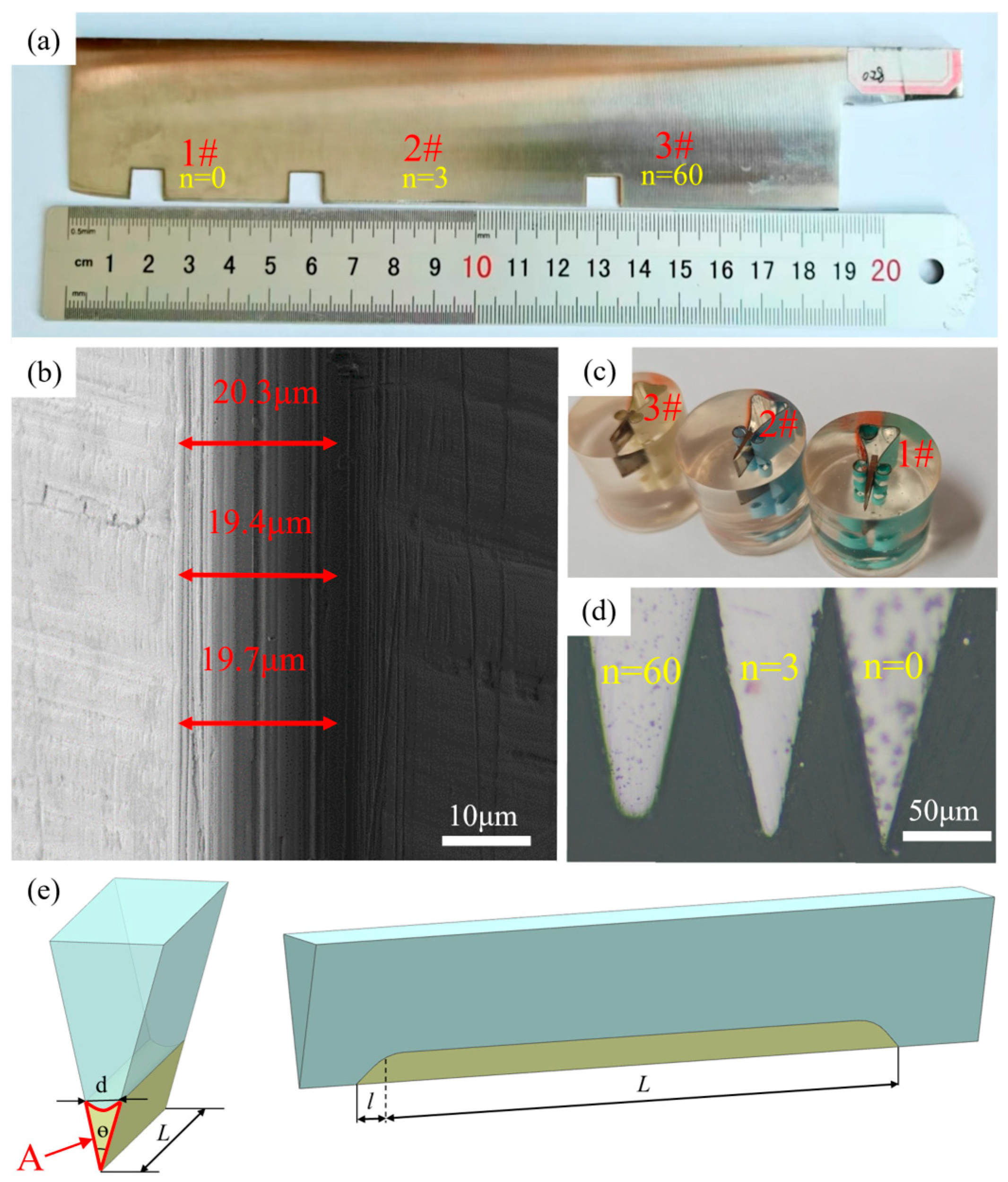
To dynamically analyze the evolution of edge wear and its relationship with cutting performance, the cutting tests were interrupted at selected cycle numbers within the 60-cycle procedure. As illustrated in Figure 2a, each specimen knife was divided into three segments: the first segment corresponded to the original edge without cutting; the second 40 mm segment represented the edge condition after 3 cutting cycles; and the third 40 mm segment represented the edge condition after 60 cutting cycles. Additional knives with identical material, heat treatment, and edge angle were then tested separately and interrupted after 1, 8, 12, 16, 20, and 35 cycles. This approach enabled preservation of the edge condition at different cutting stages, allowing characterization of the dynamic evolution of edge width and wear volume. This approach helps to minimize experimental uncertainty arising from slight variations in knife edge geometry. The specific cycle numbers selected for each experimental group are listed in Table 3.

2.3. Evaluation of Morphology and Wear Volume at Knife Edges

As shown in Figure 2c, the tested regions of the knife samples were sectioned by wire electrical discharge machining into 8 mm × 8 mm measuring samples and subsequently mounted in epoxy resin. As illustrated in Figure 2a, position 1# corresponds to the original edge prior to cutting, position 2# corresponds to the edge after 3 cutting cycles, and position 3# corresponds to the edge after 60 cutting cycles. After mounting, the specimens were sequentially ground using SiC abrasive papers from 240 to 1500 grit and then polished, with cooling water continuously used during the grinding process. The resulting edge tip morphologies observed under an optical microscope are shown in Figure 2d. The metallographic images of specimens 2# and 3# were compared with that of specimen 1# using ImageJ software (Version 1.54p 17 February 2025 (https://wsr.imagej.net/upgrade/index.html, upgrade)) to determine the material loss area A, as illustrated in Figure 2e. The wear volume of the knife edge was then calculated by multiplying the wear area A by the cutting stroke length 40 mm. As shown in Figure 2b, the frontal morphology of the knife-edge tip was examined using a Zeiss Ultra Plus scanning electron microscope (SEM) (Oberkochen, Germany). The edge tip width d was determined by importing the SEM images into ImageJ software, where each measurement was performed three times and the average value was taken as the final result.

2.4. Microstructure Analysis and Hardness Measurement

After etching in a solution composed of 5 g FeCl3, 10 mL HCl, and 85 mL H2O, the specimens were examined using a Zeiss Ultra Plus scanning electron microscope (Oberkochen, Germany) to obtain microstructural images of the knife materials. The images were then analyzed with ImageJ to determine the carbide size distribution, average carbide diameter, and carbide volume fraction. Subsequently, the microhardness of the six heat-treated steels was measured using a computer-controlled micro-Vickers hardness tester (Digi Vicker 1000A, Mager, Karachi, Pakistan). Because the indentation formed during microhardness testing occurs primarily within the metallic matrix, with carbides contributing minimally to plastic deformation at this scale, the measured microhardness values can reasonably be taken as indicative of the matrix hardness [24,25].

3. Results and Discussion

3.1. Edge Geometry

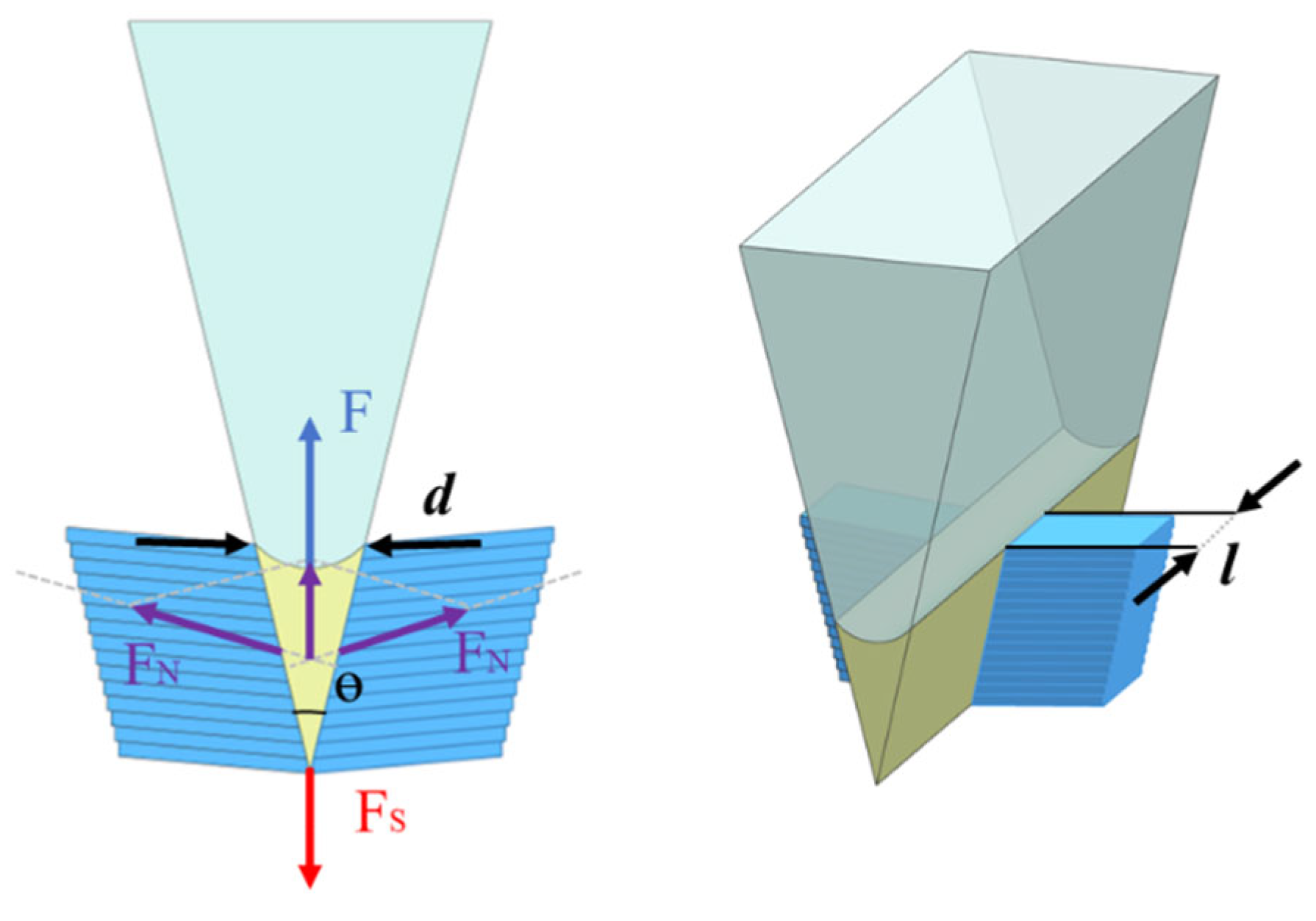
To elucidate the cutting mechanism of the test paper card and the intrinsic origin of knife cutting performance, the force state of the knife during the cutting process was analyzed. As schematically illustrated in Figure 3, when the cutting edge contacts the paper card and initiates cutting, the edge penetrates the paper while simultaneously inducing upward bending deformation. Under this contact condition, the effective force acting in the downward cutting direction can be expressed as [7]:
F S = F 2 F N sin θ 2
where FS denotes the effective force acting on the cutting contact surface, F is the normal force exerted by the paper card on the cutting edge, and FN represents the supporting forces provided by the paper card on both sides of the edge. θ represents the edge inclusive angle. Accordingly, the normal stress P acting on the cutting contact surface can be written as:
P = F S S
The contact area S is jointly determined by the edge tip width d and the width of the paper card l. Substituting these parameters into Equation (2) yields:
P = F 2 F N sin θ 2 d l
When the normal stress P on the contact surface exceeds the shear strength of the card being cut, shear failure occurs, thereby enabling the cutting process to proceed.
According to Equation (5), during the cutting performance test, the normal load F is equal to the downward force applied by the pneumatic actuator (50 N). Under this loading condition, a smaller edge inclusive angle θ and a narrower edge tip width d increase the normal stress P on the cutting contact surface, thereby facilitating shear fracture [16,26]. Consequently, the knife exhibits higher cutting performance during cutting, corresponding to a greater cutting depth of the paper card.
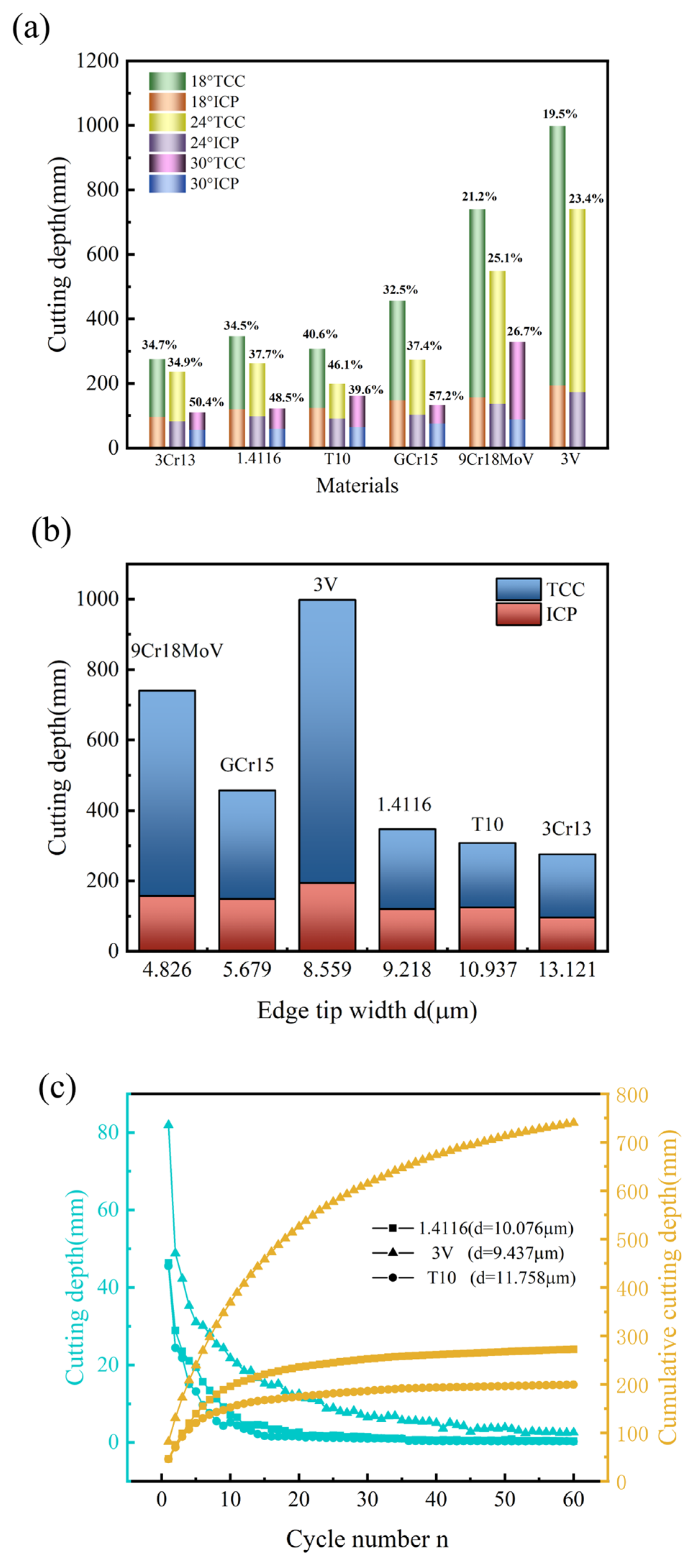
However, a smaller edge tip width does not necessarily guarantee higher cutting performance and durability. Figure 4a presents the measured ICP and TCC for all the experimental groups, while Figure 4b shows the relationship between ICP/TCC and edge width at an edge inclusive angle of 18° during the early cutting cycles (n = 3). The results indicate that both ICP and TCC generally increase with decreasing edge inclusive angle, which is consistent with the above mechanical analysis. Notably, although knife made of CPM 3V exhibits a larger edge tip width than knife made of 9Cr18MoV and GCr15, its ICP and TCC values are significantly higher than those of the latter two knives. Figure 4c further compares the cutting depth and cumulative cutting depth of the three knifes with comparable edge widths and the edge inclusive angle of 18° after three cycles, revealing pronounced differences in cutting performance, the cutting ability of CPM 3V knife is significantly better than that of T10 and 1.4116 knifes. These results demonstrate that, during CATRA testing, knife sharpness and cutting edge retention are not governed solely by edge geometric factors such as edge inclusive angle and edge tip width. The other characteristics, such as the microstructure of the material also play a critical role in determining ICP and TCC.

3.2. Microstructures and Hardness

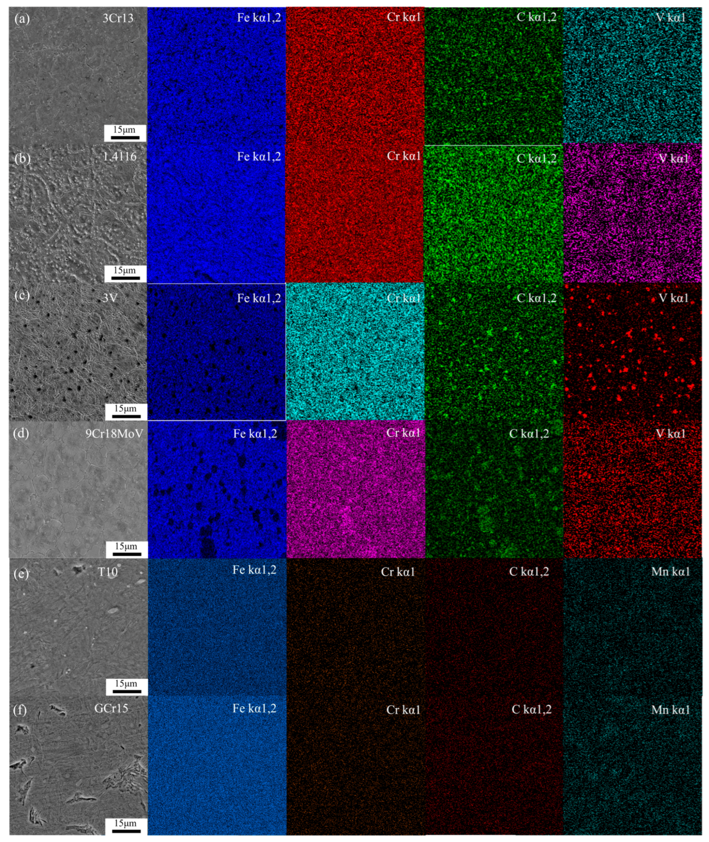
The microstructures of the knife samples were systematically analyzed. Figure 5 presents the SEM micrographs of the six samples obtained using a Zeiss Ultra Plus microscope (Oberkochen, Germany). All the samples primarily consist of tempered martensite with dispersed carbides, and prior austenite grain boundaries are clearly discernible. In the 3Cr13 sample, the carbides are mainly distributed between the lath martensite within prior the austenite grains and are relatively fine. The carbide content in the 1.4116 sample is noticeably higher than that in the 3Cr13 sample, which can be attributed to its higher carbon content. Both the CPM 3V and 9Cr18MoV samples exhibit relatively fine prior austenite grains, likely associated with the pinning effect of a higher density of carbides that suppresses austenite grain growth [27,28]. The carbides in the CPM 3V sample are more uniform in size, whereas those in the 9Cr18MoV sample show a broader size distribution: coarse carbides are mainly located along prior the austenite grain boundaries, while finer carbides are distributed within the grains. For the carbon steel T10 sample, a low population of carbides with relatively small sizes can be clearly observed. In the GCr15 sample, the irregular recessed regions in the microstructure correspond to the detachment of primary carbides, while a small number of near-spherical carbides are also present within the martensitic matrix.
SEM-EDS elemental mapping further reveals that, in the microstructures of the 3Cr13, 1.4116, and 9Cr18MoV samples, the carbides are characterized by pronounced depletion of Fe accompanied by significant enrichment of C and Cr. In the CPM 3V sample, the carbides show reduced Fe content and distinct enrichment of C and V. By contrast, in the T10 and GCr15 samples, the distributions of Fe and Cr are relatively uniform throughout the matrix, with pronounced C enrichment observed only at the carbide sites.
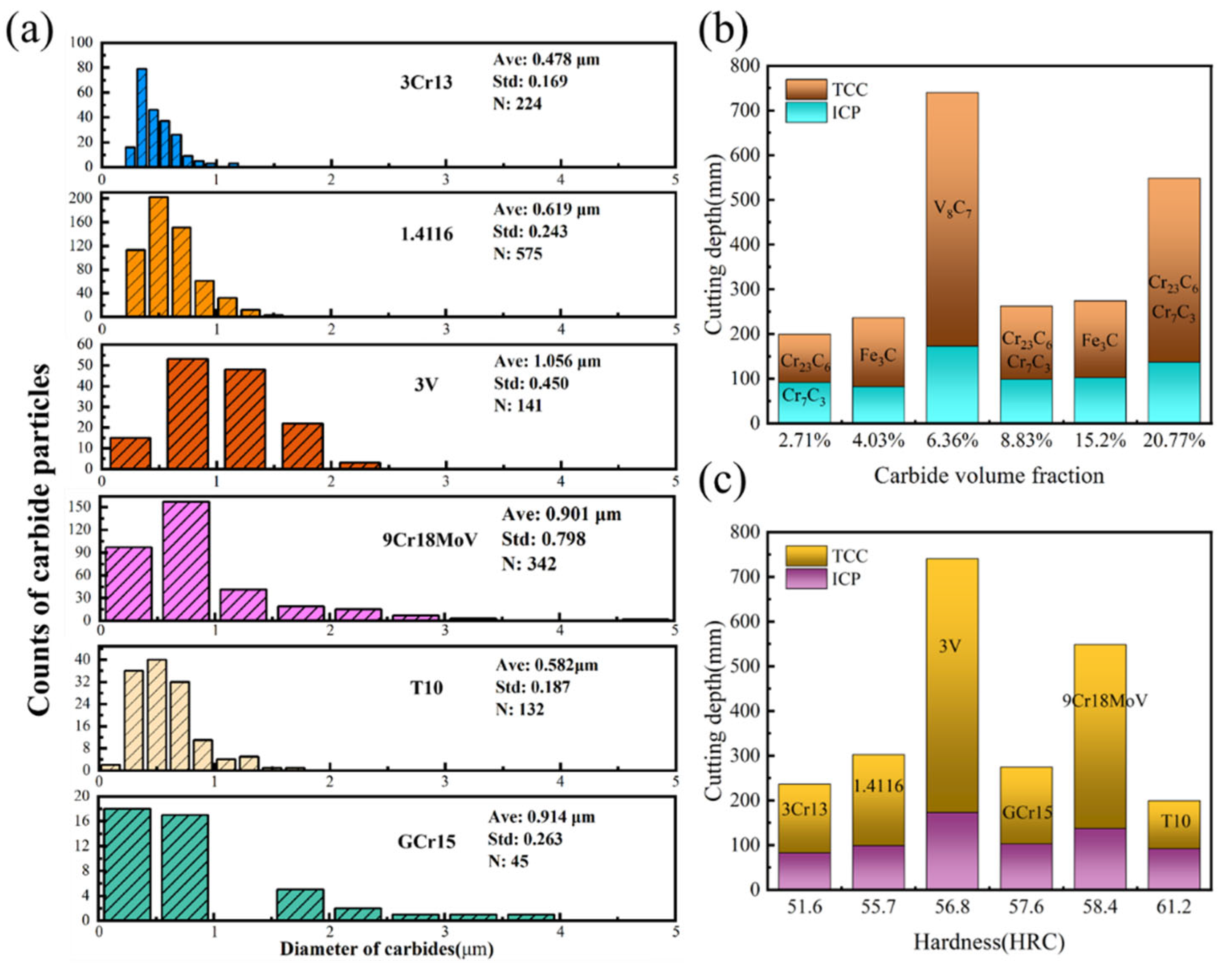
Quantitative analysis of the carbide population and size distribution is shown in Figure 6. The results indicate that the carbide sizes in the martensitic stainless steels 3Cr13 and 1.4116 samples, as well as in the carbon tool steel T10 sample, are all smaller than 2 μm and are mainly concentrated in the range of 0.2–1 μm. In contrast, the 9Cr18MoV sample exhibits a relatively broader carbide size distribution, although the majority of the carbides are still smaller than 3 μm. The carbides in the GCr15 and CPM 3V samples are comparatively larger, with a considerable fraction distributed above 1 μm. In terms of carbide number density, the 1.4116 sample contains the highest amount of carbides, whereas GCr15 shows the lowest carbide population. The average carbide diameters, volume fractions and the dominant carbide types for each sample are summarized in Table 4.
Figure 6b illustrates the dependence of the ICP and TCC on the carbide volume fractions at the edge inclusive angle of 24°. The results show that TCC generally increases with increasing carbide volume fraction, indicating that a higher carbide content enhances wear resistance during cutting and thereby increases the cutting edge retention.
As shown in Figure 6c, the relationships between the ICP, TCC and the hardness are not simply linear. For example, the T10 sample exhibits a high hardness of 61.2 HRC, yet both its ICP and TCC are markedly lower than those of the 9Cr18MoV and CPM 3V samples, which possess relatively lower hardness. In contrast, a comparison of the 3Cr13, 1.4116, and 9Cr18MoV samples, which contain similar carbide types, reveals that both the ICP and TCC increase with increasing hardness. Increased hardness allows the matrix to more effectively stabilize and support the carbides during cutting, which in turn extends their functional duration and reduces the likelihood of the carbides detachment [24,25].

3.3. Dynamic Cutting Analysis

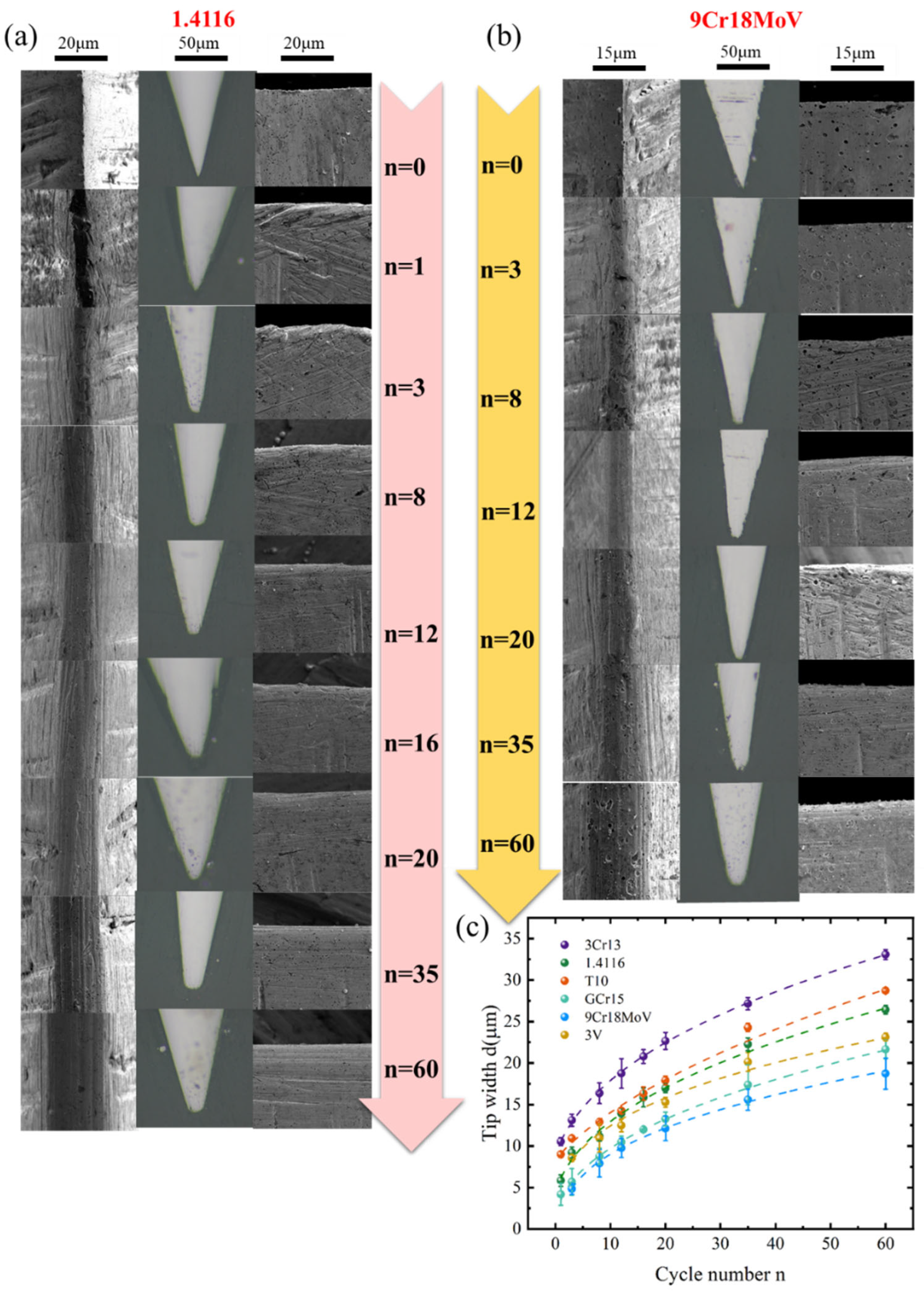
To clarify how microstructural features govern the evolution of knife cutting performance and the intrinsic causes of the differences in edge tip width evolution among samples, the entire cutting process was analyzed dynamically. Figure 7a,b present the dynamic evolution of the edge tip morphology of the 1.4116 and 9Cr18MoV samples over 60 cutting cycles, while Figure 7c shows the evolution of edge width as a function of cycle number for all six materials.
Based on geometric considerations, a definite relationship exists between the wear volume at the cutting edge and the edge tip width, which can be expressed as:
V = L d 2 4 tan ( θ / 2 )
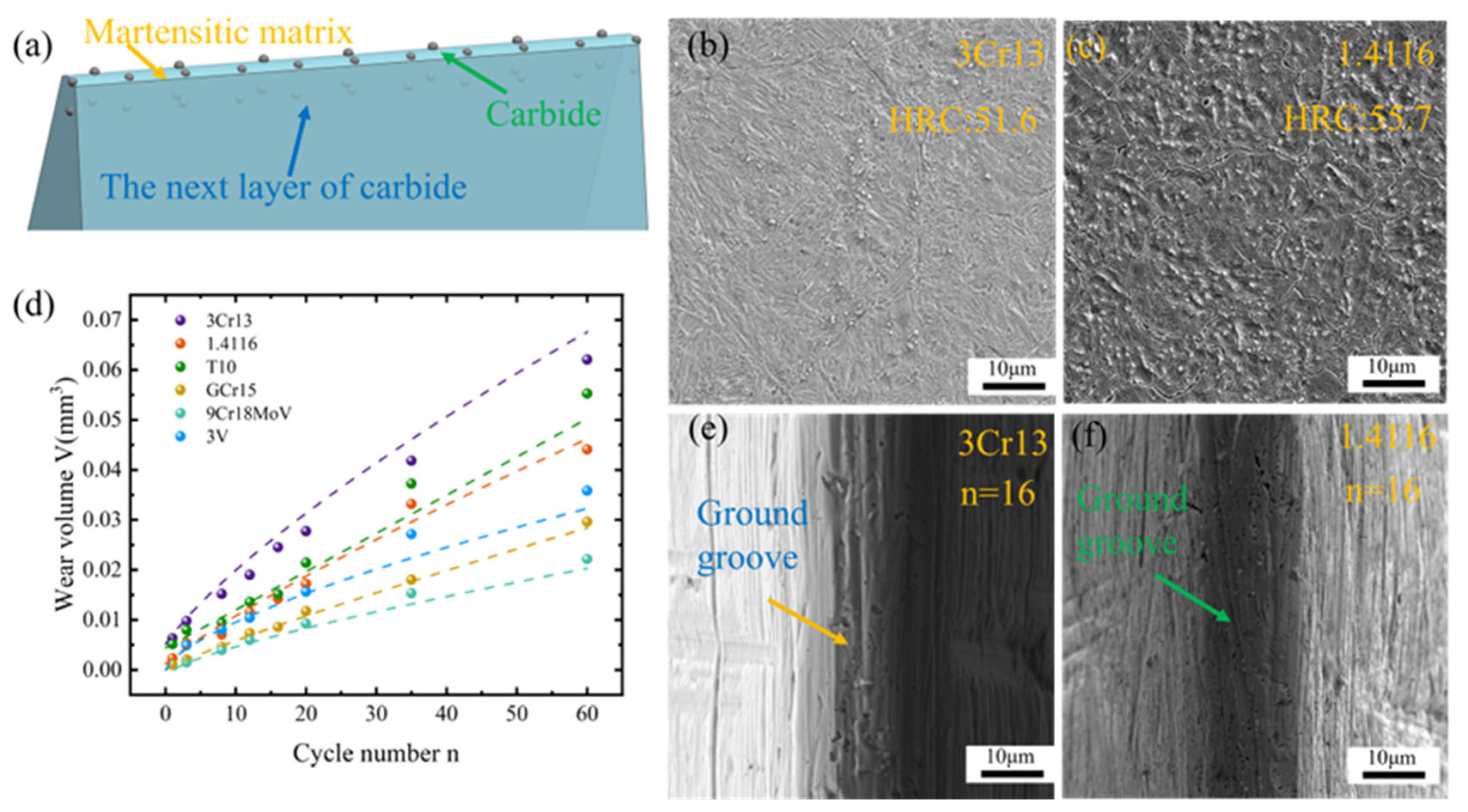
where V is the wear volume of the cutting edge and L is the cutting stroke length. Figure 8d illustrates the evolution of the cutting-edge wear volume as a function of cutting cycles for the different samples at edge inclusive angle of 18°. The results indicate that the wear resistance of the investigated samples decreases in the following order: 9Cr18MoV, GCr15, CPM 3V, 1.4116, T10, and 3Cr13. This ranking is in good agreement with the corresponding evolution trends of edge tip width, confirming the strong correlation between wear volume and edge geometry degradation during cutting.
Due to the relatively low alloying element content in T10, although it contains a high carbon level, it fails to form a sufficient amount of carbides, which are the key microstructural constituents governing the wear resistance of steel. Carbides are widely recognized as a critical microstructural factor governing the wear resistance of steels [10,30,31,32]. In the T10, most of the carbon remains in solid solution within the martensitic matrix, and the hardness of the martensites is primarily determined by its carbon content [33,34]. Consequently, the T10 sample exhibits relatively high hardness but poor wear resistance. In contrast, GCr15 contains a certain amount of Cr. Although its carbon content is comparable to that of T10 and its hardness is slightly lower, its wear resistance is significantly improved, second only to 9Cr18MoV. This behavior can be attributed to the precipitation of a large number of relatively coarse carbides along prior austenite grain boundaries in the GCr15, which consume part of the carbon and thereby reduce the carbon content in the martensitic matrix, leading to a moderate decrease in hardness. Meanwhile, the higher carbide fraction effectively suppresses abrasive wear [35,36,37], resulting in superior wear resistance compared with the T10.
A comparison of the wear volume evolution among martensitic stainless steels with different carbon contents, namely 3Cr13, 1.4116, and 9Cr18MoV, reveals that the cutting-edge wear volume generally decreases with increasing carbon content. Combined with the microstructural observations shown in Figure 5, this trend is mainly attributed to the substantially higher carbide content and smaller prior austenite grain size in the 9Cr18MoV sample, which endow the material with improved overall mechanical properties [38,39]. Moreover, owing to its higher carbon content, even after partial carbon consumption by the carbides, a certain amount of carbon remains in solid solution within the martensitic matrix of the 9Cr18MoV sample, allowing the matrix hardness to be maintained at a relatively high level and thereby further enhancing its wear resistance.
By comparing the cutting performance evolution curves of the 3Cr13 and 1.4116 samples together with the microstructural features shown in Figure 8b,c, it can be observed that although the carbide size in the 1.4116 sample is comparable to that in the 3Cr13 sample and only slightly higher in number, the cutting performance of the 1.4116 sample is significantly superior. This indicates that, during the cutting process, the martensitic matrix plays a crucial role in maintaining cutting performance. A higher matrix hardness can provide more sustained encapsulation and mechanical support for carbides during cutting [6], thereby reducing their tendency to be worn, fractured, or detached. Meanwhile, a relatively higher carbide population can also protect the matrix by reducing the effective interfacial area directly involved in wear, which in turn lowers the wear rate of the matrix itself.
Under this synergistic effect of the matrix and the carbides, carbides located beneath the surface are less likely to be prematurely exposed and participate in the cutting process, effectively retarding the evolution of edge width. As a result, the knifes exhibit improved wear resistance and enhanced cutting edge retention. Further evidence can be obtained from the edge morphologies shown in Figure 8e,f, where deeper wear grooves are clearly observed on the cutting edge of the 3Cr13 sample with lower matrix hardness, whereas only shallow scratches appear on the harder matrix of the 1.4116 sample. These observations further confirm that increasing matrix hardness enhances the stability of the carbides during cutting, thereby significantly improving cutting performance of the knifes.
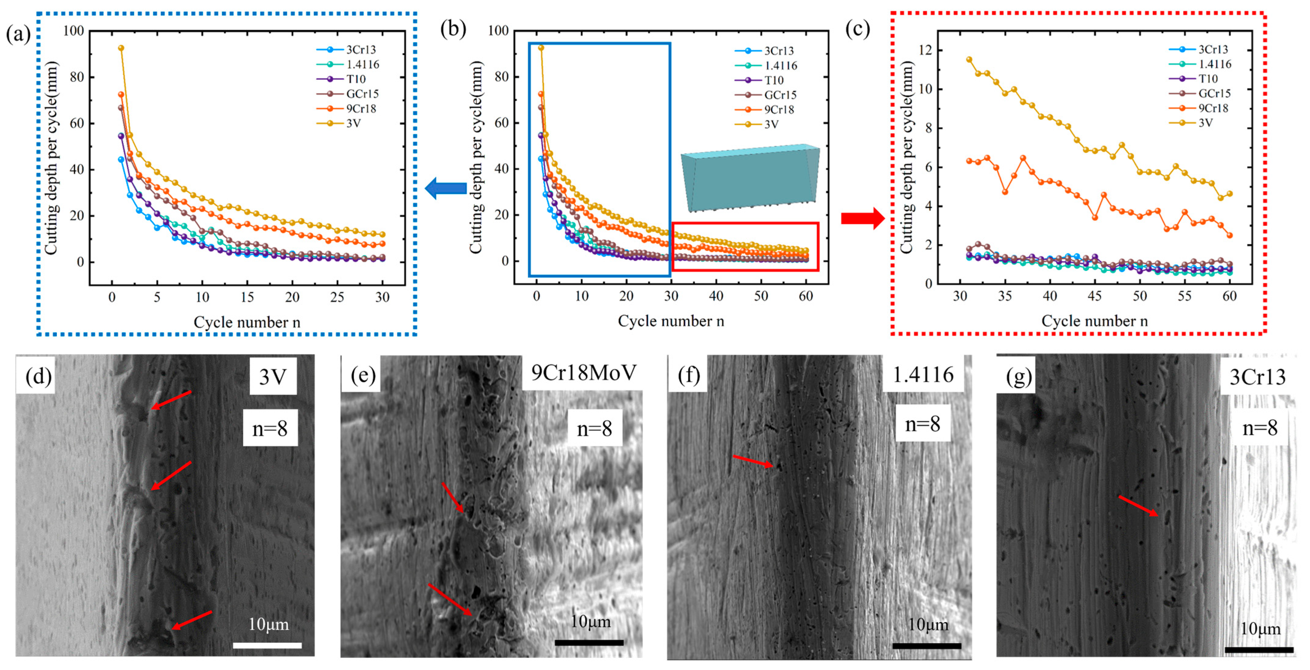
As shown in Figure 9b, the variation in the penetration depth per cycle over the 60 cutting cycles for the six samples at edge inclusive angle of 18° is presented. The CPM 3V and 9Cr18MoV samples exhibit a much more gradual cutting degradation, which is consistent with their lower ICP/TCC ratios shown in Figure 4a. To further analyze the cutting degradation, the 60 cutting cycles were divided into the first 30 cycles and the last 30 cycles, and the corresponding cutting results are presented in Figure 9a and Figure 9c, respectively.
The results indicate that the evolution of knife cutting performance with cutting cycles does not follow a strictly monotonic decreasing trend; instead, a temporary recovery of cutting performance is observed during certain cycles. This phenomenon is mainly attributed to the progressive exposure of carbides at the cutting edge during the cutting process. As carbides emerge from the edge apex, the contact mode at the cutting edge gradually changes from an initial line contact to localized point contact, which effectively reduces the real contact area and further increases the normal stress acting on the cutting interface. Under enhanced contact stress, the tested material is more prone to shear failure, producing a cutting behavior analogous to a micro-serrated edge effect [5]. Consequently, an apparent recovery of cutting performance can be observed in specific cutting cycles. Figure 9d–g show that the CPM 3V and 9Cr18MoV samples possess larger carbides than the 1.4116 sample, while exhibiting comparable matrix hardness; nevertheless, their cutting degradation is markedly slower, indicating that larger carbides are more effective than smaller ones in enhancing the cutting action.
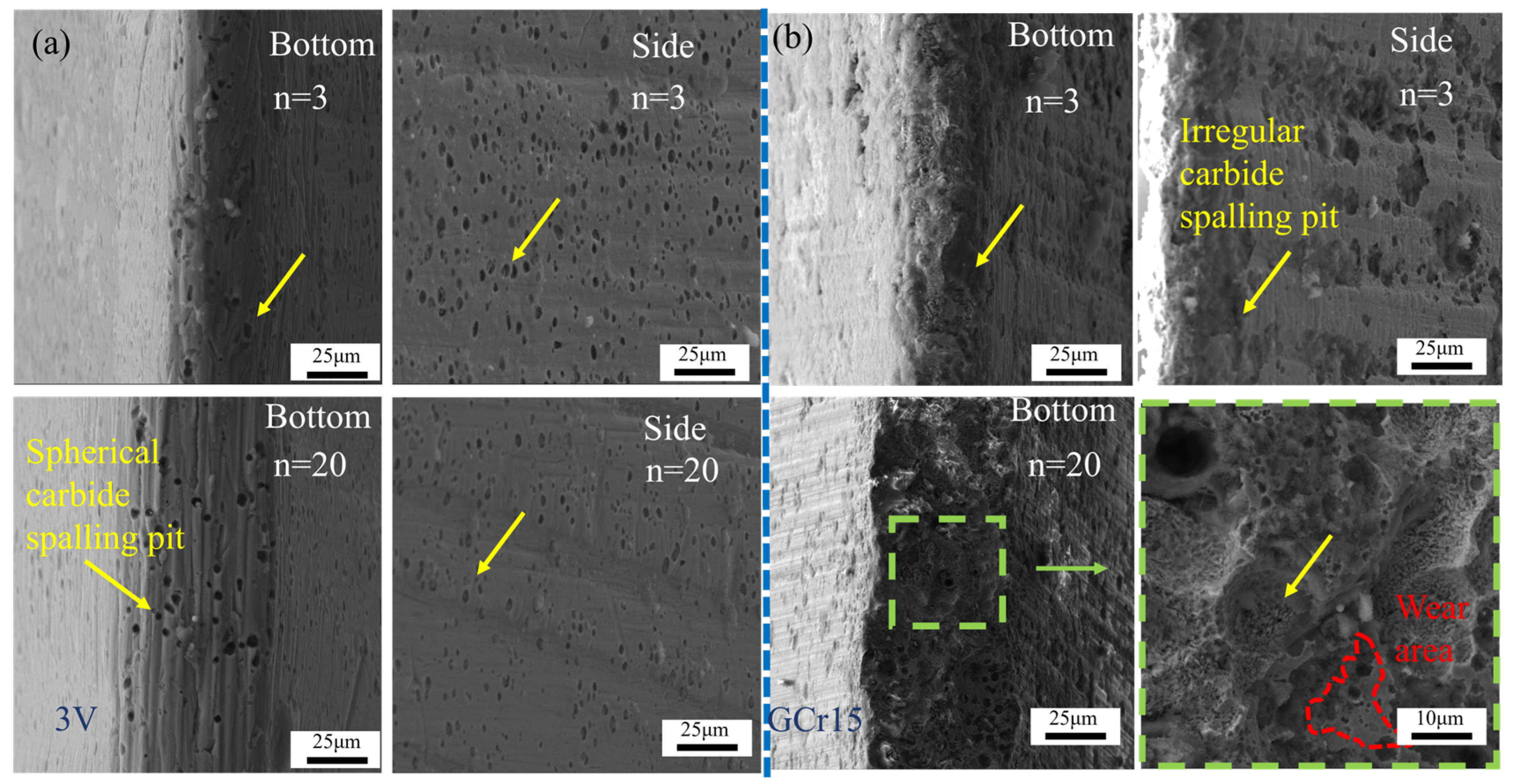
The morphology of carbides also exerts a pronounced influence on knife cutting performance. Figure 10 presents the frontal views of the cutting-edge tips of the CPM 3V and GCr15 samples after 3 and 20 cutting cycles, respectively. The yellow arrow in the picture indicates a pit formed after the carbide has fallen off. Combined with the corresponding microstructural observations, it can be seen that the carbides in the CPM 3V sample are predominantly spherical and uniformly distributed within the martensitic matrix, whereas the GCr15 sample contains a large number of coarse carbides with irregular morphologies.
After three cutting cycles, observations of both the frontal and lateral morphologies of the cutting edges indicate that, in the GCr15 sample, a considerable number of large and irregular carbides detach from the matrix or are fractured under plowing action during cutting test. This leads to a loss of edge straightness and consequently increases cutting resistance. In contrast, the cutting edge of the CPM 3V ample remains relatively continuous and straight. As the number of cutting cycles increases to 20, the cutting-edge tip of the GCr15 sample no longer exhibits a regular arc-shaped geometry; instead, extensive carbide spallation results in the formation of a markedly rough surface. Further high-magnification observations clearly reveal the matrix–carbide interfacial features left after carbide detachment, as well as the pronounced smoothing and wear of the surrounding matrix.
These results indicate that spheroidal carbides exhibit a stronger interfacial bonding with the matrix, which is more conducive to maintaining the geometric stability of the cutting edge. In contrast, carbides with larger sizes and irregular morphologies are more prone to detachment during cutting, leading to a loss of edge-line continuity and, consequently, a weakened cutting action. After carbide spallation, the cutting-edge tip rapidly becomes flattened, resulting in an increased contact area between the edge and the test paper and a corresponding reduction in the normal contact stress. This mechanism provides a clear explanation for the relatively rapid cutting performance degradation of the GCr15 sample in the later stages of cutting, despite its relatively small evolution in edge width and its comparatively high wear resistance.
Nevertheless, the universal superiority of a smaller edge inclusive angle warrants further discussion. While a reduced edge inclusive angle increases the effective cutting force at the contact interface, thereby enhancing normal stress and facilitating material shear fracture, it also accelerates material removal at the edge apex from a wear perspective [40,41,42]. According to the Archard wear model:
V = K W L H
where V is the wear volume, K is the wear coefficient, W is the normal load, L is the sliding distance, and H is the hardness of the knife.
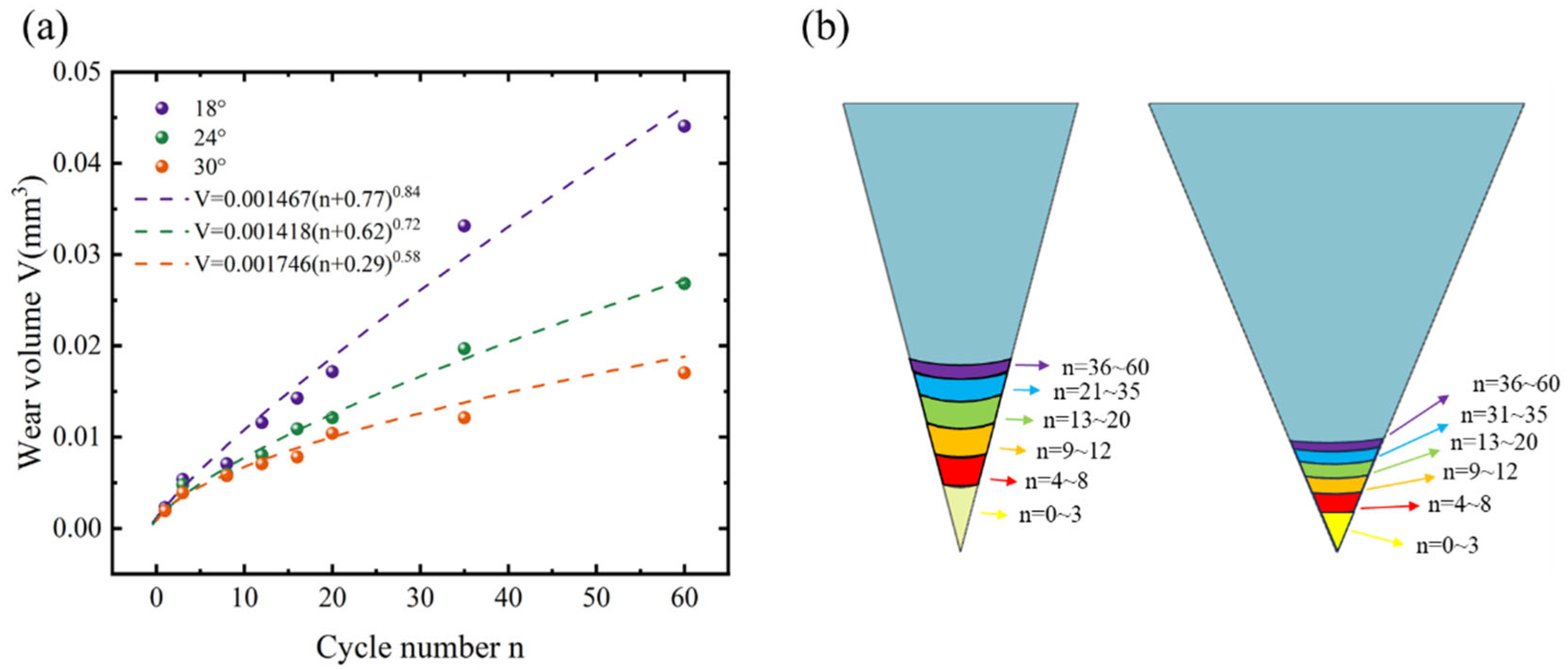
Under constant normal load and knife hardness, a smaller edge inclusive angle concentrates local loads and sliding action more intensely at the edge apex during cutting. This increases the wear volume per unit cutting stroke and accelerates the edge width growth rate, an analytical conclusion corroborated by the experimental edge width evolution for knives with different edge inclusive angles, as illustrated in Figure 11a.
Given that a smaller edge inclusive angle enhances cutting performance but accelerates wear (thus shortening service life), an integrated parameter is required to quantitatively evaluate the trade-off between sharpness and cutting edge retention. Therefore, a cutting efficiency factor K is introduced, defined as the cutting capability per unit wear volume:
K = C C D V
where K represents the cutting efficiency, CCD (mm) is the cumulative cutting depth, and V (mm3) is the corresponding wear volume of the cutting edge.
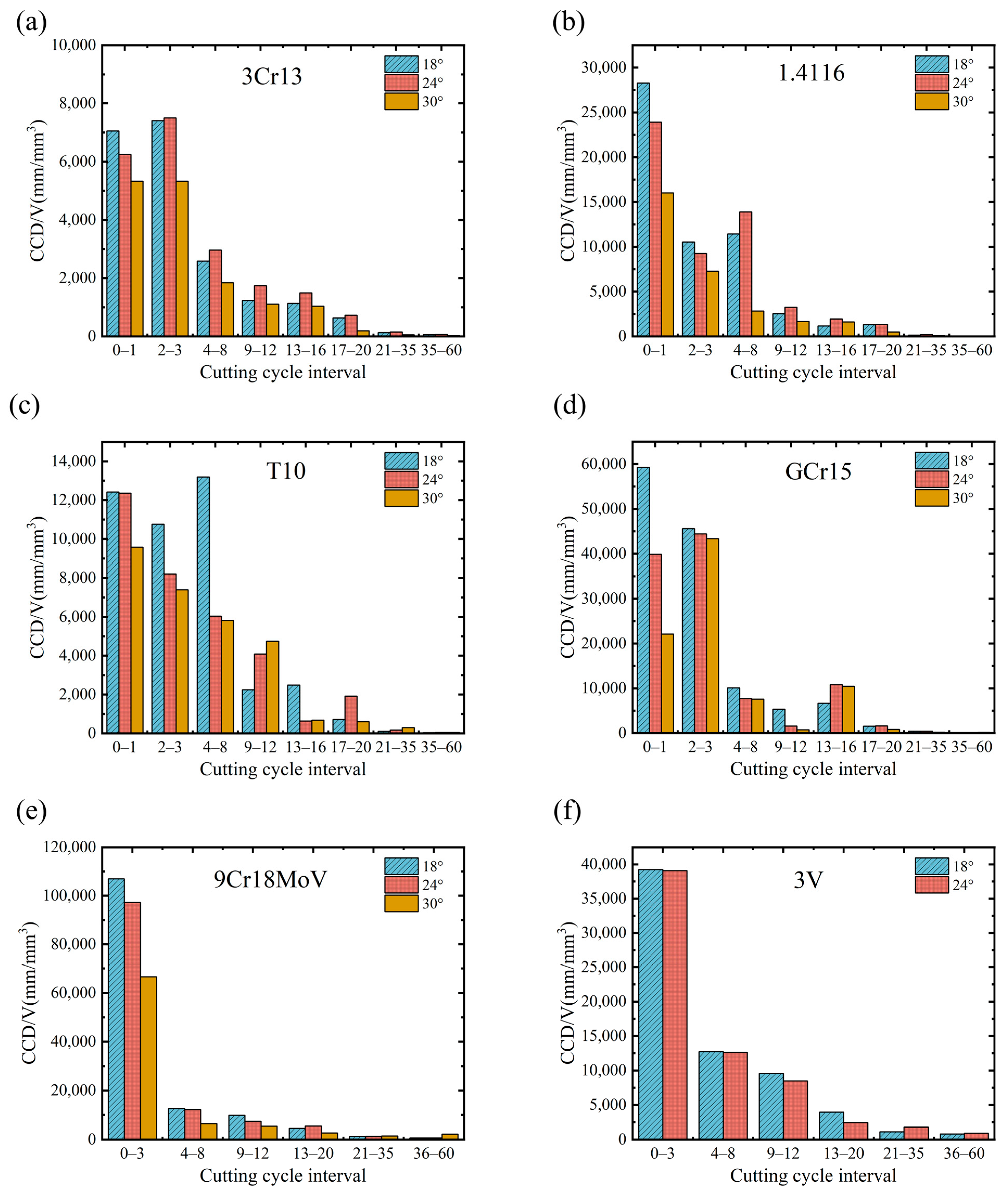
To dynamically analyze cutting efficiency and compare the differences in the samples throughout the entire testing process, the total 60 cutting cycles were divided into intervals based on preset cycle numbers. For each sample, the cumulative cutting depth per unit wear volume (CCD/V) within each interval was normalized by the cycle count, yielding the average in that interval. The results are presented in Figure 12. Overall, the cutting efficiency of all the samples exhibits pronounced stage-wise decay with increasing cycles; however, the decay magnitude and dominant stages vary significantly among the samples and the edge inclusive angles.
Initial Cutting Stage (0–1 cycles):
All the samples exhibited relatively high cutting efficiency initially. Specifically, the 3Cr13, 1.4116, T10, and GCr15 samples achieved the highest K values at the smallest edge inclusive angle (18°) during the first 0–1 cycle. This is attributed to the cutting edge maintaining a continuous, straight geometry at this stage, where performance is dominated by interfacial normal stress and matrix hardness, with minimal carbide involvement [5]. Consequently, the higher contact stress associated with a smaller edge inclusive angle results in greater cutting efficiency.
Transition Stage (2–8 cycles):
As cutting progressed to 2–8 cycles, carbides gradually became exposed at the cutting edge and began participating in the process. Under these conditions, the samples with higher carbide contents exhibited cutting efficiencies at the larger edge inclusive angle (24°) that approached or even exceeded those at 18°. This shift occurs because carbide involvement introduces a point-contact cutting mode, which reduces the real contact area between the edge and test paper, thereby increasing local contact stress and enhancing the cutting efficiency of samples with larger edge inclusive angles [5,6]. In contrast, for the T10 sample, with its relatively small carbide size and low volume fraction, edge width evolution and wear behavior remained governed by matrix hardness. Thus, the higher contact stress from a smaller edge inclusive angle continued to dominate, allowing the T10 sample to maintain significantly higher cutting efficiency at smaller angles.
Intermediate Stage (9–20 cycles):
A pronounced decline in cutting efficiency was observed for all the samples in this stage, but material-specific differences emerged and widened. For samples with uniform carbide distribution and near-spherical carbide morphology, such as the 9Cr18MoV and CPM 3V samples, the decrease in CCD/V was relatively moderate, and high cutting efficiency was maintained over a broad cycle range. This indicates that accumulated wear volume had reached a level where increased edge width exposed more carbides, creating a micro-serration effect that partially sustained cutting capability [10]. At this stage, both the 3Cr13 and 1.4116 samples exhibited significantly higher cutting efficiency at 24° than at other angles. A comparison of the 9Cr18MoV and CPM 3V samples with the 3Cr13 and 1.4116 samples between the intermediate (9–20 cycles) and early (4–8 cycles) stages reveals that the latter samples experienced a more rapid cutting efficiency decline, whereas the former samples showed gradual changes. This behavior is primarily attributed to the presence of larger, spherical carbides in the 9Cr18MoV and CPM 3V samples, which provide a pronounced beneficial effect on cutting once edge width increases, whereas finer carbides mainly enhance wear resistance with limited direct cutting contribution. Additionally, the GCr15 sample exhibited a transient efficiency recovery, associated with premature detachment of the large, irregular carbides during early cutting, which increased real contact area and reduced edge tip stress, resulting in lower wear volume per unit cutting depth.
Late Cutting Stage (21–60 cycles):
The CCD/V values of most samples converged to low levels with reduced fluctuations, indicating that cutting efficiency had entered a plateau. At this stage, edge tip width and wear volume evolution approached a quasi-steady state, and the cutting mechanism shifted from shear-dominated cutting to frictional plowing [7]. Consequently, all the effective cutting depths per unit wear volume decreased markedly. Under these conditions, the samples with larger edge inclusive angles generally exhibited higher cutting efficiency than those with smaller angles, suggesting that once a certain wear degree is reached, a larger edge inclusive angle reduces effective cutting force and contact stress, thereby slowing further wear and increasing the cutting depth per unit wear volume.
In summary, as the cutting edge blunts and the edge tip width increases, carbide characteristics progressively dominate the cutting efficiency. Larger carbide size, uniform distribution, and spherical morphology promote stable carbide–matrix synergy, resulting in slower cutting degradation and improved cutting efficiency. Combined with the ICP/TCC values in Figure 4a, it is evident that early-stage cutting performance is controlled by edge inclusive angle and matrix hardness, whereas later-stage performance is increasingly governed by the carbide size, morphology, and interfacial bonding strength.
Critically, a smaller edge inclusive angle is not universally optimal, but an appropriate design window exists. Excessively small angles cause severe stress concentration and accelerated edge tip wear, leading to rapid blunting, reduced knife life, and lower cutting efficiency per unit wear volume. Under the investigated conditions, the samples made of the low- and medium-carbon martensitic stainless steels like 3Cr13 and 1.4116 achieve optimal ICP-TCC balance at the edge inclusive angle of 24°, whereas the samples made of the high-carbon martensitic stainless steels and powder metallurgy tool steels like 9Cr18MoV and CPM 3V perform better at angles close to 18°.
For carbon tool steel T10, the service life of the sample is generally short due to the limited carbide volume fraction, and its cutting performance relies mainly on high matrix hardness. Such knives require frequent re-sharpening in practice. Although the GCr15 sample contains large carbides, their irregular morphology predisposes them to detachment in later cutting stages, compromising edge-line continuity and restricting long-term performance.

3.4. Predictive Modeling

Predictive models were established using experimental data from this study to aid knife manufacturers in design and production. These models enable the prediction of sharpness and cutting edge retention of knifes based on factory-accessible parameters, thereby reducing prototyping and validation costs.
The Icp and Tcc were taken as the dependent variables, while the edge inclusive angle (θ), material hardness (H), average carbide diameter (D), and edge tip width (d) were selected as independent variables. All experimental datasets were included in the regression analysis to determine the quantitative relationships between these parameters.
The regression coefficients were determined using the least-squares method. The goodness of fit of the models was evaluated using the coefficient of determination (R2). The resulting regression equations are expressed as follows:
I c p = 141.43 5.238 θ + 0.022 H + 0.127 D 0.129 d
T c c = 722.58 28.38 θ + 4.9 H + 1.16 D 20.66 d
The regression results show that the model for Icp has a coefficient of determination R2 = 0.88, while the model for Tcc shows R2 = 0.81, indicating good agreement between the predicted and experimental values. Rearranging Equation (6) and substituting the cutting stroke length L yields the relationship between edge tip width and wear volume:
d = 3162.28 V   tan θ / 2 1 / 2
Substituting Equation (11) into Equations (9) and (10) provides the relationships between Icp, cutting edge retention, and wear volume:
I c p = 141.43 5.238 θ + 0.022 H + 0.127 D 407.93 V   tan θ / 2 1 / 2
T c c = 722.58 28.38 θ + 4.9 H + 1.16 D 65332.7 V   tan θ / 2 1 / 2
where θ (°) is the edge inclusive angle, H (HRC) is the material hardness, D (nm) is the average carbide diameter, d (μm) is the edge tip width, and V (mm3) is the edge wear volume.
Based on the absolute values of the regression coefficients, the relative significance of factors affecting Icp is ranked as: edge inclusive angle θ > edge width d > average carbide diameter D > material hardness H. Overall, achieving knives with high ICP and excellent cutting edge retention requires controlling the edge inclusive angle within a material-specific optimal range, maximizing material hardness, and optimizing carbide morphology to obtain larger, highly spheroidized carbides. These strategies collectively enhance cutting performance retention and service performance.

4. Conclusions

This study systematically investigated the effects of edge geometry and microstructural characteristics on the cutting performance evolution, wear behavior, and cutting efficiency of the knifes during CATRA testing. By combining controlled cutting experiments with microstructural characterization and quantitative wear analysis, the dominant factors governing sharpness and cutting edge retention at different cutting stages were identified. Furthermore, quantitative predictive models were established to correlate ICP and TCC with key geometric and material parameters. Based on these results, the following conclusions were drawn:
  • Dynamic analysis revealed that the evolution of cutting performance in the CATRA test can be divided into four distinct stages. During the 0–1 cycles, edge inclusive angle and material hardness determine the ICP, with smaller edge inclusive angles and higher hardness resulting in superior cutting capability. In the 2–8 cycle stage, carbides begin to participate in the cutting process and generate a micro-serration effect, thereby enhancing cutting efficiency. During the 9–20 cycles, large and uniformly distributed spherical carbides effectively retard sharpness degradation and continuously contribute to cutting action. In the final stage (21–60 cycles), the cutting mechanism gradually transitions to friction-dominated plowing, and the knife essentially loses its effective cutting capability.
  • Effect of edge geometry on cutting performance: A smaller edge inclusive angle and narrower edge tip width lead to higher normal contact stress at the edge, thereby enhancing material removal capability and increasing sharpness. However, excessively small edge inclusive angles accelerate edge wear and consequently reduce knife service life.
  • Effect of microstructure on cutting performance: Carbide morphology plays a critical role in cutting performance retention. Spherical carbides exhibit stronger interfacial bonding with the matrix, contributing to greater edge stability. In contrast, irregularly shaped carbides are more prone to fracture or detachment during cutting, resulting in edge line discontinuity and accelerated cutting performance degradation. Large carbides generate a more pronounced micro-serration effect, significantly improving cutting efficiency; however, their detachment in the edge region can cause a sharp decline in performance. A high-hardness matrix provides effective support to carbides, reducing their detachment during cutting, while a higher carbide population protects the matrix and retards matrix wear.
  • Combined influence of edge geometry and microstructure: The optimal edge inclusive angle varies among materials. Under the material systems and testing conditions investigated in this study, medium–low carbon martensitic stainless steel (e.g., 3Cr13 and 1.4116) achieve a favorable balance between sharpness and durability at an edge inclusive angle of approximately 24°, whereas high-carbon martensitic stainless steels (e.g., 9Cr18MoV) and powder metallurgy tool steels (e.g., CPM 3V) exhibit superior cutting efficiency at edge inclusive angles close to 18°.
  • Predictive models: Multivariate linear regression models were successfully established, relating ICP and TCC to key parameters such as including edge inclusive angle, material hardness, average carbide diameter, and edge width. Based on the regression coefficients, the relative significance of factors affecting ICP and TCC is ranked in descending order: edge inclusive angle, edge width, average carbide diameter, and material hardness.

Author Contributions

Conceptualization, Q.Z. and W.L.; Methodology, Q.Z. and D.W.; Software, Y.W. and Y.L.; Validation, S.X., R.H. and Y.L.; Formal Analysis, S.X., R.H. and Y.W.; Investigation, S.X. and Y.L.; Resources, Q.Z.; Data Curation, S.X. and R.H.; Writing—Original Draft Preparation, S.X.; Writing—Review and Editing, Q.Z. and D.W.; Visualization, S.X. and Y.W.; Supervision, Q.Z., D.W. and W.L.; Project Administration, Q.Z. and W.L.; Funding Acquisition, Q.Z. All authors have read and agreed to the published version of the manuscript.

Funding

This work was supported by the Guangdong S&T Programmer Supporting the ‘100 Counties, 1000 Towns, 10,000 Villages’ Project in Guangdong (No. BQW2024004) and sponsored by the Talent revitalization project for key industries of alloy materials of Yangjiang City (No. RCZX2025007).

Institutional Review Board Statement

Not applicable.

Informed Consent Statement

Not applicable.

Data Availability Statement

The data presented in this study are available on request from the corresponding author. The data are not publicly available due to privacy.

Conflicts of Interest

Authors Qinyi Zhang and Wei Liu were employed by the company Yangjiang Tuobituo Industrial Technology Research Institute Co., Ltd. The remaining authors declare that the research was conducted in the absence of any commercial or financial relationships that could be construed as a potential conflict of interest.

References

  1. Savescu, A.; Cuny-Guerrier, A.; Wild, P.; Reno, G.; Aublet-Cuvelier, A.; Claudon, L. Objective Assessment of Knife Sharpness over a Working Day Cutting Meat. Appl. Ergon. 2018, 68, 109–116. [Google Scholar] [CrossRef]
  2. Ageev, O.V.; Dowgiałło, A.; Sterczyńska, M.; Piepiórka-Stepuk, J.; Samojlova, N.V.; Jakubowski, M. Increasing the Efficiency of Food Material Cutting during Inclined and Shear Movements of Knife. Materials 2021, 15, 289. [Google Scholar] [CrossRef]
  3. Mihelič, M.; Vusić, D.; Ursić, B.; Zadro, A.; Spinelli, R. The Effect of Knife Wear and Sharpening Mode on Chipper Productivity and Delays. Forests 2024, 15, 1101. [Google Scholar] [CrossRef]
  4. Kumar, P.; Abubakar, A.A.; Imlan, J.C.; Ahmed, M.A.; Goh, Y.-M.; Kaka, U.; Idrus, Z.; Sazili, A.Q. Importance of Knife Sharpness during Slaughter: Shariah and Kosher Perspective and Scientific Validation. Animals 2023, 13, 1751. [Google Scholar] [CrossRef] [PubMed]
  5. Zhang, Q.; Liu, F.; Wu, D.; Qu, S.; Liu, W.; Chen, Z. A Comprehensive Understanding of Knife Cutting: Effects of Hardness, Blade Angle and the Micro-Geometry of Blade Edge on the Cutting Performance. Materials 2023, 16, 5375. [Google Scholar] [CrossRef]
  6. Wu, D.; Zhang, Q.; Liu, W. Effect of Alloying Elements on the Sharpness Retention of Knife Blades Made of High Carbon Martensitic Stainless Steels. Metals 2022, 12, 472. [Google Scholar] [CrossRef]
  7. Wu, D.; Qu, S.; Zhang, Q.; Zhou, H. A Quantitative Model That Correlates Sharpness Retention and Abrasive Wear of Knife Blades. Wear 2023, 518–519, 204634. [Google Scholar] [CrossRef]
  8. Rodríguez Herrejon, V.; Ruiz, A.; Bedolla-Jacuinde, A.; Nadimpalli, V.K. Comparative Analysis of Wear Properties of 440C Tool Steel Fabricated by Spray Forming and Conventional Casting. J. Mater. Eng. Perform. 2025, 34, 27070–27087. [Google Scholar] [CrossRef]
  9. Guo, F.; Peng, Z.; Lu, G.; Liu, W.; Li, G.; Zhang, P.; Shang, C. Enhanced Cutting Performance of 50Cr15MoV Martensitic Stainless Steel Through Controlled Residual Austenite Stability. Metals 2025, 15, 95. [Google Scholar] [CrossRef]
  10. Wu, D.; Qu, S.; Zhang, Q.; Zhou, H. Enhanced Wear Resistance of Blades Made of Martensitic Steels: A Study of Diverse A′-Matrix/Carbide Microstructures. Mater. Charact. 2023, 201, 112939. [Google Scholar] [CrossRef]
  11. Corrêa, J.G.; Schroeter, R.B.; Machado, Á.R. Tool Life and Wear Mechanism Analysis of Carbide Tools Used in the Machining of Martensitic and Supermartensitic Stainless Steels. Tribol. Int. 2017, 105, 102–117. [Google Scholar] [CrossRef]
  12. Abbasi, E.; Luo, Q.; Owens, D. Case Study: Wear Mechanisms of NiCrVMo-Steel and CrB-Steel Scrap Shear Blades. Wear 2018, 398–399, 29–40. [Google Scholar] [CrossRef]
  13. Hawryluk, M.; Lachowicz, M.; Łukaszek-Sołek, A.; Lisiecki, Ł.; Ficak, G.; Cygan, P. Structural Features of Fatigue Crack Propagation of a Forging Die Made of Chromium–Molybdenum–Vanadium Tool Steel on Its Durability. Materials 2023, 16, 4223. [Google Scholar] [CrossRef] [PubMed]
  14. Xue, K.; Chen, P.; Liu, W.; Zou, B.; Li, L.; Chen, W.; Wang, X.; Xu, Z. Geometric Structures for Sialon Ceramic Solid End Mills and Its Performance in High-Speed Milling of Nickel-Based Superalloys. Coatings 2023, 13, 1483. [Google Scholar] [CrossRef]
  15. Singh, V.; Das, M.; Kumar Das, S. Effects of Knife Edge Angle and Speed on Peak Force and Specific Energy When Cutting Vegetables of Diverse Texture. Int. J. Food. Stud. 2016, 5, 22–38. [Google Scholar] [CrossRef]
  16. Peng, Z.; Guo, F.; Liu, W.; Zhang, P.; Mai, Y.; Shang, C. The Coupled Influence of Material and Geometric Parameters on Cutting-Edge Micro-Morphology and Wear Property Degradation. Metals 2025, 15, 264. [Google Scholar] [CrossRef]
  17. Keturakis, G.; Lisauskas, V. Influence of the Sharpness Angle on the Initial Wear of the Wood Milling Knives. Mater. Sci. 2010, 16, 205–209. [Google Scholar]
  18. Liu, Q.; Qian, D.; Wei, W. Microstructural Evolution of GCr15 Steel during Austenitizing and Quenching Considering C and Cr Content. J. Cent. South Univ. 2016, 23, 2492–2499. [Google Scholar] [CrossRef]
  19. Krbata, M.; Kohutiar, M.; Escherova, J.; Klučiar, P.; Studeny, Z.; Trembach, B.; Beronská, N.; Breznická, A.; Timárová, Ľ. Continuous Cooling Transformation of Tool Steels X153CrMoV12 and 100MnCrW4: Analysis of Microstructure and Hardness Changes. Appl. Mech. 2025, 6, 16. [Google Scholar] [CrossRef]
  20. Zhang, D.; Lu, T.; Hao, X.; Wu, Y.; Zhang, J.; Sun, M.; Jia, B.; Wu, H.; Qin, M.; Qu, X. Effect of Heat Treatment on Microstructure and Properties of Powder Metallurgy High-Speed Steel Prepared by Hot Isostatic Pressing. Metals 2024, 14, 1160. [Google Scholar] [CrossRef]
  21. Maissara, K.; Forouzan, F.; Åkerfeldt, P.; Timokhina, I.; Åkerström, P.; Vuorinen, E.; Antti, M.-L. Effect of Tempering on Microstructure and Tensile Properties of Ultra-High Strength Steels for Press Hardening Applications. Metall. Mater Trans. A 2025, 56, 2570–2585. [Google Scholar] [CrossRef]
  22. Haiko, O.; Kaijalainen, A.; Pallaspuro, S.; Hannula, J.; Porter, D.; Liimatainen, T.; Kömi, J. The Effect of Tempering on the Microstructure and Mechanical Properties of a Novel 0.4C Press-Hardening Steel. Appl. Sci. 2019, 9, 4231. [Google Scholar] [CrossRef]
  23. ISO 8442-5:2004; Materials and Articles in Contact with Foodstuffs—Cutlery and Table Holloware—Part 5: Specification for Sharpness and Edge Retention Test of Cutlery. International Organization for Standardization: Geneva, Switzerland, 2004.
  24. Przygucka, D.; Karczewski, K.; Bojar, Z.; Jóźwiak, S. Assessment of Macroscopic Properties Based on Microhardness Measurements Using the Example of the TiCoCrFeMn High-Entropy Alloy. Materials 2025, 19, 118. [Google Scholar] [CrossRef] [PubMed]
  25. Luo, Q.; Kitchen, M. Microhardness, Indentation Size Effect and Real Hardness of Plastically Deformed Austenitic Hadfield Steel. Materials 2023, 16, 1117. [Google Scholar] [CrossRef]
  26. Li, P.; Chang, Z. Numerical Modeling of the Effect of Cutting-Edge Radius on Cutting Force and Stress Concentration during Machining. Micromachines 2022, 13, 211. [Google Scholar] [CrossRef]
  27. Liu, H.; Dong, Y.; Zheng, H.; Liu, X.; Lan, P.; Tang, H.; Zhang, J. Precipitation Criterion for Inhibiting Austenite Grain Coarsening during Carburization of Al-Containing 20Cr Gear Steels. Metals 2021, 11, 504. [Google Scholar] [CrossRef]
  28. Xie, K.; Sun, C.; Cao, Y.; Lei, C.; Liu, G.; Wang, L.; Fu, P.; Liu, H. Revisiting the Model for Austenite Grain Size of M50 Steel Coupled with the Carbide Dissolution Behavior. J. Mater. Res. Technol. 2025, 37, 3182–3192. [Google Scholar] [CrossRef]
  29. Ping, D.H.; Xiang, H.P.; Chen, H.; Guo, L.L.; Gao, K.; Lu, X. A Transition of ω-Fe3C → Ω′-Fe3C → Θ′-Fe3C in Fe-C Martensite. Sci. Rep. 2020, 10, 6081. [Google Scholar] [CrossRef]
  30. Kusumoto, K.; Shimizu, K.; Purba, R.H.; Momma, Y. Effect of Carbide Refinement on High Temperature Erosive Wear Behavior of High Chromium White Cast Iron with Different Titanium and Carbon Additions. Mater. Today Commun. 2024, 39, 109276. [Google Scholar] [CrossRef]
  31. Huang, L.; Li, G.; Yang, P.; Lu, R.; Zheng, Y.; Gu, J.; Fu, H. Microstructure and Wear Resistance of TiC-Reinforced High Carbon Wear-Resistant Steel after Heat Treatment. J. Mater. Res. Technol. 2025, 38, 3591–3605. [Google Scholar] [CrossRef]
  32. Hu, Q.; Wang, M.; Chen, Y.; Liu, H.; Si, Z. The Effect of MC-Type Carbides on the Microstructure and Wear Behavior of S390 High-Speed Steel Produced via Spark Plasma Sintering. Metals 2022, 12, 2168. [Google Scholar] [CrossRef]
  33. Zhang, T.; Wang, J.; Pan, Z.; Tao, Q. Effect of Carbon Partition and Precipitation on Wear Resistance of Carburized Layer in Heavy-Duty Gear. Materials 2021, 14, 6958. [Google Scholar] [CrossRef]
  34. Gumienny, G. Effect of the Carbides and Matrix on the Wear Resistance of Nodular Cast Iron. Arch. Foundry Eng. 2013, 13, 25–29. [Google Scholar] [CrossRef]
  35. Teng, H.; Deng, Y.; Dang, R.; Zhao, H.; Wei, X.; Dong, H. Effect of Carbide Characteristics on Abrasive Wear Behavior during Knife Honing: A Comparative Study of Martensitic Stainless Steel and Spring Steel. J. Mater. Res. Technol. 2025, 39, 2021–2029. [Google Scholar] [CrossRef]
  36. Li, J.; Qiu, H.; Zhang, X.F.; Yu, H.L.; Yang, J.J.; Tu, X.H.; Li, W. Effects of (Ti, Mo) C Particles on the Abrasive Wear -Corrosion of Low Alloy Martensitic Steel. Wear 2022, 496–497, 204288. [Google Scholar] [CrossRef]
  37. Zhang, P.; Qiu, H.; Cao, L.; Tu, X.; Cui, J.; Yu, H.; Li, J.; Wang, Q.; Yang, J.; Li, W.; et al. Effect of TiC on the Impact Abrasive Wear Resistance of Low Alloy Martensitic Steel. Tribol. Int. 2022, 175, 107866. [Google Scholar] [CrossRef]
  38. Yuan, G.; Du, Y.; Sun, C.; Gao, X.; Wu, H.; Du, L. In Situ Observation of the Austenite Grains Growth Behavior in the Austenitizing Process of Nb–Ti Micro-Alloyed Medium Manganese Steel. Coatings 2025, 15, 1144. [Google Scholar] [CrossRef]
  39. Zhao, F.; Morales-Rivas, L.; Yu, Q.; Wang, G.; Caballero, F.G.; San-Martin, D. Unforeseen Influence of the Prior Austenite Grain Size on the Mechanical Properties of a Carbide-Free Bainitic Steel. Mater. Sci. Eng. A 2023, 881, 145388. [Google Scholar] [CrossRef]
  40. Liu, C.-P.; Zhao, X.-J.; Liu, P.-T.; Pan, J.-Z.; Ren, R.-M. Influence of Contact Stress on Surface Microstructure and Wear Property of D2/U71Mn Wheel-Rail Material. Materials 2019, 12, 3268. [Google Scholar] [CrossRef]
  41. Mathews, J.T.; Chawla, H.; Sagapuram, D. On the Nature of Contact Friction and Stress Distribution in Cutting: In Situ Photoelastic Study. Tribol. Lett. 2025, 73, 95. [Google Scholar] [CrossRef]
  42. Kozlov, V.; Babaev, A.; Schulz, N.; Semenov, A.; Shevchuk, A. Study of a Methodology for Calculating Contact Stresses during Blade Processing of Structural Steel. Metals 2023, 13, 2009. [Google Scholar] [CrossRef]
Figure 1. (a) Knife specimens used for the cutting tests; (b) knife cutting performance testing apparatus; (c) edge inclusive angle measuring device; (d) representative examples of the experimental ICP and TCC results.
Metals 16 00354 g001
Figure 2. (a) Schematic illustration of the sampling positions on the knife; (b) edge tip width measured by scanning electron microscopy (SEM); (c) knife edge specimen mounted in epoxy resin; (d) optical micrograph of the knife edge region; (e) three-dimensional schematic of edge wear.
Metals 16 00354 g002
Figure 3. Schematic illustration of the force state of the knife during penetration into the paper card.
Metals 16 00354 g003
Figure 4. (a) ICP and TCC of all experimental groups; (b) edge width variation in the six materials after three cutting cycles at an edge angle of 18°; (c) comparison of cutting performance of three knives with similar edge widths at an edge angle of 18° after three cutting cycles.
Metals 16 00354 g004
Figure 5. SEM microstructure images and EDS elemental distribution maps of the knife materials: (a) 3Cr13; (b) 1.4116; (c) CPM 3V; (d) 9Cr18MoV; (e) T10; (f) GCr15.
Metals 16 00354 g005
Figure 6. (a) Carbide number density and size distributions of the knife samples; (b) variation in the ICP and TCC with the carbide volume fractions; (c) relationship between the ICP and TCC and the hardness at edge inclusive angle of 24°.
Metals 16 00354 g006
Figure 7. Dynamic evolution of the edge tip morphology of 1.4116 (a) and 9Cr18MoV (b) during 60 cutting cycles; (c) variation in edge width with cutting cycles for the six materials at an edge inclusive angle of 18°.
Metals 16 00354 g007
Figure 8. (a) Schematic illustration of the microstructural configuration at the cutting-edge tip; SEM micrographs of the microstructures of the 3Cr13 sample (b) and the 1.4116 sample (c), respectively; (d) evolution of cutting-edge wear volume as a function of cutting cycles for the 6 samples at edge inclusive angle of 18°; cutting-edge morphologies of the 3Cr13 sample (e) and the 1.4116 sample (f) after 16 cutting cycles, respectively.
Metals 16 00354 g008
Figure 9. Comparison of the penetration depth per cycle for the 6 samples at edge inclusive angle of 18° during the first 30 cycles (a), over the 60 cycles (b) and during the last 30 cycles (c); the carbide pits remaining at the cutting edge after 8 cutting cycles in the CPM 3V (d), 9Cr18MoV (e), 1.4116 (f) and 3Cr13 (g) samples.
Metals 16 00354 g009
Figure 10. (a) Front-view and side-view morphologies of the cutting edge of the CPM 3V sample after 3 and 20 cutting cycles; (b) front-view and side-view morphologies of the cutting edge of the GCr15 sample after 3 and 20 cutting cycles.
Metals 16 00354 g010
Figure 11. (a) Evolution of the edge wear volume with cutting cycles for the 1.4116 sample at 3 different edge inclusive angles; (b) schematic illustration of wear behavior at different edge inclusive angles over different cutting-cycle intervals.
Metals 16 00354 g011
Figure 12. Average specific wear volume per cut in each cycle interval for different materials at three cutting edge inciusive angles. The knife materials are shown as follows: (a) 3Cr13; (b) 1.4116; (c) T10; (d) GCr15; (e) 9Cr18MoV; (f) CPM 3V.
Metals 16 00354 g012
Table 1. Chemical compositions of the steel samples (wt.%).
SteelCSiMnCrMoVFe
3Cr130.290.450.5513.92 0.16Bal.
1.41160.490.400.4814.710.590.12Bal.
9Cr18MoV0.911.930.4817.971.040.13Bal.
T101.020.300.36   Bal.
GCr150.990.280.331.47  Bal.
CPM 3V0.780.760.387.641.262.71Bal.
Table 2. Heat-treatment parameters of the knife steels.
SteelQuenching Temperature/°CSoaking Time/minCooling MethodTempering Temperature/°CTempering Time/h
3Cr131050 ± 510Air quenching1802
1.41161050 ± 510Air quenching1802
9Cr18MoV1060 ± 510Air quenching2002
T10800 ± 510Oil quenching1802
GCr15860 ± 510Oil quenching1802
CPM 3V1080 ± 515Air quenching2202
Table 3. Dynamic cutting cycle numbers selected for sampling in each experimental group.
Knife MaterialEdge Inclusive AngleSampling Cycles for Analysis
3Cr1318°1381216203560
24°
30°
1.411618°1381216203560
24°
30°
T1018°1381216203560
24°
30°
GCr1518°1381216203560
24°
30°
9Cr18MoV18° 3812 203560
24°
30°
3V18° 3812 203560
24°
Table 4. Hardness and carbide characteristics of the tested samples.
Knife MaterialCarbide Volume FractionAverage Carbide Diameter (μm)Main Carbide Types [7,10,29]
3Cr132.71%0.478Cr23C6, Cr7C3
1.41168.83%0.619Cr23C6, Cr7C3
9Cr18MoV20.77%0.901Cr23C6, Cr7C3
T104.03%0.582Fe3C
GCr1515.20%0.914Fe3C
3V6.36%1.056V8C7
Disclaimer/Publisher’s Note: The statements, opinions and data contained in all publications are solely those of the individual author(s) and contributor(s) and not of MDPI and/or the editor(s). MDPI and/or the editor(s) disclaim responsibility for any injury to people or property resulting from any ideas, methods, instructions or products referred to in the content.