Article

Fabrication, Microstructure, and High-Temperature Mechanical Properties of a Novel Al-Si-Mg Based Composite Reinforced with Cu-Mn Binary Phase and Submicron Dispersoid

1
Department of Materials Science and Engineering, Inha University, Incheon 22212, Republic of Korea
2
School of Materials Science and Engineering, Dongguan University of Technology, Dongguan 523000, China
3
Korea Automotive Technology Institute, Cheonan 31214, Republic of Korea
*
Author to whom correspondence should be addressed.
Metals 2025, 15(9), 958; https://doi.org/10.3390/met15090958
Submission received: 2 August 2025 / Revised: 26 August 2025 / Accepted: 26 August 2025 / Published: 28 August 2025
(This article belongs to the Special Issue Light Alloy and Its Application (2nd Edition))

Abstract

This study reported the development of a novel Al-Si-Mg-based composite reinforced by micron-sized Cu-Mn binary solid solution phases and submicron-sized α-Al(Mn,Fe)Si dispersoids. The Cu-Mn binary solid solution phases were added to the melt in the form of an Al-3%CuMn master alloy, whereas α-Al(Mn,Fe)Si dispersoids were obtained via heat treatment. The microstructure analysis confirmed the presence of micron-sized Cu-Mn binary, eutectic Mg2Si, and Al15(FeMn)3Si2 intermetallic phases, submicron-sized α-Al(Mn,Fe)Si dispersoids, and nano-sized precipitates in the Al-based composite. At room temperature, tensile results represented a yield strength of 287 MPa and a tensile strength of 306 MPa, with an elongation of 17%. Moreover, the Al-based composite maintained a yield strength of 277 MPa up to 250 °C, with a slight increase in elongation. The composite also exhibited excellent high-temperature high-cycle fatigue properties and showed a high-cycle fatigue limit of 140 MPa at 130 °C, which is ~2.3 times higher than that of the commercial A319 alloy. A fractography study revealed that the secondary particles hindered the movement of dislocations, thus delaying crack initiation under cyclic loading at high temperatures. Additionally, Cu-Mn binary solid solutions and Al15(FeMn)3Si2 phases were found to be effective in reducing the crack propagation rate by hindering the movement of the propagated crack.

Graphical Abstract

1. Introduction

Aluminum–silicon (Al-Si)-based alloys with near-eutectic/hypoeutectic composition are commonly used in the production of engine bodies, pistons, and cylinder heads that are exposed to high temperatures [1,2]. The demonstration of mechanical stability is imperative for these alloys when subjected to repeated stresses or strains at elevated temperatures. Despite the fact that these alloys demonstrate stable mechanical properties up to 175 °C, they undergo a rapid decline in mechanical properties at temperatures beyond this point [3,4,5]. This is because the strengthening phases lose their effect due to coarsening, phase transformation, and dissolution at high temperatures. Consequently, repeated stresses or strains at elevated temperatures can result in further deterioration of the mechanical properties of aluminum alloys [5,6]. The necessity for new lightweight materials with excellent properties at elevated temperatures is driven by the increasing demand for these materials in advanced industries, such as the automotive and aerospace sectors.
Aluminum matrix composites (AMCs) have been shown to possess superior strength and wear resistance and a higher elastic modulus even at elevated temperatures, rendering them promising materials for advanced applications [7,8,9,10,11]. In addition, aluminum-based composites are known to outperform conventional aluminum alloys in terms of high-temperature tensile properties and wear resistance. However, the hard ceramic particles present in AMCs adversely affect the ductility and toughness of the original aluminum matrix and exhibit limitations in high-temperature fatigue performance [8]. The reduction in ductility can be attributed to the inherent brittleness of ceramic particles and the inadequate matrix/reinforcement interface [7,8]. The metal matrix exhibits a higher coefficient of thermal expansion than the ceramic reinforcement. In order to address the adverse effects of hard ceramic particles on the ductility and fatigue strength of the aluminum matrix in AMCs, the utilization of metallic and alloy particles with elevated melting temperatures as alternative reinforcements has been a subject of investigation. This is with a view to minimizing trade-offs in the properties of AMCs [12,13,14,15,16]. Metal particles that are not soluble in aluminum have been shown to form a strong bond with the aluminum matrix through a chemical reaction. Examples of metal particles utilized in AMCs include nickel, copper, titanium, and stainless steel. Nevertheless, the fabrication of pure metallic particle-reinforced AMCs is challenging due to interfacial reactions inherent in conventional production techniques. It is imperative that the metallic particles are maintained in their elemental state, as the formation of intermetallic particles has been shown to compromise ductility.
The utilization of metallic glass and high-entropy alloys (HEAs) as reinforcement materials for aluminum composites has demonstrated promising outcomes in recent research [17,18,19,20,21]. The utilization of these materials has been demonstrated to enhance the strength and hardness of aluminum composites without compromising ductility. For example, a new type of Fe-based metallic glass and SiC-reinforced hybrid composite was developed, which demonstrated an optimum combination of compressive yield strength and strain to fracture [18]. Furthermore, HEA particles, such as AlCoCrFeNi HEA particles, have been employed as reinforcement materials in an aluminum matrix composite fabricated by friction stir processing [20]. The resulting composite exhibited significantly higher yield and tensile strength than the unreinforced aluminum, with retained elongation. Another study [21] utilized Al0.5CoCrFeNi HEA particles to reinforce AA1050 metal matrix composites, thereby achieving a 74.3% increase in ultimate tensile strength in comparison to the matrix devoid of supplementary HEA particles. The utilization of metallic glass and high-entropy alloys (HEAs) as reinforcement materials in aluminum (Al) composites demonstrates considerable promise for enhancing their mechanical properties. However, these materials are not without their drawbacks, including high production costs and limited availability.
Recent studies [17,18,19,20,21] utilizing metallic glass and high-entropy alloys as reinforcement materials for aluminum composites have demonstrated that solid solution-based alloys possess several advantages. Consequently, research has been initiated to explore the use of Cu-Mn-based solid solution alloys, which are devoid of intermetallic phases, as reinforcement materials for the development of high-performance aluminum composites [22,23,24,25]. Cu-Mn binary solid solution alloys, which possess both high thermal stability and low resistance, are frequently utilized in mobile electronic devices. The electrical resistivity of Cu is low, while Mn contributes to the thermal stability of the alloy [23]. Consequently, it can be deduced that Cu-Mn-based solid solution alloys have the potential to enhance the strength, ductility, and thermal stability of Al/Al alloys, as well as their thermal and electrical properties. However, to date, no studies have explored this potential, and thus this study is the first to investigate the potential of Cu-Mn-based solid solution alloys as a reinforcement material for Al alloys.
The objective of the present investigation was to develop advanced Al-Si-Mg-based composites utilizing Cu-Mn binary solid solution particles as the reinforcing material, resulting in significantly improved performance. Subsequently, the newly designed composite was subjected to microstructure characterization, high-temperature tensile and fatigue testing, and fractography analysis in order to establish the relationship between the properties and the microstructure.

2. Materials and Methods

The Al-1.1%Si-1%Mg (with Fe ≤ 0.2%) composition was selected as the base alloy for the manufacturing of a novel composite in the current study. In the experimental work, first, a water atomization process was used to prepare the initial Cu-Mn alloy powders. High-purity Cu (99.99%) and Mn (99.99%) metal ingots were melted together in a stoichiometric weight ratio of 1:1 in an induction furnace at a temperature of 1400 °C for 4 h, allowing for a uniform mixing of the two metals. Subsequently, powders (<30 µm) were obtained by the water atomization process, and the powders were then introduced into the pure aluminum melt to prepare the Al-3 wt.%(Cu-Mn) master alloy. Following this, Cu-Mn-reinforced Al-matrix composite billets were produced through a continuous casting process. In this process, the Al–3%CuMn master alloy was added to the Al–1.1%Si–1.0%Mg alloy melt at a ratio of approximately 1:2.75 (master alloy to base alloy by weight), resulting in a final composition of Al–1.1%Si–1.0%Mg–0.8%(Cu–Mn). This novel composite herein after will be called the HR0.8 composite. The billet of the newly developed composite was then subjected to solution heat treatment at 510 °C for 2 h and aging treatment at 190 °C for 8 h (T6 heat treatment).
To examine the microstructure of the new Al-matrix composite, samples were cut in the cross-sectional direction of the continuous casting direction and cold mounted. The samples were then polished using SiC paper ranging from #600 to #4000, and further fine polishing was carried out using a 1 μm level Al2O3 slurry. An 8% (w/v) NaOH solution was prepared by dissolving 8.0 g NaOH pellets and bringing the solution to a final volume of 100 mL with deionized water and a 1 mL HF + 99 mL H2O solution. The resulting etched specimen was used to observe the size of grains using an optical microscope (OM, Nikon Eclipse MA200, Nikon Corporation, Tokyo, Japan). For the characterization of second phases, unetched samples were examined by OM and a scanning electron microscope (SEM, TESCAN VEGA II LMU, TESCAN, Brno, Czech Republic). Additionally, energy dispersive spectroscopy (EDS) analysis, X-Ray diffraction (Rigaku D/MAX-2000, Rigaku, Tokyo, Japan) analysis with a Cu target in the 2θ range of 20 to 90 degrees, an electron probe micro analyzer (EPMA, Shimadzu EPMA-1600, Shimadzu, Kyoto, Japan), and a transmission electron microscope (TEM, JEM-2010, JEOL, Akishima, Tokyo, Japan) were employed for phase analysis of the newly developed HR0.8 composite. ImageJ software (version 1.52) was used to measure the volume and dimensions of the secondary phases. The particles were analyzed by fitting ellipses to each phase to account for their random orientation. Aspect ratios were calculated as the ratio of length to width, and measurements were repeated over multiple SEM micrographs to obtain statistically representative data. A threshold was applied to separate bright phases from dark phases, after which individual particles were identified. The maximum and minimum Feret diameters were taken as the particle length and width, respectively.
Tensile tests at room temperature and high temperature (up to 450 °C) were conducted using an INSTRON 5567 and INSTRON 8501 universal tensile machines (Illinois Tool Works Inc.,Chicago, IL, USA), respectively, with three specimens tested for each condition, in accordance with ASTM E8/E8M [26] for room-temperature tests and ASTM E21 [27] for elevated-temperature tests. Tensile test specimens with a gauge length of 12.5 mm, a gauge diameter of 4 ± 0.02 mm, a grip diameter of 8 mm, and an overall length of 70 mm were machined. The temperature was increased at a rate of 5 °C/min using a box furnace, and after reaching the target temperature, it was maintained for 10 min to stabilize the temperature before performing a tensile test at a crosshead speed of 2 mm/min. High-temperature high-cycle fatigue tests were performed using an MTS 810 fatigue machine at a temperature of 130 °C, a fatigue stress frequency of 30 Hz, and a stress ratio (R) of 0 (tension-zero condition), in accordance with ASTM E466 [28] for conducting force-controlled constant-amplitude axial fatigue tests of metallic materials, with three specimens tested for each condition. Fatigue test specimens with a gauge length of 21 mm, a gauge diameter of 7 ± 0.02 mm, a grip diameter of 15 mm, and an overall length of 123 mm were machined. The fatigue limit was defined as the maximum strength at which fatigue failure did not occur after 107 cycles. For the comparison of the novel HR0.8 composite with commercial heat-resistant Al alloys, the A319 alloy (ASTM B26/B26M) [29], with a typical composition of Si 5.5–6.5 wt.%, Cu 3.0–4.0 wt.%, Mg 0.1–0.5 wt.%, Fe ≤ 1.0 wt.%, and balanced Al, as-casted with 0.5% of porosity, was also subjected to a high-temperature tensile test and high-cycle and low-cycle fatigue tests, with the same conditions as those for the HR0.8 composite.
To examine the deformation behaviors of the novel composite at high temperature under tensile and high-cycle loading, the fracture surfaces of all tested specimens were analyzed using a SEM (TESCAN VEGA II LUM, TESCAN, Brno, Czech Republic). Additionally, samples were taken from the cross section of the fracture surface of the broken tensile and high-cycle fatigue specimens to observe the deformed structure using a TEM (JEM-2010, JEOL, Akishima, Tokyo, Japan). The samples were polished to a thickness of approximately 100–200 μm perpendicular to the fracture surface and cut into 3 mm sections at the point where the crack began to occur. Thin slices were prepared in the center of the specimen through a process of dimpling, followed by ion milling to achieve final specimens with a thickness of just several nm.

3. Results

3.1. Microstructure and Phase Analysis

The OM microstructure of the HR0.8 composite is shown in Figure 1a–c, consisting of a bright Al-based matrix with black particles that were distributed at the grain boundaries as well as inside the Al matrix. The average grain size of the alloy, ranging from 50 to 150 μm, was calculated using the linear intercept method, in accordance with ASTM E112. For further analysis of the second phases, the alloy was subjected to SEM analysis, as shown in Figure 1d,e, which revealed that the black particles observed in Figure 1a can be further divided into bright and dark phases. The dark phase was relatively spherical and small in size, whereas the bright phase was irregular in shape and relatively big in size. The bright and dark phases were subjected to EDS analysis to determine the chemical composition of these phases (Figure 1e). EDS analysis confirmed that the bright phase (#2) contained Al, Si, Mn, Fe, and Cu elements. On the other hand, the dark phase (#3) appeared to contain large amounts of Mg and Si elements, most likely to be eutectic Mg2Si phases. Furthermore, EDS analysis of the α-Al matrix (#1) was found to have relatively high amounts of some elements (such as Mg and Si), along with substantial amounts of Mn, Fe, and Cu. TEM analysis of the material revealed that the microstructure contained submicron-sized (<1 µm) particles distributed throughout (Figure 1f). These particles were identified as α-Al(Mn, Fe)Si dispersoids (shown with black arrows in Figure 1f,g), which are expected to be formed during the solution heat treatment at 510 °C. These dispersoids are known to form during the annealing and solution heat treatment processes in Al-Mg-Mn and Al-Mg-Si-Mn alloys [11,30]. These dispersoids were observed to nucleate on dislocation, resulting in a heterogeneous distribution across the microstructure, as depicted in Figure 1f,g. Notably, the α-Al(Mn, Fe)Si dispersoids exhibited a spherical morphology, which may be influenced by the presence of copper. Recent research by Liu et al. [30] has suggested that the addition of copper promotes the formation of finer spherical α-Al(Mn, Fe)Si dispersoids, as opposed to the rod-/plate-like dispersoids found in copper-free alloys. Alongside these phases, nano-sized precipitates based on Mg-Si were formed during the aging treatment at 190 °C, as indicated by the white arrows in Figure 1g. In the peak hardness or over-aged condition, the microstructure of Al-Si-Mg series alloys is usually comprised of β’’ (a needle-like shape with a coherent interface with the Al matrix) phases, non-coherent β’ (with a rod shape) phases, and β (with a lath shape and blocky morphology) equilibrium phases [31,32,33,34]. The current alloy predominantly consisted of β’ precipitates due to a relatively longer time at 190 °C [33].
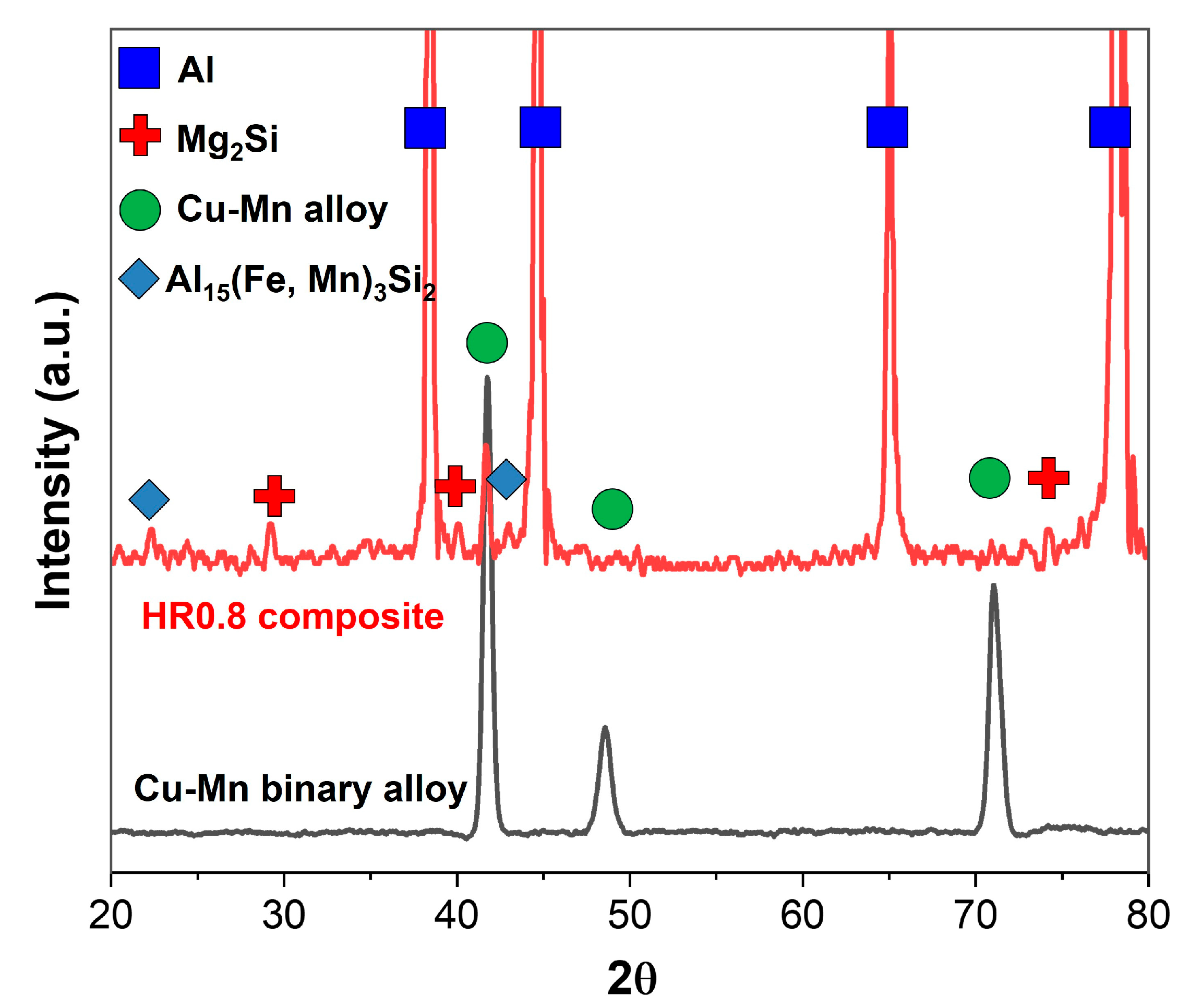
The newly developed composite was further subjected to XRD analysis to confirm the presence of different phases, and the results are shown in Figure 2. In order to investigate the stability of a Cu-Mn binary solid solution (hereinafter called the Cu-Mn binary phase) phase during the melting process, XRD analysis of the Cu-Mg binary solid solution alloy powders was also performed, revealing an FCC structure with a lattice parameter of 0.3732 nm [24]. The results confirmed that the HR0.8 composite consisted of α-Al-matrix, Mg2Si, Al15(Fe, Mn)3Si2, and Cu-Mn binary phases. The XRD pattern of the HR0.8 composite showed peaks at the same 2θ value, as was observed in the case of the XRD pattern of the Cu-Mn binary solid solution alloy. Therefore, these results confirmed that the Cu-Mn binary phase, which was dispersed in the form of a master alloy in the alloy’s melt, was maintained during the melting process. In addition, the Al15(Fe, Mn)3Si2 phase is expected to be formed by the partial reaction of the Cu-Mn binary phases with Al and Fe because of the presence of Fe in the aluminum melt.
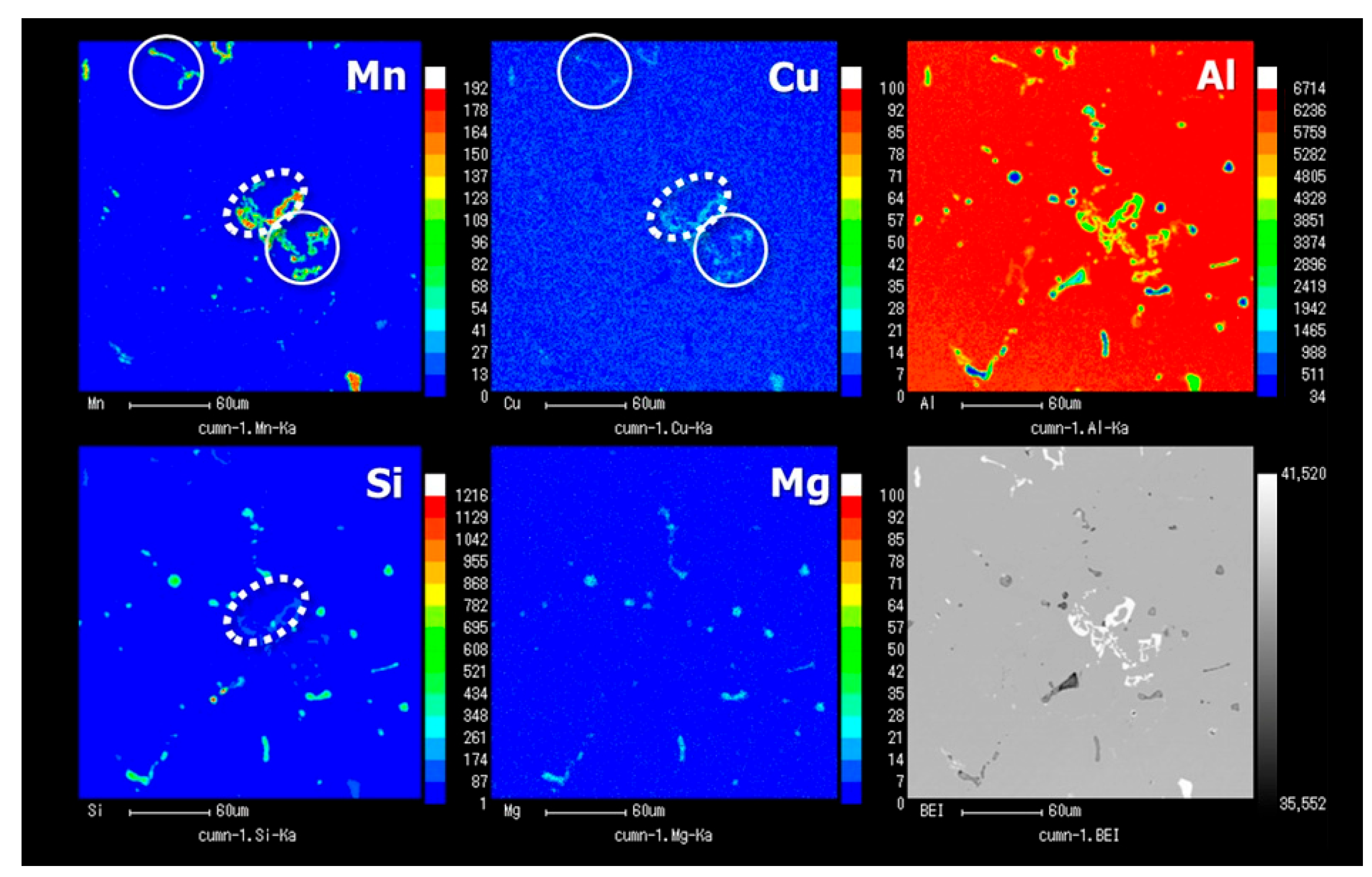
In order to further confirm the presence of the Cu-Mn binary phase and its distribution in the microstructure, the alloy was subjected to EPMA analysis, and the results are shown in Figure 3. EPMA analysis showed that some bright phases or parts of some of these phases consisted of Al, Fe, Mn, and Si (represented by dotted-line circles), similar to the ones shown in the EDS results (Figure 1c). Combining these results with the XRD results in Figure 2 reveals that these are Al15(Fe, Mn)3Si2 phases. On the other hand, by looking at the distribution of phases (marked by solid-line circles) right next to the abovementioned intermetallic compounds, as well as in other locations, it can be confirmed that there is no distribution of Si elements, whereas the distributions of Cu and Mn elements are relatively high, indicating a Cu-Mn binary solid solution phase. Again, combining the XRD results with the results obtained from EDS and EPMA analysis, it can be concluded that the Al15(Fe, Mn)3Si2 phase, the Cu-Mn binary phase, Mg2Si (as eutectic phases and nano-sized precipitates), and α-Al(Mn, Fe)Si dispersoids were present in the newly developed HR0.8 composite. Moreover, the presence of Al15(Fe, Mn)3Si2 and eutectic Mg2Si phases in close proximity to Cu-Mn phases reveals that particles of the latter phase in the melt acted as nucleation sites for the formation of former phases. As a result of this, the size and shape of the Al15(Fe, Mn)3Si2 phases were substantially different from those usually observed in Al-Si-Mg-(Fe)-based alloys [35,36,37,38,39]. The Al15(Fe, Mn)3Si2 phases were observed in the form of compact blocky or script-like morphologies, which are less detrimental to tensile properties than the plate-like morphology. This change in morphology may be attributed to the significant amount of manganese (Mn) present within the melt. The presence of Mn is known to alter the morphology of Fe-bearing phases, transforming them from needle-like structures to more benevolent forms such as compact blocky or script-like shapes [37]. Furthermore, recent research by Zhao et al. [39] has indicated that subjecting alloys containing Fe-rich phases to high-temperature solution heat treatments can lead to a significant transformation in their surface, transitioning from rough surfaces to spheroidized forms. It is reasonable to expect a similar mechanism to be at play in the current T6 heat-treated HR0.8 composite.
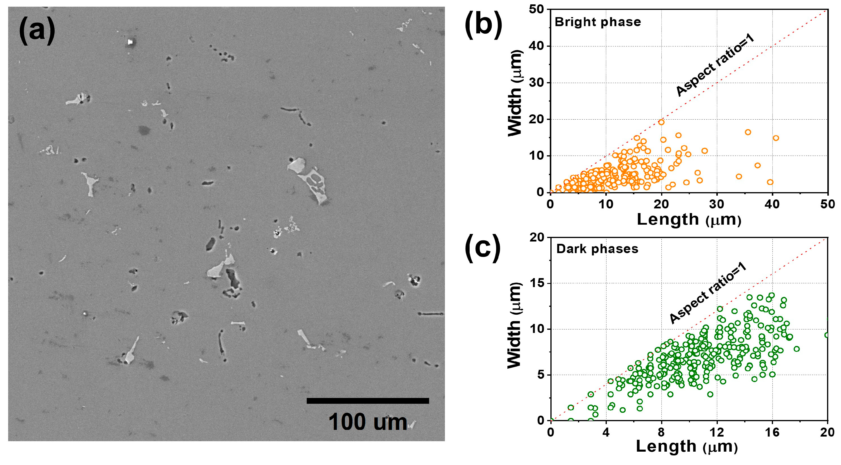
Quantitative analysis was employed to determine the size and distribution of the secondary phases present in the SEM microstructure of the HR0.8 composite, and the results are shown in Figure 4. It can be seen in Figure 4a that both the light phases (Cu-Mn and Al15(Fe, Mn)3Si2) and the dark phases (eutectic Mg2Si) are uniformly distributed in the alloy. The difference in size was large in the bright phases, with many irregular shapes (Figure 4b), whereas a relatively small size was observed for the eutectic Mg2Si (dark) phases, which had a relatively spherical shape (Figure 4c). Based on the EPMA results, it can be expected that the relatively large bright phases are Al15(Fe, Mn)3Si2. On the other hand, the bright phases were mostly in the form of rod-/plate-like shapes. In the case of the bright phases, the average size was 7.71 μm, with a fraction of 0.968 Vol.%. By contrast, the dark phases showed an average size of 8.0 μm and showed a fraction of 0.387 Vol.%. It is noteworthy that, within the master alloy, noticeable sizes (>10 μm) were identified for the Cu-Mn binary phases. This indicates that significant fragmentation or dissolution of Mn and Cu occurred from the Cu-Mn binary phases of the master alloy during the melting process. As a result, a relatively high amount of these elements was achieved in the Al matrix, as reported in the table in Figure 1. This dissolved Mn resulted in the formation of α-Al(Mn, Fe)Si dispersoids, as shown in Figure 1d,e, along with the formation of script-like Al15(Fe, Mn)3Si2 phases. However, the dissolved Cu is expected to have formed some nano-sized precipitates in addition to having a positive impact on the morphology of α-Al(Mn, Fe)Si dispersoids, as mentioned before [30].

3.2. Room- and High-Temperature Tensile Properties

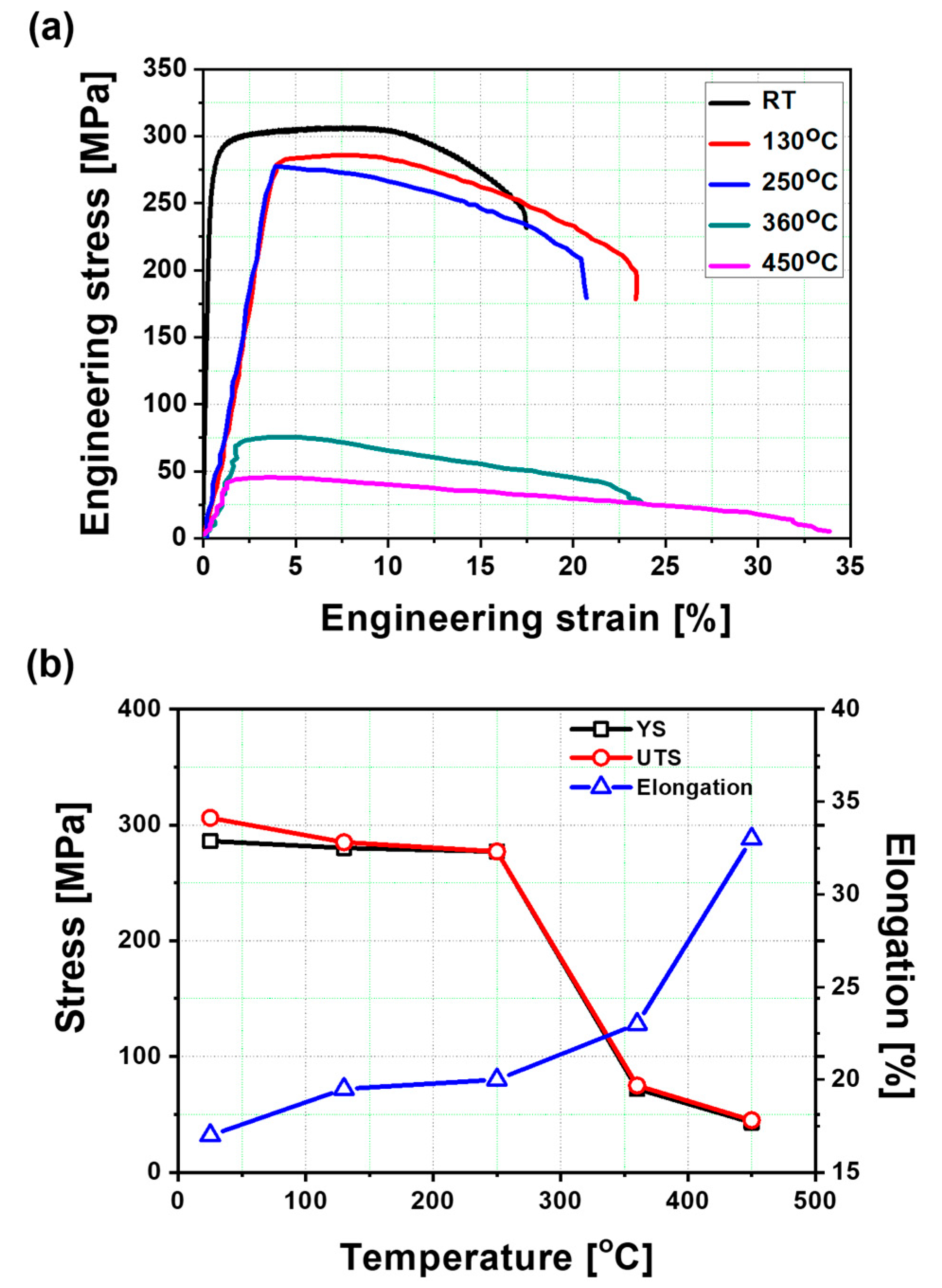
The stress–strain curves of the novel HR0.8 composite at various temperatures are shown in Figure 5a. The HR0.8 composite exhibited a yield strength (YS) of 287 MPa and an ultimate tensile strength (UTS) of 306 MPa, with an elongation (EL) of 17% at room temperature (RT). Such a strength and elongation combination has not been reported yet for Al-based casting alloys and heat-resistant alloys [40,41,42]. Moreover, despite the fact that increasing the temperature resulted in a reduction in YS and UTS and an increase in EL, as depicted in Figure 5b, the decrease in YS and UTS was insignificant compared to the majority of commercially available aluminum alloys [40], especially up to 250 °C. At 250 °C, the YS and UTS were ~277 MPa, and the EL to failure was 20%. The most common high-temperature Al alloys (such as A319) maintain their strength up until 150~200 °C and decrease in tensile strength significantly when the temperature is raised above 200 °C (Table 1). Therefore, from these results, it is clear that the novel HR0.8 composite showed excellent tensile properties at elevated temperatures (up to 250 °C) with superior ductility, which has not been achieved in conventional heat-resistant Al alloys. Nevertheless, when the temperature increased to more than 250 °C, the strength showed a rapid decrease. Similarly, EL slightly increased up until 250 °C, and then it increased rapidly to above 360 °C.
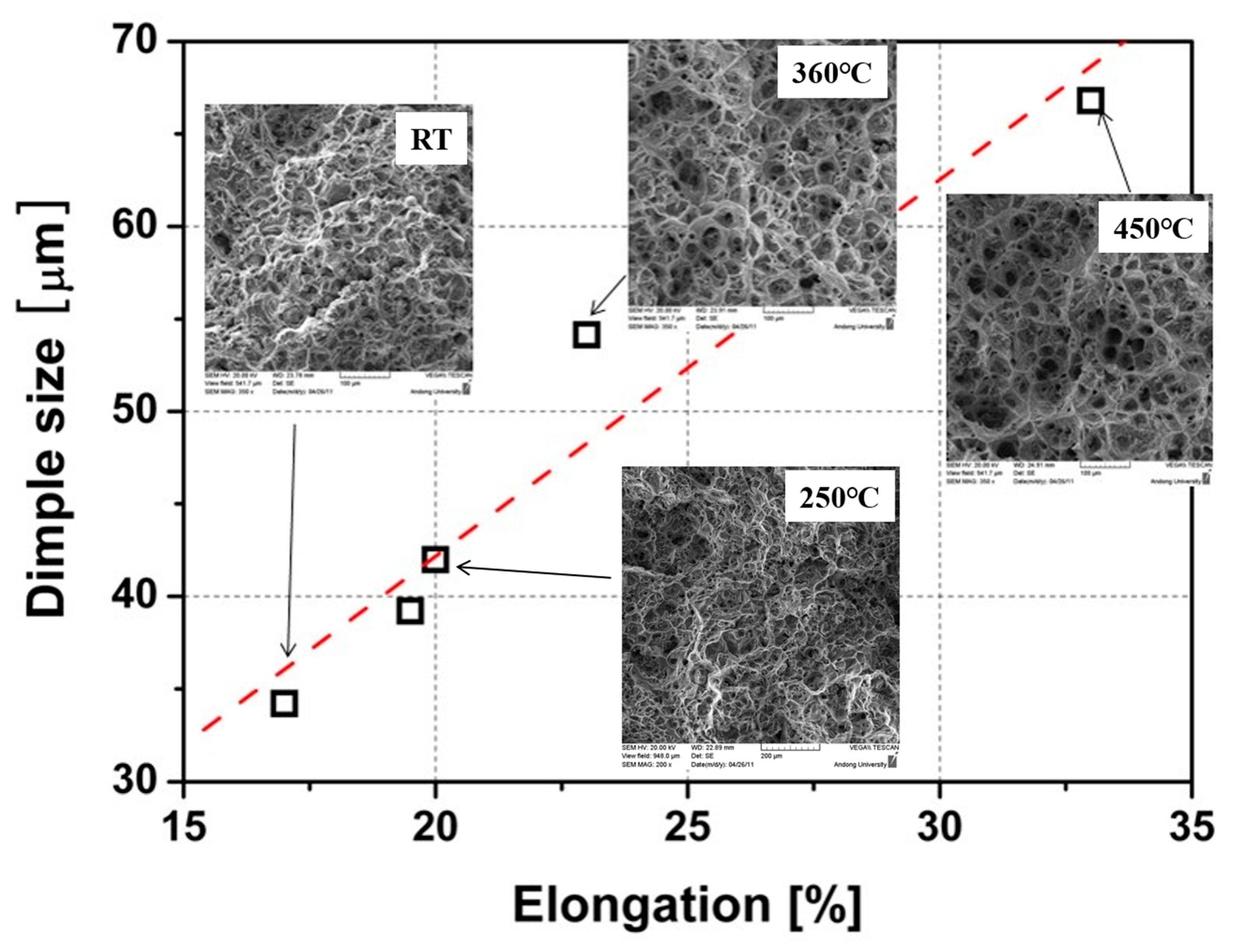
The fracture surface of the HR0.8 composite was analyzed to investigate the fracture mechanism, and the results are shown in Figure 6. The shape of the fracture surface does not change significantly until 250 °C (with elongation around 20%), and significant changes were only observed when the tensile test was conducted at temperatures of 360 °C and above, which is in good agreement with the result of a rapid increase in elongation and a decrease in strength (Figure 5a). The fracture surfaces at various temperatures consisted of dimples, indicating ductile fracture from room temperature to 450 °C. However, the size and depth of the dimple changed as the temperature increased, especially at temperatures over 360 °C, where the depth of the dimples became deeper and the dimple size increased significantly. Elongation and the size of the dimples showed a linear relationship (Figure 6); that is, the size of the dimples also greatly increases at a temperature where strength rapidly decreases and elongation rapidly increases.
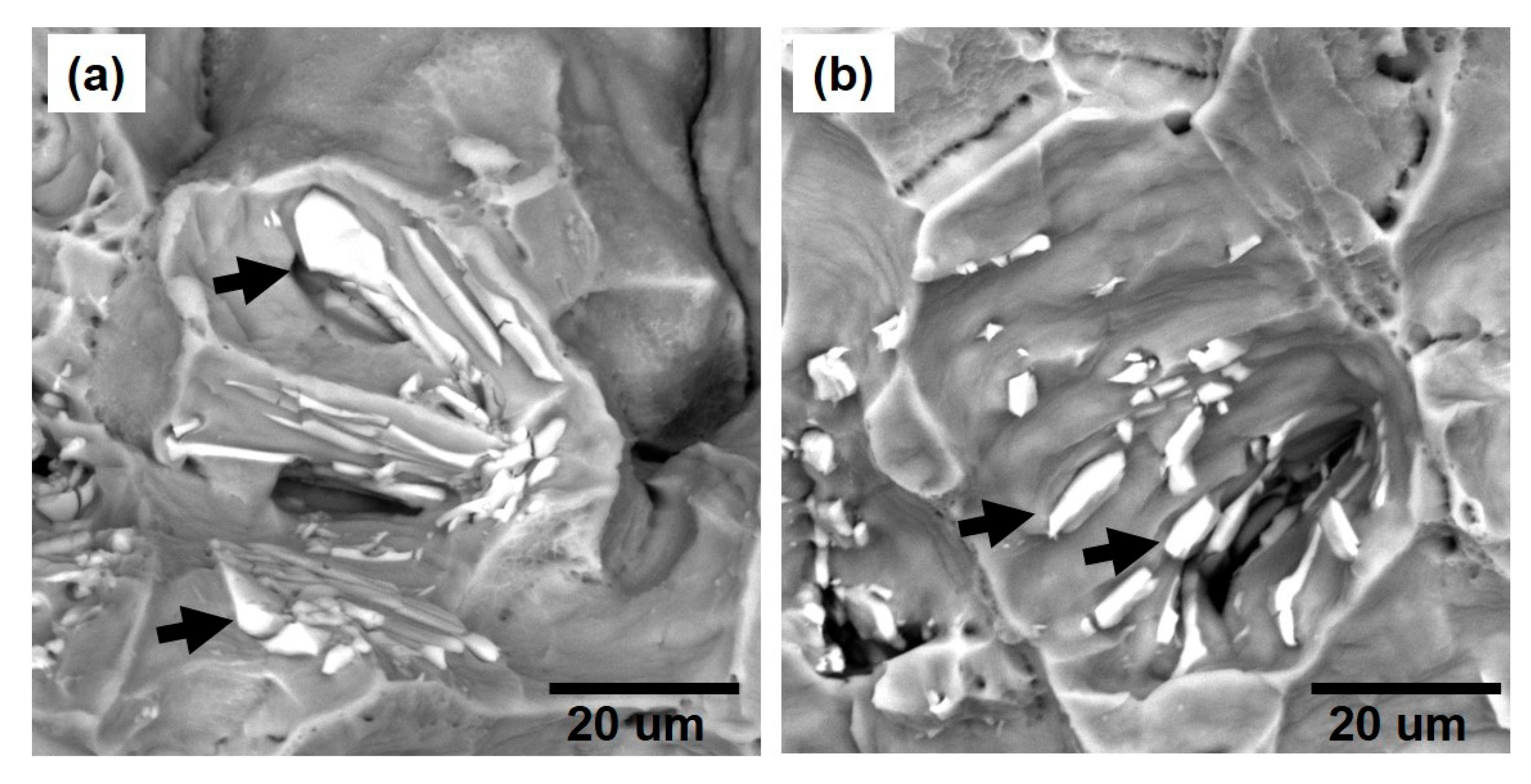
Figure 7a,b exhibits the results of fractography using a SEM. The images indicate the presence of bright phases (indicated with black arrows) within the majority of dimples on the fractured surface of the broken tensile specimen. These bright phases correspond to the Cu-Mn binary phases and a few large Al15(Fe, Mn)3Si2 phases. This observation suggests that these particles acted as the origin of the formation, growth, and merging of voids, ultimately leading to the creation of dimples under the influence of tensile forces. Furthermore, it is likely that these voids were generated through the separation of interfaces between these coarse particles and the Al matrix as well as the fracturing of these particles themselves.
In order to more closely examine the reinforcing mechanism of the secondary phases, broken tensile specimens were subjected to TEM analysis, as shown in Figure 8. It was observed that the Cu-Mn binary phases had the effect of limiting the movement of dislocations. The dislocations are piled up at the boundary between the particles and the matrix structure (Figure 8a,b). In Figure 8b, the yellow-dotted circle highlights the occurrence of fractures in certain sections of the mentioned particles. The presence of these particles resulted in the obstruction of dislocation movement, inducing localized stress concentrations. As a consequence, voids formed in order to alleviate the high stress concentrations. This observation emphasizes the notable role played by these phases in enhancing the fracture toughness of the composite. Moreover, the effects of grain boundaries on the mechanical properties of alloys are shown in Figure 8c, where it is observed that the density of dislocations is higher at the grain boundaries, showing the substantial contribution of grain boundary strengthening to the overall strength of the alloy. The TEM results presented in Figure 8d provide further insights into the influence of dispersoids on the strengthening of the HR0.8 composite. The absence of shearing within these dispersoids suggests that their contribution is primarily associated with the increased density of dislocations within the grains via Orowan strengthening.

3.3. High-Temperature High-Cycle Fatigue Properties

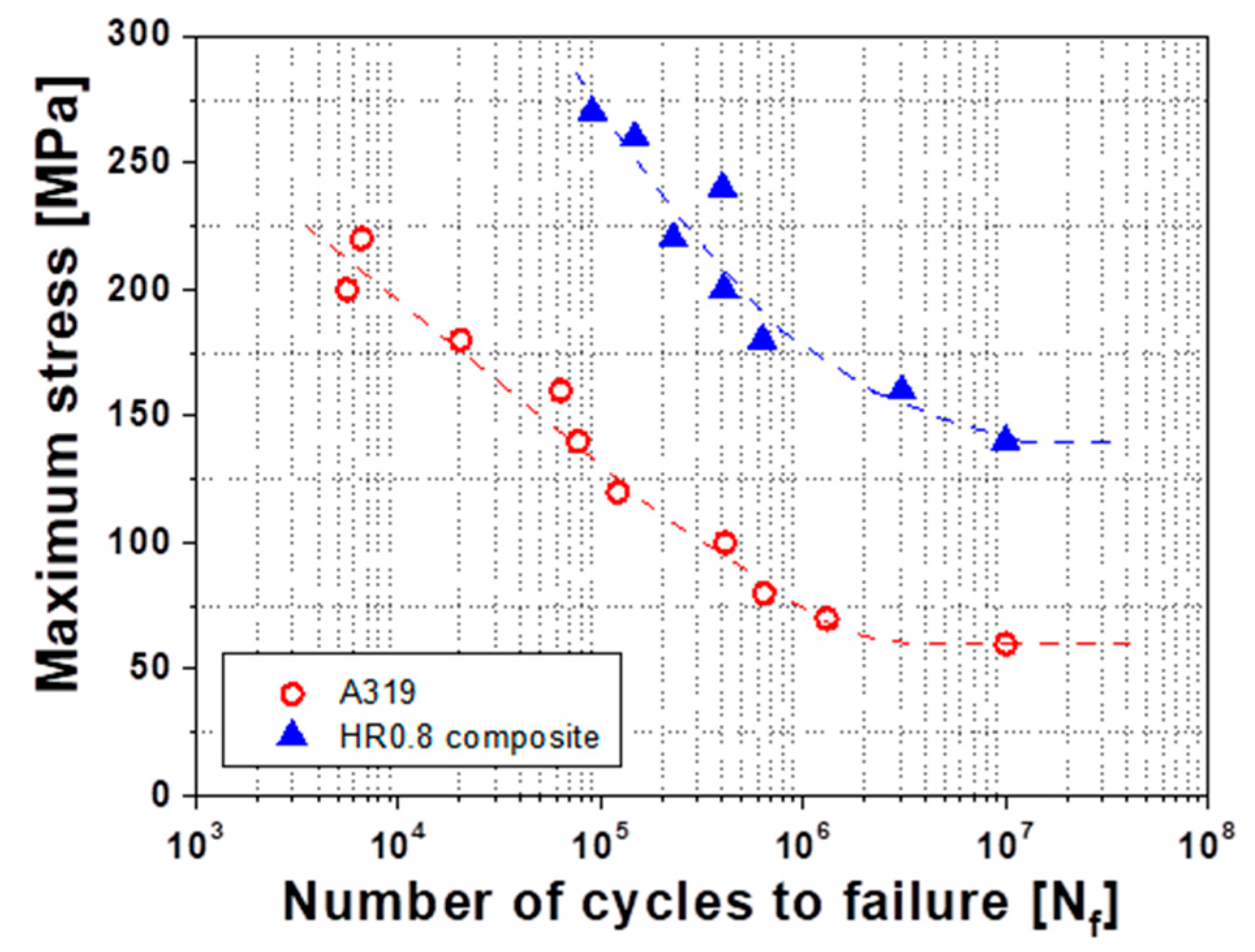
Figure 9 shows the results of the high-temperature high-cycle fatigue tests performed at 130 °C. It is clear from these results that the HR0.8 composite showed higher fatigue life than the A319 commercial alloy at all fatigue stress levels. The fatigue limit of the A319 alloy was about 60 MPa, whereas the fatigue limit of the HR0.8 composite was 140 MPa, demonstrating an approximate 2.3 times higher fatigue life than the A319 alloy.
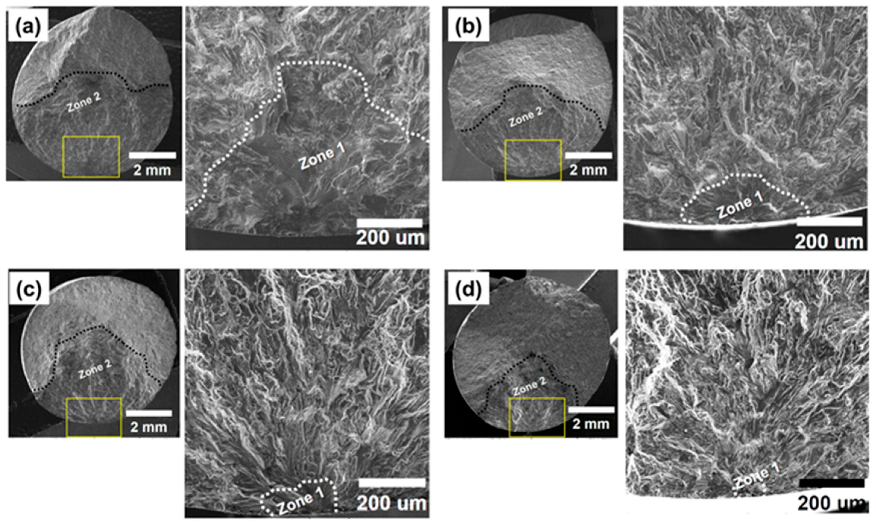
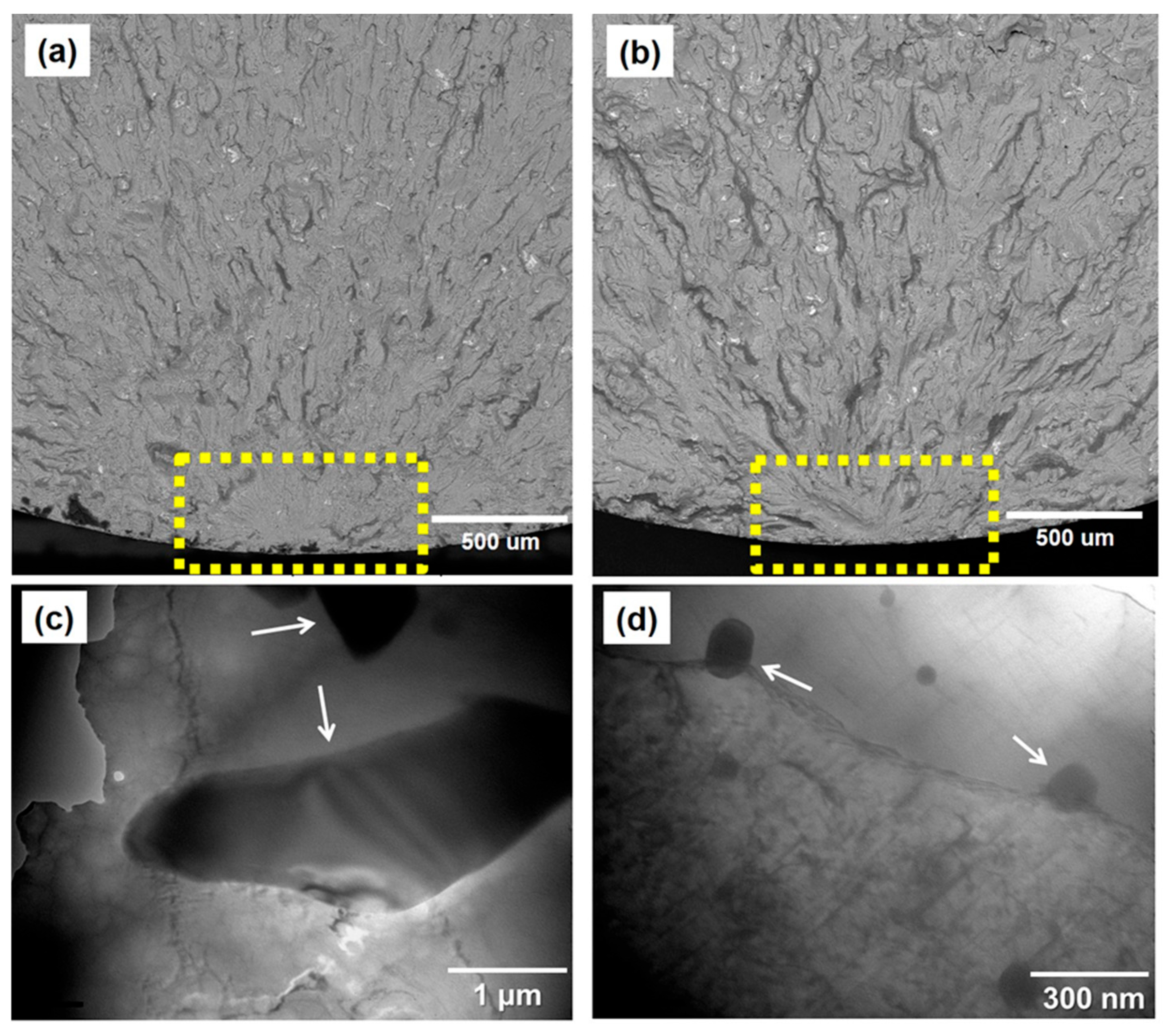
Figure 10 shows the fractured surfaces of the broken fatigue specimens, observed by SEM, with a maximum stress of 160 MPa (Figure 10a), 180 MPa (Figure 10b), 240 MPa (Figure 10c), and 260 MPa (Figure 10d). Zone 1 (showing the crack initiation area) and zone 2 (representing the crack propagation area) are shown in Figure 10, where the shape of zone 1 is relatively flat and the shape of zone 2 is rough. It is observed that as the fatigue stress increases, the area of zone 1 and total area of zone 1 + zone 2 both show a tendency to decrease.
In the fracture surfaces, which were broken under various fatigue stresses using the backscattered electron (BSE) mode in SEM (Figure 11a,b), inclusions, pores, and strengthening phases, which are generally the causes of fatigue crack initiation in aluminum casting alloys, were not observed at the initiation point [43,44,45,46]. Therefore, it is expected that the crack initiated through the formation of a persistent slip band upon cyclic loading [47].
To identify the effects of the secondary particles on the formation of the persistent slip band, the lower part of the fatigue crack initiation point (zone 1 in Figure 10) was observed using a TEM. As shown in Figure 11c, there was a reinforcement effect from the Cu-Mg binary phases (shown with white arrows) that hinders the movement of the dislocation, and these phases had no detachment from the interface or occurrence of shearing or cracking during fatigue deformation. As a result, they induced difficulty in the formation of a persistent slip band sufficient to generate cracks. Similarly, no shearing or cracking of the submicron-sized dispersoids (shown with white arrows) were observed (Figure 11d), which clearly shows their effectiveness at avoiding crack initiation [43,44,45,46].
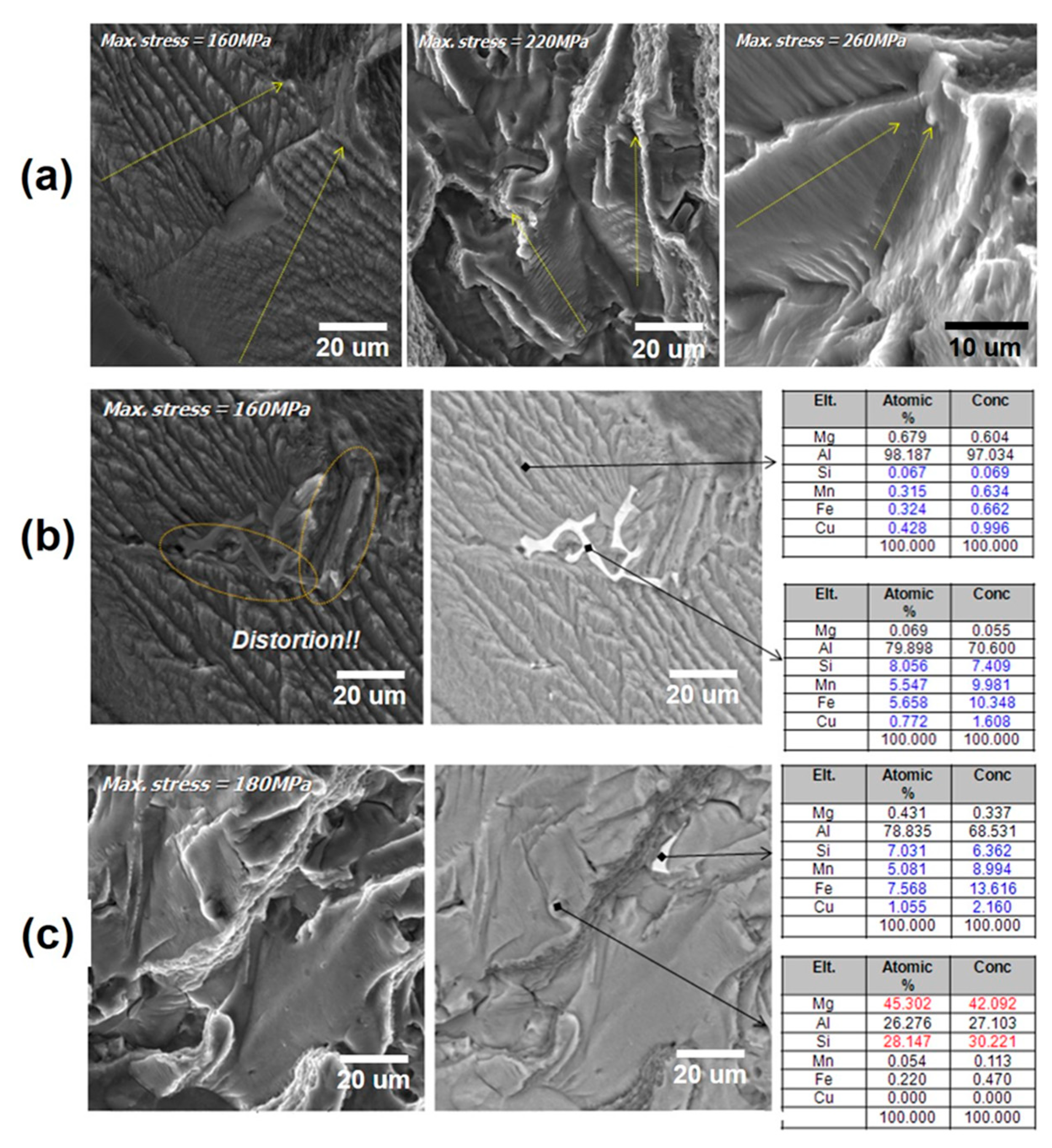
In order to investigate the effects of grain boundaries and secondary particles on the fatigue crack propagation behavior of the newly developed HR0.8 composite, broken fatigue specimens were subjected to further fractography (Figure 12). The effect of the grain boundaries is shown in Figure 12a, where it is observed that grain boundaries acted as a barrier and thus caused resistance to the growing cracks [43]. A change in the direction was observed when cracks moved from one grain to another. Furthermore, a notable variation in the width of striations was observed between different grains, which could be attributed to the non-uniform distribution of dispersoids and micron-sized phases within each grain. Nevertheless, as mentioned before, the average grain size of the HR0.8 composite is 98 μm, so the effect is considered to be insignificant compared to the submicron- and micron-sized particles within the grains. Figure 12b shows the effect of Cu-Mn and Al15(Fe, Mn)3Si2 particles on high-cycle fatigue crack growth. It was observed that when the growing cracks encountered these phases, the shape of the fracture surface was greatly distorted along the interface between the matrix and these phases, indicating their effectiveness in reducing the crack growth rate by changing the crack direction. Similar distortion was also observed around the eutectic Mg2Si phases (Figure 12c), showing their tendency to impede fatigue crack growth. However, the direction of propagation was not as greatly distorted as in the case of Cu-Mn and Al15(Fe, Mn)3Si2 particles. Therefore, it is expected that the cracks likely passed along the interface between the Mg2Si phase and the Al matrix. Considering the substantial number of micron-sized particles (Cu-Mn and Al15(Fe, Mn)3Si2), these phases are expected to have contributed significantly to reducing the crack propagation rate in zone 2 (Figure 10).

4. Discussion

4.1. Strengthening Mechanisms at Room Temperature (RT)

The yield strength at room temperature (RT) can be attributed to various strengthening mechanisms, which played their role. These mechanisms include the strengthening effect of nano-sized Mg2Si precipitates, submicron-sized α-Al(Mn, Fe)Si dispersoids, micron-sized particles such as eutectic Mg2Si phases, Cu-Mn binary phases, and Al15(Fe, Mn)3Si2 phases, as well as the influence of grain boundaries [40,41]. In the case of the HR0.8 composite developed in this study, it is observed that the material has a relatively large grain size of approximately 98 μm. This suggests that grain boundaries are not the primary strengthening mechanism at RT for this material. Instead, due to the abundance of nano-sized precipitates and their uniform distribution within the grains (as depicted in Figure 1e), it is expected that precipitation strengthening from these nano-sized precipitates played a crucial role in determining the overall strength of the composite at RT.
Another significant contribution to the overall strength of the composite can be attributed to the dispersoids of various sizes, which are heterogeneously distributed within the grains (as shown in Figure 1d). These dispersoids, with sizes of less than 1 μm, are expected to enhance the yield strength through Orowan strengthening, in conjunction with the Orowan strengthening effect of the nano-sized precipitates [40,41]. Furthermore, with regards to the micron-sized reinforced particles present in the Al matrix, previous studies [11,40,41] have reported that their strengthening mechanism is a combination of various factors, including load transfer and dislocation accumulation. Therefore, it is likely that these micron-sized particles, such as the Cu-Mn binary phases, Al15(Fe, Mn)3Si2, and eutectic Mg2Si phases, contributed to the overall strength of the newly developed composite through these mechanisms.
In comparison to commercial 6xxx.x series wrought alloys like 6066 and 6070, which have similar compositions to the current developed composite, the HR0.8 composite demonstrates a higher elongation but a lower yield strength [42]. The higher yield strength in these commercial alloys (>350 MPa) can be attributed to their relatively small grain size and higher amounts of Cu/Mn elements in comparison to the newly developed HR0.8 composite. On the other hand, the lower work hardening rate and ductility (10–12%) observed in the 6xxx.x series alloys are linked to the presence of precipitate-free zones near the grain boundaries. These soft zones promote the localization of plastic strain, leading to the initiation and propagation of cracks [48]. In the current study, the presence of coarse secondary particles, such as the Cu-Mn binary phases, Al15(Fe, Mn)3Si2, and eutectic Mg2Si phases, at and along the grain boundaries, combined with a significant amount of dispersoids, is expected to have reduced the formation of these soft zones. Consequently, the initiation and propagation of cracks were delayed, resulting in improved ductility in the HR0.8 composite.
The interfacial stability in particle-based Al composites is widely recognized as a crucial factor, with the presence of a solid solution at the interface reported to enhance effective load transfer and enable substantial deformation prior to cracking [11]. Therefore, among the micron-sized particles, the Cu-Mn binary phase likely contributed significantly in this regard due to its solid solution-based nature. Furthermore, Mn-added Fe-bearing phases have been found to exhibit higher strength and have a less detrimental impact on elongation than Mn-free Fe-rich phases. Previous studies have reported that both strength and elongation are increased by incorporating Mn+Fe in aluminum composites [35,36]. It has also been reported that the formation of a Fe/Mn solid solution at the interface of reinforced particles significantly improves load transfer and enhances resistance to cracking [11]. Additionally, the spheroidization of Fe-rich phases during heat treatment may contribute to improved elongation [39]. Therefore, the superior elongation observed in the newly developed composite can be attributed to these aforementioned factors. Moreover, a previous study [39] highlighted that after a certain amount of strain, the interface between Fe-bearing phases and the Al matrix experienced breakage. However, the matrix strengthening from the nano-sized precipitates was able to accommodate the damage and inhibit crack propagation. A similar mechanism is believed to have played a role in the current study, where the fracture of the coarse particles likely occurred when elongation reached ~10%, and, subsequently, the Orowan hardening effect from the nano-sized and submicron-sized particles maintained the strengthening, leading to higher ductility in the composite at RT.

4.2. Strengthening Mechanisms at Elevated Temperatures

When considering the thermal stability of the composite up to 250 °C, the dispersoids, Cu-Mn binary solid solution phases, and Al15(Fe, Mn)3Si2 phases are believed to have made a significant contribution to the overall strength of the composite. It has been reported that the nano-sized Mg-Si-based precipitates start to coarsen when the temperature exceeds 200 °C, leading to a decrease in strength [40]. However, the dispersoids, Cu-Mn binary solid solution phases, and Al15(Fe, Mn)3Si2 phases exhibit thermal stability up to that temperature, allowing the material to maintain its mechanical properties even at elevated temperatures. These stable particles present within the grains hinder dislocation motion and increase the shear force required for further deformation. Consequently, they enhance the resistance of the Al matrix against applied forces and elevated temperatures, thereby improving the thermal stability of the material [11,41]. Furthermore, these phases are expected to enhance the strength at elevated temperatures through the pinning effect on grain boundaries. It is worth noting that the strengthening effect of grain boundaries decreases significantly with increasing temperature [41]. Additionally, it is observed that the yield strength and ultimate tensile strength at 250 °C or higher temperatures remain relatively similar. This indicates that the dynamic restoration process becomes active once the yield stress is surpassed, resulting in dislocation annihilation/recrystallization and a decrease in work hardening.

4.3. Strengthening Mechanisms Under High-Temperature Cyclic Loading

As mentioned earlier, precipitate-free zones (PFZs) are known to exist in 6xxx.x series alloys near grain boundaries, making them susceptible to localized plastic deformation. These PFZs can accumulate damage during cyclic loading, creating conditions favorable for fatigue crack initiation [47]. In high-cycle fatigue, where the applied stress is significantly lower than the yield strength, plasticity localization in these regions and the subsequent initiation of a critical-sized crack contribute to most of the fatigue life. The presence of submicron dispersoids and micron-sized phases on or near grain boundaries is likely to improve the fatigue life of the novel composite. These particles may reinforce the PFZ regions or reduce the negative impact originating from them. By strengthening the PFZs or reducing the plasticity localization in those areas, the composite is expected to exhibit enhanced resistance to fatigue crack initiation. Moreover, as shown in Figure 12b, it has been observed that these micron-sized particles (Cu-Mn and Al15(Fe, Mn)3Si2) also contributed significantly to reducing the crack propagation rate in zone 2. Therefore, it can be concluded that the thermally stable micron-sized Cu-Mg solid solution phases and submicron-sized dispersoids contributed to enhancing the fatigue strength of the HR0.8 composite at elevated temperatures.

5. Conclusions

This study reported the development of a novel Al-1.1Si-1.0Mg-based composite reinforced by micron-sized Cu-Mn binary solid solution phases and submicron-sized α-Al(Mn,Fe)Si dispersoids. The newly designed composite was then subjected to various characterizations to comprehend the relationship between the mechanical properties and the microstructure. The main conclusions of this study are as follows:
  • Microstructure analysis confirmed the presence of micron-sized Cu-Mn binary, eutectic Mg2Si, and Al15(Fe, Mn)3Si2 phases, submicron-sized α-Al(Mn, Fe)Si dispersoids, and nano-sized precipitates in the microstructure of the composite in a T6 temper.
  • The newly developed composite demonstrated improved mechanical properties compared to commonly used heat-resistant Al alloys. At room temperature, it exhibits a yield strength (YS) of 287 MPa and a maximum tensile strength (TS) of 306 MPa, with an elongation of 17%, attributed mainly to Orowan strengthening from nano-sized precipitates and submicron dispersoids, along with load transfer and dislocation density strengthening from micron-sized Cu-Mn binary solid solution phases, and grain boundary strengthening.
  • Moreover, the novel composite maintained a YS of 277 MPa up to 250 °C, with a slight increase in elongation. The improved thermal stability is attributed to the presence of submicron dispersoids and micron-sized (Cu-Mn binary and Al15(Fe, Mn)3Si2) phases pinning the dislocations as well as grain boundaries.
  • The new composite also exhibited excellent high-temperature high-cycle fatigue properties and showed a high-cycle fatigue limit of 140 MPa at 130 °C, which is ~2.3 times higher than that of the A319 alloy. A fractography study revealed that the secondary particles hindered the movement of dislocations, thus delaying crack initiation under cyclic loading at high temperatures. Additionally, Cu-Mn binary and Al15(Fe, Mn)3Si2 phases were also found to be effective in reducing the crack propagation rate by hindering the movement of the propagated crack.

Author Contributions

Conceptualization, K.-S.K., S.-Y.S. and K.-A.L.; methodology, K.-S.K. and J.-P.K.; validation, A.W.S. and M.-S.J.; investigation, K.-S.K. and J.-P.K.; writing—original draft preparation, K.-S.K. and A.W.S.; writing—review and editing, K.-A.L.; visualization, M.-S.J.; supervision, K.-A.L. All authors have read and agreed to the published version of the manuscript.

Funding

This work was supported by a National Research Foundation of Korea (NRF) grant funded by the Korean Government (MSIT) (NRF-RS-2023-00281508) and a National Research Foundation of Korea (NRF) grant funded by the Korean government (MSIT) (No. 2022R1A5A1030054).

Data Availability Statement

The original contributions presented in this study are included in the article. Further inquiries can be directed to the corresponding author.

Acknowledgments

The authors sincerely thank the National Research Foundation of Korea (NRF) for supporting the research.

Conflicts of Interest

The authors declare no conflicts of interest.

Abbreviations

The following abbreviations are used in this manuscript:
AMCsAluminum matrix composites
HEAsHigh-entropy alloys
SEMScanning electron microscope
EDSEnergy dispersive spectroscopy
EPMAElectron probe micro analysis
TEMTransmission electron microscopy
YSYield strength
UTSUltimate tensile strength
ELElongation
RTRoom temperature
BSEBackscattered electron
PFZsPrecipitate-free zones

References

  1. Cai, Q.; Lordan, E.; Wang, S.; Liu, G.; Mendis, C.L.; Chang, I.T.H.; Ji, S. Die-Cast Multicomponent near-Eutectic and Hypoeutectic Al–Si–Ni–Fe–Mn Alloys: Microstructures and Mechanical Properties. Mater. Sci. Eng. A 2023, 872, 144977. [Google Scholar] [CrossRef]
  2. Zhou, Z.; Liu, X.; Le, P.; Liao, Y.; He, G.; Wang, Q.; He, Q. Effect of Heat Treatment and Loading Path on Non-Proportional Fatigue Behavior and Fracture Characteristics of an Al-Si Casting Alloy. J. Mater. Eng. Perform. 2023, 32, 4325–4337. [Google Scholar] [CrossRef]
  3. Lin, B.; Fan, T.; Li, H.; Zhao, Y.; Zhang, W.; Liu, K. Microstructure and High Temperature Tensile Properties of Al–Si–Cu–Mn–Fe Alloys Prepared by Semi-Solid Thixoforming. Trans. Nonferrous Met. Soc. China 2021, 31, 2232–2249. [Google Scholar] [CrossRef]
  4. Zhang, H.; Liu, Y.; Fan, T. Three-Dimensional Network Structure and Mechanical Properties of Al-Cu-Ni-Fe Cast Alloys with Gd Micro-Addition. Metall. Mater. Trans. A 2021, 52, 2613–2629. [Google Scholar] [CrossRef]
  5. Sun, J.; Zeng, G.; Rao, D.; Wang, Y.; Yang, Y.; Pan, L.; Hu, Z. Microstructure and Tensile Properties of a Cast Eutectic Al–Si–Cu Alloy Modified by Zr and V. Met. Mater. Int. 2021, 27, 5436–5449. [Google Scholar] [CrossRef]
  6. Limodin, N.; Dahdah, N.; Wang, L.; El Bartali, A.; Witz, J.-F.; Buffiere, J.-Y.; Charkaluk, E. Characterisation of 3D Strain Heterogeneity at the Microstructure Scale during Low Cycle Fatigue of an AlSi7Cu3Mg Alloy at 250 °C. Int. J. Fatigue 2023, 172, 107476. [Google Scholar] [CrossRef]
  7. Mohammed, A.A. Original Articles. Rev. Afr. Polit. Econ. 2003, 30, 479–510. [Google Scholar] [CrossRef]
  8. Malaki, M.; Tehrani, A.F.; Niroumand, B. Fatgiue Behavior of Metal Matrix Nanocomposites. Ceram. Int. 2020, 46, 23326–23336. [Google Scholar] [CrossRef]
  9. Azadi, M.; Bahmanabadi, H.; Gruen, F.; Winter, G. Evaluation of Tensile and Low-Cycle Fatigue Properties at Elevated Temperatures in Piston Aluminum-Silicon Alloys with and without Nano-Clay-Particles and Heat Treatment. Mater. Sci. Eng. A 2020, 788, 139497. [Google Scholar] [CrossRef]
  10. Shettar, M.; Sharma, S.; M C, G.; H M, V.; Ranjan, R.; Doddapaneni, S. Individual and Combined Effects of Reinforcements on Fractured Surface of Artificially Aged Al6061 Hybrid Composites. J. Compos. Sci. 2023, 7, 91. [Google Scholar] [CrossRef]
  11. Ren, L.; Zhao, K.; Gao, T.; Liu, G.; Sun, Q.; Liu, X.; Liu, S. A New Measure to Enhance the Heat-Resistant (4TiC + 5AlN)/Al Composite by Multi-Scale Fe/Mn Enrichment Effect. J. Alloys Compd. 2023, 952, 170019. [Google Scholar] [CrossRef]
  12. Azizi, A.; Zangeneh, S.; Mojtahedi, M.; Rasaee, S. Hot Deformation Behavior and Microstructure of Ni-Cu Rich Al-Si AA4032 Alloy. J. Alloys Compd. 2023, 940, 168934. [Google Scholar] [CrossRef]
  13. Sun, Y.; Li, C.; Zhou, Z.; An, R.; Yu, L.; Liu, Y. The Strengthening Role of Micro-Sized Phases and Nano-Precipitates in Al–Mg2Si–Cu(–Ni) Alloys at 25 °C and 350 °C. J. Mater. Res. Technol. 2023, 24, 2514–2521. [Google Scholar] [CrossRef]
  14. Zohoor, M.; Besharati Givi, M.K.; Salami, P. Effect of Processing Parameters on Fabrication of Al–Mg/Cu Composites via Friction Stir Processing. Mater. Des. 2012, 39, 358–365. [Google Scholar] [CrossRef]
  15. Farajollahi, R.; Jamshidi Aval, H.; Jamaati, R. Evaluating of the Microstructure, Texture, and Mechanical Properties of AA2024-Al3NiCu Composites Fabricated by the Stir Casting Process. CIRP J. Manuf. Sci. Technol. 2022, 37, 204–218. [Google Scholar] [CrossRef]
  16. Selvakumar, S.; Dinaharan, I.; Palanivel, R.; Babu, B.G. Development of Stainless Steel Particulate Reinforced AA6082 Aluminum Matrix Composites with Enhanced Ductility Using Friction Stir Processing. Mater. Sci. Eng. A 2017, 685, 317–326. [Google Scholar] [CrossRef]
  17. Georgarakis, K.; Dudina, D.V.; Kvashnin, V.I. Metallic Glass-Reinforced Metal Matrix Composites: Design, Interfaces and Properties. Materials 2022, 15, 8278. [Google Scholar] [CrossRef]
  18. Rezaei, M.R.; Albooyeh, A.; Shayestefar, M.; Shiraghaei, H. Microstructural and Mechanical Properties of a Novel Al-Based Hybrid Composite Reinforced with Metallic Glass and Ceramic Particles. Mater. Sci. Eng. A 2020, 786, 139440. [Google Scholar] [CrossRef]
  19. Luo, K.; Xiong, H.; Zhang, Y.; Gu, H.; Li, Z.; Kong, C.; Yu, H. AA1050 Metal Matrix Composites Reinforced by High-Entropy Alloy Particles via Stir Casting and Subsequent Rolling. J. Alloys Compd. 2022, 893, 162370. [Google Scholar] [CrossRef]
  20. Liu, Y.; Chen, J.; Li, Z.; Wang, X.; Fan, X.; Liu, J. Formation of Transition Layer and Its Effect on Mechanical Properties of AlCoCrFeNi High-Entropy Alloy/Al Composites. J. Alloys Compd. 2019, 780, 558–564. [Google Scholar] [CrossRef]
  21. Yang, X.; Zhang, H.; Dong, P.; Yan, Z.; Wang, W. A Study on the Formation of Multiple Intermetallic Compounds of Friction Stir Processed High Entropy Alloy Particles Reinforced Al Matrix Composites. Mater. Charact. 2022, 183, 111646. [Google Scholar] [CrossRef]
  22. Wu, C.-Y.; Wu, C.-T.; Lee, W.-H.; Chang, S.-C.; Wang, Y.-L. A Study on Annealing Mechanisms with Different Manganese Contents in CuMn Alloy. J. Alloys Compd. 2012, 542, 118–123. [Google Scholar] [CrossRef]
  23. Lee, H.-Y.; He, C.-W.; Lee, Y.-C.; Wu, D.-C. A Study on the Characteristics of Cu–Mn–Dy Alloy Resistive Thin Films. Coatings 2019, 9, 118. [Google Scholar] [CrossRef]
  24. Zhang, S.; Guo, X.P.; Tang, Y.; You, W.X.; Xu, Y.G. Microstructure and Properties of Mn-Cu-Based Damping Alloys Prepared by Ball Milling and Hot-Press Sintering. J. Mater. Eng. Perform. 2019, 28, 2641–2648. [Google Scholar] [CrossRef]
  25. Chen, C.; Li, J.; Ji, P.; Guo, W.; Liu, B.; Xue, H.; Li, X.; Zhao, D.; Yin, F. Microstructure and Damping Property of Mn-Cu Damping Alloy by Induction Brazing and Different Heat Treating. Mater. Lett. 2023, 330, 133312. [Google Scholar] [CrossRef]
  26. ASTM E8/E8M-21; Standard Test Methods for Tension Testing of Metallic Materials. ASTM International: West Conshohocken, PA, USA, 2021.
  27. ASTM E21-20; Standard Test Methods for Elevated Temperature Tension Tests of Metallic Materials. ASTM International: West Conshohocken, PA, USA, 2020.
  28. ASTM E466-21; Standard Practice for Conducting Force Controlled Constant Amplitude Axial Fatigue Tests of Metallic Materials. ASTM International: West Conshohocken, PA, USA, 2021.
  29. ASTM B26/B26M-18e1; Standard Specification for Aluminum-Alloy Sand Castings. ASTM International: West Conshohocken, PA, USA, 2018.
  30. Liu, F.-Z.; Qin, J.; Li, Z.; Yu, C.-B.; Zhu, X.; Nagaumi, H.; Zhang, B. Precipitation of Dispersoids in Al–Mg–Si Alloys with Cu Addition. J. Mater. Res. Technol. 2021, 14, 3134–3139. [Google Scholar] [CrossRef]
  31. Zandbergen, M.W.; Xu, Q.; Cerezo, A.; Smith, G.D.W. Study of Precipitation in Al–Mg–Si Alloys by Atom Probe Tomography I. Microstructural Changes as a Function of Ageing Temperature. Acta Mater. 2015, 101, 136–148. [Google Scholar] [CrossRef]
  32. Baruah, M.; Borah, A. Processing and Precipitation Strengthening of 6xxx Series Aluminium Alloys: A Review. Int. J. Mater. Sci. 2020, 1, 40–48. [Google Scholar] [CrossRef]
  33. Shah, A.W.; Ha, S.-H.; Yoon, Y.-O.; Kim, S.K. Heat Treatment of Al–Mg–Si–Mn Alloys with Varying Mg/Si Ratio. In Light Metals 2022; Springer: Cham, Switzerland, 2022; pp. 199–206. [Google Scholar]
  34. Asghar, G.; Peng, L.; Fu, P.; Yuan, L.; Liu, Y. Role of Mg2Si Precipitates Size in Determining the Ductility of A357 Cast Alloy. Mater. Des. 2020, 186, 108280. [Google Scholar] [CrossRef]
  35. Taylor, J.A. Iron-Containing Intermetallic Phases in Al-Si Based Casting Alloys. Procedia Mater. Sci. 2012, 1, 19–33. [Google Scholar] [CrossRef]
  36. Chanyathunyaroj, K.; Patakham, U.; Kou, S.; Limmaneevichitr, C. Microstructural Evolution of Iron-Rich Intermetallic Compounds in Scandium Modified Al-7Si-0.3Mg Alloys. J. Alloys Compd. 2017, 692, 865–875. [Google Scholar] [CrossRef]
  37. Puncreobutr, C.; Phillion, A.B.; Fife, J.L.; Rockett, P.; Horsfield, A.P.; Lee, P.D. In Situ Quantification of the Nucleation and Growth of Fe-Rich Intermetallics during Al Alloy Solidification. Acta Mater. 2014, 79, 292–303. [Google Scholar] [CrossRef]
  38. Xu, S.; Khanlari, K.; Lin, B.; Fan, T.; Xia, S.; Achouri, I.E.; Zhang, W.; Jiang, Y. Effects of Fe-Addition as a Beneficial Modifying Element on the Microstructure and Mechanical Properties of an Al–Si–Cu–Mg–Ni–Mn Piston Alloy. Metallogr. Microstruct. Anal. 2023, 12, 401–412. [Google Scholar] [CrossRef]
  39. Zhao, Y.; Song, D.; Wu, S.; Xie, S.; Wang, H.; Wang, M.; Zhang, W.; Sun, Z.; Ke, Y.; Wang, S.; et al. Influence of Fe-Rich Phases and Precipitates on the Mechanical Behaviour of Al-Cu-Mn-Fe-Sc-Zr Alloys Studied by Synchrotron X-Ray and Neutron. J. Mater. Sci. Technol. 2023, 158, 226–241. [Google Scholar] [CrossRef]
  40. Du, H.; Zhang, S.; Zhang, B.; Tao, X.; Yao, Z.; Belov, N.; van der Zwaag, S.; Liu, Z. Ca-Modified Al–Mg–Sc Alloy with High Strength at Elevated Temperatures Due to a Hierarchical Microstructure. J. Mater. Sci. 2021, 56, 16145–16157. [Google Scholar] [CrossRef]
  41. Li, J.; Zhao, K.; Ren, L.; Xie, K.; Li, D.; Liu, S.; Liu, X. Microstructure Evolution, Mechanical Properties, and Strengthening Mechanisms of Heat-Resistant Al-Based Composite Reinforced by a Combination of AlN and TiN Particles. J. Mater. Res. Technol. 2023, 24, 5628–5641. [Google Scholar] [CrossRef]
  42. Hatch, J.E. (Ed.) Aluminum: Properties and Physical Metallurgy; ASM International: Metals Park, OH, USA, 1984. [Google Scholar]
  43. Wang, B.B.; An, X.H.; Xue, P.; Liu, F.C.; Ni, D.R.; Xiao, B.L.; Liu, Y.D.; Ma, Z.Y. Grain Size Effects on High Cycle Fatigue Behaviors of Pure Aluminum. Int. J. Fatigue 2023, 170, 107556. [Google Scholar] [CrossRef]
  44. He, C.; Wei, J.; Li, Y.; Zhang, Z.; Tian, N.; Qin, G.; Zuo, L. Improvement of Microstructure and Fatigue Performance of Wire-Arc Additive Manufactured 4043 Aluminum Alloy Assisted by Interlayer Friction Stir Processing. J. Mater. Sci. Technol. 2023, 133, 183–194. [Google Scholar] [CrossRef]
  45. Sepe, R.; Giannella, V.; Razavi, N.; Berto, F. Characterization of Static, Fatigue and Fracture Behaviour of the Aluminium-Lithium Alloy Al-Li 2198-T851. Int. J. Fatigue 2023, 166, 107265. [Google Scholar] [CrossRef]
  46. Vysotskiy, I.; Malopheyev, S.; Rahimi, S.; Mironov, S.; Kaibyshev, R. Unusual Fatigue Behavior of Friction-Stir Welded Al–Mg–Si Alloy. Mater. Sci. Eng. A 2019, 760, 277–286. [Google Scholar] [CrossRef]
  47. Zhang, Q.; Zhu, Y.; Gao, X.; Wu, Y.; Hutchinson, C. Training High-Strength Aluminum Alloys to Withstand Fatigue. Nat. Commun. 2020, 11, 5198. [Google Scholar] [CrossRef] [PubMed]
  48. Hagen, A.B.; Wenner, S.; Bjørge, R.; Wan, D.; Marioara, C.D.; Holmestad, R.; Ringdalen, I.G. Local Mechanical Properties and Precipitation Inhomogeneity in Large-Grained Al–Mg–Si Alloy. Mater. Sci. Eng. A 2023, 872, 144222. [Google Scholar] [CrossRef]
Figure 1. (ac) OM micrograph showing the grain structure, (d) SEM micrographs showing the second phases, (e) SEM micrographs showing the second phases and presents the EDS results for the points indicated in images, and (f,g) TEM micrographs showing submicron dispersoids (black arrows) and nano-sized precipitates (white arrows) of the newly developed HR0.8 composite in a T6 temper.
Metals 15 00958 g001
Figure 2. X-ray diffraction analysis results of Cu-Mn binary solid solution alloy powders and the newly developed HR0.8 composite.
Metals 15 00958 g002
Figure 3. EPMA analysis results showing the distribution of various elements in the novel HR0.8 composite.
Metals 15 00958 g003
Figure 4. (a) SEM micrograph of the newly developed HR0.8 composite. The accompanying graphs, (b) and (c), present the fraction and size distribution of the bright phases (comprised of the Cu-Mn binary and Al15(Fe, Mn)3Si2) and the dark phases (eutectic Mg2Si), respectively.
Metals 15 00958 g004
Figure 5. Tensile stress–strain curves (a), and the corresponding tensile properties (b) of the novel HR0.8 composite at different temperatures.
Metals 15 00958 g005
Figure 6. The variation in the average size of dimples as a function of the temperature at which the tensile test was conducted.
Metals 15 00958 g006
Figure 7. SEM fractography images (a,b) of the broken tensile specimens of the HR0.8 composite. The images reveal the presence of bright phases, namely Cu-Mn binary and Al15(Fe, Mn)3Si2, on the surfaces of the fractures.
Metals 15 00958 g007
Figure 8. TEM bright field images (a,b), which demonstrate the accumulation of dislocations at the interface between the Al matrix and the Cu-Mn binary and Al15(Fe, Mn)3Si2 particles. And highlights the occurrence of fractures in certain sections of the mentioned particle (yellow circle). Furthermore, TEM bright field images of the fractured surface of the broken tensile specimen exhibit a relatively high density of dislocations at the grain boundaries (c,d) of dispersoids (black arrow), without any evidence of debonding or shearing.
Metals 15 00958 g008
Figure 9. High-temperature high-cycle fatigue results of the HR0.8 composite and the conventional Al alloy (A319) are presented for when the fatigue tests were conducted at a temperature of 130 °C.
Metals 15 00958 g009
Figure 10. SEM fractography micrographs showing the fatigue fractured surfaces of broken fatigue specimens with a maximum stress of (a) 160 MPa, (b) 180 MPa, (c) 240 MPa, and (d) 260 MPa. And Zone 1 area has been indicated at each specimens (yellow boxes).
Metals 15 00958 g010
Figure 11. SEM fractography analysis of fatigued specimens subjected to maximum stresses of (a) 180 MPa and (b) 240 MPa. The crack initiation areas are highlighted using yellow-dotted boxes. Moreover, TEM bright field images captured from the sites where fatigue cracks originated revealed the presence of intact (c) Cu-Mn binary particles (arrows) and (d) nano-sized particles (arrows).
Metals 15 00958 g011
Figure 12. SEM fractography analysis of fatigued specimens reveals the impact of different factors on fatigue crack propagation. These factors include (a) the influence of grain boundaries (arrows), (b) the distortion of Cu-Mn binary-Al15(Fe, Mn)3Si2 particles (circles), and (c) the influence of eutectic Mg2Si particles on the propagation of fatigue cracks.
Metals 15 00958 g012
Table 1. Comparison of tensile properties of the newly developed HR0.8 composite with the A319 commercial alloy at various temperatures.
Yield Strength (MPa)Tensile Strength (MPa)Elongation (%)
A319HR0.8A319HR0.8A319HR0.8
R.T155 ± 6.9286 ± 10.1210 ± 15.1306 ± 16.12 ± 0.417 ± 3.0
130 °C157 ± 5.1280 ± 8.5225 ± 12.5285 ± 15.23 ± 0.719.5 ± 2.5
250 °C150 ± 2.8277 ± 6.8160 ± 13.5277 ± 10.52 ± 0.420 ± 3.1
Disclaimer/Publisher’s Note: The statements, opinions and data contained in all publications are solely those of the individual author(s) and contributor(s) and not of MDPI and/or the editor(s). MDPI and/or the editor(s) disclaim responsibility for any injury to people or property resulting from any ideas, methods, instructions or products referred to in the content.