Article

High-Temperature Mechanical Properties and the Portevin–Le Chatelier Effect for Wire Arc Additively Manufactured Inconel 718 Superalloy

1
School of Science, Harbin Institute of Technology, Shenzhen 518055, China
2
School of Materials Science and Engineering, Harbin Institute of Technology, Shenzhen 518055, China
3
College of Aerospace Science and Engineering, National University of Defense Technology, Changsha 410073, China
4
Institute of Intelligent Manufacturing Technology, Shenzhen Polytechnic University, Shenzhen 518055, China
5
Beijing GAONA Materials & Technology Co., Ltd., Beijing 100081, China
*
Authors to whom correspondence should be addressed.
Metals 2025, 15(9), 949; https://doi.org/10.3390/met15090949 (registering DOI)
Submission received: 16 July 2025 / Revised: 10 August 2025 / Accepted: 18 August 2025 / Published: 27 August 2025

Abstract

In this study, high-temperature uniaxial tensile tests were performed on IN718 superalloy samples fabricated using Wire Arc Additive Manufacturing (WAAM) and compared to wrought IN718 superalloy samples. The mechanical properties and Portevin–Le Chatelier (PLC) behavior of WAAM IN718 were analyzed, with particular attention paid to its anisotropy and differences from its wrought counterpart. WAAM specimens were obtained from three distinct orientations within the printed blocks. The results indicated that WAAM IN718 exhibited a higher yield strength but reduced failure elongation compared to wrought IN718. Among the WAAM samples, the yield strength was highest in the transverse direction, followed by the in-depth direction, and lowest in the growth direction. Post-aging treatment significantly increased the yield strength of WAAM IN718. WAAM IN718 showed a larger critical strain for the onset of serrated flow and smaller stress drop amplitudes compared to wrought IN718 under the PLC effect. Furthermore, as the strain rate decreased, PLC serrations in WAAM specimens from the in-depth direction transitioned from type A to type C. Conversely, specimens from the growth direction maintained type B serrations at a strain rate of 10 4 s 1 . This study also examined potential factors influencing the differences in PLC behavior and conducted an analysis of the fracture surfaces across various specimens.

1. Introduction

Inconel 718 (IN718), an alloy based on nickel and iron, exhibits excellent corrosion resistance [1] and mechanical performance up to a temperature of approximately 650 °C [2], all at a reasonable cost. Consequently, it finds extensive applications in high-temperature environments such as aircraft engines, nuclear reactors, power plants, and petrochemical equipment [3,4]. Additive manufacturing (AM) technology possesses the capability to overcome geometric constraints in the production of intricate structural components, thereby significantly expanding the possibilities for mechanical design and materials processing [5]. Due to the excellent weldability of IN718 alloy [6], the academic community is extensively exploring the use of AM techniques to produce IN718 alloy components, aiming to replace the traditional casting–forging–heat treatment–machining process [7,8,9,10,11].
Currently, the technologies available for additive manufacturing of IN718 alloy include Powder Bed Fusion–Laser Beam (PBF-LB), Powder Bed Fusion–Electron Beam (PBF-EB), Wire Arc Additive Manufacturing (WAAM), and others. The PBF-LB and PBF-EB techniques have been widely employed for smaller IN718 components [12,13]. By optimizing parameters such as powder size, laser power, and scan speeds, and implementing an appropriate heat treatment after PBF-LB manufacturing, the mechanical properties of samples produced by laser beam melting can rival those of their conventionally wrought IN718 counterparts [14]. However, the PBF-LB and PBF-EB techniques are both limited by product size while also lacking advantages in terms of processing speed and production cost. In contrast, the wire and arc additive manufacturing (WAAM) technique offers a groundbreaking solution to address these challenges [15,16,17]. WAAM involves layer-by-layer deposition of metal wire onto a substrate through a simultaneous electric arc melting and deposition process [18]. Recent research indicates that in-process thermo-mechanical processing (rolling) can enhance the mechanical properties of WAAM-fabricated IN718, even surpassing those of the conventionally wrought IN718 alloy [19]. In recent years, WAAM has made significant progress in terms of defect control and performance improvement [20,21,22]. Therefore, this technology exhibits great potential for application across various fields.
The mechanical properties of as-deposited and heat-treated WAAM IN718 have been previously reported by researchers [23,24,25]. These studies indicate that WAAM IN718 exhibits comparable ultimate tensile strength (UTS), 0.2 % yield strength, and elongation performance to conventionally wrought IN718. However, the mechanical properties of WAAM materials vary in different directions due to the anisotropic nature of their microstructure [26,27,28]. For instance, refs. [29,30] found that vertical direction specimens of WAAM low-carbon high-strength steel exhibit relatively inferior mechanical and fracture properties compared to horizontal direction specimens, which was attributed to their stronger microstructural inhomogeneity along the horizontal direction. In the WAAM IN718 specimens, a similar situation is observed: the strength and ductility of the specimens in the horizontal direction are slightly higher than those in the vertical direction. It is worth noting that previous studies on the anisotropy of wall-shaped WAAM IN718 components have typically only distinguished between the horizontal and vertical directions, without further differentiating between the transverse direction (TD) and the in-depth direction (ID) within the horizontal plane. In modeling work for additive manufacturing process optimization and residual stress simulations, accurate constitutive parameters are required to improve model fidelity [31,32,33,34]. In this context, the present study quantifies the anisotropy of material behavior in all three orientations, thereby filling the gap in the literature where previous work has characterized only two directions while neglecting the third.
Portevin–Le Chatelier (PLC) effects have been observed in IN718 superalloy, which also exist in AM components [35,36,37], including WAAM materials [26,38]. These effects manifest as serrated flow and negative strain rate dependence in the strain–stress response, as well as propagation of a high strain rate region in the macroscopic plastic deformation field [39,40]. The mechanism behind PLC effects is widely accepted to be dynamic strain aging (DSA) effects [41], which can be explained by mobile dislocation arrest and release by solid solution atoms on a microscopic scale [42]. Based on stress serration behavior, comprising critical strains for the onset of serrated flow and statistics of stress jumps, PLC effects can be divided into three types, A, B and C, each with its characteristic deformation band phenomenon [43,44,45]. Due to the anisotropy of the microstructure, previous studies have clearly shown that hot-rolled alloys exhibit anisotropic PLC behavior between the rolling and transverse directions [46,47]. Similarly, as a metallic material with anisotropic characteristics, WAAM alloys would theoretically be expected to exhibit anisotropic PLC behavior as well. However, to the best of our knowledge, no such behavior has yet been reported for additively manufactured IN718. Quantifying the manifestation of PLC effects in additively manufactured alloys can provide valuable insights for understanding process-induced cracking and for optimizing additive manufacturing process parameters.
This paper aims to build on previous studies of the mechanical properties of WAAM IN718 alloy by further investigating two aspects. First, it will refine the study of anisotropy by extending the analysis to three directions, transversal, growth, and in-depth directions. Second, it will analyze the PLC effect and the anisotropy of this effect in the material.

2. Experimental Methodology

2.1. Wire and Arc Additive Manufacturing Process

Two blocks with different heights and thicknesses were deposited on two 304 stainless steel substrates (20 mm thick). The laser scanning method for each layer was the same, using a stripe scanning strategy. The direction of stacking layer by layer is defined as the growth direction (GD), the direction of the laser’s reciprocating movement is defined as the in-depth direction (ID), and the direction of the stripe forward movement is defined as the transversal direction (TD). The coordinate system established based on these definitions is shown in Figure 1a. The first block was deposited in 41 layers, with dimensions of 190 mm, 27 mm, and 150 mm in the TD, ID, and GD directions, respectively. Since this block was thin in the ID direction and wall-shaped, tensile specimens were extracted only in the TD and GD directions from this block, as shown in Figure 1a. The second block was deposited in 7 layers, with dimensions of 190 mm, 100 mm, and 25 mm in the TD, ID, and GD directions, respectively. Since this block was short in the GD direction, plate-like, tensile specimens were only extracted in the ID direction from it, as shown in Figure 1b.
The deposition process was carried out at Shenzhen Polytechnic University (Shenzhen, China) using a WAAM system (Sake Welding Equipment Co., Ltd., Shanghai, China), primarily consisting of a welding system (SKS Welding Systems GmbH, FP8i, Kaiserslautern, Germany) and a Yaskawa AR2010 6-axis industrial robot (Yaskawa Electric Corp., Kitakyushu, Japan). The chemical composition of the IN718 wire, with a diameter of 1.2 mm, is detailed in Table 1 along with a comparison to wrought IN718 [39]. The shielding gas plasma consisted of 98% argon and 2% oxygen. The deposition parameters were set as follows: current 120 A, voltage 13.6 V, wire feed speed 4.2 m/min, and shielding Ar flow rate 15 L/min. The deposition path was planned using commercial software Mastercam 2021 (CNC Software, Inc., Tolland, CT, USA) in combination with Robotmaster (Hypertherm, Inc., Hanover, NH, USA), which incorporated a stripe pattern with a zigzag width of 4 mm for each layer and lap width of 2.5 mm.

2.2. Methods for Microstructural Characterization and Mechanical Testing

Three cubic specimens for electron back scatter diffraction (EBSD) were extracted from the wall-shaped WAAM block, located in the lower half as shown in Figure 1a. Subsequently, the TD–ID plane, ID–GD plane, and TD–GD plane of the three cubic specimens were selected for grinding and polishing, respectively. EBSD patterns were obtained using Zeiss Supra 55 (Carl Zeiss Microscopy GmbH, Oberkochen, Germany) and Oxford symmetry systems (Oxford Instruments plc, Abingdon, UK). Due to the relatively large grain size of WAAM IN718, a step-by-step scanning approach was employed to composite the EBSD images. In addition, microhardness tests (Vickers hardness) were conducted on the cross-sections in all three orientations, with the test locations corresponding to the EBSD sampling positions shown in Figure 1a, using a Struers DuraScan-40 A1 hardness tester (Struers A/S, Ballerup, Denmark).
Cylindrical tensile specimens, with a gauge length and a diameter of 30 mm and 5 mm, respectively, were extracted from two WAAM blocks. The TD and GD specimens were cut off from the taller block, and the ID specimens were extracted from the flatter block, shown in Figure 1. Tensile tests at a 500 °C temperature were then conducted on a 100 kN universal testing machine (MTS-C45 with MTS-653 furnace, MTS Systems Corp., Eden Prairie, MN, USA). A strain control loading mode was used using a high-temperature extensometer. The tensile tests were performed at three strain rates, 10 4 , 10 3 , and 10 2 s 1 . The test temperature of 500 °C was selected because, based on our previous research on conventionally wrought IN718 [39], this temperature produces the most pronounced PLC effect for the alloy and allows the effect to be consistently observed under all the strain rates used in this study. To reduce the effect of error for individual specimens, each tensile test was repetitively implemented three times. After fracture, the gauge-section ends of the specimens were sectioned and examined for fracture-surface morphology using a scanning electron microscope (SEM; Crossbeam 350, Carl Zeiss Microscopy GmbH, Oberkochen, Germany).
The tensile properties of the specimens were also evaluated after subjecting them to an aging treatment for a specific duration. The aging process was conducted directly in the heating furnace of the universal testing machine, with an aging temperature set at 720 °C and aging holding times of 0.5 h and 2 h. Upon reaching the desired aging time, the specimens were retained within the furnace while gradually reducing the temperature to 500 °C, followed by initiation of a similar tensile test as performed on the as-deposited specimens.

3. Experiment Results

3.1. Microstructure

The characterization results of the WAAM IN718 specimens measured by EBSD are presented in Figure 2. The results clearly indicate significant anisotropy in the microstructure. Compared to wrought IN718, where grain sizes typically range in the tens of microns [48], the grains in the WAAM specimens are notably coarser. Specifically, in the TD–ID plane, the grain size is approximately 300 μ m and exhibits an equiaxed structure. In contrast, the ID-GD and TD-GD planes reveal distinct columnar grain microstructures, with the long axis aligned along the growth direction (GD). These columnar grains reach lengths of 2–3 mm.
The TD-GD plane shows a distinct interlayer overlap region between the upper and lower layers, where the grains are not needle-like in the longitudinal direction but rather have an approximately equiaxed morphology. Additionally, there are interruptions in the horizontal continuity of the overlapping layer. In these interrupted regions, the grains are columnar and traverse both the upper and lower layers, which we refer to as the cross-layer area, with a width of approximately 1.5 mm. Furthermore, there are some inclined regions within the columnar grain zone rather than a completely vertical distribution.

3.2. Mechanical Properties

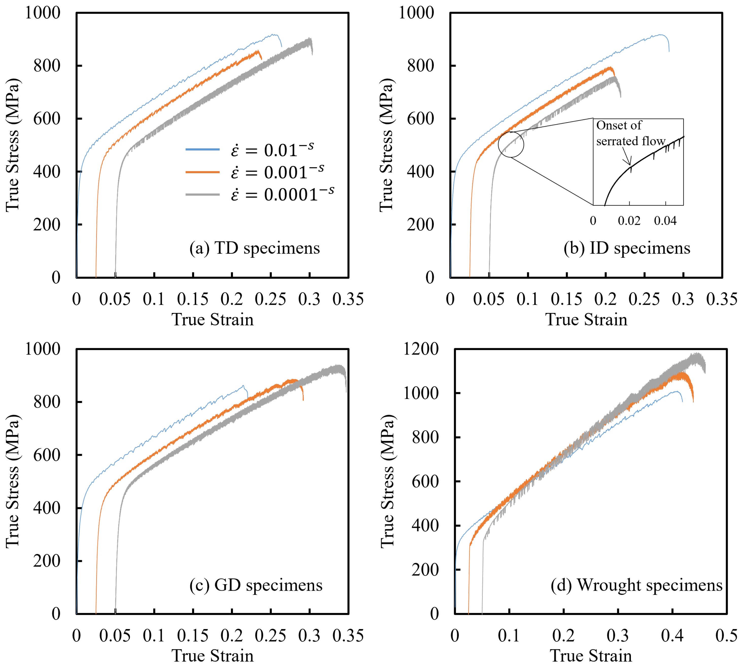
The stress–strain curves of WAAM IN718 specimens taken along the TD, GD, and ID directions, as well as wrought IN718 specimens, are shown in Figure 3. Each test condition was repeated three times, but only one stress–strain curve for each condition is presented in the figure, with the error range of the three tests displayed in Table 2. The curves have been converted from engineering stress–strain to true stress–strain. It should be noted that, in order to clearly observe the stress–strain responses at different strain rates and avoid overlapping curves, the curves for strain rates of 10 3 s 1 and 10 4 s 1 in Figure 3 have been horizontally shifted to the right by 0.025 and 0.05, respectively.
In addition to the tensile curves depicted in Figure 3, the tensile experiments also provided the essential mechanical properties of WAAM IN718, including Young’s modulus, 0.2 % yield strength, ultimate tensile strength (UTS), and elongation, which are organized in Table 2. Furthermore, Table 2 presents the tensile test results for wrought IN718, allowing for a comparative analysis with the WAAM specimens.
As shown in Table 2, the Young’s modulus of WAAM IN718 specimens is generally lower than that of the wrought state. Among the three different directions, the GD specimens exhibit relatively lower values. The 0.2 % yield strengths of WAAM IN718 are higher than those of wrought IN718 at corresponding strain rates. This is because the WAAM specimens did not undergo solution treatment, resulting in the presence of strengthening phases precipitated during the deposition process [49]. However, the wrought IN718 specimens tested in this study underwent solution treatment without subsequent aging treatment, resulting in the absence of any strengthening phases [50].
The negative strain rate sensitivity is observed in both wrought and WAAM IN718 (see Table 2), wherein the yield strength increases as the strain rate decreases. This phenomenon is a typical characteristic resulting from the dynamic strain aging (DSA) effect in solution-strengthened alloys [39]. In wrought IN718, this phenomenon is more pronounced, with a yield strength discrepancy of over 15 MPa observed across three strain rates. In WAAM IN718, although this trend is also present, the increase in yield strength with decreasing strain rate is slightly less than that observed in wrought IN718.
According to the results presented in Figure 3 and Table 2, it can be observed that the strain-hardening rate of WAAM IN718 remains consistent across different experimental conditions involving strain rates and directions. Conversely, for wrought IN718, a slight increase in the strain-hardening rate is evident at low strain rates. When comparing the elongation values under various experimental conditions, it is noted that the elongation of WAAM specimens in the ID direction exhibits a slightly lower magnitude compared to specimens oriented along the other two directions. Furthermore, overall elongation values for WAAM specimens are found to be lower than those achieved by wrought IN718 counterparts.
The microhardness measurements of the WAAM-fabricated specimens revealed that the TD orientation (the ID–GD plane) exhibited the highest hardness, with an average value of 251 HV. The ID orientation (the TD–GD plane) showed a slightly lower hardness, averaging 246 HV, while the GD orientation (TD–ID plane) presented a relatively lower hardness, with an average value of 239 HV.

4. Portevin–Le Chatelier Effect

The plastic region of the stress–strain curve in Figure 3 exhibits pronounced oscillations, a phenomenon known as the Portevin–Le Chatelier (PLC) effect. This phenomenon is generally attributed to the pinning and release of dislocations by diffusible solute atoms. The rate of these processes is influenced by factors such as solute activation energy, mobile dislocation density, and vacancy concentration [42,51,52]. Previous studies have categorized the PLC effect into three types—A, B, and C—based on the appearance of serrations. To quantitatively assess the characteristics of the PLC effect, this section investigates both the critical strain for the onset of serrated flow [43,53,54] and a statistical analysis of stress jumps [55,56].

4.1. Critical Strain of PLC Onset

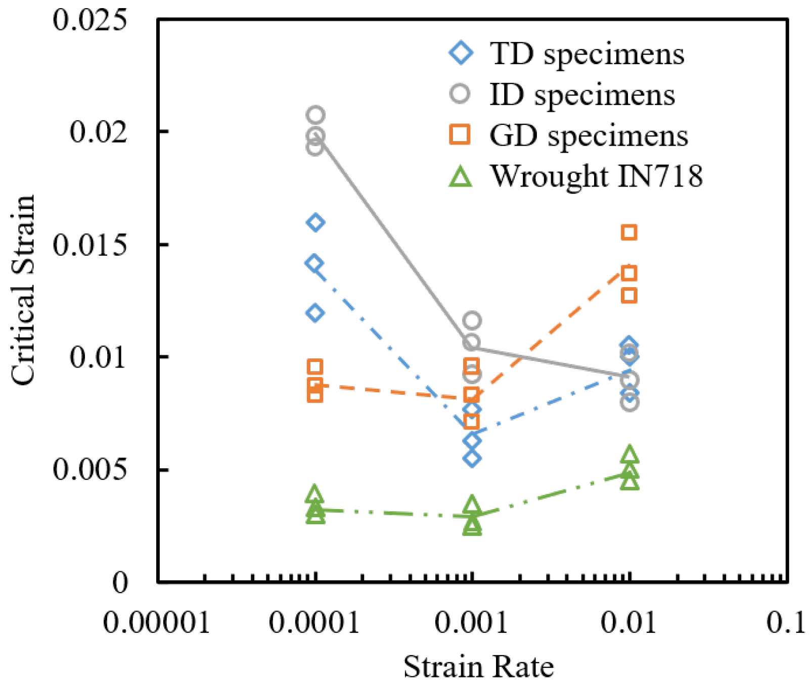
The critical strain for the onset of PLC, denoted as ε c , refers to the strain value at which the initial notable stress drop occurs in the tensile curve, as illustrated in the subgraph of Figure 3b. The critical strain values exhibited by each tensile test are summarized in Figure 4, with the curves fitted to show the relationship between the critical strain and the strain rate.
As depicted in Figure 4, the critical strain, ε c , of wrought IN718 is significantly lower than that of WAAM IN718. The critical strain value of the GD specimen at a strain rate of 10 3 s 1 is slightly lower than that at 10 4 s 1 . However, at 10 2 s 1 , the critical strain value significantly increases. This trend is consistent with the variation in critical strain values of wrought IN718 alloy with the strain rate observed in previous studies [57,58]. With an increasing strain rate, the critical strain value of the ID specimen shows a monotonically decreasing trend, while the critical strain value of the TD specimen initially decreases and then increases with an increasing strain rate.

4.2. Statistics of Stress Drops

The statistical analysis of the frequency and magnitude of serration amplitudes on the stress–strain curve is conducted [44,59]. The three types of Portevin–Le Chatelier (PLC) serrations exhibit distinct characteristics in terms of stress drop distributions, corresponding to different propagation behaviors of high strain rate bands during specimen deformation [55]. Type A serration is associated with continuously propagating bands, exhibiting a power-law behavior in the statistics of stress drops. Type B serration corresponds to the hopping propagation of localized high strain rate bands in a relay-race manner, and the corresponding distributions of stress drops exhibit a bell-shaped statistical feature. Type C serration is associated with randomly nucleated bands and corresponds to double-peaked distributions in stress drops [45,60].
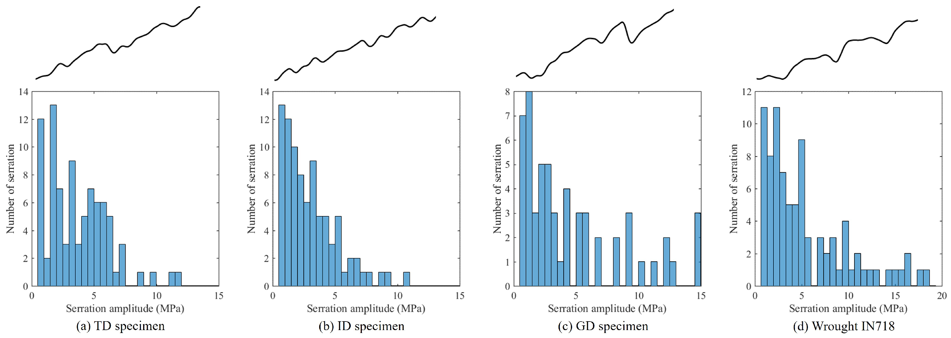
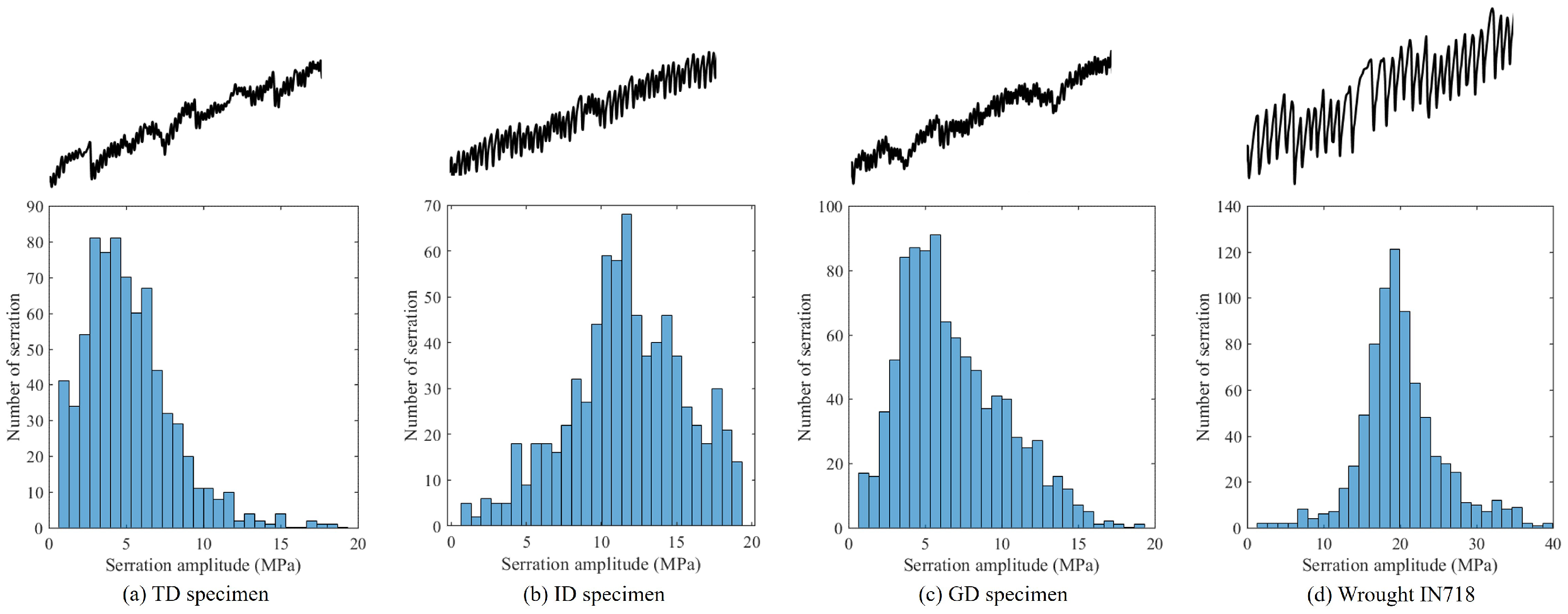
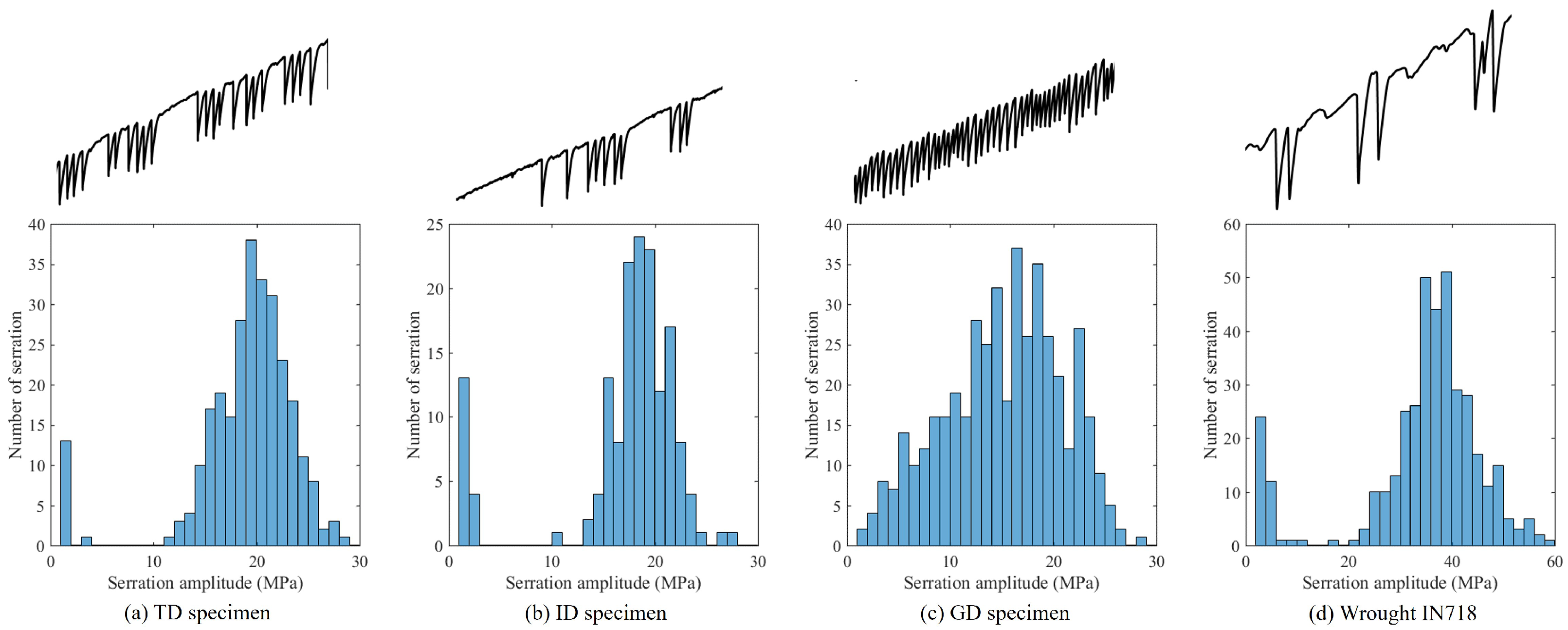
In this section, the statistical distribution of stress drops is analyzed for each stress–strain curve of WAAM and wrought IN718. Figure 5, Figure 6 and Figure 7 present the statistical results of the amplitude distribution of stress drops. The range of stress drops is divided into 30 equal intervals from zero to the maximum value. Each bar in the histogram represents the number of stress drops within a specific amplitude interval. To illustrate the different types of PLC instabilities, a segment of the stress–strain curve within the strain range of 0.08 to 0.1 is presented above each corresponding histogram. For each testing condition, three tensile specimens were examined, and the corresponding stress–strain curves exhibited consistent trends in stress-drop distribution. This ensures that the serration type classification is representative of the material behavior under each condition.
Figure 5 shows that both WAAM and wrought IN718 exhibit type A PLC behavior in tensile tests conducted at a strain rate of 10 2 s 1 and a temperature of 500 °C. This is evident from the height of the bars, which present an asymmetrical monotonically decreasing distribution in histograms. The strain–stress fragments for each histogram also indicate the type A character, where the strain corresponding to the ascending stage of each serration is longer than the descending stage.
The tensile tests implemented at a strain rate of 10 3 s 1 exhibit different PLC behaviors among the wrought and WAAM specimens in three directions, as shown in Figure 6. The stress oscillates evenly and densely around the mean height in ID WAAM and wrought IN718 specimens, indicating a type B PLC effect. However, for TD and GD WAAM specimens, the stress serrations show a mixed type A and B behavior, with high-frequency vibrations of relatively small amplitude occurring in the strain–stress curve between each two large stress drops. The histogram further confirms this conclusion, as the histogram corresponding to B-type PLC behavior exhibits a symmetrical bell-shaped distribution of stress drop. In the case of mixed type A and B, it manifests as a combination of the bell shape (B type) and a monotone decreasing pattern (A type), or can be described as a bell-shaped distribution with a symmetry axis shifted to the left.
When the strain rate decreased from 10 3 to 10 4 s 1 , significant differences in the types of PLC behavior were observed in the three-direction WAAM samples, as depicted in Figure 7. The serration of wrought, TD, and ID WAAM IN718 specimens exhibits a C-type characteristic, while the GD WAAM IN718 demonstrates a B-type characteristic. In terms of the histogram, the bar height of the C-type distribution showed two peaks: a narrow peak near the origin and a larger bell-shaped peak on the right. It is worth noting that for the GD specimen, although the B-type histogram did not form an ideal bell shape, it slightly shifted to the right. This suggests a tendency for PLC behavior to transition from a B type to a C type at this particular strain rate.
Based on the analysis of Figure 5, Figure 6 and Figure 7, it can be observed that as the strain rate decreases, all specimens exhibit a trend of transitioning from type A serrations to type B and then to type C serrations. However, at a strain rate of 10 3 s 1 , the transition of serration types in the TD and GD specimens exhibits a delayed transition compared to the ID and wrought IN718 specimens. When the strain rate further decreases to 10 4 s 1 , the serration type of the TD specimen becomes closer to that of the ID and wrought specimens, but the GD specimen still lags behind. Considering the trend of critical strain values with strain rate shown in Figure 4, it can be concluded that among the three WAAM-fabricated specimens, the GD specimen has the lowest critical strain value at low strain rates, while the ID specimen has the highest value. Typically, a lower critical strain value is associated with the occurrence of type B serration vibrations, while higher critical strain values are associated with type A or C serration vibrations [61,62]. Furthermore, when considering the author’s previous results from tensile testing of IN718 over a wider range of temperatures and strain rates [39], it can be concluded that the statistics of critical strain values and stress drop distributions yield the same conclusion. Specifically, for the strain rate required to exhibit the same PLC behavior, the GD specimen requires the lowest strain rate, the ID specimen requires a higher strain rate, and the TD specimen falls somewhere in between the two.

5. Discussion

5.1. Factors Influencing PLC Effect

From the experimental results described in the previous chapter, it can be observed that under the same strain rate, the PLC effect of IN718 alloy exhibits different behaviors when manufactured by WAAM and traditionally wrought methods. Specifically, the differences lie in the critical strain and the type of serrations. Based on previous research findings, factors that influence the PLC effect in the same alloy material include precipitates [63,64,65,66], solute atom concentration [67,68], grain size [69,70], and so on. In order to determine the influence of precipitates on the PLC effect, two additional tensile tests were conducted in this study. For these extra tensile tests, IN718 specimens fabricated by WAAM in the ID direction were selected, similar to the specimens used in the previous tensile tests. The temperature and strain rate for the tensile tests remained the same as before, at 500 °C and 10 3 s 1 , respectively. However, prior to the tensile experiments, two specimens underwent aging treatment for 30 and 120 min, respectively, at a temperature of 720 °C.
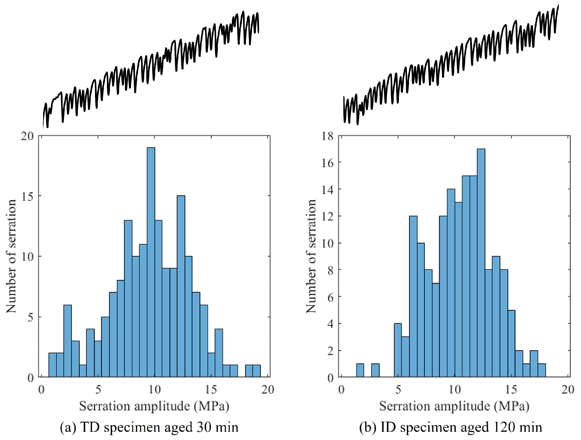
The results of these two additional tensile experiments were compared with the tensile tests performed on the unaged specimens, and the comparison is shown in Figure 8. It can be observed that the aging process led to an increase in the flow stress by approximately 200 MPa, with a stronger strengthening effect observed for longer aging times. This provides evidence for the precipitation of strengthening phases during the aging treatment, similar to that seen in the wrought IN718 aging treatment. When examining the critical strain values for the occurrence of the PLC effect, it was found that the critical strain values for the aged specimens were 0.0122 and 0.0138 for the 30 and 120 min aging treatments, respectively. These values are slightly higher than the critical strain value of the unaged specimens (approximately 0.011, as shown in Figure 4). Additionally, both aged and unaged specimens exhibited Type B PLC serrations at this temperature and strain rate, but there were subtle differences in the specific stress drop statistics, as shown in Figure 6b and Figure 9.
Previous studies have suggested that the primary diffusing solute atoms responsible for the PLC effect in IN718 alloy are carbon and chromium [67]. However, other studies have indicated that niobium and molybdenum are the main diffusing solute atoms causing the PLC effect in IN718 alloy [62], and the content of these two elements in WAAM alloy is slightly lower than that in wrought IN718 alloy [71]. By comparing the statistical analysis of stress drop amplitudes in the tensile curves before and after aging (Figure 6b and Figure 9), it can be observed that the most frequent stress drop amplitude decreased after aging, evidenced by a leftward shift in the peak of the histogram. In the context of the Type B PLC effect, a leftward shift in the peak value indicates that the occurrence of the PLC effect becomes more difficult, meaning that it requires a higher temperature or slower strain rate to produce the same PLC serrations as in the as-deposited state. During the aging process, Nb atoms in the matrix tend to cluster and form the γ phase, resulting in a decrease in the concentration of Nb atoms in the matrix. Therefore, it can be inferred that Nb atoms are one of the elements causing the PLC effect, and the differences in PLC behavior observed before and after aging are due to the decrease in Nb atom concentration. From the critical strain trends, this viewpoint is further supported: after 30 min and 120 min aging, the critical strain increased from 0.011 in the as-deposited state to 0.0122 and 0.0138, respectively, indicating that the PLC effect after aging, due to the reduced Nb content in the matrix, was more difficult to activate compared with the as-deposited condition.
Additionally, the WAAM IN718 produced using the process in this study has much larger grain sizes compared to wrought IN718. Evidence from previous studies [69,70] suggests that the critical strain value increases with increasing grain size due to its influence on the average velocity of moving dislocations, which is consistent with the findings in this paper (see Figure 4). The differences in the statistical analysis of stress drops in the different directional WAAM specimens shown in Figure 5, Figure 6 and Figure 7 might also be attributed to the anisotropy in grain morphology. As seen in Figure 7, at a strain rate of 10 4 s 1 , TD, ID, and wrought specimens all exhibit Type C serrations, while GD specimens remain in the Type B serration stage. However, the specific reasons for this still require further analysis at the crystal plasticity scale.

5.2. Fracture Morphology

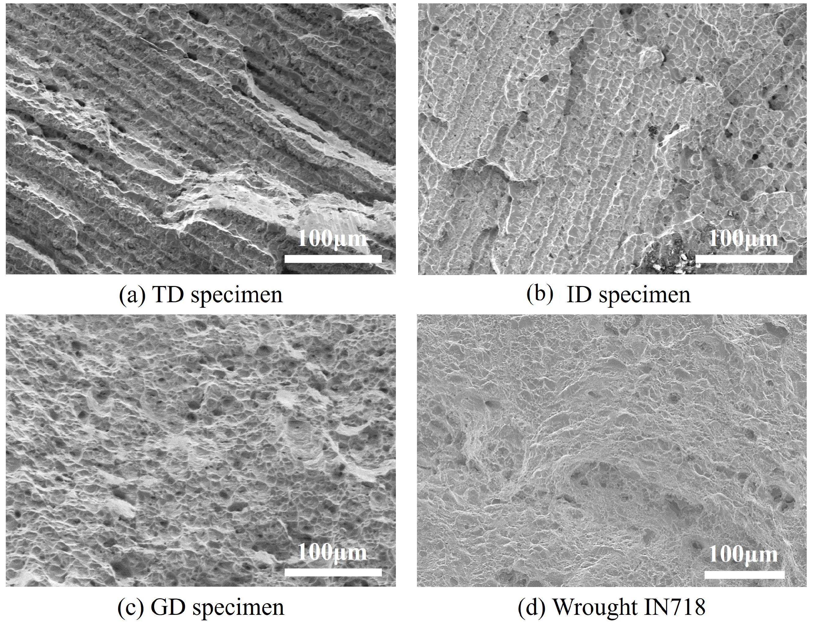
The fracture surfaces of the tensile test specimens were observed using SEM, as shown in Figure 10. The tensile tests were conducted on WAAM and wrought IN718 samples at a strain rate of 10 4 s 1 and a temperature of 500 °C. Two types of fracture surfaces were observed. The WAAM IN718 specimens extracted along the TD and ID directions exhibit a fibrous fracture surface, characterized by parallel and straight ravines resembling fibers with a width of approximately 15 μ m. Each ravine consists of shallow dimples (Figure 10a,b). In contrast, the fracture surfaces of the GD WAAM and wrought IN718 specimens exhibit a typical dimple fracture morphology. The fracture surface of the WAAM IN718 (see Figure 10c) shows relatively deeper and sparser dimples compared to the wrought IN718 (see Figure 10d). This difference in fracture morphology suggests a variation in the deformation mechanism and energy dissipation during fracture for the different directions and manufacturing processes of the IN718 alloy.
In this study, micro-CT scanning was performed on the WAAM-fabricated IN718 alloy using a scale computer tomography system. The model of the micro-CT equipment used was the Werth TomoScope L FQ. The minimum detectable pore diameter of the equipment was set to 4.5 μ m , but no pores were detected. Therefore, the influence of pore defects larger than this diameter on the fracture behavior was excluded. Consequently, the fibrous fracture surfaces observed in Figure 9a,b are highly likely to be caused by the anisotropy of the WAAM microstructure (see Figure 2). It is even possible that the anisotropy of the intragranular PLC behavior is influenced by the anisotropy of grain distribution [72]. This highlights the importance of employing lower-scale characterization or simulation methods to study the microscale mechanisms of PLC behavior within and between grains and its effect on the material’s failure mechanisms.
Furthermore, in the practical production of additively manufactured nickel-based superalloys, cracking during the printing process remains a challenge that cannot be completely eliminated. The complex thermal history and the accumulation of plastic deformation during WAAM are undoubtedly critical factors for understanding and mitigating such cracking issues. For nickel-based superalloys, elevated temperature and plastic deformation are often accompanied by the PLC effect investigated in this study. To the best of the authors’ knowledge, no published studies have explicitly linked process-induced cracking in additive manufacturing with the PLC effect [73,74]. Addressing this potential connection will require cross-scale experimental and numerical investigations, which constitutes a key focus of our future work.

6. Conclusions

In this study, IN718 specimens were fabricated using the WAAM technique, and mechanical testing was conducted on specimens in three different directions at a temperature of 500 °C. These results were compared with those obtained from conventionally wrought IN718, with an emphasis on the differences in PLC effects. The specific conclusions are as follows,
  • The EBSD characterization results revealed significant growth anisotropy in the WAAM-fabricated IN718 alloy, characterized by a columnar grain structure.
  • The yield strength of the WAAM-fabricated IN718 alloy consistently exceeded that of the wrought IN718 alloy, while the elastic modulus and elongation to failure were generally lower. Additionally, the WAAM-fabricated IN718 alloy exhibited negative strain rate sensitivity.
  • The critical strain values for the PLC effect in the WAAM-fabricated IN718 alloy were generally lower than those observed in wrought IN718 alloy. Furthermore, the critical strain values of the WAAM samples varied with strain rate in different directions.
  • As the strain rate decreases, both WAAM and deformed IN718 alloys exhibit a transition from type A to type B and then to type C PLC serrations. Considering the behavior of serration vibrations and the trend of critical strain values, the strain rate corresponding to the same PLC behavior is highest for the in-depth (ID) specimen, lowest for the growth direction (GD) specimen, and intermediate for the transverse direction (TD) specimen.

Author Contributions

Conceptualization, R.-H.S., D.-F.L. and L.Z.; methodology, R.-H.S. and X.Z.; software, R.-H.S. and Y.-J.Y.; validation, R.-H.S., Q.-W.Z. and X.Z.; formal analysis, X.Z., D.-F.L. and R.-P.S.; investigation, Y.-J.Y., Q.-W.Z. and H.-L.Q.; resources, L.Z. and H.-L.Q.; data curation, X.Z., Y.-J.Y. and Q.-W.Z.; writing—original draft preparation, R.-H.S.; writing—review and editing, L.Z., H.-L.Q., D.-F.L. and R.-P.S.; visualization, Q.-W.Z. and Y.-J.Y.; supervision, D.-F.L. and R.-P.S.; project administration, D.-F.L., L.Z. and R.-P.S.; funding acquisition, D.-F.L., H.-L.Q. and L.Z. All authors have read and agreed to the published version of the manuscript.

Funding

This work is supported by the Guangdong Basic and Applied Basic Research Foundation under Grant Number 2022A15150389. D.F. Li and R.P. Shi acknowledge financial support from the Shenzhen Science and Technology Program (Grant No. KJZD20240903102006009). In addition, R.P. Shi acknowledges financial support from the Shenzhen Science and Technology Program (Grant No. KJZD20240903101400001 and No. JCYJ20241202123504007).

Institutional Review Board Statement

Not applicable.

Informed Consent Statement

Not applicable.

Data Availability Statement

The data presented in this study are available on request from the corresponding author. The data are not publicly available due to confidentiality agreements with the industrial partner.

Conflicts of Interest

Author Hai-Long Qin was employed by the company Beijing GAONA Materials & Technology Co., Ltd. The remaining authors declare that the research was conducted in the absence of any commercial or financial relationships that could be construed as a potential conflict of interest.

References

  1. Mahobia, G.S.; Paulose, N.; Mannan, S.L.; Sudhakar, R.G.; Chattopadhyay, K.; Srinivas, N.S.; Singh, V. Effect of hot corrosion on low cycle fatigue behavior of superalloy IN718. Int. J. Fatigue 2014, 59, 272–281. [Google Scholar] [CrossRef]
  2. Zhang, S.H.; Zhang, H.Y.; Cheng, M. Tensile deformation and fracture characteristics of delta-processed Inconel 718 alloy at elevated temperature. Mater. Sci. Eng. A 2011, 528, 6253–6258. [Google Scholar] [CrossRef]
  3. Choudhury, I.A.; El-Baradie, M.A. Machinability of nickel-base super alloys: A general review. J. Mater. Process. Technol. 1998, 77, 278–284. [Google Scholar] [CrossRef]
  4. Song, R.H.; Qin, H.L.; Li, D.F.; Bi, Z.N.; Busso, E.P.; Yu, H.Y.; Liu, X.L.; Du, J.H.; Zhang, J. An Experimental and Numerical Study of Quenching-Induced Residual Stresses Under the Effect of Dynamic Strain Aging in an IN718 Superalloy Disc. J. Eng. Mater. Technol. 2022, 144, 011002. [Google Scholar] [CrossRef]
  5. Wong, K.V.; Hernandez, A. A review of additive manufacturing. Int. Sch. Res. Not. 2012, 2012, 208760. [Google Scholar] [CrossRef]
  6. Dye, D.; Hunziker, O.; Reed, R.C. Numerical analysis of the weldability of superalloys. Acta Mater. 2001, 49, 683–697. [Google Scholar] [CrossRef]
  7. Benz, M.G. Preparation of clean superalloys. Mater. Eng. 1999, 15, 31–48. [Google Scholar]
  8. Jinhui, D.; Xudong, L.; Qun, D.; Ying, L. Effect of solution treatment on the microstructure and mechanical properties of IN718 alloy. Rare Met. Mater. Eng. 2017, 46, 2359–2365. [Google Scholar] [CrossRef]
  9. Yuan, G.J.; Chen, H.; Li, D.F.; Gong, C.Y.; Zhang, X.C.; Tu, S.T. The effect of δ phase on the microplasticity evolution of a heat-treated nickel base superalloy. Mech. Mater. 2020, 148, 103520. [Google Scholar] [CrossRef]
  10. Zhang, F.; Cao, W.; Zhang, C.; Chen, S.; Zhu, J.; Lv, D. Simulation of Co-precipitation Kinetics of γ and γ′′ in Superalloy 718. In Proceedings of the 9th International Symposium on Superalloy 718 & Derivatives: Energy, Aerospace, and Industrial Applications, Pittsburgh, PA, USA, 3–6 June 2018; Springer: Cham, Switzerland, 2018; pp. 147–161. [Google Scholar]
  11. Qin, H.; Bi, Z.; Yu, H.; Feng, G.; Zhang, R.; Guo, X.; Chi, H.; Du, J.; Zhang, J. Assessment of the stress-oriented precipitation hardening designed by interior residual stress during ageing in IN718 superalloy. Mater. Sci. Eng. A 2018, 728, 183–195. [Google Scholar] [CrossRef]
  12. Jia, Q.; Gu, D. Selective laser melting additive manufacturing of Inconel 718 superalloy parts: Densification, microstructure and properties. J. Alloys Compd. 2014, 585, 713–721. [Google Scholar] [CrossRef]
  13. Raghavan, N.; Dehoff, R.; Pannala, S.; Simunovic, S.; Kirka, M.; Turner, J.; Carlson, N.; Babu, S.S. Numerical modeling of heat-transfer and the influence of process parameters on tailoring the grain morphology of IN718 in electron beam additive manufacturing. Acta Mater. 2016, 112, 303–314. [Google Scholar] [CrossRef]
  14. Wang, Z.; Guan, K.; Gao, M.; Li, X.; Chen, X.; Zeng, X. The microstructure and mechanical properties of deposited-IN718 by selective laser melting. J. Alloys Compd. 2012, 513, 518–523. [Google Scholar] [CrossRef]
  15. Dhinakaran, V.; Ajith, J.; Fahmidha, A.F.Y.; Jagadeesha, T.; Sathish, T.; Stalin, B. Wire Arc Additive Manufacturing (WAAM) process of nickel based superalloys—A review. Mater. Today Proc. 2020, 21, 920–925. [Google Scholar] [CrossRef]
  16. Rodrigues, T.A.; Duarte, V.; Miranda, R.M.; Santos, T.G.; Oliveira, J.P. Current status and perspectives on wire and arc additive manufacturing (WAAM). Materials 2019, 12, 1121. [Google Scholar] [CrossRef]
  17. Wu, B.; Pan, Z.; Ding, D.; Cuiuri, D.; Li, H.; Xu, J.; Norrish, J. A review of the wire arc additive manufacturing of metals: Properties, defects and quality improvement. J. Manuf. Process. 2018, 35, 127–139. [Google Scholar] [CrossRef]
  18. Williams, S.W.; Martina, F.; Addison, A.C.; Ding, J.; Pardal, G.; Colegrove, P. Wire + arc additive manufacturing. Mater. Sci. Technol. 2016, 32, 641–647. [Google Scholar] [CrossRef]
  19. Xu, X.; Ganguly, S.; Ding, J.; Seow, C.E.; Williams, S. Enhancing mechanical properties of wire+ arc additively manufactured INCONEL 718 superalloy through in-process thermomechanical processing. Mater. Des. 2018, 160, 1042–1051. [Google Scholar] [CrossRef]
  20. Ding, D.; Pan, Z.; Cuiuri, D.; Li, H. Wire-feed additive manufacturing of metal components: Technologies, developments and future interests. Int. J. Adv. Manuf. Technol. 2015, 81, 465–481. [Google Scholar] [CrossRef]
  21. Srivastava, S.; Garg, R.K.; Sharma, V.S.; Sachdeva, A. Measurement and Mitigation of Residual Stress in Wire-Arc Additive Manufacturing: A Review of Macro-Scale Continuum Modelling Approach. Arch. Comput. Methods Eng. 2020, 28, 1–25. [Google Scholar] [CrossRef]
  22. Lan, B.; Wang, Y.; Liu, Y.; Hooper, P.; Hopper, C.; Zhang, G.; Zhang, X.; Jiang, J. The influence of microstructural anisotropy on the hot deformation of wire arc additive manufactured (WAAM) Inconel 718. Mater. Sci. Eng. A 2021, 823, 141733. [Google Scholar] [CrossRef]
  23. Xu, X.; Ding, J.; Ganguly, S.; Williams, S. Investigation of process factors affecting mechanical properties of INCONEL 718 superalloy in wire+ arc additive manufacture process. J. Mater. Process. Technol. 2019, 265, 201–209. [Google Scholar] [CrossRef]
  24. Bhujangrao, T.; Veiga, F.; Suárez, A.; Iriondo, E.; Mata, F.G. High-Temperature Mechanical Properties of IN718 Alloy: Comparison of Additive Manufactured and Wrought Samples. Crystals 2020, 10, 689. [Google Scholar] [CrossRef]
  25. Chen, Z.; Soh, G.S. Microstructure and mechanical properties of Wire Arc Additive Manufactured (WAAM) Inconel 718 parts via post heat treatments. Mater. Today Proc. 2022, 70, 567–573. [Google Scholar] [CrossRef]
  26. Seow, C.E.; Coules, H.E.; Wu, G.; Khan, R.H.; Xu, X.; Williams, S. Wire+ Arc Additively Manufactured Inconel 718: Effect of post-deposition heat treatments on microstructure and tensile properties. Mater. Des. 2019, 183, 108157. [Google Scholar] [CrossRef]
  27. Kindermann, R.M.; Roy, M.J.; Morana, R.; Francis, J.A. Effects of microstructural heterogeneity and structural defects on the mechanical behaviour of wire+ arc additively manufactured Inconel 718 components. Mater. Sci. Eng. A 2022, 839, 142826. [Google Scholar] [CrossRef]
  28. Alonso, U.; Veiga, F.; Suárez, A.; Del Val, A.G. Characterization of Inconel 718 superalloy fabricated by wire Arc Additive Manufacturing: Effect on mechanical properties and machinability. J. Mater. Res. Technol. 2021, 14, 2665–2676. [Google Scholar] [CrossRef]
  29. Sun, L.; Jiang, F.; Huang, R.; Yuan, D.; Guo, C.; Wang, J. Anisotropic mechanical properties and deformation behavior of low-carbon high-strength steel component fabricated by wire and arc additive manufacturing. Mater. Sci. Eng. A 2020, 787, 139514. [Google Scholar] [CrossRef]
  30. Hassel, T.; Carstensen, T. Properties and anisotropy behaviour of a nickel base alloy material produced by robot-based wire and arc additive manufacturing. Weld. World 2020, 64, 1921–1931. [Google Scholar] [CrossRef]
  31. Arrazola, P.J.; Kortabarria, A.; Madariaga, A.; Esnaola, J.A.; Fernandez, E.; Cappellini, C.; Ulutan, D.; Özel, T. On the machining induced residual stresses in IN718 nickel-based alloy: Experiments and predictions with finite element simulation. Simul. Model. Pract. Theory 2014, 41, 87–103. [Google Scholar] [CrossRef]
  32. Hönnige, J.; Seow, C.E.; Ganguly, S.; Xu, X.; Cabeza, S.; Coules, H.; Williams, S. Study of residual stress and microstructural evolution in as-deposited and inter-pass rolled Wire plus Arc Additively Manufactured Inconel 718 alloy after ageing treatment. Mater. Sci. Eng. A 2020, 801, 140368. [Google Scholar] [CrossRef]
  33. Shen, C.; Reid, M.; Liss, K.D.; Pan, Z.; Ma, Y.; Cuiuri, D.; Van Duin, S.; Li, H. Neutron diffraction residual stress determinations in Fe3Al based iron aluminide components fabricated using wire-arc additive manufacturing (WAAM). Addit. Manuf. 2019, 29, 100774. [Google Scholar] [CrossRef]
  34. Wang, Z.; Denlinger, E.; Michaleris, P.; Stoica, A.D.; Ma, D.; Beese, A.M. Residual stress mapping in Inconel 625 fabricated through additive manufacturing: Method for neutron diffraction measurements to validate thermomechanical model predictions. Mater. Des. 2017, 113, 169–177. [Google Scholar] [CrossRef]
  35. Vikram, R.J.; Singh, A.; Suwas, S. Effect of heat treatment on the modification of microstructure of selective laser melted (SLM) IN718 and its consequences on mechanical behavior. J. Mater. Res. 2020, 35, 1949–1962. [Google Scholar] [CrossRef]
  36. Zhao, J.R.; Hung, F.Y.; Lui, T.S. Microstructure and tensile fracture behavior of three-stage heat treated inconel 718 alloy produced via laser powder bed fusion process. J. Mater. Res. Technol. 2020, 9, 3357–3367. [Google Scholar] [CrossRef]
  37. Sui, S.; Tan, H.; Chen, J.; Zhong, C.; Li, Z.; Fan, W.; Gasser, A.; Huang, W. The influence of Laves phases on the room temperature tensile properties of Inconel 718 fabricated by powder feeding laser additive manufacturing. Acta Mater. 2019, 164, 413–427. [Google Scholar] [CrossRef]
  38. Xi, N.; Fang, X.; Duan, Y.; Zhang, Q.; Huang, K. Wire arc additive manufacturing of Inconel 718: Constitutive modelling and its microstructure basis. J. Manuf. Process. 2022, 75, 1134–1143. [Google Scholar] [CrossRef]
  39. Song, R.H.; Qin, H.L.; Bi, Z.N.; Zhang, J.; Chi, H.; Busso, E.P.; Li, D.F. Experimental and numerical investigations of dynamic strain ageing behaviour in solid solution treated Inconel 718 superalloy. Eng. Comput. 2020, 38, 19–35. [Google Scholar] [CrossRef]
  40. Ren, S.C.; Morgeneyer, T.F.; Mazière, M.; Forest, S.; Rousselier, G. Effect of Lüders and Portevin-Le Chatelier localization bands on plasticity and fracture of notched steel specimens studied by DIC and FE simulations. Int. J. Plast. 2020, 136, 102880. [Google Scholar] [CrossRef]
  41. Marais, A.; Maziére, M.; Forest, S.; Parrot, A.; Le Delliou, P. Identification of a strain-aging model accounting for Lüders behavior in a C-Mn steel. Philos. Mag. 2012, 92, 3589–3617. [Google Scholar] [CrossRef]
  42. McCormigk, P.G. A model for the Portevin-Le Chatelier effect in substitutional alloys. Acta Metall. 1972, 20, 351–354. [Google Scholar] [CrossRef]
  43. Chihab, K.; Fressengeas, C. Time distribution of stress drops, critical strain and crossover in the dynamics of jerky flow. Mater. Sci. Eng. A 2003, 356, 102–107. [Google Scholar] [CrossRef]
  44. Lebyodkin, M.; Dunin-Barkowskii, L.; Brechet, Y.; Estrin, Y.; Kubin, L.P. Spatio-temporal dynamics of the Portevin–Le Chatelier effect: Experiment and modelling. Acta Mater. 2000, 48, 2529–2541. [Google Scholar] [CrossRef]
  45. Lebedkina, T.A.; Lebyodkin, M.A. Effect of deformation geometry on the intermittent plastic flow associated with the Portevin–Le Chatelier effect. Acta Mater. 2008, 56, 5567–5574. [Google Scholar] [CrossRef]
  46. Cheng, X.M.; Morris, J.G. The anisotropy of the portevin-le chatelier effect in aluminum alloys. Scr. Mater. 2000, 43, 651–658. [Google Scholar] [CrossRef]
  47. Mizera, J.; Kurzydlowski, K.J. On the anisotropy of the Portevin–Le Chatelier plastic instabilities in Al–Li–Cu–Zr alloy. Scr. Mater. 2001, 45, 801–806. [Google Scholar] [CrossRef]
  48. Cruzado, A.; Lucarini, S.; LLorca, J.; Segurado, J. Crystal plasticity simulation of the effect of grain size on the fatigue behavior of polycrystalline Inconel 718. Int. J. Fatigue 2018, 113, 236–245. [Google Scholar] [CrossRef]
  49. Laskowski, R.; Wang, K.; Ahluwalia, R.; Bai, K.; Vastola, G.; Zhang, Y.W. Phase field model for multiphase alloys under arbitrary thermal history: An application to IN718 super-alloy. J. Alloys Compd. 2021, 861, 158630. [Google Scholar] [CrossRef]
  50. Sundararaman, M.; Mukhopadhyay, P.; Banerjee, S. Some aspects of the precipitation of metastable intermetallic phases in Inconel 718. Metall. Trans. A 1992, 23, 2015–2028. [Google Scholar] [CrossRef]
  51. Venkadesan, S.; Phaniraj, C.; Sivaprasad, P.V.; Rodriguez, P. Activation energy for serrated flow in a 15Cr-5Ni Ti-modified austenitic stainless steel. Acta Metall. Mater. 1992, 40, 569–580. [Google Scholar] [CrossRef]
  52. Zhou, H.; Fang, J.; Chen, Y.; Yang, L.; Zhang, H.; Lu, Y.; He, Y. Internal friction studies on dynamic strain aging in P91 ferritic steel. Mater. Sci. Eng. A 2016, 676, 361–365. [Google Scholar] [CrossRef]
  53. Fu, S.; Cheng, T.; Zhang, Q.; Hu, Q.; Cao, P. Two mechanisms for the normal and inverse behaviors of the critical strain for the Portevin–Le Chatelier effect. Acta Mater. 2012, 60, 6650–6656. [Google Scholar] [CrossRef]
  54. Mazière, M.; Dierke, H. Investigations on the Portevin Le Chatelier critical strain in an aluminum alloy. Comput. Mater. Sci. 2012, 52, 68–72. [Google Scholar] [CrossRef]
  55. Lebyodkin, M.A.; Estrin, Y. Multifractal analysis of the Portevin–Le Chatelier effect: General approach and application to AlMg and AlMg/Al2O3 alloys. Acta Mater. 2005, 53, 3403–3413. [Google Scholar] [CrossRef]
  56. Maj, P.; Zdunek, J.; Gizynski, M.; Mizera, J.; Kurzydlowski, K.J. Statistical analysis of the Portevin–Le Chatelier effect in Inconel 718 at high temperature. Mater. Sci. Eng. A 2014, 619, 158–164. [Google Scholar] [CrossRef]
  57. Hähner, P. On the critical conditions of the Portevin-Le Chatelier effect. Acta Mater. 1997, 45, 3695–3707. [Google Scholar] [CrossRef]
  58. Abbadi, M.; Hähner, P.; Zeghloul, A. On the characteristics of Portevin–Le Chatelier bands in aluminum alloy 5182 under stress-controlled and strain-controlled tensile testing. Mater. Sci. Eng. A 2002, 337, 194–201. [Google Scholar] [CrossRef]
  59. Rodriguez, P.; Venkadesan, S. Serrated plastic flow revisited. In Solid State Phenomena; Trans Tech Publications Ltd.: Pfäffikon, Switzerland, 1995; Volume 42, pp. 257–266. [Google Scholar]
  60. Lebyodkin, M.A.; Lebedkina, T.A. Multifractality and randomness in the unstable plastic flow near the lower strain-rate boundary of instability. Phys. Rev. E 2008, 77, 026111. [Google Scholar] [CrossRef]
  61. Han, G.M.; Tian, C.G.; Chu, Z.K.; Cui, C.Y.; Hu, Z.Q.; Sun, X.F. Activation energy calculations for the Portevin–Le Chatelier effect in nimonic 263 superalloy. Metall. Mater. Trans. A 2015, 46, 4629–4635. [Google Scholar] [CrossRef]
  62. Max, B.; Viguier, B.; Andrieu, E.; Cloue, J.M. A re-examination of the Portevin-Le Chatelier effect in alloy 718 in connection with oxidation-assisted intergranular cracking. Metall. Mater. Trans. A 2014, 45, 5431–5441. [Google Scholar] [CrossRef]
  63. Rezende, M.C.; Araújo, L.S.; Gabriel, S.B.; Dille, J.; de Almeida, L.H. Observations on dynamic strain aging manifestation in inconel 718 superalloy. In Materials Science Forum; Trans Tech Publications Ltd.: Pfäffikon, Switzerland, 2018; Volume 930, pp. 390–394. [Google Scholar]
  64. Chen, J.Z.; Liang, Z.H.E.N.; Fan, L.W.; Yang, S.J.; Dai, S.L.; Shao, W.Z. Portevin-Le Chatelier effect in Al-Zn-Mg-Cu-Zr aluminum alloy. Trans. Nonferrous Met. Soc. China 2009, 19, 1071–1075. [Google Scholar] [CrossRef]
  65. Chen, W.; Chaturvedi, M.C. On the mechanism of serrated deformation in aged Inconel 718. Mater. Sci. Eng. A 1997, 229, 163–168. [Google Scholar] [CrossRef]
  66. Thevenet, D.; Mliha-Touati, M.; Zeghloul, A. The effect of precipitation on the Portevin-Le Chatelier effect in an Al–Zn–Mg–Cu alloy. Mater. Sci. Eng. A 1999, 266, 175–182. [Google Scholar] [CrossRef]
  67. Hale, C.L.; Rollings, W.S.; Weaver, M.L. Activation energy calculations for discontinuous yielding in Inconel 718SPF. Mater. Sci. Eng. A 2001, 300, 153–164. [Google Scholar] [CrossRef]
  68. Jiang, H.; Zhang, Q.; Wu, X.; Fan, J. Spatiotemporal aspects of the Portevin–Le Chatelier effect in annealed and solution-treated aluminum alloys. Scr. Mater. 2006, 54, 2041–2045. [Google Scholar] [CrossRef]
  69. Charnock, W. The influence of grain size on the nature of portevin-lechatelier yielding. Philos. Mag. J. Theor. Exp. Appl. Phys. 1968, 18, 89–99. [Google Scholar] [CrossRef]
  70. Rodriguez, P. Serrated plastic flow. Bull. Mater. Sci. 1984, 6, 653–663. [Google Scholar] [CrossRef]
  71. Brechet, Y.; Estrin, Y. On the influence of precipitation on the Portevin-Le Chatelier effect. Acta Metall. Mater. 1995, 43, 955–963. [Google Scholar] [CrossRef]
  72. Chen, J.; Madi, Y.; Morgeneyer, T.F.; Besson, J. Plastic flow and ductile rupture of a 2198 Al–Cu–Li aluminum alloy. Comput. Mater. Sci. 2011, 50, 1365–1371. [Google Scholar] [CrossRef]
  73. Pink, E.; Król, J. Precipitation and serrated flow in AlZn10. Acta Metall. Mater. 1995, 43, 2351–2357. [Google Scholar] [CrossRef]
  74. Zhu, K.Y.; Dai, S.; Zou, S.H.; Yu, Y.J.; Deng, Z.C. Experimental study and crystal plasticity modeling of additive manufacturing IN718 superalloy considering negative strain rate sensitivity behavior. Eur. J. Mech. A Solids 2024, 106, 105304. [Google Scholar] [CrossRef]
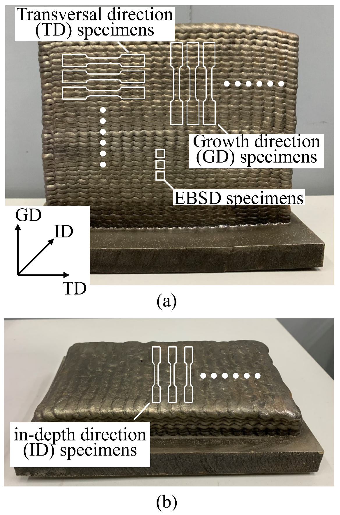
Figure 1. The diagram of two WAAM IN718 blocks built in (a) transversal–growth direction (TD-GD) and (b) transversal–in-depth direction (TD-ID), and the location where the specimens were extracted from the blocks.
Metals 15 00949 g001
Figure 2. EBSD orientation maps of the WAAM IN718 for TD-ID, ID-GD, and TD-GD planes.
Metals 15 00949 g002
Figure 3. Experimental stress–strain curves of WAAM IN718 specimens extracted along (a) TD, (b) ID, and (c) GD, and of (d) wrought IN718, testing at 500 °C.
Metals 15 00949 g003
Figure 4. The critical strain of PLC effect as a function of the strain rate for WAAM and wrought IN718.
Metals 15 00949 g004
Figure 5. The distribution histograms of stress drop amplitude for the strain–stress curve and the corresponding curve fragment, for WAAM IN718 specimens extracted along (a) TD, (b) ID, (c) GD, and (d) wrought IN718 specimens at 500 °C and 10 2 s 1 .
Metals 15 00949 g005
Figure 6. The distribution histograms of stress drop amplitude for the strain–stress curve and the corresponding curve fragment, testing for WAAM IN718 specimens extracted along (a) TD, (b) ID, (c) GD, and (d) wrought IN718 specimens at 500 °C and 10 3 s 1 .
Metals 15 00949 g006
Figure 7. The distribution histograms of stress drop amplitude for the strain–stress curve and the corresponding curve fragment, testing for WAAM IN718 specimens extracted along (a) TD, (b) ID, (c) GD, and (d) wrought IN718 specimens at 500 °C and 10 4 s 1 .
Metals 15 00949 g007
Figure 8. Comparison of experimental stress–strain curves between as-deposited and aging-treated WAAM specimens extracted along ID testing at 500 °C and 10 3 s 1 .
Metals 15 00949 g008
Figure 9. The distribution histograms of stress drop amplitude for the strain–stress curve and the corresponding curve fragment, testing at 500 °C and 10 4 s 1 for WAAM IN718 specimens aged (a) 30 min, (b) 120 min.
Metals 15 00949 g009
Figure 10. SEM images of fracture surfaces from tested WAAM specimen extracted along (a) TD, (b) ID, and (c) GD, and (d) wrought IN718, testing at 500 °C and 10 4 s 1 .
Metals 15 00949 g010
Table 1. Chemical composition of WAAM and wrought IN718 (wt%).
NiCrFeNbMoTiAlC
WAAM IN718 wireBalance18.5617.805.012.870.970.600.04
Wrought IN718Balance18.0518.005.422.900.910.480.023
Table 2. Mechanical properties obtained by tensile tests of WAAM and wrought IN718.
WAAM IN718Wrought IN718
Strain Rate ( s 1 ) 10 2 10 3 10 4 10 2 10 3 10 4
Young’s Modulus (GPa)TD 152 ± 5 162 ± 6 145 ± 18 174 ± 1 167 ± 4 163 ± 1
ID 159 ± 7 161 ± 17 142 ± 1
GD 131 ± 6 142 ± 10 137 ± 5
Yield Strength (MPa)TD 359 ± 12 370 ± 9 367 ± 1 282 ± 5 308 ± 18 335 ± 6
ID 350 ± 6 357 ± 0 359 ± 3
GD 340 ± 5 344 ± 6 352 ± 1
UTS (MPa)TD 707 ± 7 694 ± 3 695 ± 11 675 ± 7 755 ± 20 823 ± 14
ID 667 ± 19 637 ± 27 633 ± 13
GD 683 ± 12 695 ± 4 706 ± 2
Elongation (%)TD 32 ± 2 22 ± 2 32 ± 3 52 ± 1 50 ± 1 50 ± 1
ID 25 ± 4 18 ± 6 17 ± 3
GD 26 ± 3 34 ± 3 37 ± 2
Disclaimer/Publisher’s Note: The statements, opinions and data contained in all publications are solely those of the individual author(s) and contributor(s) and not of MDPI and/or the editor(s). MDPI and/or the editor(s) disclaim responsibility for any injury to people or property resulting from any ideas, methods, instructions or products referred to in the content.