Article

The Effect of Welding Parameters on the Morphology and Mechanical Properties of AA6061-T6/CF-PPS Friction Stir Lap Welding Joints

1
School of Energy and Mechanical Engineering, Shanghai University of Electric Power, Shanghai 201306, China
2
Aerospace Engineering Equipment (Suzhou) Co., Ltd., Suzhou 215104, China
3
School of Mechanical and Electrical Engineering, Soochow University, Suzhou 215000, China
4
School of Mechanical Engineering, Shandong University of Technology, Zibo 255000, China
5
Shanghai Key Laboratory of Digital Manufacture for Thin-Walled Structures, Shanghai Jiao Tong University, Shanghai 200240, China
*
Author to whom correspondence should be addressed.
Metals 2025, 15(9), 1049; https://doi.org/10.3390/met15091049
Submission received: 21 August 2025 / Revised: 11 September 2025 / Accepted: 16 September 2025 / Published: 20 September 2025
(This article belongs to the Special Issue New Welding Materials and Green Joint Technology—2nd Edition)

Abstract

The application of lightweight materials in the automotive industry can effectively achieve further weight reduction while maintaining overall structural strength, thereby reducing energy consumption. Currently, friction stir spot welding (FSSW) is the primary method for joining carbon fiber-reinforced polyphenylene sulfide (CF-PPS) with aluminum alloys. This study successfully achieved the connection between 6061-T6 aluminum alloy and CF-PPS using the more operationally convenient friction stir lap welding (FSLW) technique. The primary objective of this study was to explore the potential of expanding the welding technologies available for successfully joining these two dissimilar materials. The joint morphology and strength were analyzed through metallographic observation and tensile testing, and the effects of different welding parameters on the microstructure and mechanical properties of dissimilar joints were studied. The study demonstrated that the successful connection between AA6061-T6 and CF-PPS was primarily attributable to the combined effects of mechanical interlocking and mixture bonding. The joint strength demonstrated a maximum value of 9.41 MPa when the following parameters were set: a rotation speed of 1800 rpm, a welding speed of 40 mm/min, and a plunge depth of 0.2 mm. Although low rotation speed and low welding speed cannot form an effective mechanical interlocking structure for the joint, the failed joints have different causes. When the rotation and welding speeds are fixed, changing the plunge depth cannot change the interlocking structure of the joint. A larger plunge depth will thin the weld and greatly reduce the joint strength.

1. Introduction

In order to address the escalating energy consumption and carbon emissions, the automotive industry is poised to adopt a multifaceted approach, including the measures to conserve energy and reduce emissions, as well as the adoption of lightweight design principles [1,2]. At present, the field of lightweight automotive design is chiefly advanced through three principal aspects: materials, structure, and process. Among these materials, aluminum alloy and carbon fiber-reinforced composites (CFRP) are notable for their low density and high strength, making them well-suited for use in automobile body structures [3,4,5,6]. Therefore, the key to achieving automotive lightweighting is to leverage the ideal properties of these lightweight materials to design and manufacture effective lightweight metal/CFRP hybrid structures.
A. Pramanik et al. [7]. point out that for the connection of dissimilar materials such as aluminum and CFRP, traditional mechanical fastening and adhesive bonding can be used to secure the two materials together in a relatively simple structure. However, the use of mechanical fasteners leads to stress concentration and weight loss; adhesive bonding requires complex surface treatment and a longer bonding curing time. Friction stir welding (FSW), as a new solid-state joining technology, can easily achieve the connection of aluminum and CFRP dissimilar materials due to its lower peak temperature and smaller welding pressure [8,9,10].
Carbon fiber-reinforced polyphenylene sulfide (CF-PPS) exhibits high strength and heat resistance. In pursuit of a lightweight design, the G650 business jet from Gulfstream utilizes lightweight carbon-fiber-reinforced plastic (CFRP) composite materials for its tail section, resulting in a 10% reduction in structural weight and a 20% reduction in costs [11]. In comparison with polyetheretherketone (PEEK), it offers distinct advantages, including reduced cost and simplified molding processes [12]. However, the PPS matrix itself is relatively fragile [13], so the selection of an appropriate welding method is paramount to the success of connecting dissimilar materials. In a related study, Andre et al. [14] successfully joined AA7075-T6 and CF-PPS using friction stir spot welding (FSSW). The FSSW employs the connecting force generated by the downward pressure of the stirring tool to deform the aluminum plate and CFRP, thereby forming a mechanically interlocked structure with upper and lower interlocking. This method has been demonstrated to effectively bind dissimilar materials. However, a small exit hole was left on the surface after welding, which had a deleterious effect on the integrity of the weld. H. Schäfer et al. [15] employed refill friction stir spot welding (RFSSW) to refill the cavity left by the moving shaft shoulder welding, thereby obtaining a defect-free joint and further improving the mechanical properties. Li et al. [16]. investigated the effect of rotational speed on the bonding quality of AA6061/CF-PPS dissimilar RFSSW joints. The presence of a wavy interface in the welded joint was observed, with varying rotational speeds resulting in different depths of metal embedding into the CF-PPS. This, in turn, caused differences in joint strength.
However, compared with general FSW, the RFSSW process is marginally more intricate, and the inherent limitations of spot welding in handling large structural components and the pronounced stress concentration issues remain unresolved. Presently, the FSSW technique is predominantly employed for the connection of aluminum alloys and CF-PPS, with limited research focusing on the direct FSW method. Sandeep et al. [17] investigated the effects of air and underwater welding environments on the friction stir lap welding (FSLW) process of dissimilar materials, specifically 7475 aluminum alloy and CF-PPS. A differential scanning calorimetry (DSC) analysis was conducted, which revealed a loss of crystallinity in polymers due to the application of FSLW technology. The welding environment exerts a substantial influence on the formation of voids within polymers, their tensile properties, and crystallinity loss.
Therefore, this study elected to utilize a lap joint with CF-PPS on the superior surface and aluminum alloy on the inferior surface to facilitate the welding of dissimilar materials. The process was further enhanced with respect to its viability in facilitating dissimilar joining between aluminum alloys and CF-PPS. The investigation encompassed the examination of the impact of rotation speed, welding speed, and plunge depth on the quality of the welding process. A comprehensive analysis of the morphology of the welding joint surface and cross-section was conducted to elucidate the underlying connection mechanism of friction stir welding between dissimilar metals and polymers.

2. Materials and Methods

This study selected aluminum alloy 6061-T6 (AA6061) and CF-PPS sheets with the same dimensions of 150 × 70 × 2 mm3. CF-PPS was produced using an injection molding process with a carbon fiber content of 30%. The carbon fibers were randomly distributed using this method, resulting in isotropic mechanical properties for the CFRP. The chemical composition and mechanical properties of AA6061-T6 are shown in Table 1 and Table 2, while the physical and mechanical properties of CF-PPS are presented in Table 3.
The testing equipment is the gantry-type 130 friction stir welding machine independently developed by Aerospace Engineering Equipment (Suzhou) Co., Ltd., Suzhou, China, with a structure as shown in Figure 1a. During welding, the welding position is first manually determined, a coordinate system is established, and the shoulder angle is set to 2°. Then, the machining program is input to conduct the welding test. The specific clamping configuration for welding is shown in Figure 1b. The test process uses a lap joint configuration with CF-PPS plate on top and 6061-T6 aluminum alloy below, secured using a combination of long pressure strips and pressure plates to fix the two plates in place.
Huang et al. [18] noted that using a three-fluted conical threaded stirring pin facilitates the formation of high-quality and surface-intact joint morphology. The stirring pin used for FSLW was made of H13 tool steel and had the following dimensions: shoulder diameter of 10 mm, pin bottom diameter of 4.4 mm, and height of 3 mm. To further enhance material flow during welding, concentric grooves were milled into the shoulder surface. Figure 2a shows an actual image of the pin, and Figure 2b shows the 3D design drawing. Derazkola et al. [19,20] studied the effect of the plunge depth and inclination angle of the pin on the quality of aluminum alloy and CFRP welded joints. Complete welded joints could be obtained when the plunge depth was in the range of 0.1–0.4 mm, and the performance changes were obvious. Therefore, based on this research, the tilt angle of the tool was set to 2°, and a single-factor experiment was conducted to study the effect of different welding parameters on quality. The experiment included rotation speeds ranging from 1600 to 2000 rpm, welding speeds ranging from 30 to 50 mm/min, and plunge depths ranging from 0.1 to 0.3 mm.
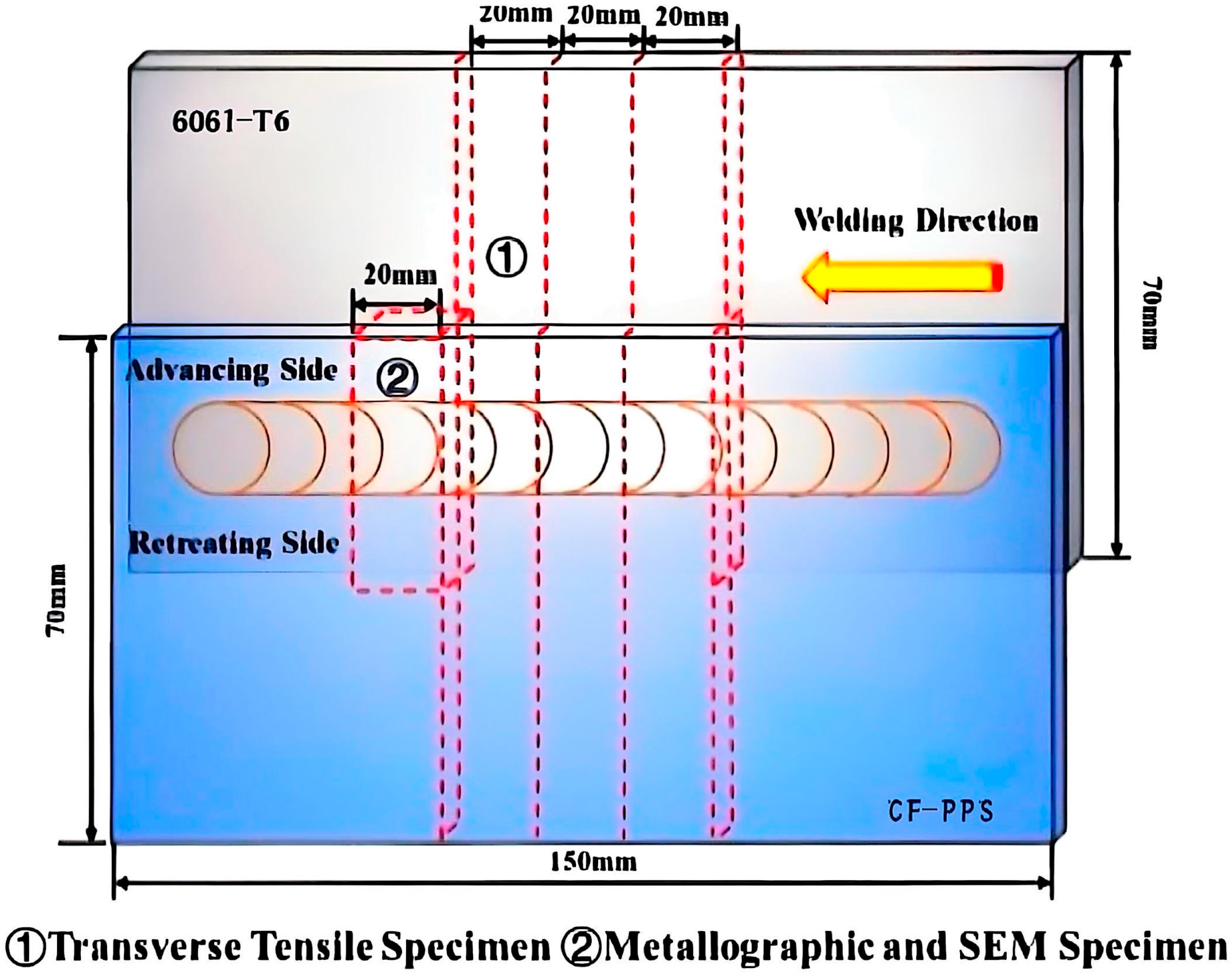
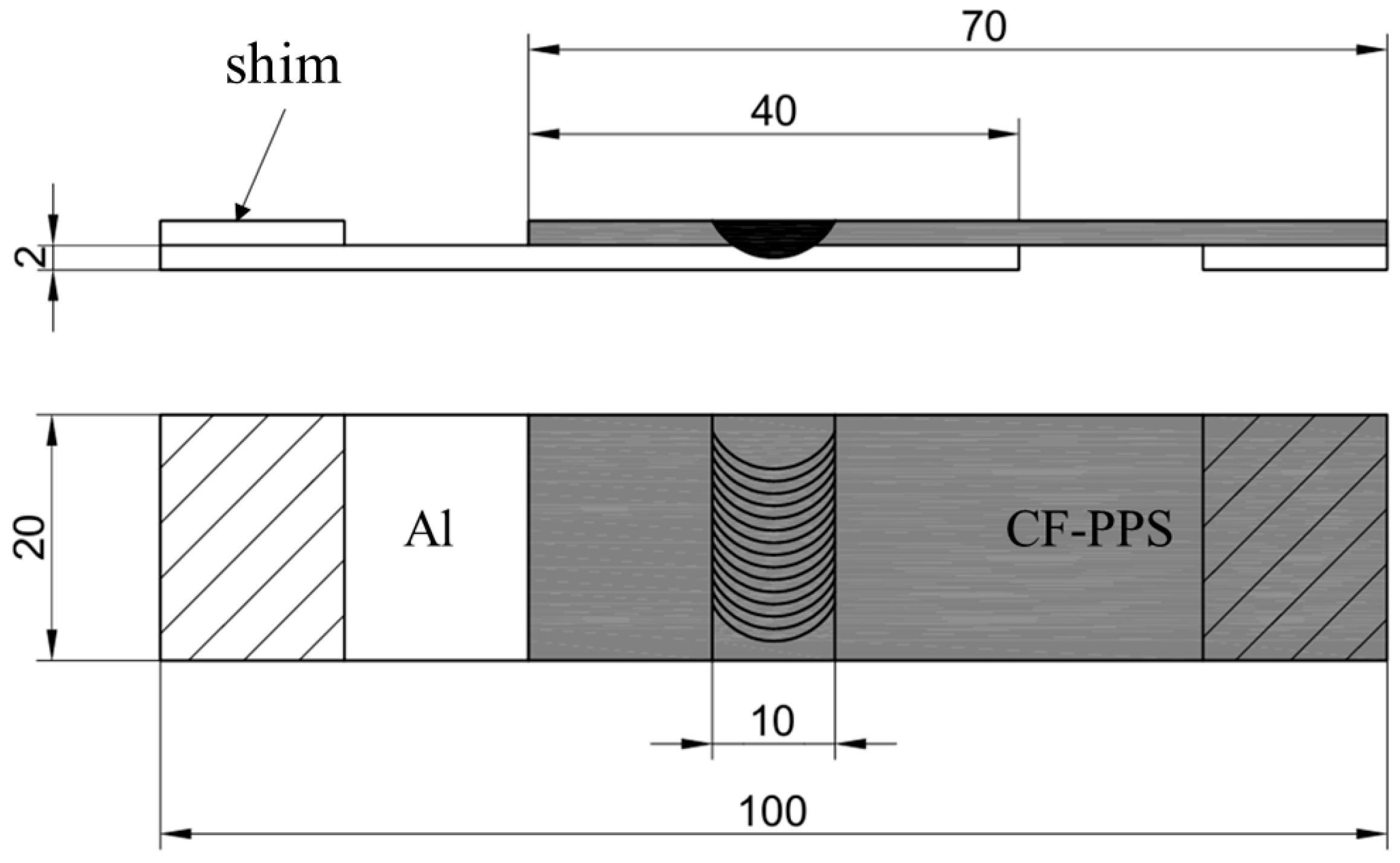
Before welding, the aluminum alloy surface must undergo a thorough sanding procedure using appropriate sandpaper, then clean it thoroughly with acetone and blow-dry it to ensure the removal of the aluminum oxide layer. For the CF-PPS, the surface should be wiped with an alcohol swab to remove dust and grease. Following the execution of the welding process, the appearance of the weld surface was examined using a stereomicroscope. To investigate the bonding mechanism between aluminum alloy and CF-PPS in the FSLW process, conventional metallographic techniques were used to prepare cross-sections of the joint. This approach was taken to facilitate observation of the microstructure at the interface. The mechanical properties of the joint were evaluated using lap shear tests. For each set of process parameters, four weld specimens were selected: one for metallographic examination and the remaining three for tensile strength testing. As illustrated in Figure 3, the lap joint configuration and specimen cutting locations are delineated. The specimens were then subjected to tensile-shear testing using the SUNS UTM5504X universal testing machine (Shenzhen Suns Technology Stock Co., Ltd., Shenzhen, China). The preparation of joint specimens was conducted in accordance with the provisions outlined in GB/T 7124-2008 [21] standards, as depicted in Figure 4. The loading rate was maintained at a constant rate of 1 mm/min. To eliminate additional torque generated during tensile loading, 2 mm shims were added at both ends of the specimens. In order to ensure measurement stability, three specimens were prepared from the longitudinal welds under each set of welding parameters. The average value of these specimens was taken as the joint shear load for that parameter.

3. Results and Discussion

A comprehensive review of the extant literature was conducted, and preliminary experiments were carried out, to analyze the effects of individual welding parameters (rotation speed, welding speed, and plunge depth) on dissimilar FSLW joints. The controlled variable method was employed to analyze the effects, and the results were documented. The process parameters are delineated in Table 4.

3.1. The Effect of Spindle Rotation Speed on Welding Quality

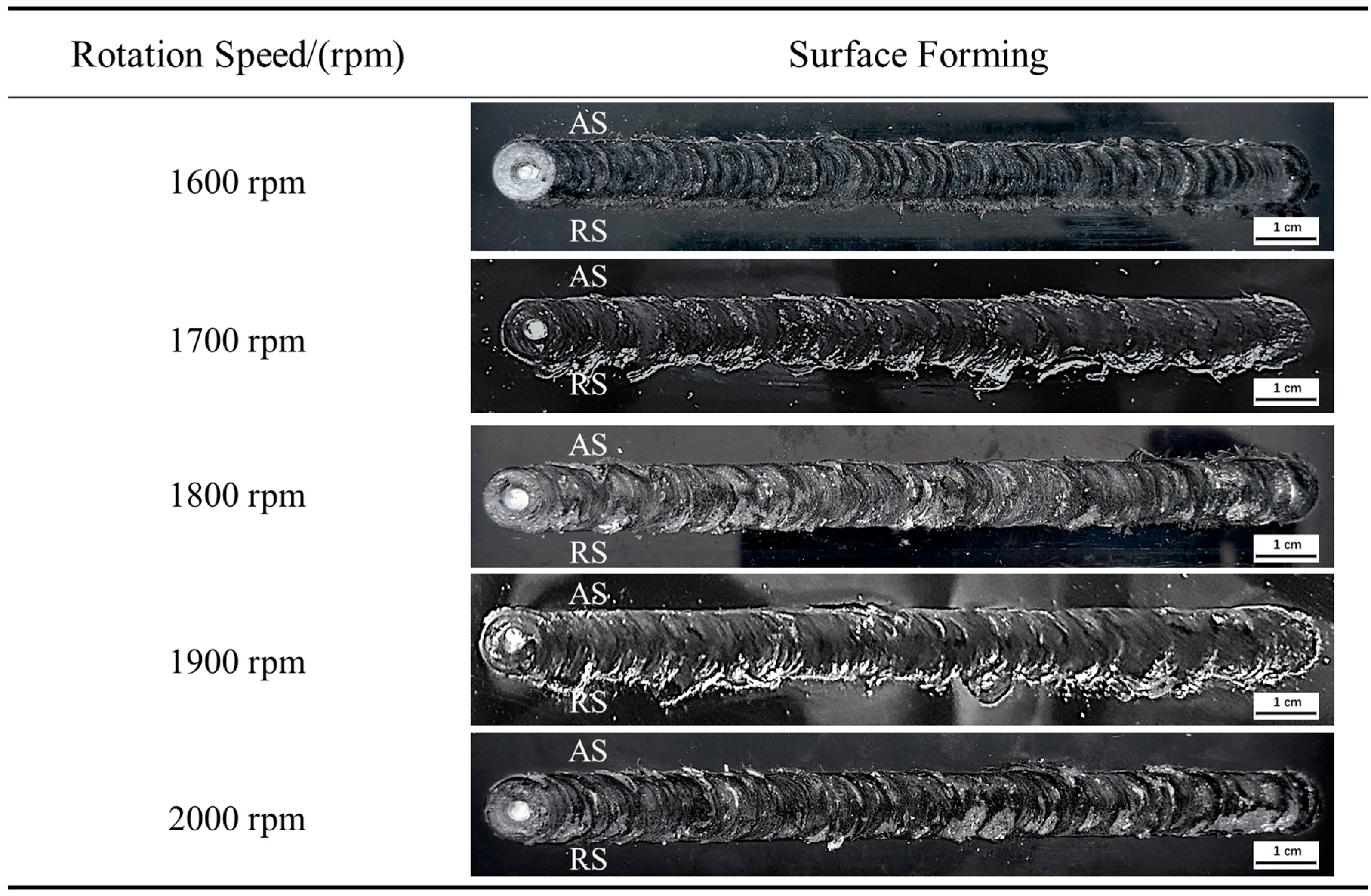
Figure 5 shows the weld surface formed by FSLW at different spindle rotation speeds. In the context of this analysis, AS signifies the advancing side, and RS denotes the retreating side. The tool welding speed of 40 mm/min, inclination angle of 2°, and shoulder plunge depth of 0.2 mm were set as constant values, and the rotation speed was increased from 1600 rpm to 2000 rpm in increments of 100 rpm. When rotation speed is too low, such as 1600 rpm, the low frictional heat during the welding process is insufficient to facilitate adequate flow of the base metal in the weld seam. Compared with the fish scale pattern on the surface of a traditional FSW weld seam, the fish scale pattern of CF-PPS is more prominent and the intervals are more obvious. As the rotation speed continues to increase, the friction heat input also increases, the two materials flow more fully, the weld surface becomes smoother, and at the same time, more aluminum alloy is brought out from below. However, at rotation speeds of 1900 and 2000 rpm, the higher heat input results in excessive plasticization of the material, leading to the removal of a significant quantity of aluminum alloy from the bottom. Large pieces of aluminum chips adhere to the weld surface, and the flash on the forward side is also more obvious.
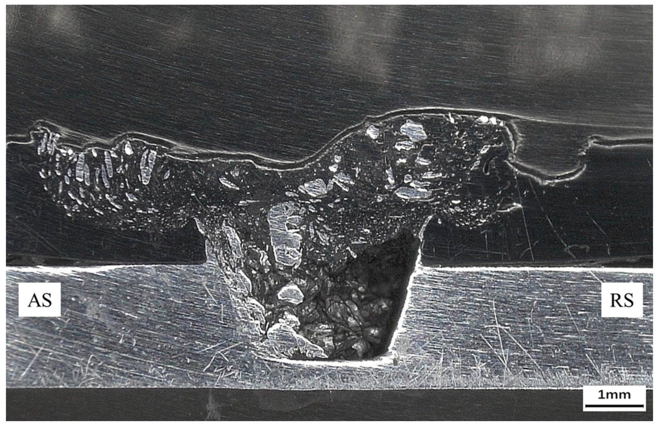
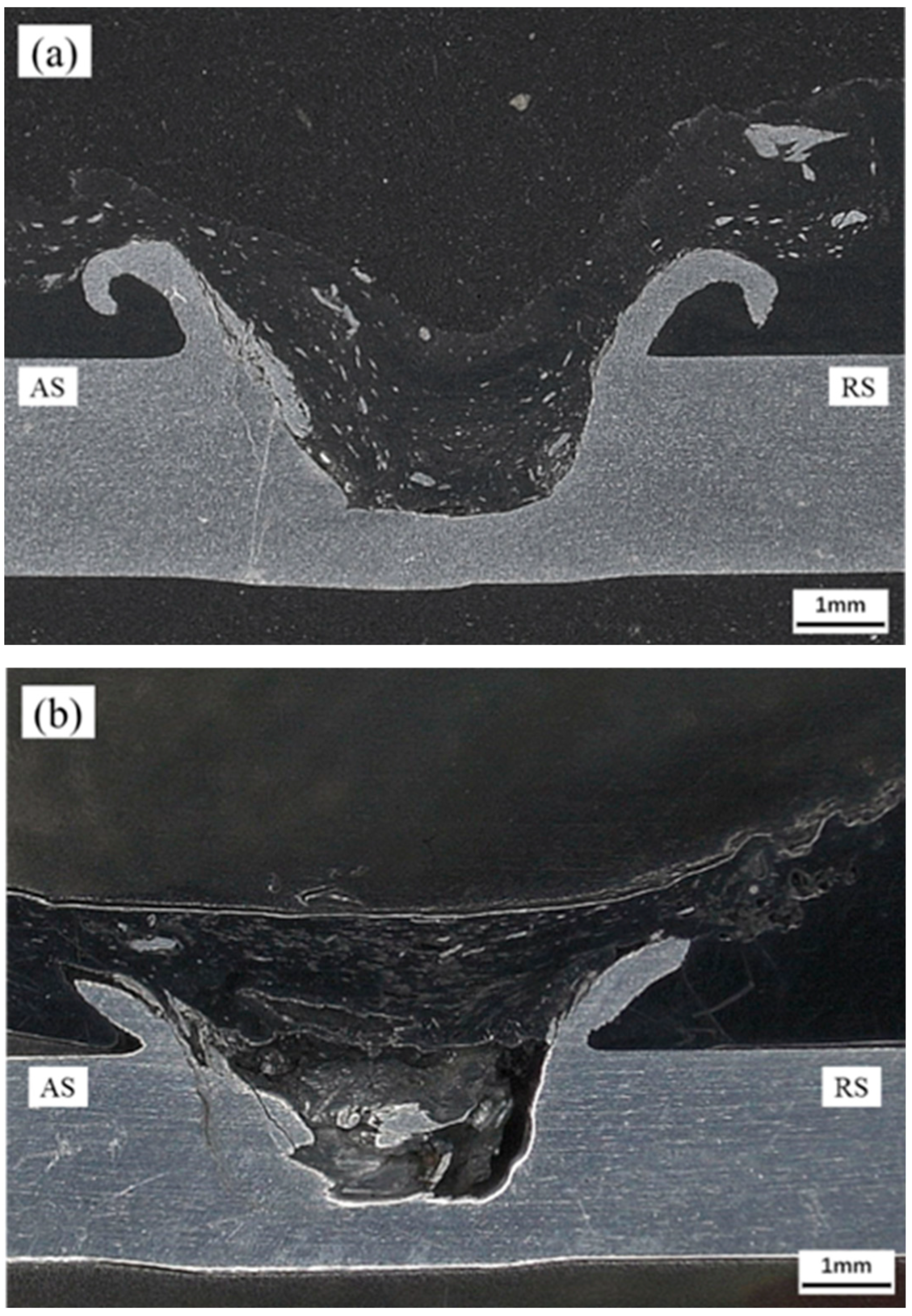
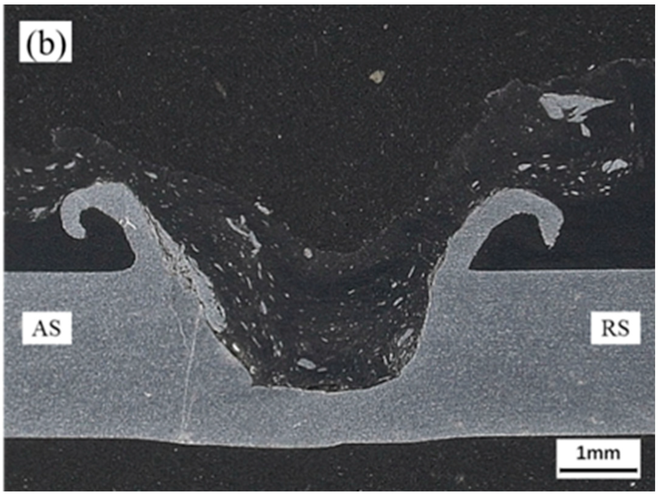
The variation in tensile strength with respect to rotation speed is evident, as shown in Figure 6. With the increase in rotation speed, the joint strength initially increases and then decreases. This change is attributable to the varying connection forms of dissimilar materials at different rotation speeds. Figure 7 shows the cross-sectional morphology of the joint at a rotation speed of 1600 rpm. It is obvious that at a rotation speed of 1600 rpm, the heat input is insufficient, resulting in mainly unplasticized aluminum chips in the stirring zone (SZ). The CF-PPS on the advancing side (AS) does not fill the retreating side (RS), resulting in a significant number of voids, which substantially diminishes the quality of the joints. Consequently, the tensile strength at this time is only 5.95 MPa. As the rotation speed continued to increase, especially at 1800 rpm, the joint strength reached a maximum value of 9.41 MPa, which was 58.1% higher than at 1600 rpm.
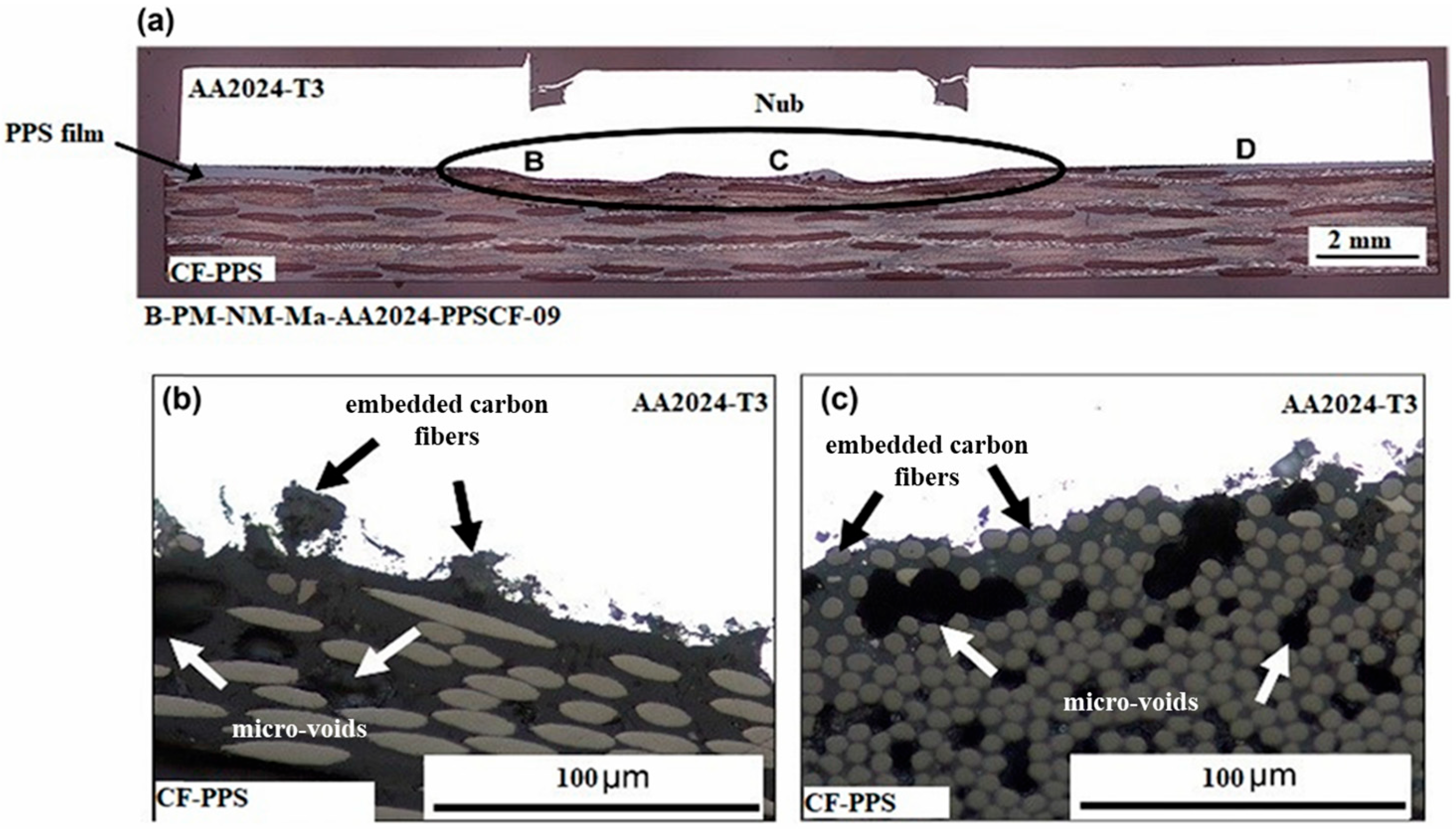
Figure 8 shows the cross-sectional morphology of joints at rotation speeds of 1800 rpm and 2000 rpm. As the rotation speed increases, the friction between the pin and the workpiece becomes more intense, generating greater friction and heat, which accelerates the plasticization process of the metal. Due to the concave structure of the pin shoulder, the plasticized aluminum alloy around the root of the pin is discharged outward during welding, forming a long aluminum anchor [22] at the connection between the two plates, thereby forming an effective mechanical interlocking structure that connects the dissimilar materials [23]. Compared with 2000 rpm, the aluminum anchor formed at 1800 rpm exhibits an inward bending tendency, increasing the adhesion area between the aluminum and the polymer and improving the joint strength. When the rotation speed is increased to 2000 rpm, the composite material is compressed under high thermal action, and part of the material flows out of the center of the weld under the influence of interface pressure, forming holes and reducing the connection strength. Compared to FSLW joints, the FSSW joint interface exhibits a wavy profile [24]. When subjected to axial pressure, the aluminum plate and CFRP undergo deformation, resulting in the formation of a mechanically interlocked structure comprising upper and lower interlocking elements. This structural design is characterized by its simplicity and limited interlocking capacity. Figure 9 illustrates the morphology of an FSSW joint.
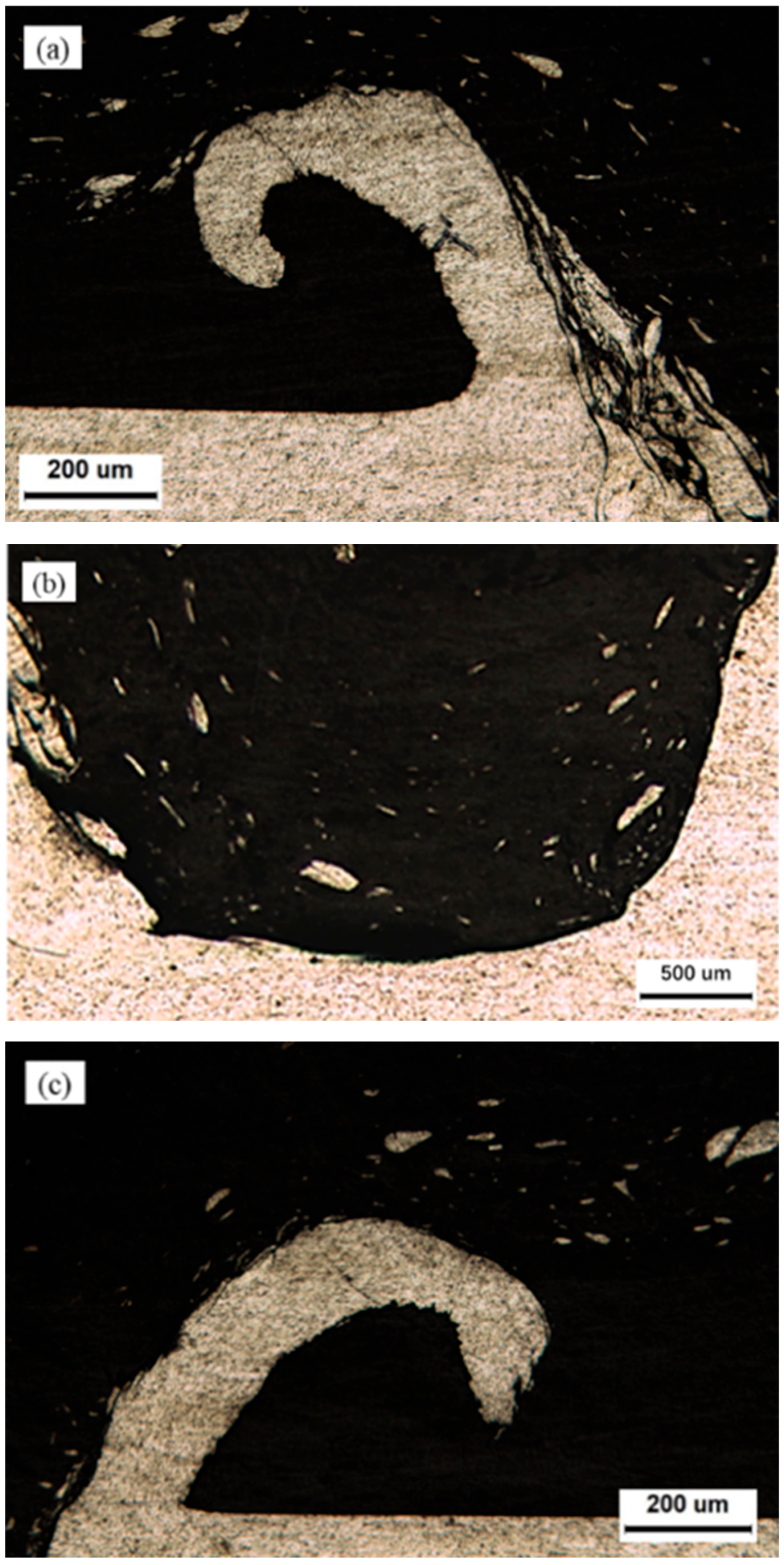
Figure 10 shows the microstructure at different positions in the SZ at a rotation speed of 1800 rpm. In addition to the macro-level mechanical interlocking structure, the micro-level mixture formed by the adhesion between the metal and polymer at the bottom of SZ also contributes to the successful connection of dissimilar materials. The adhesion mechanism is primarily formed by the solidification of melted polymer mixed with aluminum fragments in the cavity. The presence of complex material flow and severe plastic deformation at the AS results in the incomplete formation of aluminum anchor roots at this region. Consequently, during tensile testing, AS experiences failure prior to RS.

3.2. The Effect of Welding Speed on Welding Quality

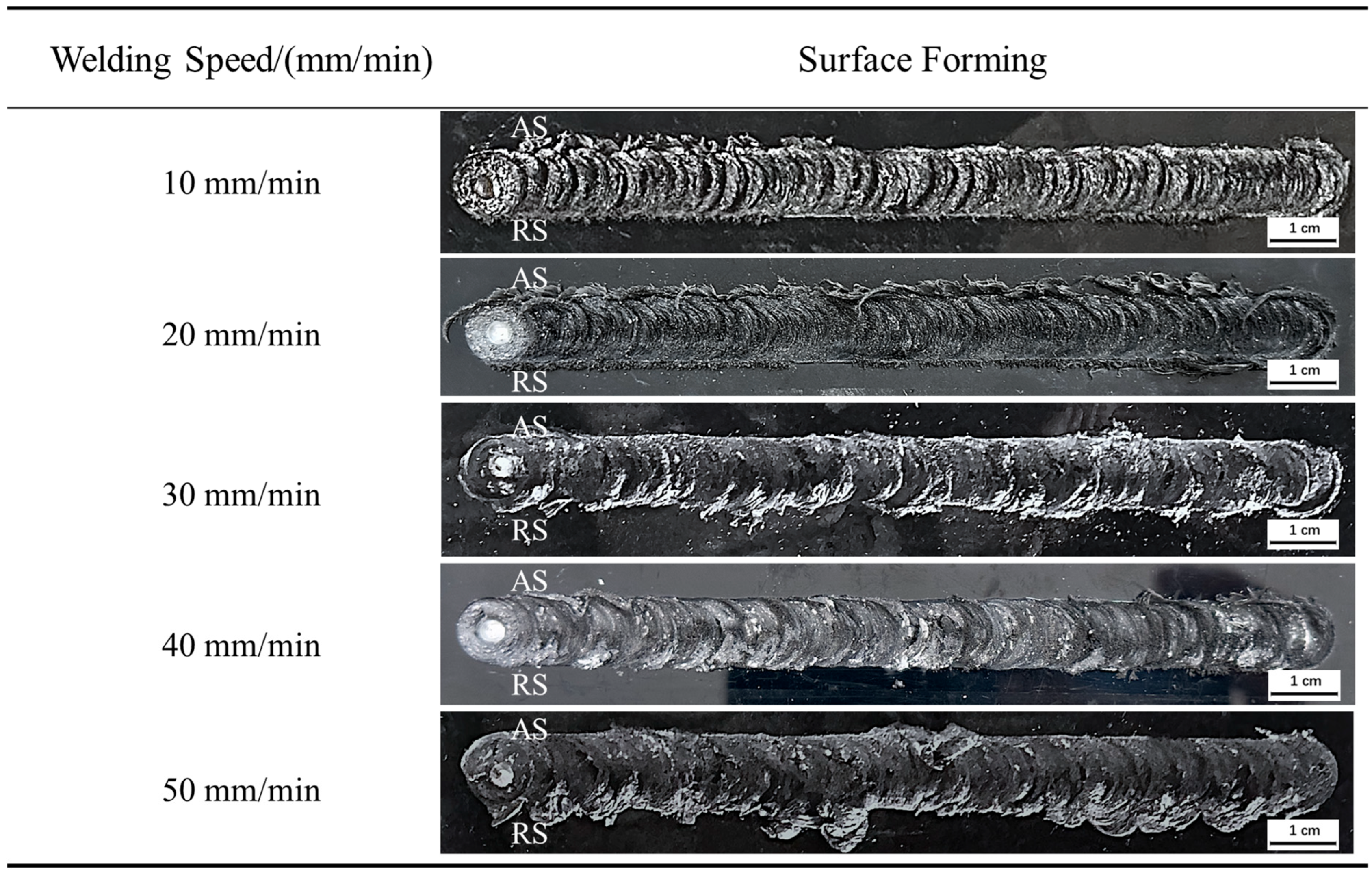
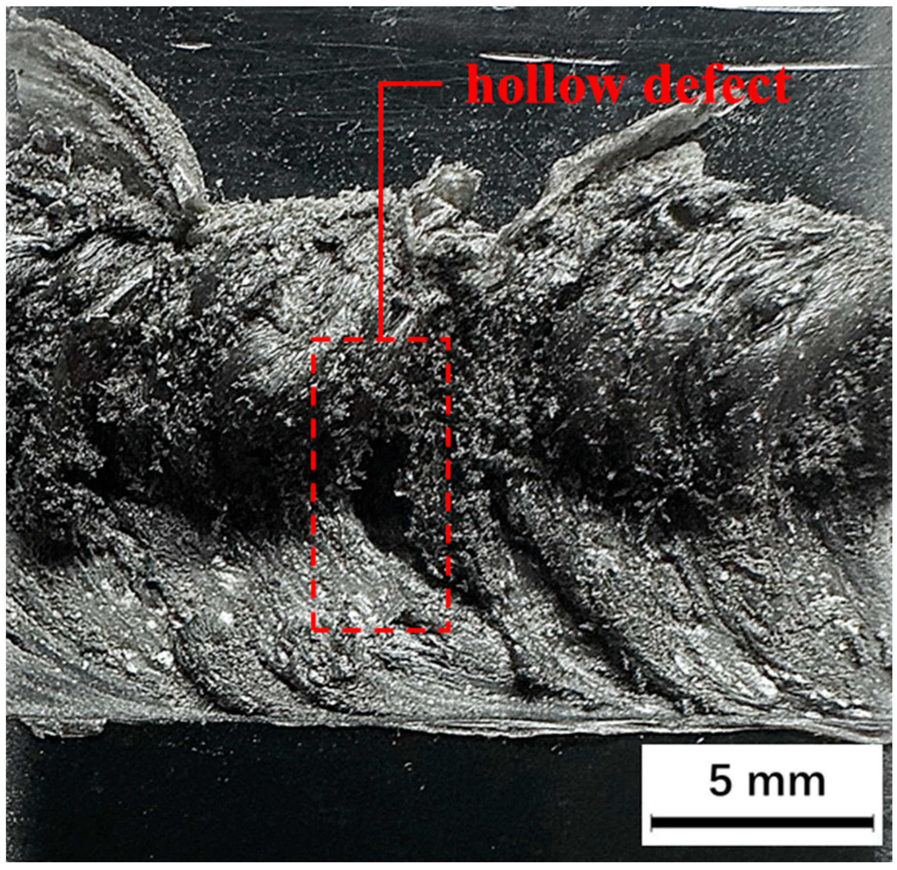
Figure 11 shows the weld surface formed by FSLW at different welding speeds. The rotation speed of 1800 rpm, inclination angle of 2°, and plunge depth of 0.2 mm were set as constant values, and the tool welding speed was increased from 10 to 50 mm/min in 10 mm/min increments. When the welding speed is below 20 mm/min, the weld surface is rough, and the fish scale patterns formed by the composite material become more compact and prominent. Although a low welding speed can increase the thermal input during the welding process, due to the low specific heat and thermal conductivity of CF-PPS, the material undergoes rapid deformation upon heating. Additionally, the low welding speed fails to promptly supply the plasticized base material forward, resulting in the CF-PPS directly forming fish scale patterns at the original location. As the welding speed gradually increases, the flash on the AS also continues to increase. When the welding speed reaches 50 mm/min, distinct hollow defects appear on the surface, which significantly impair welding quality. The hollow defects are shown in Figure 12.
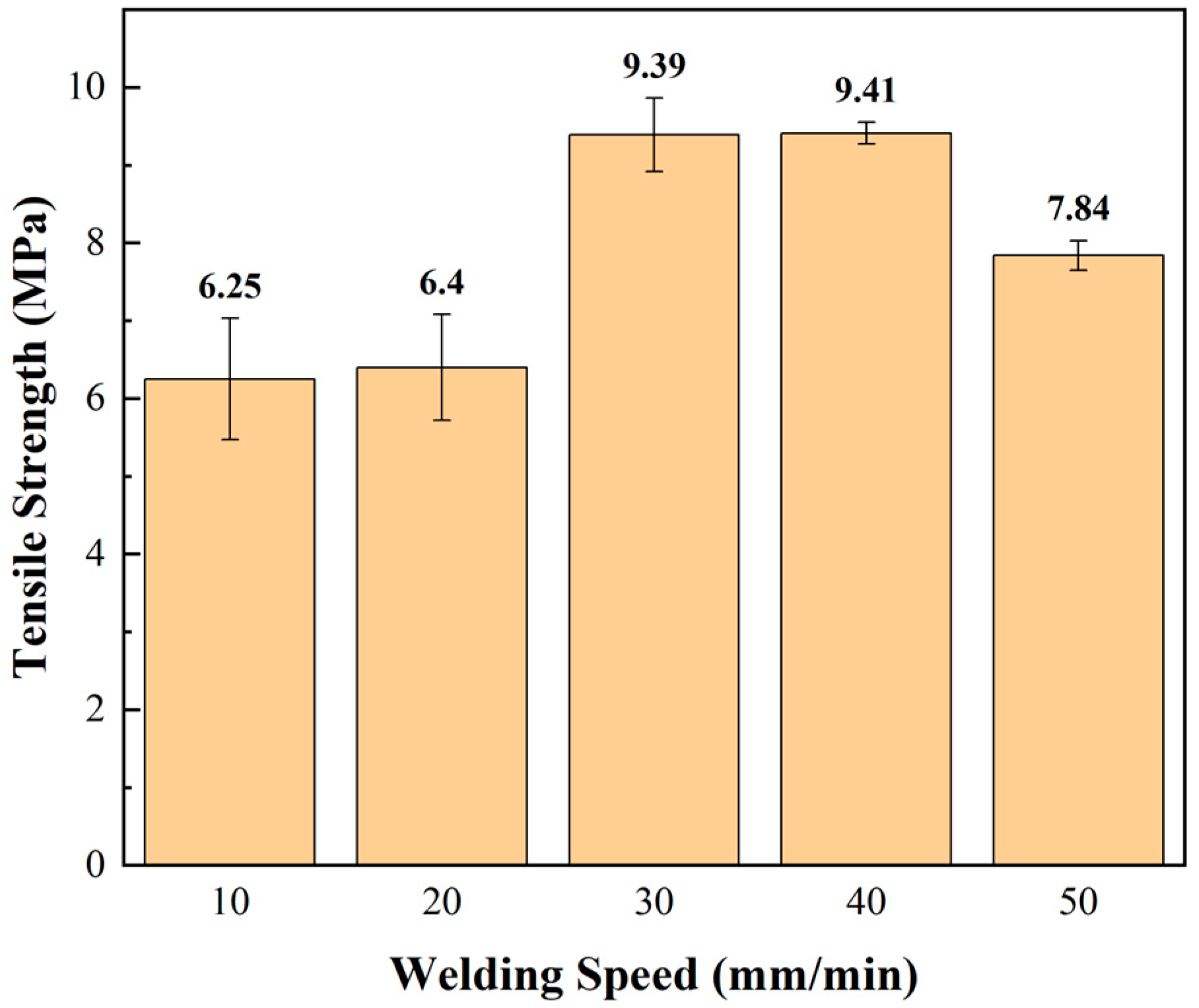
The tensile strength at different welding speeds is illustrated in Figure 13. The tensile strength of the joint demonstrates an initial increase, followed by a subsequent decrease, as the welding speed increases. The significant variation in strength between welding speeds below 20 mm/min and above 30 mm/min is also closely related to the formation of aluminum anchors. Figure 14 shows the cross-sectional morphology of the joint at 10 mm/min. It can be seen that a welding speed of 10 mm/min cannot form a complete interlocking structure. A small aluminum anchor can be generated on the RS, but the complex flow on the AS results in an incomplete connection. The low welding speed of 10 mm/min increases the friction time between the stirring pin and the workpiece, providing more heat and allowing the plasticized aluminum alloy to fill more completely. Hollow defects were observed on the retreating side, a phenomenon that has also been observed in the context of resistance welding [26] and laser welding [27] of thermoplastic composites. Due to the low thermal conductivity of CF-PPS, the heat generated during welding dissipates slowly. Additionally, the low welding speed fails to fill the base material forward, causing part of the polymer matrix to decompose under heat and form a gas phase, which expands within the CF-PPS material to form cavities. This ultimately manifests as upward expansion of the composite material on the RS with fewer aluminum particles inside. Goushegir et al. [28] investigated the presence of micro-voids in Al/CF-PPS friction-welding joints, concluding that these voids do not cause thermomechanical degradation in the composite material.
Figure 15 shows the cross-sectional morphology of the joint at 50 mm/min. When the welding speed is high, the aluminum anchors on both sides extend outward significantly. The reduced heat input generated by the shoulder results in a less substantial softening and reduction in fluidity of the CF-PPS, leading to inadequate filling of the SZ. This, in turn, gives rise to the formation of gaps within the joint, thereby compromising its quality.

3.3. The Effect of Plunge Depth on Welding Quality

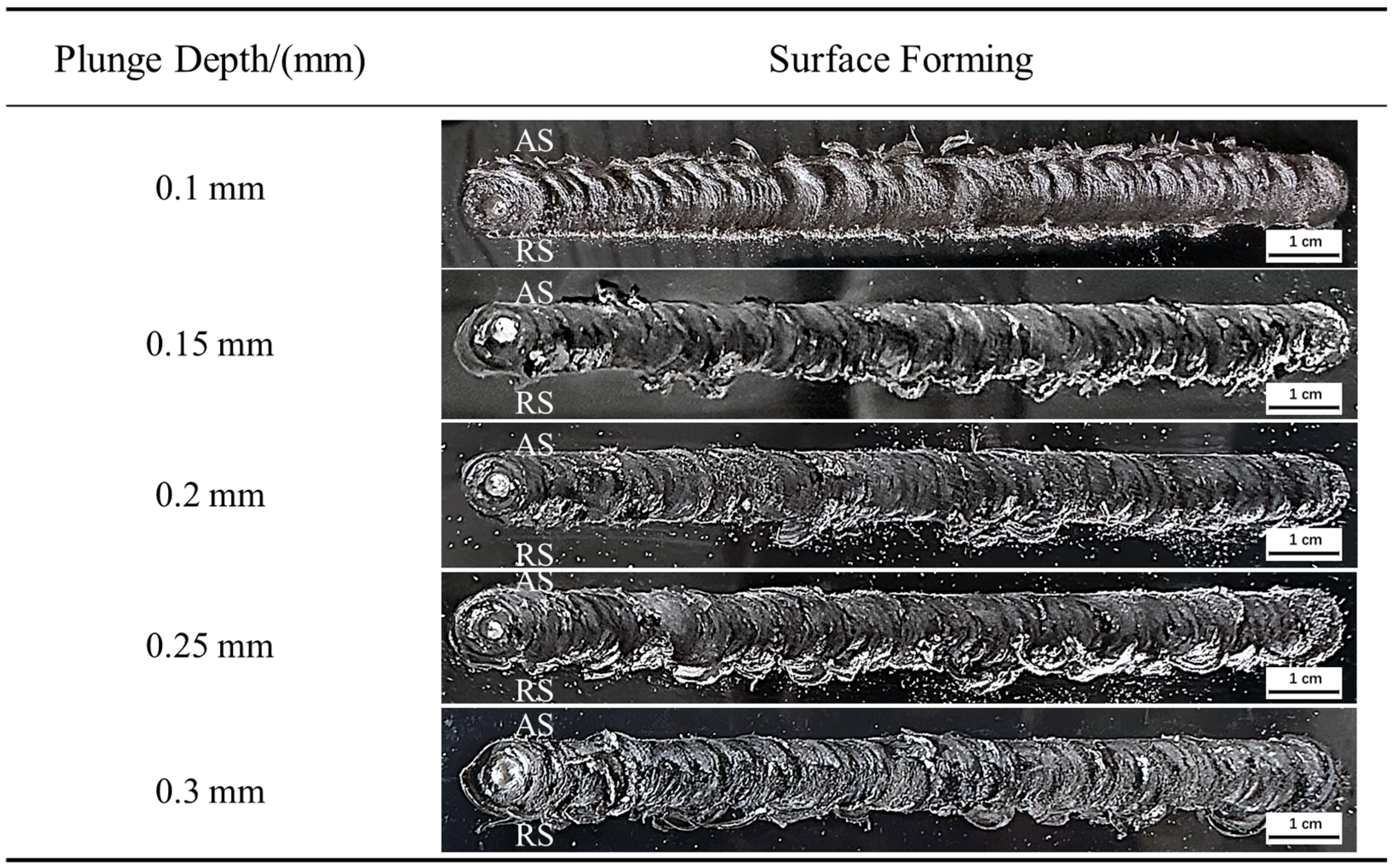
Figure 16 shows the weld surface formed by FSLW under different shoulder plunge depths. Based on previous studies on rotation speed and welding speed, the rotation speed was set to 1800 rpm, the welding speed to 40 mm/min, and the inclination angle to 2°, while the plunge depth was increased from 0.1 mm to 0.3 mm in increments of 0.05 mm. It is evident that when the plunge depth is less than 0.2 mm, the presence of other obvious defects is minimal, with the exception of the shallow weld depth. However, as the plunge depth increases from 0.2 mm, the occurrence of flash begins to manifest on the AS, the weld begins to thin, and fine aluminum chips are continuously carried out from below, seriously affecting the strength of the joints.
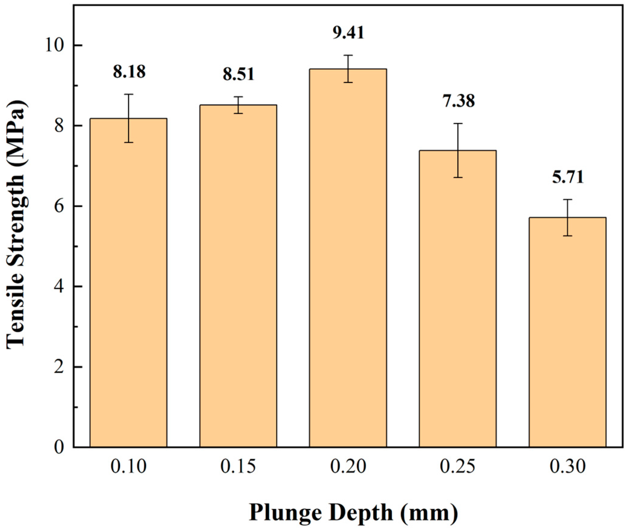
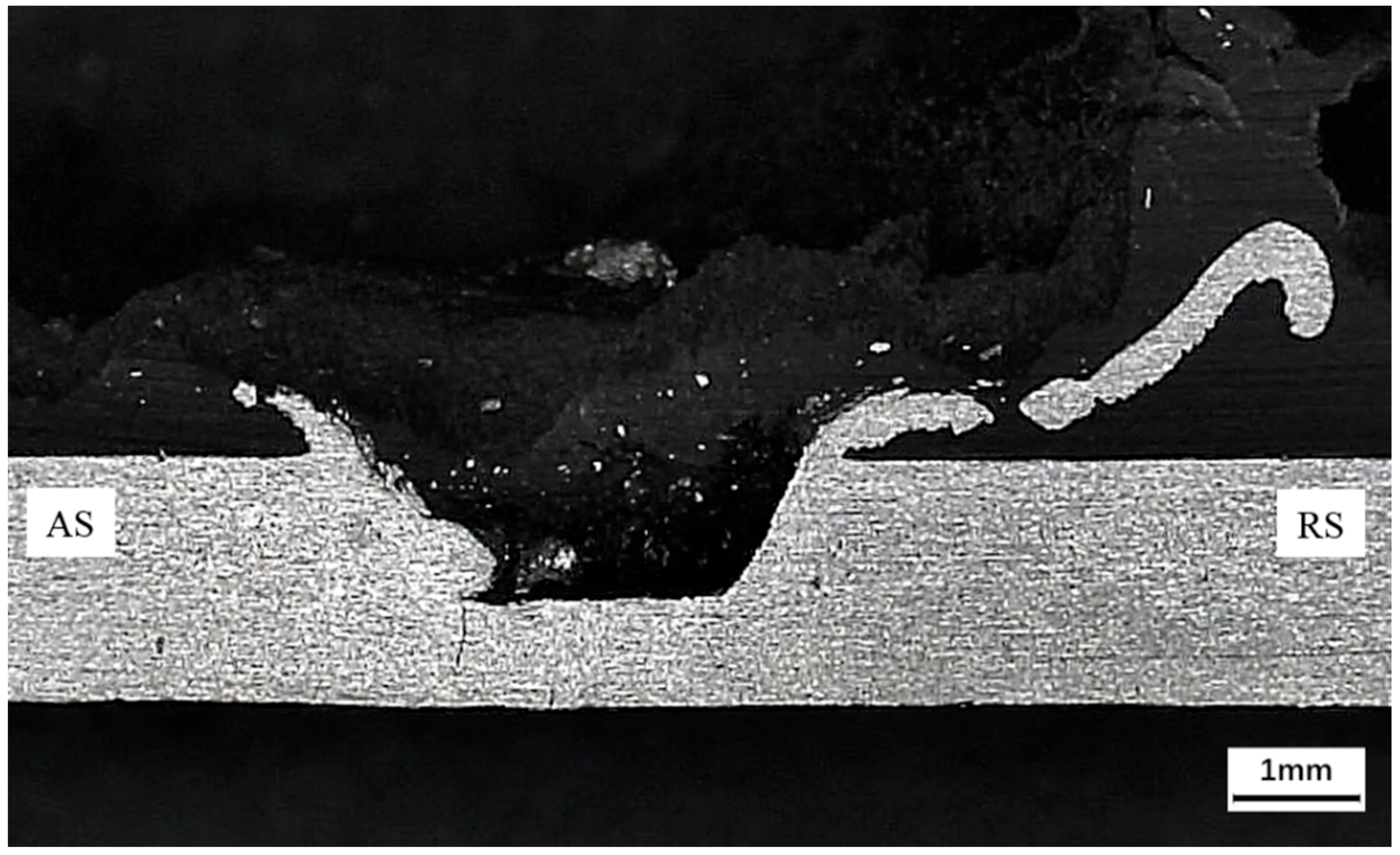
As illustrated in Figure 17, the tensile strength and its variation under different plunge depths are demonstrated. When the plunge depth increased from 0.1 to 0.2 mm, the joint strength exhibited a gradual increase. However, when the plunge depth increased from 0.2 to 0.3 mm, the weld seam underwent a substantial reduction in thickness, accompanied by a significant decrease in tensile strength. Figure 18 shows the microstructure of joints at plunge depths of 0.1 mm and 0.2 mm. It can be seen that when the rotation speed and welding speed, the two main parameters affecting the heat input of the welding process, are appropriately selected and kept constant, both 0.1 mm and 0.2 mm plunge depths can form effective mechanical interlocking structures. When the plunge depth was increased to 0.3 mm, the cross-sectional morphology of the joint was as shown in Figure 19. The deeper plunge depth causes a large amount of aluminum anchor to overflow on both sides, and the excessively long aluminum anchor on the RS is fractured by the substantial axial pressure during the welding process. The plasticized CF-PPS also accumulate in the RS, resulting in a significant reduction in tensile strength.
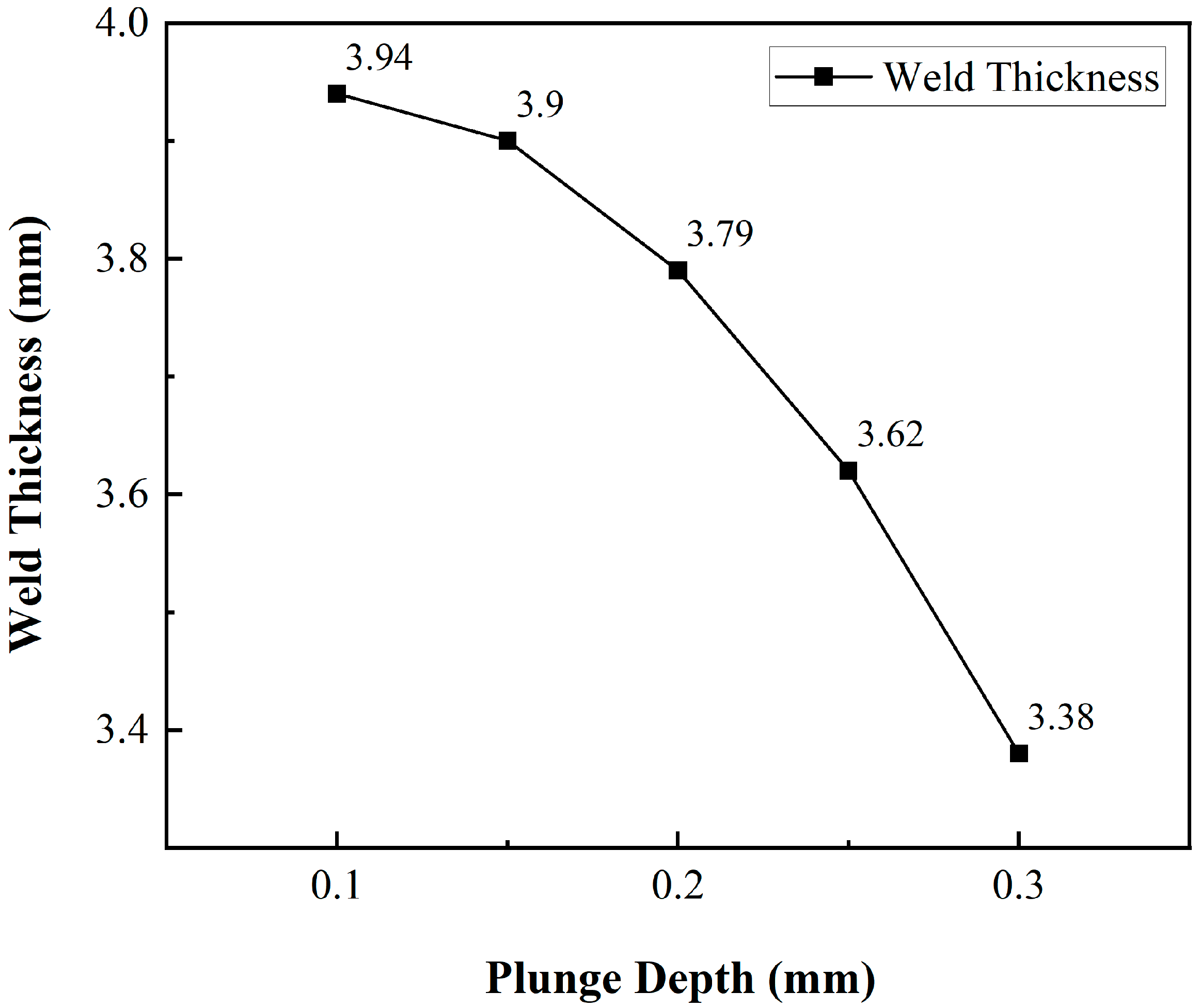
As illustrated in Figure 20, the weld thickness varies with different plunge depth. It has been observed that as the plunge depth increases, the weld thickness undergoes a continuous decrease, with the thinning becoming increasingly pronounced. When the plunge depth reaches 0.3 mm, the weld thickness is only 84.5% of the original value. Esteves et al. [29] found that increasing the plunge depth enhances contact between the aluminum alloy and CF-PPS, thereby improving interfacial adhesion between dissimilar materials. However, it has been demonstrated that excessive plunge depth increases axial force, leading to significant joint gaps and voids at the weld center. This, in turn, severely compromises the interfacial bonding structure. Consequently, the application of an appropriate plunge depth (0.1–0.2 mm) has been demonstrated to be an effective method of enhancing the quality of welding.

4. Conclusions

This study proposes a novel approach to address the disparate joining of aluminum alloy and CF-PPS through the friction stir lap welding, wherein the composite material is positioned on the upper surface and the aluminum alloy on the lower surface. Compared with the currently widely studied friction stir spot welding technology, this method is characterized by its ease of operation and its ability to reduce the issue of spot welding stress concentration. Therefore, single-factor experiments were conducted on the FSLW of AA6061-T6 and CF-PPS. The microstructure and performance changes in the joints under FSLW were then analyzed. The primary conclusions are drawn as follows:
  • The macro mechanical interlocking structure is the main connection form that facilitates the successful connection of aluminum alloy and CF-PPS dissimilar materials. The concave shoulder facilitates the outward extension of the aluminum at the edge of the stirring zone, thereby forming a hook that serves to connect the upper and lower plates. The inward curvature of the aluminum anchor serves to augment the connection area between the two plates, thereby enhancing the tensile strength of the weld.
  • It has been demonstrated that, under welding parameters of 1800 rpm rotation speed, 40 mm/min welding speed, and 0.2 mm plunge depth, the tensile strength of the joint can reach a maximum value of 9.41 MPa. Concurrently, the microscopic mixture formed by the adhesion between the metal and polymer inside the SZ also increases the tensile strength of the joint.
  • At low rotation speeds (1600 rpm) and low welding speeds (10 mm/min), an effective mechanical interlocking structure cannot be formed at the center of the weld, which weakens the connection strength. The low rotation speed fails to provide sufficient frictional heat input, resulting in incomplete plasticization of the aluminum below, failure to form aluminum anchors on both sides of the SZ, and the formation of hollow at the bottom. The low welding speed leads to excessive heat generation by friction, resulting in thermal decomposition of a portion of the resin matrix in CF-PPS, which subsequently forms a gas phase. This gas phase expands within the base material, creating cavities, while the aluminum anchors generated on the AS undergo significant damage.
  • When the rotation speed and welding speed, the two main parameters affecting the heat input of the welding process are appropriately selected and kept constant. A smaller plunge depth can form an effective mechanical interlocking structure. Excessive plunge depth will thin the weld and reduce the joint strength.
In summary, this study proposes a novel technical approach for welding Al/CF-PPS composites, identifies optimal parameters for defect-free joints, and elucidates the bonding mechanism and changes in mechanical properties. To address these challenges, further research is necessary to enhance the joint quality and ensure its compliance with practical engineering demands.

Author Contributions

Conceptualization, W.X.; methodology, Q.F. and Y.W.; validation, J.W. and S.N.; formal analysis, W.X.; investigation, Q.F. and W.X.; writing—original draft preparation, W.X.; writing—review and editing, Q.F., J.W., S.N. and M.L.; supervision, Q.F., Y.L., Y.W. and M.L.; project administration, Q.F., Y.W. and Y.L.; funding acquisition, Q.F. All authors have read and agreed to the published version of the manuscript.

Funding

This research was funded by the National Natural Science Foundation of China (Grant No. 52175343).

Data Availability Statement

The original contributions presented in the study are included in the article, further inquiries can be directed to the corresponding author.

Conflicts of Interest

Author Yongyong Lin was employed by the company Aerospace Engineering Equipment (Suzhou) Co., Ltd. The remaining authors declare that the research was conducted in the absence of any commercial or financial relationships that could be construed as a potential conflict of interest.

References

  1. Zhang, W.; Xu, J. Advanced lightweight materials for Automobiles: A review. Mater. Des. 2022, 221, 110994. [Google Scholar] [CrossRef]
  2. Lin, Y.; Qian, W.; Lei, L.; Liu, Y.; Zhang, J.; Liu, J.; Kong, W.; Hu, Y.; Shi, Y.; Wu, Z.; et al. Structural integrity issues of composite materials and structures in future transportation equipment. Compos. Struct. 2025, 358, 118943. [Google Scholar] [CrossRef]
  3. Asmael, M.; Safaei, B.; Kalaf, O.; Zeeshan, Q.; Aldakheel, F.; Nasir, T.; Yang, Z. Recent developments in tensile properties of friction welding of carbon fiber-reinforced composite: A review. Nanotechnol. Rev. 2022, 11, 1408–1436. [Google Scholar] [CrossRef]
  4. Liu, Y.; Wang, X.; Zhou, L.; Zhao, H.; Han, X.; Tan, C.; Song, X. Achievement of high-strength Al/CFRP hybrid joint via high-speed friction stir lap joining and laser texturing pretreatment parameters variation. Thin-Walled Struct. 2024, 199, 111762. [Google Scholar] [CrossRef]
  5. Wang, S.; Xu, Y.; Wang, W.; Tian, Y.; Zhang, X.; Huang, H.; Zheng, D. Enhancing interfacial bonding in friction stir lap welding of light metal and carbon fiber reinforced polymer composite. J. Manuf. Process. 2022, 83, 729–741. [Google Scholar] [CrossRef]
  6. Zhang, J.; Lin, G.; Vaidya, U.; Wang, H. Past, present and future prospective of global carbon fibre composite developments and applications. Compos. Part B Eng. 2023, 250, 110463. [Google Scholar] [CrossRef]
  7. Pramanik, A.; Basak, A.; Dong, Y.; Sarker, P.; Uddin, M.; Littlefair, G.; Dixit, A.; Chattopadhyaya, S. Joining of carbon fibre reinforced polymer (CFRP) composites and aluminium alloys—A review. Compos. Part A Appl. Sci. Manuf. 2017, 101, 1–29. [Google Scholar] [CrossRef]
  8. Huang, Y.; Meng, X.; Xie, Y.; Wan, L.; Lv, Z.; Cao, J.; Feng, J. Friction stir welding/processing of polymers and polymer matrix composites. Compos. Part A Appl. Sci. Manuf. 2018, 105, 235–257. [Google Scholar] [CrossRef]
  9. Li, J.; Dong, H.; Tang, Z.; Li, P.; Wu, B.; Ma, Y.; Huang, L.; Zhang, L.; Li, C.; Xiong, J. Influence of surface pretreatment on the bonding mechanism and mechanical properties of AA5052/CFRP friction stir spot welded joint. J. Manuf. Process. 2023, 105, 112–123. [Google Scholar] [CrossRef]
  10. MirHashemi, S.; Amadeh, A.; Khodabakhshi, F. Effects of SiC nanoparticles on the dissimilar friction stir weldability of low-density polyethylene (LDPE) and AA7075 aluminum alloy. J. Mater. Res. Technol. 2021, 13, 449–462. [Google Scholar] [CrossRef]
  11. Ingen, V.; Wijngaarden, V.; Iii, S. Development of the gulfstream G650 induction welded thermoplastic elevators and rudder. In Proceedings of the Sampe Seattle 2010, Seattle, WA, USA, 17–20 May 2010; Available online: https://www.researchgate.net/publication/332403057 (accessed on 13 April 2019).
  12. Lyu, Y.; Wu, J.; Zhang, H.; Brádaigh, C.M.Ó.; Yang, D. Effects of thermal process conditions on crystallinity and mechanical properties in material extrusion additive manufacturing of discontinuous carbon fibre reinforced polyphenylene sulphide composites. J. Compos. Mater. 2023, 57, 3775–3787. [Google Scholar] [CrossRef]
  13. Eixeres, B.; Sanchez-Caballero, S.; Peydro, M.; Parres, F.; Selles, M. Influence of injection molding process conditions on the mechanical properties of CF-PPS/PTFE composites. Alex. Eng. J. 2025, 123, 381–391. [Google Scholar] [CrossRef]
  14. André, N.M.; dos Santos, J.F.; Amancio-Filho, S.T. Evaluation of Joint Formation and Mechanical Performance of the AA7075-T6/CFRP Spot Joints Produced by Frictional Heat. Materials 2019, 12, 891. [Google Scholar] [CrossRef]
  15. Schäfer, H.; Blaga, L.; Stöver, E.; Klusemann, B. Refill friction stir spot welding of thermoplastic composites: Case study on Carbon-fiber-reinforced polyphenylene sulfide. Thin-Walled Struct. 2023, 191, 111037. [Google Scholar] [CrossRef]
  16. Li, H.; Liu, X.-S.; Zhang, Y.; Yuan, T.; Hodúlová, E.; Šimeková, B.; Bober, M.; Senkara, J.; Li, Z.-X. Influence of the rotation speed on the interface microstructure and joining quality of aluminum alloy 6061/CF-PPS joints produced by refill friction stir spot welding. Weld. World 2022, 66, 923–933. [Google Scholar] [CrossRef]
  17. Sandeep, R.; Nagarajan, B.M.; Kumar, M.P.; Jose, B.; Manoharan, M.; Natarajan, A. Influence of welding environment on joint characteristics of friction stir lap welded AA7475-PPS polymer hybrid joints. Mater. Lett. 2023, 349, 134781. [Google Scholar] [CrossRef]
  18. Huang, Y.; Meng, X.; Xie, Y.; Li, J.; Si, X.; Fan, Q. Improving mechanical properties of composite/metal friction stir lap welding joints via a taper-screwed pin with triple facets. J. Mech. Work. Technol. 2019, 268, 80–86. [Google Scholar] [CrossRef]
  19. Derazkola, H.A.; Elyasi, M. The influence of process parameters in friction stir welding of Al-Mg alloy and polycarbonate. J. Manuf. Process. 2018, 35, 88–98. [Google Scholar] [CrossRef]
  20. Derazkola, H.A.; Fard, R.K.; Khodabakhshi, F. Effects of processing parameters on the characteristics of dissimilar friction-stir-welded joints between AA5058 aluminum alloy and PMMA polymer. Weld. World 2018, 62, 117–130. [Google Scholar] [CrossRef]
  21. GB/T 7124-2008; Adhesives—Determination of Tensile Lap-Shear Strength of Rigid-to-Rigid Bonded Assemblies. Standardization Administration of China: Beijing, China, 2008.
  22. Haghshenas, M.; Khodabakhshi, F. Dissimilar friction-stir welding of aluminum and polymer: A review. Int. J. Adv. Manuf. Technol. 2019, 104, 333–358. [Google Scholar] [CrossRef]
  23. Derazkola, H.A.; Khodabakhshi, F.; Simchi, A. Friction-stir lap-joining of aluminium-magnesium/poly-methyl-methacrylate hybrid structures: Thermo-mechanical modelling and experimental feasibility study. Sci. Technol. Weld. Join. 2018, 23, 35–49. [Google Scholar] [CrossRef]
  24. André, N.M.; Alessio, R.P.; dos Santos, J.F.; Amancio-Filho, S.T. Microscale Damage Evolution and Failure Behavior of Metal–Composite Friction Spot Joints: Modelling and Experimental Analyses. Metals 2022, 12, 2080. [Google Scholar] [CrossRef]
  25. André, N.M.; Goushegir, S.M.; dos Santos, J.F.; Canto, L.B.; Amancio-Filho, S.T. Friction Spot Joining of aluminum alloy 2024-T3 and carbon-fiber-reinforced poly(phenylene sulfide) laminate with additional PPS film interlayer: Microstructure, mechanical strength and failure mechanisms. Compos. Part B Eng. 2016, 94, 197–208. [Google Scholar] [CrossRef]
  26. Ren, S.; Ma, Y.; Saeki, S.; Iwamoto, Y.; Chen, C.; Ma, N. Fracture mechanism and strength evaluation of Al5052/CFRP joint produced by coaxial one-side resistance spot welding. Compos. Struct. 2020, 252, 112766. [Google Scholar] [CrossRef]
  27. Ren, S.; Shen, Y.; Chen, H.; Zheng, W.; Ma, Y.; Feng, D.; Yang, J. Investigation on the joining process and strength of laser circle welding between Al5052 and CFRP dissimilar materials. J. Manuf. Process. 2024, 120, 426–434. [Google Scholar] [CrossRef]
  28. Goushegir, S.M.; dos Santos, J.F.; Amancio-Filho, S.T. Friction Spot Joining of aluminum AA2024/carbon-fiber reinforced poly(phenylene sulfide) composite single lap joints: Microstructure and mechanical performance. Mater. Des. 2014, 54, 196–206. [Google Scholar] [CrossRef]
  29. Esteves, J.V.; Goushegir, S.M.; dos Santos, J.F.; Canto, L.B.; Hage, E., Jr.; Amancio-Filho, S.T. Friction spot joining of aluminum AA6181-T4 and carbon fiber-reinforced poly(phenylene sulfide): Effects of process parameters on the microstructure and mechanical strength. Mater. Des. 2015, 66, 437–445. [Google Scholar] [CrossRef]
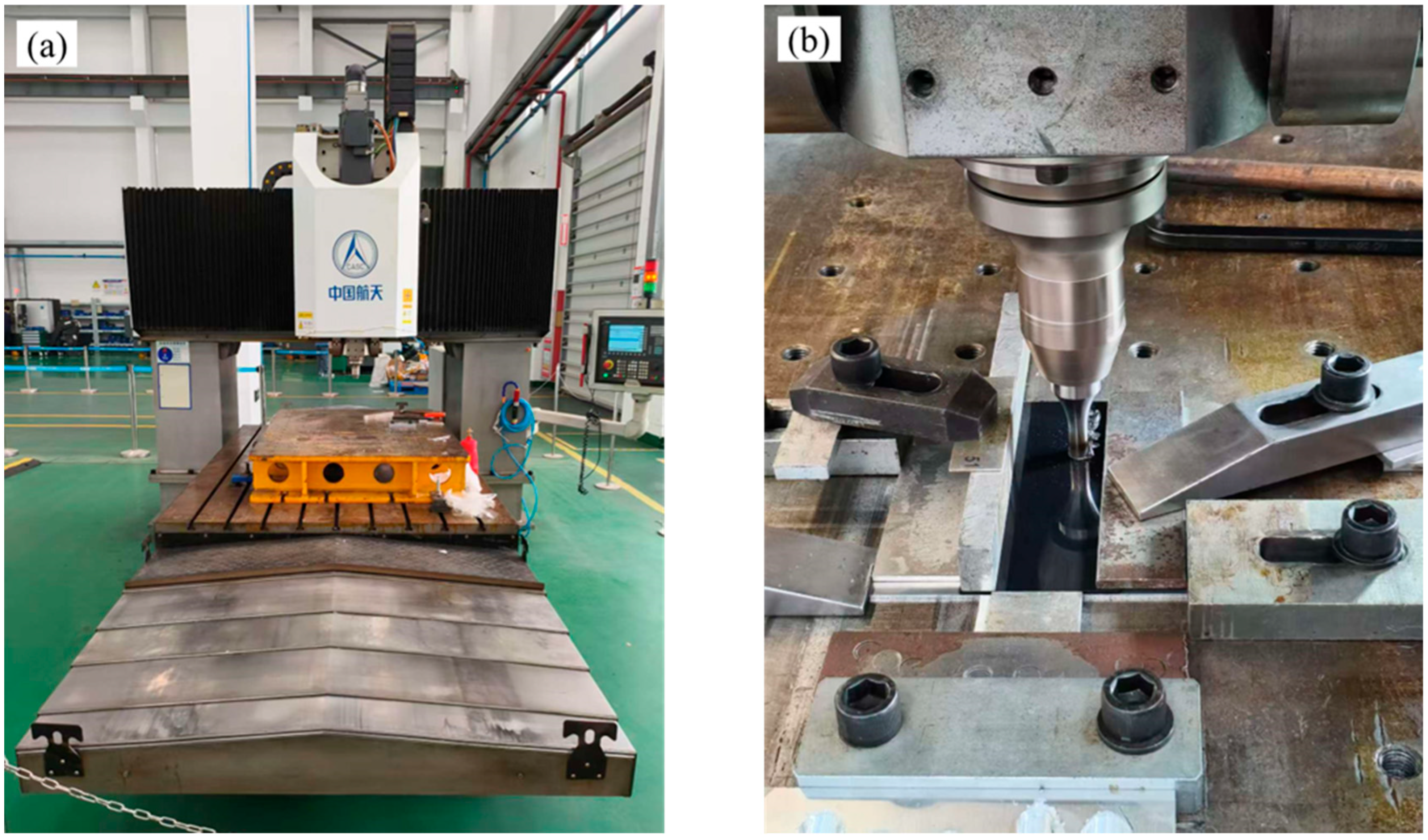
Figure 1. Set-up of equipment for FSLW: (a) FSLW equipment used in this study; (b) welding clamping diagram.
Metals 15 01049 g001
Figure 2. (a) Actual image of the pin; (b) 3D design drawing.
Metals 15 01049 g002
Figure 3. The lap joint configuration: ① tensile test specimen; ② metallographic specimen.
Metals 15 01049 g003
Figure 4. Geometric configuration of the tensile test specimens (all dimensions in mm).
Metals 15 01049 g004
Figure 5. Surface forming of FSLW at different rotation speeds.
Metals 15 01049 g005
Figure 6. Tensile strength of FSLW joints at different rotation speeds.
Metals 15 01049 g006
Figure 7. Cross-sectional morphology of the joint at 1600 rpm.
Metals 15 01049 g007
Figure 8. Cross-sectional morphology of the joints at (a) 1800 rpm, (b) 2000 rpm.
Metals 15 01049 g008
Figure 9. FSSW Joint Morphology: (a) cross-sectional Macrostructure, (b) molten polymer of Al surface, (c) deformed aluminum. Adapted from Ref. [25].
Metals 15 01049 g009
Figure 10. Microstructure at different positions in the SZ at 1800 rpm. (a) AS; (b) Bottom; (c) RS.
Metals 15 01049 g010
Figure 11. Surface forming of FSLW at different welding speeds.
Metals 15 01049 g011
Figure 12. Surface hollow defects at the welding speed of 50 mm/min.
Metals 15 01049 g012
Figure 13. Tensile strength of FSLW joints at different welding speeds.
Metals 15 01049 g013
Figure 14. Cross-sectional morphology of the joint at 10 mm/min.
Metals 15 01049 g014
Figure 15. Cross-sectional morphology of the joint at 50 mm/min.
Metals 15 01049 g015
Figure 16. Surface forming of FSLW under different plunge depth.
Metals 15 01049 g016
Figure 17. Tensile strength of FSLW joints under different plunge depth.
Metals 15 01049 g017
Figure 18. Cross-sectional morphology of joints at the plunge depth of (a) 0.1 mm, (b) 0.2 mm.
Metals 15 01049 g018aMetals 15 01049 g018b
Figure 19. Cross-sectional morphology of the joint at 0.3 mm.
Metals 15 01049 g019
Figure 20. Weld thickness at different plunge depth.
Metals 15 01049 g020
Table 1. Chemical composition of AA6061-T6.
Chemical Composition (wt%)
MgFeSiCuZnMnCrAl
0.8–1.20.70.4–0.80.15–0.40.250.150.04–0.35Base
Table 2. Mechanical properties of AA6061-T6.
Mechanical Properties
Yield Strength
(MPa)
Tensile Strength
(MPa)
Extension Rate
(%)
2403108
Table 3. Physical and mechanical properties of CF-PPS.
Density (g/cm3)Melting Temperature (°C)Tensile Strength (MPa)In-Plane Strength (MPa)Extension Rate (%)
1.352951701191.2
Table 4. The process parameters of FSLW.
FSLW Experimental ProgramRotation SpeedWelding
Speed
Plunge DepthInclination Angle
The effect of rotation speed1600 rpm40 mm/min0.2 mm
1700 rpm
1800 rpm
1900 rpm
2000 rpm
The effect of welding speed1800 rpm10 mm/min0.2 mm
20 mm/min
30 mm/min
40 mm/min
50 mm/min
The effect of plunge depth1800 rpm40 mm/min0.1 mm
0.15 mm
0.2 mm
0.25 mm
0.3 mm
Disclaimer/Publisher’s Note: The statements, opinions and data contained in all publications are solely those of the individual author(s) and contributor(s) and not of MDPI and/or the editor(s). MDPI and/or the editor(s) disclaim responsibility for any injury to people or property resulting from any ideas, methods, instructions or products referred to in the content.