Abstract
Residual stress remains a significant challenge in the widespread adoption of the Laser Powder Bed Fusion (LPBF) process, due to its detrimental impact on dimensional accuracy and post-processing requirements and hinders further processing with methods such as welding. Different strategies have already been explored to reduce or mitigate these stresses, including preheating, alternating scan strategies, and heat treatments. In this study, a less commonly investigated approach is examined: the influence of melt pool geometry—specifically layer height and track width—on the residual stresses in LPBF-manufactured 316L stainless steel. By systematically varying these parameters, the resulting internal stress states are compared by distortion measurements of cantilever parts to determine potential correlations and mechanisms of influence. The findings aim to contribute to a deeper understanding of process–structure–property relationships in LPBF and to offer a new avenue for stress control through geometrical process parameter optimization. It can be concluded that among all the strategies for preventing and mitigating residual stress in LPBF, the examined approach has a relatively small influence. The results show that increasing layer thickness and decreasing spot diameter have beneficial effects on the resulting deformations.
1. Introduction
Laser Powder Bed Fusion (LPBF), also known as Selective Laser Melting (SLM), is a relatively young but rapidly advancing additive manufacturing technology. It is particularly notable for its high design flexibility and fine resolution. In this process, a metal powder is uniformly distributed over a build platform and selectively melted by a focused laser beam. As the material solidifies, the component is constructed incrementally in a layer-by-layer fashion. LPBF enables the production of nearly fully dense metallic parts, often achieving relative densities greater than 99%. During fabrication, the laser fully melts the powder, generating a localized melt pool that solidifies rapidly [1,2,3].
The localized heat input and the selective melting and solidification behavior lead to high temperature gradients and high cooling rates, which are characteristic of the LPBF process. It has been established that the cooling rates reach a magnitude of 106 K/s during the process [4].
Resulting from these cooling rates, residual stresses (RSs) arise. Residual stresses are internal stresses remaining in a material at rest and constant temperature. They are classified into three types based on the scale at which they self-balance. Type I stresses act on a macroscopic scale across the entire component and can cause deformation when equilibrium is disturbed. Type II stresses exist at the grain or phase level, while Type III stresses occur within individual grains. Types I and II are primarily responsible for process-induced distortions, with Type I being macroscopic and Types II and III considered microscopic [5,6].
When isotropic materials are subjected to uniform heating, they undergo uniform expansion and subsequently return to their original state upon cooling. In the event of thermal expansion or contraction being restricted by external forces or localized heating, such as that occurring during the local melting of material in the LPBF process, internal stresses will develop. The surrounding cooler material exerts a constraint on the heated zone, resulting in thermally induced residual stresses that persist after cooling [5,7].
The consequences of these residual stresses can be processing failure, part distortion, and the necessity of post-process heat treatment.
In addition to that, a subsequent welding process may not be feasible due to the potential reduction in yield strength caused by reheating, which can lead to plastic deformations. The extent of these adverse outcomes is contingent on the material employed. The coefficient of thermal expansion and the heat conductivity are of significance, as are the material’s mechanical properties. In the case of the 316L stainless steel under consideration in this study, a comparably high coefficient of thermal expansion of 16 × 10−6 K−1 and a heat conductivity of 15 W/mK leads to good weldability in general but relatively high susceptibility to the formation of RS in comparison to other steel materials [8].
Consequently, several investigations have been conducted with a view to reducing or mitigating RS in LPBF parts manufactured from 316L. Different strategies can be applied to reduce residual stress in the LPBF process.
1.1. Preheating
Kaess et al. numerically showed that increasing preheating temperatures lead to decreased distortion in manufactured cantilevers, with a significant reduction observed at 300 °C. This finding was corroborated by Waqar et al., whose finite element analysis confirmed that residual stresses in the component’s center decreased with rising preheating temperatures, nearly disappearing at 400 °C. However, Waqar et al. also noted an increase in residual stresses at the edges with higher preheating temperatures, observing a uniform stress reduction across the component at 200 °C [9,10].
Beyond stress and distortion, preheating also improves material properties. Zhang et al. found that preheating at 150 °C reduced clamping surface deformation of tensile specimens from 15% to 7% and increased specimen density from 98.6% (room temperature) to 99.4%. Furthermore, preheating at 150 °C significantly improved tensile strength from 501.1 ± 8.3 MPa to 594.9 ± 35.2 MPa and elastic modulus from 151.5 ± 13.1 GPa to 194.8 ± 14.8 GPa. Similarly, Kruth et al. reported that a preheating temperature of 180 °C reduced cantilever deflection by 10% compared to non-preheated samples [11,12].
1.2. Post-Process Heat Treatment
Numerous studies confirm the effectiveness of post-process heat treatment in significantly reducing residual stress in Laser Powder Bed Fusion (LPBF) components.
Research by Chao et al. demonstrated substantial reductions in residual stress: up to 65% after two hours at 650 °C, 24% at 400 °C for four hours, and approximately 90% at 1100 °C for five minutes. These findings are strongly supported by Cruz et al., who reported similar reductions: 23% at 400 °C (four hours), 63.5% at 650 °C (two hours), and 92.4% at 1100 °C (five minutes) [13,14].
However, the degree of stress reduction varies with temperature and duration. Sprengel et al. noted that a four-hour treatment at 450 °C provided minimal benefit for residual stress reduction in LPBF 316L. In contrast, higher temperatures yielded better results: a one-hour treatment at 800 °C reduced stresses by up to 75%, and at 900 °C, this increased to 86%. Williams et al. also showed that annealing at 700 °C for two hours effectively reduced residual stresses by 10% in vertical samples and 40% in horizontal samples [15,16].
In addition to stress relief, heat treatment can also refine material properties. Tascioglu et al. found that treatments at 600 °C, 850 °C, and 1100 °C (for two hours each) progressively reduced microhardness and significantly increased component density, with porosity dropping from 0.43% to as low as 0.08% at 1100 °C [17].
1.3. Energy Input
The relationship between energy input parameters and residual stress in Laser Powder Bed Fusion (LPBF) is complex, with studies showing mixed results. Several investigations, including those by Liu et al., Yakout et al., and Jagatheeshkumar et al., suggest that higher energy input leads to increased residual stresses and distortion. This is often attributed to larger melt pools causing more material contraction [18,19,20].
However, other research contradicts this. Wu et al. and Malý et al. found that higher energy input can reduce distortion. Simson et al. found no direct correlation between energy input and residual stresses in their 316L samples, provided a high density was achieved [21,22].
Importantly, the same energy input can be achieved with different parameter combinations, leading to varying outcomes [5,23,24,25,26].
Studies by Munsch and Ali et al. [5,25] on Ti6Al4V highlight that slower processes (low laser power and slow scanning speed) are more effective at reducing residual stresses and distortion due to lower temperature gradients. Munsch specifically noted that slow scanning speeds significantly improve distortion, while laser power has a minor effect. This emphasis on slow scanning speed is supported by Xiao et al. [27].
1.4. Scan Pattern
Different scan strategies significantly affect residual stresses and distortion in Laser Powder Bed Fusion (LPBF) parts, though findings on previous research are often complex and sometimes conflicting. It is well-established that shorter scan vectors are advantageous for reducing residual stresses [12,18,24,28], and the greatest residual stresses frequently occur parallel to the scan vector, with lower stresses perpendicular to it [12,18,21,29,30]. Consequently, checkerboard exposure is often considered advantageous compared to line or stripe exposures along the largest component dimension [12,24,29]. However, the comparison between a line strategy with 90° scan vector rotation between successive layers and checkerboard strategies is more controversial. Robinson et al. [29,30] and Ali et al. [25] found that the alternating line strategy resulted in lower distortions than the tested checkerboard strategies for titanium alloys, with Robinson et al. suggesting that a superposition of tensile and compressive stresses might reduce maximum stress. Conversely, Zaeh and Branner [31] concluded that checkerboard exposure caused lower residual stresses compared to an XY alternating line strategy for 1.2709 material.
Regarding the optimal checkerboard field size, results vary. Kruth et al. [12] found no significant differences in distortion for 316L bridge geometries with 1 × 1 mm, 5 × 5 mm, and 10 × 10 mm field sizes. In contrast, Wu et al. [21] observed reduced tensile stresses for 3 × 3 mm panels compared to 5 × 5 mm. Lu et al. [32] investigated 2 × 2 mm, 3 × 3 mm, 5 × 5 mm, and 7 × 7 mm for Inconel-718, finding the lowest residual stresses for 2 × 2 mm, followed by 5 × 5 mm and 7 × 7 mm, though 2 × 2 mm also had the highest porosity and cracks, suggesting 5 × 5 mm might be advantageous. Hajnys et al. [33] also concluded that a 5 × 5 mm checkerboard size is advantageous for residual stress reduction in 316L (comparing 3 × 3 mm, 5 × 5 mm, 7 × 7 mm, and 10 × 10 mm).
The initial angle of scan vectors is another influencing factor. Kruth et al. and Wu et al. found that an initial angle of 45° relative to the largest component dimension in checkerboard strategies led to lower distortions than a 0° initial angle, attributed to the main stress direction not aligning with the component’s largest dimension [12,21].
A particular aspect has received relatively little attention in previous research on reducing residual stresses in the LPBF process. Evidence has been found in a few sources that the shape and geometry of the melt pool also have an effect. The purpose of this paper is to address the following question:
- Can a deeper melt pool (introduced by a greater layer thickness) be beneficial for the residual stresses? Or is a wider melt pool (introduced by a larger hatch spacing) more advantageous when reducing RS?
Studies show a trend that increasing layer thickness generally reduces residual stress in LPBF. Mercelis and Kruth [34] found residual stress increases with more layers, while Anderson et al. [35], Kruth et al. [12], and Ali et al. [25] all demonstrated reduced stresses or distortion with thicker layers (e.g., 90 µm vs. 30 µm; 60 µm vs. 30 µm; 75 µm vs. 25 µm). Mugwagwa et al. [24] also observed less distortion with 45 µm compared to 30 µm, though they noted a density decrease with thicker layers. Ali et al. [25] attributed lower stresses to reduced cooling rates and temperature gradients, also finding that thicker layers resulted in deeper melt pools and, in their case, slightly decreased yield strength and elongation.
The influence of laser spot diameter and, consequently, the size of the hatch distance on residual stresses is less defined. While Larimian et al. [36] reported improved mechanical properties with larger spot diameters at constant volume energy density, Yang et al. [37] found that density and hardness decreased due to increased porosity with larger spots (0.1 mm to 0.4 mm at AISI 420 samples), where parameters were not adjusted to maintain constant energy density. Weaver et al. [38] confirmed that larger spot diameters lead to wider, flatter melt pools. Overall, while a larger spot creates a different melt pool geometry, no clear trend on its direct influence on residual stresses can be determined from the current literature, unlike the clear effect of layer thickness.
1.5. Conclusions of the State of the Art
Following a thorough examination of the current state of the art, the following conclusions can be drawn:
- The issue of RS resulting from the LPBF process on 316L stainless steel remains a significant challenge. This is especially true in the context of increasing part sizes and the integration into downstream welding processes.
- It is evident that the most effective method of preheating is not always technically feasible for various process-related reasons. These include cycle times, powder adhesion, and increased recalibration effort due to constant expansion and shrinkage of machine elements.
- There are already certain parameter-based approaches to reduce RS within the LPBF process which have already been the subject of extensive research.
- There remains a gap in the detailed understanding of how the geometry of the melt pool (in terms of both depth and width) affects internal stresses.
2. Materials and Methods
In order to explicitly investigate the influence of the melt pool geometry on the resulting residual stresses, a test set-up was chosen that correlates set LPBF parameters with the resulting distortion of dual cantilevers produced with these parameters. This gives the opportunity to find a qualitative and relative (not quantitative) answer to the question of which parameter set-up is advantageous when reducing RS. The samples are also examined metallographically using accompanying density cubes to isolate the disturbance variables relevant to warping (e.g., low density). The purpose of these associated investigations is to ensure that the process window is not violated during the stress minimization experiment.
All specimens are produced with an LPBF system of the manufacturer Aconity3D (Herzogenrath, Germany). The Aconity MIDI+ system is a flexibly configurable LPBF system. Depending on the system configuration, it is possible to vary the laser spot diameter between 70 µm and 500 µm. The smallest possible layer thickness is 10 µm. In the preheating area, the installation space can be preheated to up to 500 °C. The available laser power is up to 1200 W. Due to the 3D scanners, different spot diameter sizes can be achieved, ranging from 70 µm up to 500 µm. The Aconity MIDI+ machine is a highly versatile instrument that can be configured in a multitude of different combinations of hardware components. The configuration used in this work had a building chamber dimension of Ø 170 mm × H 200 mm. The used single-mode laser had a max. laser power of 1000 W and a wavelength of 1070 nm. Nitrogen was used as a shielding gas. The 316L powder employed had a particle size distribution (PSD) of −45/+15 µm, ensuring that a maximum of 5% of particles were either larger than 45 µm or smaller than 15 µm.
A double cantilever, also known as a dual cantilever or twin cantilever, was utilized as the sample geometry. This particular geometry is frequently used in contemporary visualization techniques for distortions [39]. The configuration of the cantilever is depicted in Figure 1, illustrating the arrangement of cantilevers on both sides of a base body, supported by building platform supports. It is important to note that due to the occurrence of shrinkage in the lower layers of the cantilever, an additional support structure in the form of a triangular block is necessary on both sides.

Figure 1.
Dual cantilever geometry with 3 mm bar height, 110 mm length, and 10 × 10 mm center for detection of distortion in z-direction. (a) dual cantilever as built, (b) first step wire erosion, (c) second side wire erosion.
A 3 mm bar height was determined based on several previous measurement series. This presents a conflict of goals between achieving clear distortion visibility and minimizing susceptibility to stress cracks. Should a stress crack occur, the sample or the dual cantilever arm becomes unusable for evaluation due to stress release from plastic deformation.
To investigate the distortion caused by residual stress in cantilevers after they are wire eroded from the building platform, a 3D striped light scanner is used. It is a method also seen in different previous publications, such as Buchbinder et al. [39].
The 3D scanner works by projecting a stripe pattern onto the object. Cameras then capture the distortion, and 3D coordinates are calculated via triangulation. Different lens sets allow for various measuring fields. The specific system used is a Comet 6 from Steinbichler (now Carl Zeiss Optotechnik GmbH, Neubeuern, Germany), which has a measuring volume of 274 mm × 193 mm × 160 mm and a maximum length measurement deviation of 0.03 mm.
After scanning, the data is exported to Colin-3D software version 7.0.4.349 and then analyzed in ZEISS INSPECT software version 2025.3.1.6 (formerly GOM Inspect). The full digital process is outlined in Figure 2.
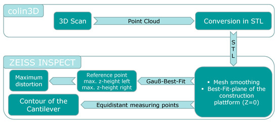
Figure 2.
Digital process chain for measurement of distortion.
First, the raw 3D scan data is cleaned to remove artifacts like powder adhesions. Then, a reference plane is established on the build platform using a Gaussian best-fit method. This plane serves as the baseline for all subsequent measurements. To visualize the cantilever’s contour, equidistant measurement points are used to create a measurement curve in the assembly direction. The maximum displacements of the cantilever are determined by applying a Gauss best-fit to specific measurement points. These points are generated on both the base body and the cantilever’s sides when viewed from above. Figure 3 illustrates these generated elements for distortion analysis and course representation.
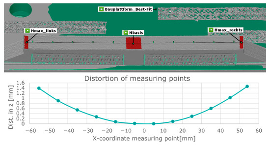
Figure 3.
Methodology of analyzing 3D-scanned dual cantilever specimen.
After analysis in ZEISS INSPECT software version 2025.3.1.6, the measurement results, specifically the maximum distortion and cantilever curves, are exported to a spreadsheet. This allows for easy viewing and comparison with other test results.
The relative density of the parameters utilized is determined by the fabrication of density cubes measuring 10 mm × 10 mm × 20 mm from the specified parameters and build jobs (Figure 4). After the construction stage, the full-volume bodies can be effectively separated, cut, embedded, and ground to facilitate density measurement in the subsequent step using a microscope.
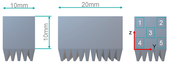
Figure 4.
Density cubes with the cutting zone and their measuring points under the microscope.
The density cubes are separated from the build platform, then further cut along their YZ-plane with an Abrasiment 2 separating machine (Buehler, ITW Test & Measurement GmbH, European Headquarters, Leinfelden-Echterdingen, Germany). The cut cubes are cold-embedded in their YZ-plane using VariKEM 200 (Schmitz Metallographie GmbH, Herzogenrath, Germany). Following embedding, the samples undergo a wet-grinding process through several grit levels (80 to 1200) and are finally polished with a 3 µm suspension using a Rotopol-22 machine (Struers GmbH, Willich, Germany).
For analysis, five bright-field images are taken of each sample at 50× magnification using an Olympus BX41M LED light microscope (Tokyo, Japan). On these grayscale images, defect-free material appears bright, while defects (like pores, cracks, and bonding defects) appear dark. This contrast allows for software-supported binarization using ImageJ (version 1.53k) to categorize material as either defect-free or defective. Finally, the average of the five measurement sections is calculated to determine the relative density, which is then used in conjunction with other examinations.
3. Experiments and Results
The selected parameters for the first measuring series are given in Table 1. They were chosen to present a base set-up that can be widely adapted, as they are mostly independent of the machine system used. The alternation between the layers was set for 67°, as previous experiments have shown that consistently or regularly overlapping scan vectors can have a high negative influence on RS and therefore falsify the experiments. For the reason of not interfering with the development of RS by other means, throughout this work, neither preheating nor postheat treatment was used. In order to vary the melt pool depth, the layer height was altered between a set-up of 30 µm and a set-up of 60 µm. To ensure that the scan tracks were fully melted and welded, it was necessary to adjust the energy input. In order to ensure that the process window was not exceeded, the volumetric energy density was maintained at a constant level. In addition, a meticulous density examination of all parameters was conducted to determine the presence of any potential deficiencies in fusion errors between the scan tracks or between the layers. The density threshold was set to 99.5% to avoid all systematic density errors arising from an exceeded process window. The width of the melt pool was modified by manipulating the spot diameter, which in turn necessitated an adjustment to the hatch spacing between the scan vectors. The present study concentrated on the significance of guaranteeing that the resulting VED remains consistent across all components when the parameters are varied. This approach is imperative for ensuring comparability of distortion results. It is also imperative to ensure that the parameter selection does not leave a suitable process window, particularly in terms of component density.

Table 1.
Parameter overview for the melt pool-size experiment (PL = laser power; Vs = scan speed; ds = hatch spacing; Ds = layer height; dspot = laser spot diameter; VED = volumetric energy density).
In completed build jobs, the influence of the selected parameters on the shape of the melt pool could be highlighted. In accordance with the state of the art, wider melt pools were formed as the spot diameter increased, and the same applies to the effect of the layer thickness on the melt pool depth. The following Figure 5 illustrates etched micrographs with varying dimensions of the melt pools. It is evident that the implementation of the designated scanning strategy (involving a 67° rotation of the scanning vectors in each layer) has resulted in the inability to measure the melting traces. However, the discernible trend remains identifiable.
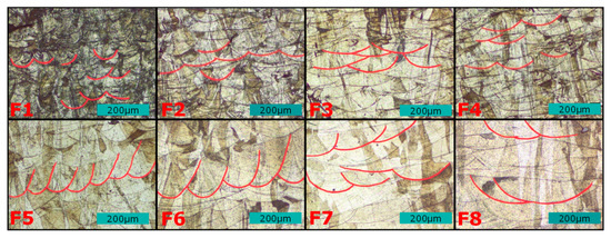
Figure 5.
Resulting melt pool geometries in dependence of spot diameter and layer thickness.
The layer thickness of 30 µm is displayed in the top row of micrographs, and the layer thickness of 60 µm is shown in the bottom row. The laser spot diameter used increases from left to right in the micrographs.
For each measuring point of the test series, a corresponding density cube is produced and analyzed. It is imperative that the usable process window is not overlooked. The subsequent graph illustrates the initial density results.
In the initial test series F, a wide variation in component density was observed. The accompanying diagram, Figure 6, illustrates these densities, showing that samples three and four (Ds = 30 µm, dspot = 180 µm and Ds = 30 µm, dspot = 230 µm, respectively) exhibited high porosity and failed to meet the minimum density requirement of 99.5%.
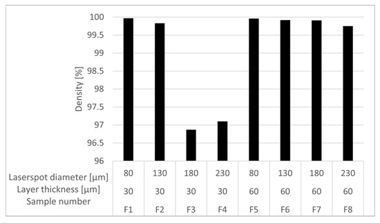
Figure 6.
First analysis of density results of varied parameters.
Consequently, a subsequent build job was initiated to facilitate a renewed analysis of the influence of the spot diameter. In this build job, the laser spot diameter was also varied at a layer thickness of 30 µm. However, a superior composition of laser power and scan speed was utilized to meet the density threshold. The parameters selected for test series FR are delineated in Table 2.

Table 2.
Revised parameters for the 30 µm layer height in order to meet the density threshold.
The following graph, Figure 7, illustrates the densities of the components from the additional build job (FR). It is evident that the component densities achieved undergo a slight decrease as the spot diameter increases. Apart from this tendency, sufficiently high component densities were achieved for all components.
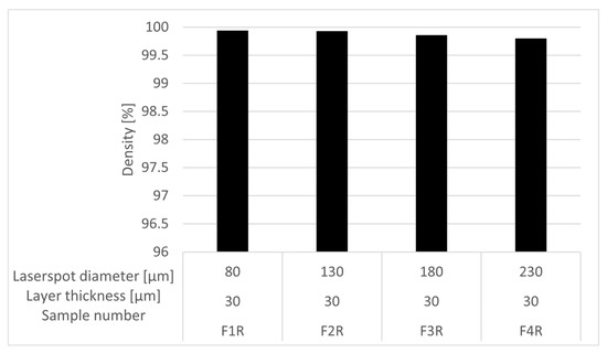
Figure 7.
Density measurement of test series FR with adjusted parameters.
Following the adjustment to the parameters, a set of parameters is now available for comparison that is fully comparable. This set of parameters allows for the isolation of layer height and track distance. In this context, it is imperative to acknowledge the significance of the archiving of dense specimens. This, in conjunction with the etched visualization of the weld tracks (e.g., Figure 5), provides evidence that the parameters produced either wider or deeper melt pools. It is therefore possible to utilize them for the purpose of investigating the premises.
The maximum cantilever distortions from test series F and test series FR are presented in Figure 8. Consistent with their previously noted lower component densities, samples F3 and F4 are hypothesized to exhibit substantially greater distortion if their densities are appropriately elevated. Sample F8 is expected to follow a similar pattern.
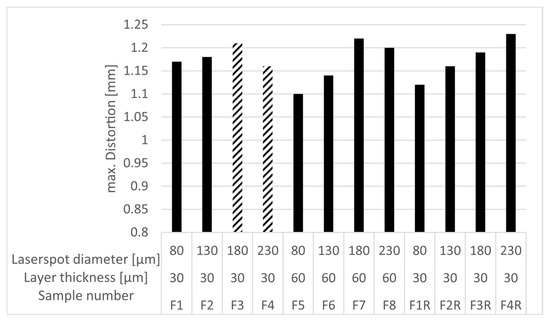
Figure 8.
Results for z-distortion of each measurement point of test series F and test series FR.
To illustrate the effect of layer height, Figure 8 shows a direct comparison of individual distortions for the same spot diameter on its left side. Increasing the layer height has a positive effect on the reduction in distortion. The comparison of the other spot diameters with regard to the influence of the layer thickness is not meaningful due to the different densities. Doubling the layer thickness from 30 µm to 60 µm results in a distortion reduction of approximately 6% at a spot diameter of 80 µm. The reduction here is the same as in the work of Kruth et al. [12]. At the larger spot diameter, this reduction is lower, at 3.4%.
In consideration of the posed research question, derived from the existing state of the art, it is imperative to distinguish the influence of either a wider melt pool or a deeper weld pool on the resulting residual stresses. The relevant parameters can therefore be isolated as follows.
The results of the direct comparison are given in Figure 9. They demonstrate that increasing the layer height contributes to reduced distortion. For instance, with an 80 µm spot diameter, a 6% reduction in distortion was observed when the layer thickness was doubled from 30 µm to 60 µm. This assertion is at least valid for most spot diameter sizes. In the case of the 180 µm spot diameter, the 60 µm specimen exhibited slightly more distortion than the 30 µm specimen. This is the sole measurement point that demonstrated this phenomenon. Concerning the spot diameter, a discernible tendency is evident. It is observed that an increase in both the spot diameter and consequently the hatch spacing results in a corresponding rise in the maximum distortion of the cantilever. By reducing the spot diameter from 230 µm to 80 µm, the distortion can be reduced by about 9%.
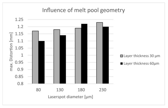
Figure 9.
Influence of melt pool geometry (layer thickness and spot diameter) on max. distortion.
4. Discussion
This paper presents a new method to investigate the influence of melt pool geometry on residual stresses by distortion measurements of cantilever parts. The main findings offer a new geometrical process parameter optimization method to reduce the residual stresses of the LPBF parts by increasing the layer thickness and decreasing the spot diameter, resulting in smaller deformations.
Despite the LPBF process being extensively utilized, and its capacity for application to numerous materials, its resulting internal stresses continue to present a significant challenge. This applies to materials that are susceptible to deformation and stress fractures, but also to standard materials such as 316L stainless steel. This is especially evident in scenarios where components are becoming increasingly larger in size, or when printed parts require further processing without incurring distortion through the utilization of additional heat-inducing processes such as welding. Consequently, researchers are perpetually investigating diverse methodologies for the reduction or avoidance of the residual stresses that are the consequence of this process. The present article provides a thorough overview of the state of the art in these process-inherent avoidance techniques. Another parameter that has not received much attention to date is examined in more detail and systematically here. The central question guiding this study is to ascertain the influence that a modified melt pool geometry exerts on the subsequent formation of residual stress.
In order to solve this question, dual cantilevers were built and analyzed using 3D scanning. The aim was to facilitate the drawing of conclusions regarding the resulting internal stresses, with these conclusions being based on the distortion that occurred. It is possible to make qualitative statements regarding the potential influence of a wider or deeper melt pool on internal stresses.
The results of the influence of layer thickness on process-related residual stresses are in line with the state-of-the-art investigations [12]. These also showed a reduction in residual stresses of 6% by doubling the layer height. From the agreement with the state of the art, it can be concluded that a deeper melt pool has a positive effect on the residual stresses. The assumption that an increased laser spot diameter would have a reducing effect on distortion in the LPBF could not be confirmed. The results obtained show an inverse relationship between the spot diameter and the level of residual stresses. The smaller the laser spot diameter, the lower the distortion. From this, it can be concluded that a larger focus diameter has a negative effect on the residual stresses in the process.
In order to provide a classification of the findings obtained in this study according to the current state of the art, it can be concluded that the increasing trend of cost-effectiveness and larger build volumes, in conjunction with greater layer thicknesses and larger track widths, has a negative effect on the resulting residual stresses in 316 L. When compared with all strategies for the avoidance of residual stress, the targeted adjustment of certain melt pool geometries is certainly not the most effective. It has been demonstrated that the reduction potential is approximately 6–9%, which is significantly lower than the efficiency of preheating. However, the description of this value is the missing piece in the complete description of LPBF parameters with the lowest possible residual stress. Consequently, in subsequent iterations of the process window design for processes with minimal residual stress, it is imperative to allocate consideration to the melt pool geometry and its concomitant deteriorating effects.
Author Contributions
Conceptualization, N.B. and S.B.; methodology, J.S.; software, J.S.; validation, F.E., N.B. and S.B.; formal analysis, F.E.; investigation, F.E.; resources, S.B. and N.B.; data curation, J.S.; writing—original draft preparation, F.E.; writing—review and editing, N.B., F.E. and S.B.; visualization, F.E.; supervision, F.E., N.B. and S.B.; All authors have read and agreed to the published version of the manuscript.
Funding
This research received no external funding.
Data Availability Statement
The original contributions presented in this study are included in the article. Further inquiries can be directed to the corresponding authors.
Conflicts of Interest
The authors declare no conflicts of interest.
References
- Płatek, P.; Sienkiewicz, J.; Janiszewski, J.; Jiang, F. Investigations on Mechanical Properties of Lattice Structures with Different Values of Relative Density Made from 316L by Selective Laser Melting (SLM). Materials 2020, 13, 2204. [Google Scholar] [CrossRef]
- Di Wang Song, C.; Yang, Y.; Bai, Y. Investigation of crystal growth mechanism during selective laser melting and mechanical property characterization of 316L stainless steel parts. Mater. Des. 2016, 100, 291–299. [Google Scholar] [CrossRef]
- Carpenter, K.; Tabei, A. On Residual Stress Development, Prevention, and Compensation in Metal Additive Manufacturing. Materials 2020, 13, 255. [Google Scholar] [CrossRef]
- Hooper, P.A. Melt pool temperature and cooling rates in laser powder bed fusion. Addit. Manuf. 2018, 22, 548–559. [Google Scholar] [CrossRef]
- Munsch, M. Reduzierung von Eigenspannungen und Verzug in der Laseradditiven Fertigung, 1st ed.; Lasertechnik, S., Ed.; Cuvillier Verlag: Göttingen, Germany, 2013. [Google Scholar]
- Risse, J. Additive Fertigung der Nickelbasis-Superlegierung IN738LC Mittels Selektivem Laserstrahlschmelzen. Ph.D. Thesis, RWTH Aachen University, Aachen, Germany, 2019. [Google Scholar]
- Klahn, C.; Meboldt, M.; Fontana, F.; Leutenecker-Twelsiek, B.; Jansen, J. (Eds.) Entwicklung und Konstruktion für die Additive Fertigung: Grundlagen und Methoden für den Einsatz in industriellen Endkundenprodukten. Ein Fachbuch von Konstruktionspraxis, 1st ed.; Vogel Business Media: Würzburg, Germany, 2018. [Google Scholar]
- Pichler, P.; Simonds, B.J.; Sowards, J.W.; Pottlacher, G. Measurements of thermophysical properties of solid and liquid NIST SRM 316L stainless steel. J. Mater. Sci. 2019, 55, 4081–4093. [Google Scholar] [CrossRef] [PubMed]
- Kaess, M.; Werz, M.; Weihe, S. Residual Stress Formation Mechanisms in Laser Powder Bed Fusion-A Numerical Evaluation. Materials 2023, 16, 2321. [Google Scholar] [CrossRef]
- Waqar, S.; Guo, K.; Sun, J. FEM analysis of thermal residual stress profile in selective laser melting of 316Lstainless steel. J. Manuf. Process. 2021, 66, 81–100. [Google Scholar] [CrossRef]
- Zhang, B.; Dembinski, L.; Coddet, C. The study of the laser parameters and environment variables effect on mechanical properties of high compact parts elaborated by selective laser melting 316L powder. Mater. Sci. Eng. A 2013, 584, 21–31. [Google Scholar] [CrossRef]
- Kruth, J.-P.; Deckers, J.; Yasa, E.; Wauthlé, R. Assessing and comparing influencing factors of residual stresses in selective laser melting using a novel analysis method. Proc. Inst. Mech. Eng. Part B J. Eng. Manuf. 2012, 226, 980–991. [Google Scholar] [CrossRef]
- Chao, Q.; Thomas, S.; Birbilis, N.; Cizek, P.; Hodgson, P.D.; Fabijanic, D. The effect of post-processing heat treatment on the microstructure, residual stress and mechanical properties of selective laser melted 316L stainless steel. Mater. Sci. Eng. A 2021, 821, 141611. [Google Scholar] [CrossRef]
- Cruz, V.; Chao, Q.; Birbilis, N.; Fabijanic, D.; Hodgson, P.; Thomas, S. Electrochemical studies on the effect of residual stress on the corrosion of 316L manufactured by selective laser melting. Corros. Sci. 2020, 164, 108314. [Google Scholar] [CrossRef]
- Sprengel, M.; Ulbricht, A.; Evans, A.; Kromm, A.; Sommer, K.; Werner, T.; Kelleher, J.; Bruno, G.; Kannengiesser, T. Towards the Optimization of Post-Laser Powder Bed Fusion Stress-Relieve Treatments of Stainless Steel 316L. Metall. Mater. Trans. A-Phys. Metall. Mater. Sci. 2021, 52, 5342–5356. [Google Scholar] [CrossRef]
- Williams, R.J.; Vecchiato, F.; Kelleher, J.; Wenman, M.R.; Hooper, P.A.; Davies, C.M. Effects of heat treatment on residual stresses in the laser powder bed fusion of 316L stainless steel: Finite element predictions and neutron diffraction measurements. J. Manuf. Process. 2020, 57, 641–653. [Google Scholar] [CrossRef]
- Tascioglu, E.; Karabulut, Y.; Kaynak, Y. Influence of heat treatment temperature on the microstructural, mechanical, and wear behavior of 316L stainless steel fabricated by laser powder bed additive manufacturing. Int. J. Adv. Manuf. Technol. 2020, 107, 1947–1956. [Google Scholar] [CrossRef]
- Liu, Y.; Yang, Y.; Wang, D. A study on the residual stress during selective laser melting (SLM) of metallic powder. Int. J. Adv. Manuf. Technol. 2016, 87, 647–656. [Google Scholar] [CrossRef]
- Yakout, M.; Elbestawi, M.A.; Veldhuis, S.C. Density and mechanical properties in selective laser melting of Invar 36 and stainless steel 316L. J. Mater. Process. Technol. 2019, 266, 397–420. [Google Scholar] [CrossRef]
- Jagatheeshkumar, S.; Raguraman, M.; Siva Prasad, A.V.S.; Nagesha, B.K.; Chandrasekhar, U. Study of residual stresses and distortions from the Ti6Al4V based thin-walled geometries built using LPBF process. Def. Technol. 2023, 28, 33–41. [Google Scholar]
- Wu, A.S.; Brown, D.W.; Kumar, M.; Gallegos, G.F.; King, W.E. An Experimental Investigation into Additive Manufacturing-Induced Residual Stresses in 316L Stainless Steel. Metall. Mater. Trans. A-Phys. Metall. Mater. Sci. 2014, 45, 6260–6270. [Google Scholar] [CrossRef]
- Simson, T.; Emmel, A.; Dwars, A.; Böhm, J. Residual stress measurements on AISI 316L samples manufactured by selective laser melting. Addit. Manuf. 2017, 17, 183–189. [Google Scholar] [CrossRef]
- Greco, S.; Gutzeit, K.; Hotz, H.; Kirsch, B.; Aurich, J.C. Selective laser melting (SLM) of AISI 316L—Impact of laser power, layer thickness, and hatch spacing on roughness, density, and microhardness at constant input energy density. Int. J. Adv. Manuf. Technol. 2020, 108, 1551–1562. [Google Scholar] [CrossRef]
- Mugwagwa, L.; Dimitrov, D.; Matope, S.; Yadroitsev, I. Influence of process parameters on residual stress related distortions in selective laser melting. Procedia Manuf. 2018, 21, 92–99. [Google Scholar] [CrossRef]
- Ali, H.; Ghadbeigi, H.; Mumtaz, K. Processing Parameter Effects on Residual Stress and Mechanical Properties of Selective Laser Melted Ti6Al4V. J. Mater. Eng Perform 2018, 27, 4059–4068. [Google Scholar] [CrossRef]
- Ilie, A.; Ali, H.; Mumtaz, K. In-Built Customised Mechanical Failure of 316L Components Fabricated Using Selective Laser Melting. Technologies 2017, 5, 9. [Google Scholar] [CrossRef]
- Xiao, Z.; Chen, C.; Zhu, H.; Hu, Z.; Nagarajan, B.; Guo, L.; Zeng, X. Study of residual stress in selective laser melting of Ti6Al4V. Mater. Des. 2020, 193, 108846. [Google Scholar] [CrossRef]
- Bian, P.; Shi, J.; Liu, Y.; Xie, Y. Influence of laser power and scanning strategy on residual stress distribution in additively manufactured 316L steel. Opt. Laser Technol. 2020, 132, 106477. [Google Scholar] [CrossRef]
- Robinson, J.; Ashton, I.; Fox, P.; Jones, E.; Sutcliffe, C. Determination of the effect of scan strategy on residual stress in laser powder bed fusion additive manufacturing. Addit. Manuf. 2018, 23, 13–24. [Google Scholar] [CrossRef]
- Robinson, J.H.; Ashton, I.R.T.; Jones, E.; Fox, P.; Sutcliffe, C. The effect of hatch angle rotation on parts manufactured using selective laser melting. Rapid Prototyp. J. 2019, 25, 289–298. [Google Scholar] [CrossRef]
- Zaeh, M.F.; Branner, G. Investigations on residual stresses and deformations in selective laser melting. Prod. Eng. Res. Devel. 2010, 4, 35–45. [Google Scholar] [CrossRef]
- Lu, Y.; Wu, S.; Gan, Y.; Huang, T.; Yang, C.; Junjie, L.; Lin, J. Study on the microstructure, mechanical property and residual stress of SLM Inconel-718 alloy manufactured by differing island scanning strategy. Opt. Laser Technol. 2015, 75, 197–206. [Google Scholar] [CrossRef]
- Hajnys, J.; Pagáč, M.; Měsíček, J.; Petru, J.; Król, M. Influence of Scanning Strategy Parameters on Residual Stress in the SLM Process According to the Bridge Curvature Method for AISI 316L Stainless Steel. Materials 2020, 13, 1659. [Google Scholar] [CrossRef]
- Mercelis, P.; Kruth, J.-P. Residual stresses in selective laser sintering and selective laser melting. Rapid Prototyp. J. 2006, 12, 254–265. [Google Scholar] [CrossRef]
- Anderson, L.S.; Venter, A.M.; Vrancken, B.; Marais, D.; Van Humbeeck, J.; Becker, T.H. Investigating the Residual Stress Distribution in Selective Laser Melting Produced Ti-6Al-4V Using Neutron Diffraction. In Mechanical Stress Evaluation by Neutron and Synchrotron Radiation; Materials Research Proceedings; Materials Research Forum LLC: Millersville, PA, USA, 2018; pp. 73–78. [Google Scholar]
- Larimian, T.; AlMangour, B.; Grzesiak, D.; Walunj, G.; Borkar, T. Effect of Laser Spot Size, Scanning Strategy, Scanning Speed, and Laser Power on Microstructure and Mechanical Behavior of 316L Stainless Steel Fabricated via Selective Laser Melting. J. Mater. Eng. Perform. 2022, 31, 2205–2224. [Google Scholar] [CrossRef]
- Yang, X.-H.; Jiang, C.-M.; Ho, J.-R.; Tung, P.-C.; Lin, C.-K. Effects of Laser Spot Size on the Mechanical Properties of AISI 420 Stainless Steel Fabricated by Selective Laser Melting. Materials 2021, 14, 4593. [Google Scholar] [CrossRef]
- Weaver, J.S.; Heigel, J.C.; Lane, B.M. Laser spot size and scaling laws for laser beam additive manufacturing. J. Mater. Process Technol. 2022, 73, 26–39. [Google Scholar] [CrossRef] [PubMed]
- Buchbinder, D.; Schilling, G.; Meiners, W.; Pirch, N.; Wissenbach, K. Untersuchung zur Reduzierung des Verzugs durch Vorwärmung bei der Herstellung von Aluminiumbauteilen mittels SLM. Rte J. 2011, 8. Available online: https://rtejournal.de/rte/article/view/2011_1/181 (accessed on 7 September 2025).
Disclaimer/Publisher’s Note: The statements, opinions and data contained in all publications are solely those of the individual author(s) and contributor(s) and not of MDPI and/or the editor(s). MDPI and/or the editor(s) disclaim responsibility for any injury to people or property resulting from any ideas, methods, instructions or products referred to in the content. |
© 2025 by the authors. Licensee MDPI, Basel, Switzerland. This article is an open access article distributed under the terms and conditions of the Creative Commons Attribution (CC BY) license (https://creativecommons.org/licenses/by/4.0/).