Article

An Experimental Study on Tensile Characteristics of Ti-6Al-4V Thin Struts Made by Laser Powder-Bed Fusion: Effects of Strut Geometry and Linear Energy Density

Department of Industrial Engineering, Speed School of Engineering, University of Louisville, Louisville, KY 40292, USA
*
Author to whom correspondence should be addressed.
Current address: Electronics and Automation Department, Technical Sciences Vocational Schools, Bayburt University, Bayburt 69100, Turkey.
Metals 2025, 15(9), 1009; https://doi.org/10.3390/met15091009
Submission received: 17 July 2025 / Revised: 27 August 2025 / Accepted: 4 September 2025 / Published: 11 September 2025

Abstract

Laser powder bed fusion (L-PBF) enables the fabrication of complex lattice-type structures composed of thin struts, offering lightweight, high-strength advantages in aerospace and biomedical applications, among others. While extensive research has examined full lattices and process parameter effects individually, the combined influence of strut geometry, configuration, and processing conditions on mechanical properties remains less understood. This study investigates how the strut number, strut size, cross-sectional shape, and laser energy input affect the mechanical properties of thin-strut L-PBF tensile specimens. Ti-6Al-4V struts were designed and fabricated using an EOS M270 system using five linear energy density (LED) levels. The fabricated specimens were measured in porosity using micro-scaled computed tomography and further evaluated using a tensile tester. The results showed that increasing the strut number leads to significant reductions in tensile strength, even with the same overall cross-sectional area, especially at low LED levels. Size effects on mechanical strengths were observed, though mostly minimal, except at the smallest strut size, where defects tend to be more critical. Circular and square shapes performed similarly under general LED conditions; however, square struts exhibited inferior behavior at the lowest LED level. Overall, LED is the most influential factor, with the greatest tensile strength occurring near 0.2 J/mm; further decreasing or increasing the LED both increase the porosity, degrading mechanical strengths.

1. Introduction

Additive manufacturing (AM) is a process of joining materials to create objects from 3D model data, usually layer by layer, as opposed to subtractive manufacturing, where material is removed to form the desired shape [1]. Laser powder bed fusion (L-PBF), a prominent AM technique, utilizes a high-energy laser to selectively fuse metal or alloy powders layer by layer. This process is especially useful for producing complex metal parts due to its design flexibility, reduced material waste, and shortened production cycles. L-PBF’s ability to produce high-density parts with intricate geometries and superior mechanical properties has propelled its adoption in aerospace, medical, and automotive sectors [2].
L-PBF enables the production of complex lattice architectures composed of thin struts and nodes that optimize material usage and performance. L-PBF is more accurate and suitable for lattice structure fabrication compared to alternative AM methods such as laser engineering net shaping (LENS) [3]. These structures are currently driving advancements in areas such as biomedical implants and lightweight components for the aerospace industry [4,5,6]. Ti-6Al-4V is among the most common alloys used in L-PBF, especially within the aerospace sector. This alloy accounts for the majority of titanium consumption, and AM is utilized to minimize machining expenses and material waste given the high cost of titanium and its machining processes [7,8,9].
Most existing studies focus on manufacturability and mechanical evaluation of complete lattice structures [10,11,12,13]. At the micro scale, however, the mechanical performance of lattice structures is strongly influenced by the geometry and orientation of their individual struts [14]. Understanding the tensile response of these small features under load is crucial for predicting and enhancing the overall performance of AM parts. Previous studies have shown that factors such as strut geometry, build orientation, and process parameters can significantly affect the mechanical properties of these features [15,16]. Despite extensive research in this field, there is still a lack of an integrated understanding of how strut geometry (e.g., diameter and shape), configurations (e.g., single vs. multi-strut), and process parameters jointly affect mechanical properties.
The influence of build orientation on the mechanical properties of L-PBF fabricated Ti-6Al-4V has been well documented. For example, Murchio et al. [17] examined the tensile strength and fatigue behavior of thin Ti-6Al-4V lattice struts fabricated by L-PBF across different build orientations (0°, 15°, 45°, and 90°). They specifically focused on how microstructural defects like porosity and variations in surface geometry affect mechanical performance. They found a decrease in fatigue life with lower build angles, attributed to increased surface roughness and irregular cross-sectional geometry. However, monotonic tensile tests showed comparatively lower sensitivity to these geometric and surface features. Hossain et al. [18] compared how build angle affects the tensile behavior of SS316L and Ti-6Al-4V. They reported that while the elastic modulus of both SS316L and Ti-6Al-4V materials, as well as the strength of SS316L, remained unaffected by build angle, the strength of Ti-6Al-4V was significantly influenced by build angle, more than doubling when the strut was built at 90° compared to 20°. For both alloys, increased build angles reduced surface roughness and improved cross-sectional circularity, with this effect being more pronounced in Ti-6Al-4V. These studies, among others, demonstrate that vertically fabricated struts consistently outperform those built at lower angles.
In a separate study, Dressler et al. [15] found that multi-strut specimens made of stainless steel 17-4PH showed lower average tensile strength and higher variability than large monolithic tensile bars. Notably, some struts exhibited tensile strengths as low as ~400 MPa, compared to 930 MPa of large monolithic bars, posing serious concerns for lattice integrity due to the risk of failure propagation through weak links. However, they did not explore the difference between multi- and single-strut specimens, focusing solely on five-strut specimens. Similarly, Bültmann et al. [19] only compared multi-strut specimens using 19-, 28-, and 37-strut specimens to observe the effect of strut number. However, they did not report any significant variation in tensile strength, and the study used stainless steel 316L powder. These findings highlight the need to expand such investigations to Ti-6Al-4V and compare single vs. multi-strut configurations, varying sizes, and shapes across different process parameters.
X-ray computed tomography (XCT) has been widely used as a non-destructive method to characterize porosity in L-PBF parts. It provides high-resolution 3D imaging for assessing internal structures and detecting sub-surface defects [20,21]. Compared to optical microscopy, XCT is less prone to selection bias as it accounts for the full volume, and it has also been shown to be more cost-effective and accurate [22]. Voisin et al. [23] used XCT to identify coalescence and growth of pores as key failure mechanisms when the tensile axis is perpendicular to the build direction, resulting in reduced tensile strain to failure. These failure mechanisms were not observed when the tensile axis was aligned parallel to the build direction.
The significant influence of process parameter-induced porosity on the mechanical properties of L-PBF fabricated Ti-6Al-4V has been well documented. Kan et al. [24] examined how porosity influences the tensile and toughness properties of L-PBF Ti-6Al-4V, with the goal of balancing build speed and mechanical performance. They observed that at near-zero porosity, strength variations stem from microstructural differences alone. However, specimens with higher porosity, particularly those containing irregular lack of fusion (LoF) pores, consistently showed significantly reduced mechanical properties than those with spherical pores. Joshi et al. [25] conducted both experimental and computational analysis on Ti-6Al-4V fabricated by L-PBF to assess how porosity influences mechanical properties. They found that higher laser scan speeds led to more lack-of-fusion defects, which in turn reduced both yield strength and strain to failure. At higher porosity levels, the variability in strain to failure decreased across specimens. The computational model, which used a two-scale approach for processing and deformation-induced pores, aligned well with experimental trends. However, it underestimated improvements in yield strength at low porosity, likely due to simplifications that excluded microstructural effects. Collectively, these studies clearly demonstrate that process parameters significantly govern porosity formation, which in turn critically affects the tensile properties of L-PBF Ti-6Al-4V components. However, most of these studies primarily focus on porosity or process conditions in isolation. They do not systematically investigate how process parameters interact with strut geometry (e.g., diameter and shape) and configuration (e.g., single vs. multi-strut assemblies) to influence mechanical performance.
Therefore, the present study addresses an important research gap: how geometry, configuration, and processing parameters jointly affect the mechanical behavior of thin struts. This is achieved by fabricating tensile coupons with circular and square cross-sections, each designed with varying numbers of struts (one, two, four, and nine) to systematically evaluate these influences. Struts were built in vertical orientation only, as Ti-6Al-4V is known to exhibit weaker mechanical properties in horizontal or sloped build directions [15,17,18]. The cross-sectional area was standardized at 2.55 mm2, with a gauge length of 4 mm. Specimens were fabricated on an EOS M270 system using Ti-6Al-4V powder across five linear energy density (LED) levels and tested to assess the combined effects of geometry, configuration, and processing parameters on mechanical properties. Micro-CT scans were utilized to investigate the effects of process-induced porosity on tensile strength. In addition, tensile tests were carried out on an ADMET system to acquire stress–strain data for mechanical property analysis.

2. Materials and Methods

2.1. Specimen Design

Miniature tensile coupons were fabricated with varying numbers of struts. The corresponding dimensions and strut counts are detailed in Table 1. To allow for a direct comparison of mechanical performance, all designs maintained a constant total cross-sectional area of approximately 2.55 mm2. Table 2 shows the specimen design plan used to study the effect of strut number. Additionally, single-strut specimens were fabricated to match the dimensions of individual struts from each multi-strut design. This approach allowed the isolation of the strut size effect and enabled the comparison of mechanical behavior between single and multi-strut configurations, as shown in Table 3. All specimens feature a gauge length of 4 mm, but a 10 mm gauge extensometer was employed to minimize unwanted stress concentration in the gauge area. To secure the extensometer blades, special notches were incorporated into the specimens that ensured stable positioning during testing. Finally, as illustrated in Figure 1, overall specimen dimensions were approximately 50% of the smallest ASTM E8 flat specimen.

2.2. Fabrication Process

Specimens were fabricated using an EOS M270 (EOS GmbH, Munich, Germany) with Ti-6Al-4V powder from Carpenter Technology Corporation (Philadelphia, PA, USA) with a particle size distribution of 15–45 µm. The layer thickness was set to 30 µm, and a 0–90º alternating raster pattern was employed with a hatch spacing of 100 µm. Laser energy input is commonly quantified by volumetric energy density (VED), calculated as shown in Equation (1), where P ,   v , h , a n d   t refer to laser power, scan speed, hatch spacing, and layer thickness, respectively. Since in this study, the hatch spacing and the layer thickness were kept constant, a modified metric called linear energy density (LED) was employed, as illustrated in Equation (2). The laser used during fabrication had a beam diameter of 100 µm. Post-contouring was applied to improve surface finish and dimensional accuracy, with 150 W power and a scan speed of 1250 mm/s. To investigate the effect of process parameters on mechanical properties, specimens were fabricated using five different LEDs. Table 4 presents the utilized process parameters along with the corresponding LED in J/mm.
VED = P v h t
LED = P v
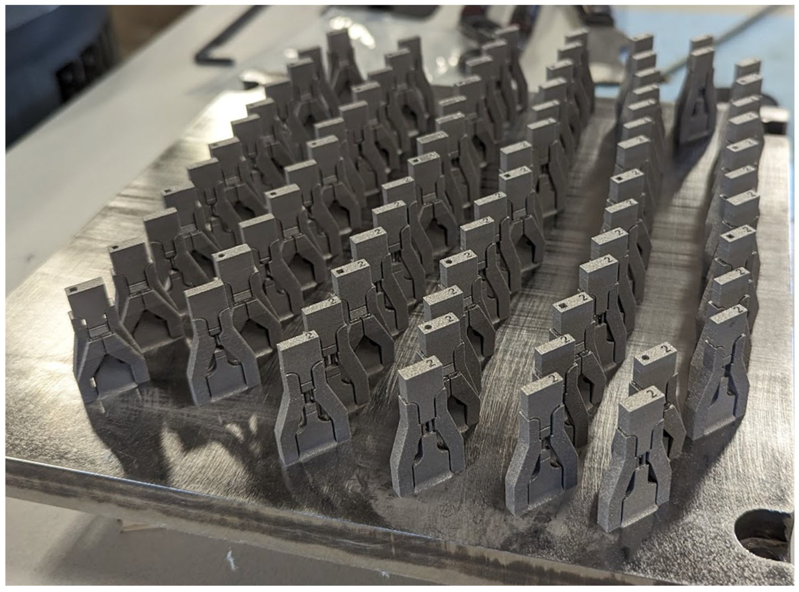
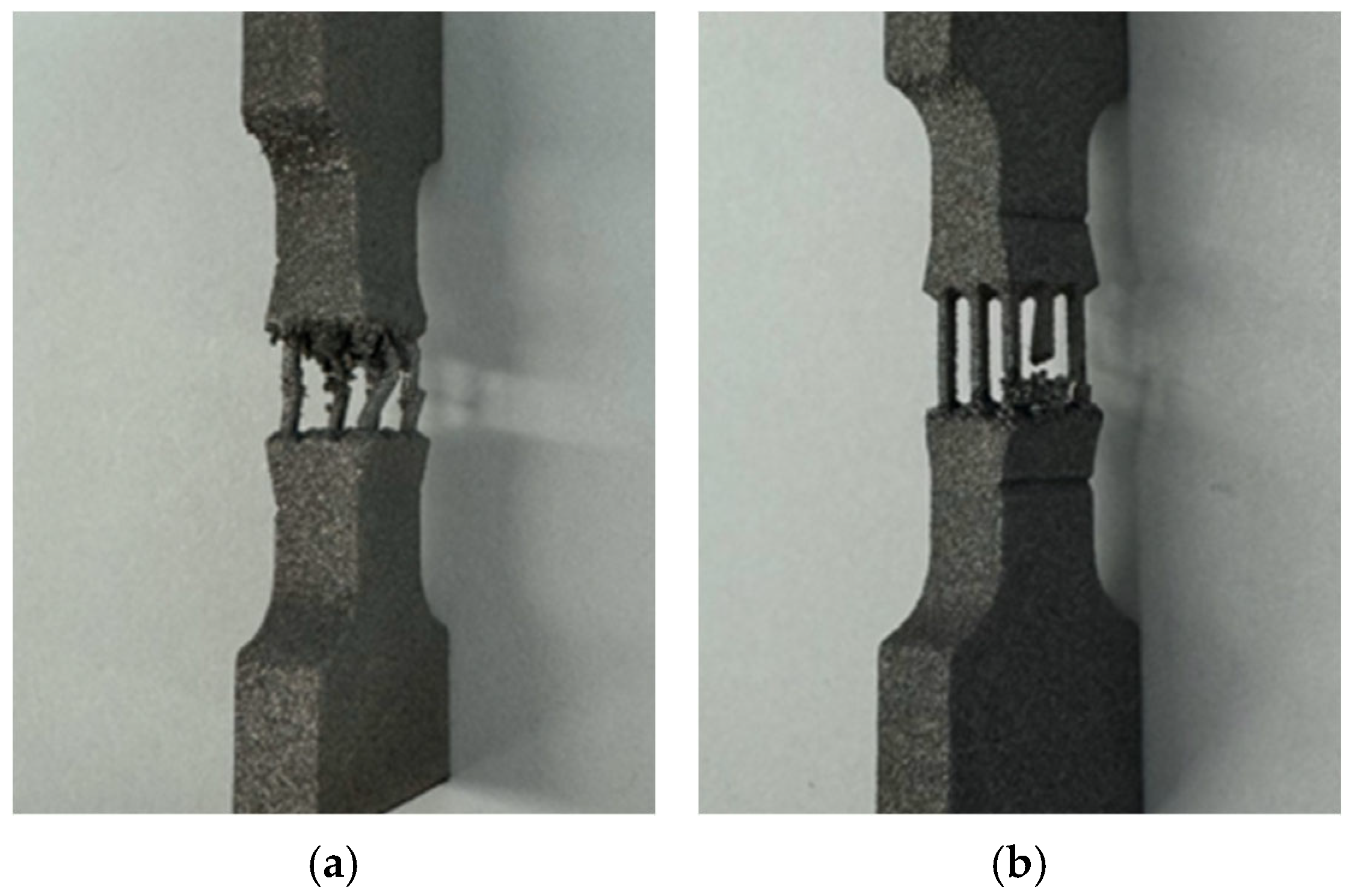
Specimen designs containing single and multi-strut configurations, as shown in Table 2, were built across these five LEDs to study the combined effect of strut number and energy input. However, the specimens presented in Table 3 were only built at LED#3 (EOS recommended setting). As a result, the size effect was studied in isolation, but it reduced the number of specimens to be tested. Specimens were fabricated on a titanium base plate as shown in Figure 2. Following fabrication, an electrical discharge machine (EDM) was used to remove the specimens from the base plate. The supports were manually removed after EDM. Figure 3 demonstrates finished tensile specimens. However, the 9-strut specimens of LED#1 and LED#5 were structurally defective, as shown in Figure 4. For these specimens, the struts were the thinnest and the LED levels were extreme, making the fabrication process challenging. Additionally, the proximity of the struts contributed significantly to the failure, as this created further complications during the fabrication process.

2.3. Tensile Testing

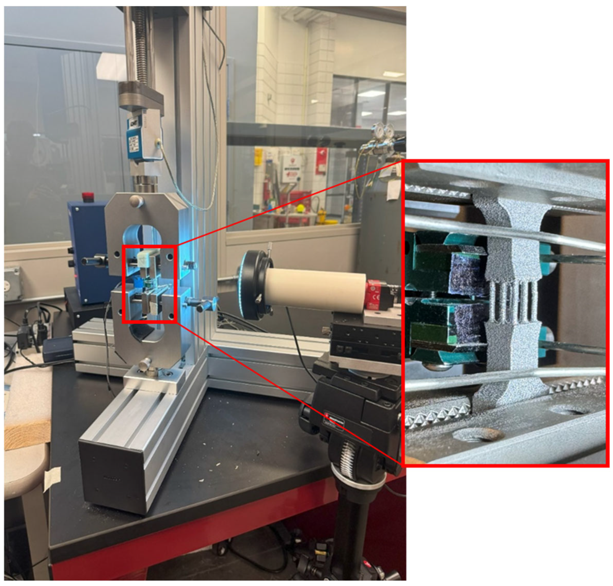
The fabricated specimens were measured for dimensional deviation from nominal values using a digital caliper with a precision of 0.01 mm. Subsequently, tensile testing was conducted on at least three replicates for each specimen design. The testing apparatus consisted of an ADMET tensile tester (eXpert 5600, ADMET Inc., Norwood, MA, USA) interfaced with MTEST Quattro software (version 6.02.10) from the same company. Prior to each test, the orientation of the specimens was verified and maintained in a vertical position using a dial indicator. The tests were performed at a strain rate of 0.005 s−1 using a 4.4 kN load cell from ADMET. An Epsilon axial extensometer (Model 3442, Epsilon Tech. Corp., Jackson, WY, USA) with a 10 mm gauge length and a 3 mm travel range was utilized to obtain strain data, as highlighted in Figure 5. Key mechanical properties such as ultimate tensile strength (Sut) and Young’s modulus (E) were obtained and recorded using the MTEST Quattro software.

2.4. Micro-CT Scan

Specimens were scanned using a Bruker Skyscan 1173 (Billerica, MA, USA) micro-scaled computed tomography (micro-CT) scanner. The voltage of the X-ray was set at 130 kV and the pixel size at 7.1 µm. To mitigate beam hardening artifacts, a 0.25 mm brass filter was employed. Scanning was performed with a 0.2-degree rotation step for a full 360-degree scan. NRECON software (Version: 1.7.1.0, Bruker, Billerica, MA, USA) was used for reconstruction. Gray-scale images were acquired using standard reconstruction procedures [26,27]. Beam hardness correction, smoothing, and misalignment compensation were achieved by fine-tuning the parameters to reduce ring artifacts, blurring effects, and other imaging issues. Moreover, CT-Analyzer (CTAN) (by Bruker) was utilized for quantitative analysis, including porosity percentage, average pore volume, and other related metrics. The gauge section of the specimens was selected as the volume of interest with a height of 4 mm.

3. Results and Discussion

3.1. Strut Geometry Effect

The geometry of load-bearing struts in cellular and lattice structures plays a critical role in determining their mechanical response, particularly under uniaxial tension [28]. Geometrical features such as strut size and shape strongly influence the distribution of energy input and cooling rates during the L-PBF process, which in turn affects local microstructural evolution and ultimately the mechanical strength of the part [29]. Strut design factors such as number, cross-sectional size, and shape dictate effective load transfer paths and stress concentrations within the lattice.
This section investigates how variations in strut number, size, and shape influence the tensile response of L-PBF Ti-6Al-4V thin-strut specimens. The key responses are mechanical behavior, including stress–strain plots and tensile properties (Sut and E). In addition, the porosity characteristics were investigated to provide a more comprehensive understanding of how geometry influences mechanical performance.

3.1.1. Strut Number Effect

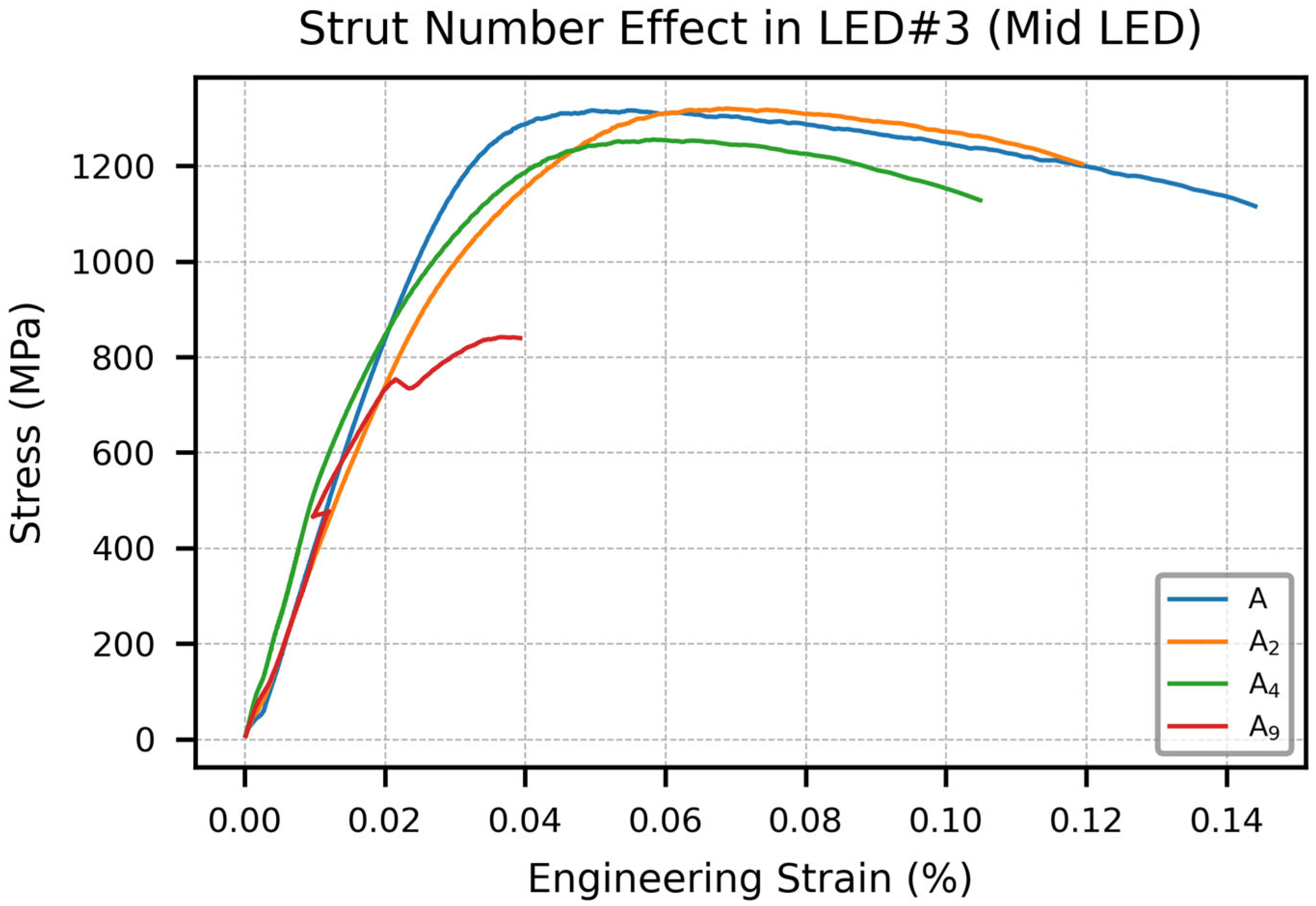
The representative stress–strain curves for different strut configurations (A, A2, A4, and A9) fabricated at a mid-range linear energy density (LED#3) are shown in Figure 6. The mechanical response exhibits a clear downward trend in strength and ductility as the strut count increases. All specimens showed an initial linear elastic region, followed by strain hardening and eventual failure. The single-strut specimen (A) achieved the highest Sut exceeding 1300 MPa and maintained ductility up to approximately 15% strain. The A2 and A4 specimens displayed similar E values but a slightly reduced Sut and ductility. Notably, the A9 specimen representing the highest strut count exhibited significantly lower tensile strength (~850 MPa) with struts failing earlier than the ultimate failure of the whole configuration. The stress–strain curve for the A9 specimen in Figure 6 shows a sudden jump due to the early failure of some struts shaking the test apparatus. This is likely driven by defect accumulation and stress concentrations arising from closely spaced struts.
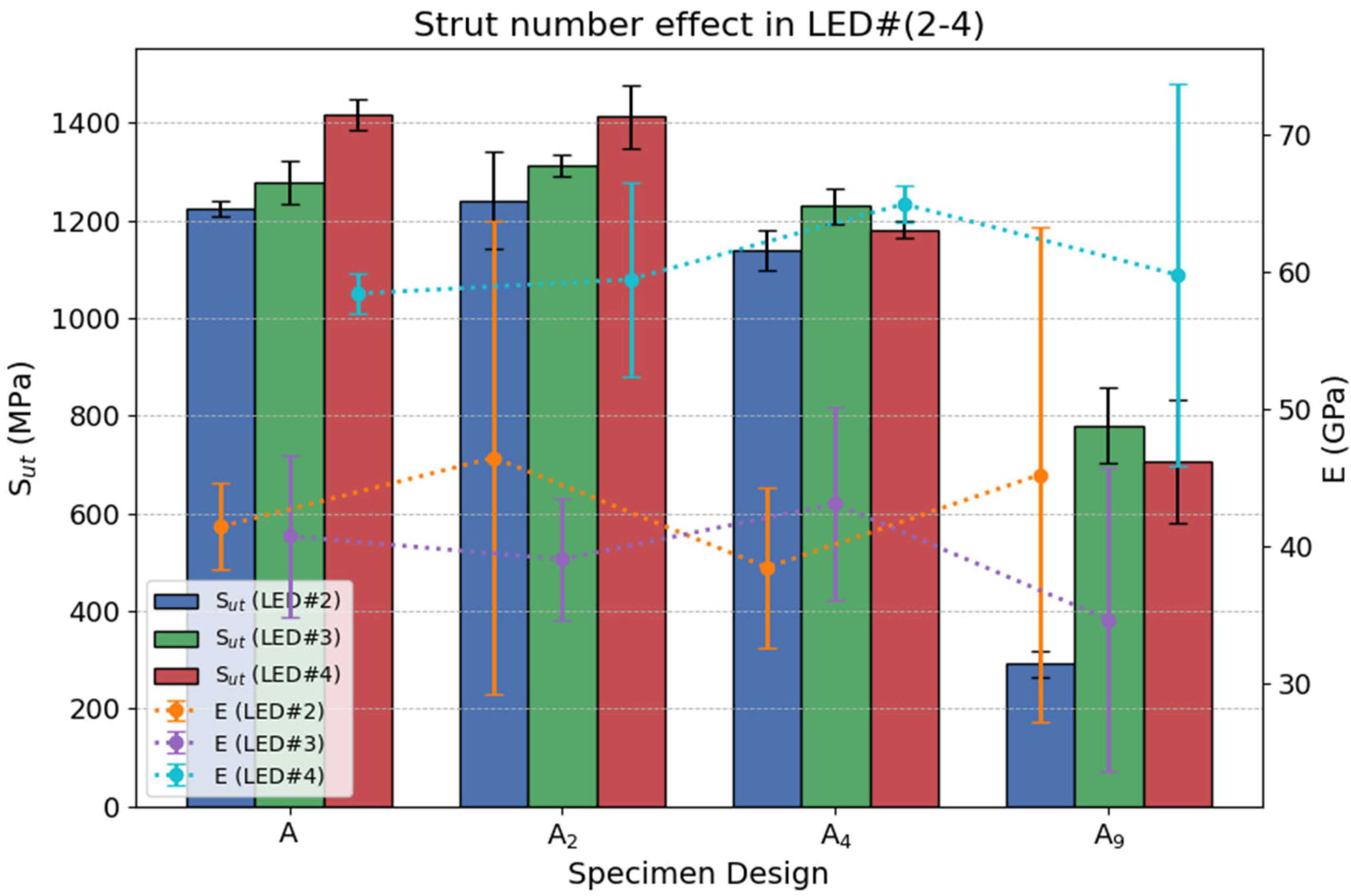
Tensile property comparisons across LED#2–4 are summarized in Figure 7. Since A9 specimens failed fabrication under LED#1 and LED#5, as depicted in Figure 4, these energy levels were excluded from the comparison in Figure 7. Across all LED levels in Figure 7, it can be seen that Sut decreased with an increasing strut count, with A9 consistently exhibiting the lowest performance across all energy inputs. Specimens A and A2 showed comparable Sut values (~1250–1450 MPa), whereas A4 demonstrated a moderate reduction (~1200 MPa). The observed E range (40–60) GPa is very low compared to typical E (100–110) GPa for standard ASTM-sized specimens, as reported in the literature. This deviation, consistent with the findings of Murchio et al. [17] and Hossain et al. [18], can be attributed to the amplified effects of surface roughness, porosity, and geometric inaccuracies at reduced scales. The E values did not exhibit a consistent trend across all LEDs. However, specimens fabricated with LED#4 consistently exhibited higher stiffness compared to those produced with LED#2 and LED#3. The error bars in both Sut and E further highlight the increasing variability with higher strut counts.
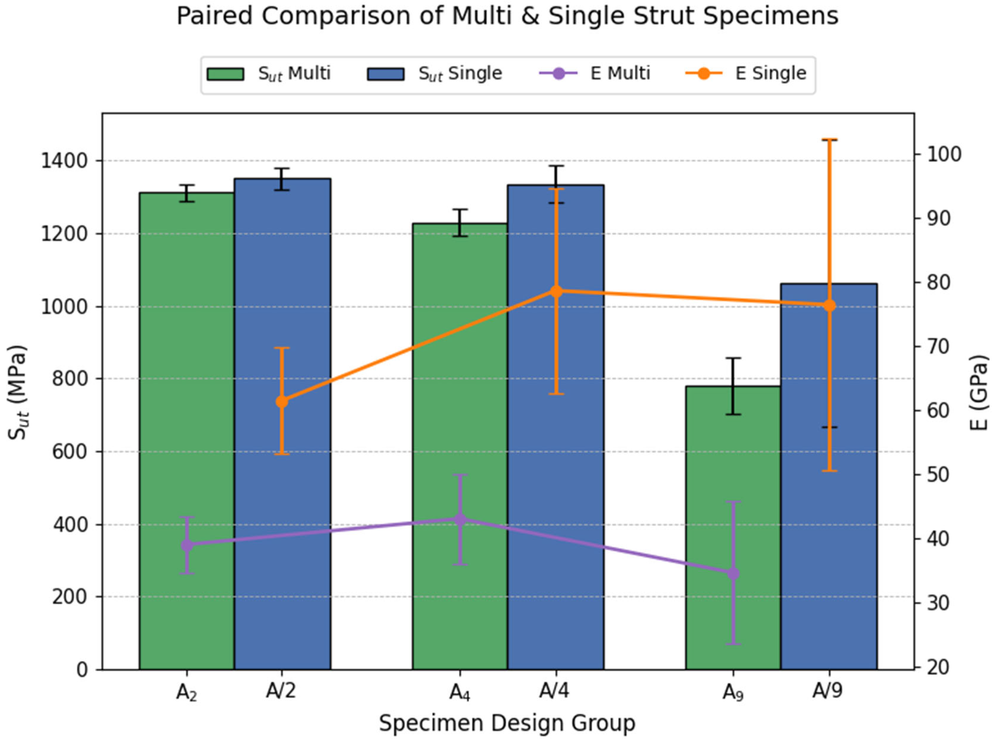
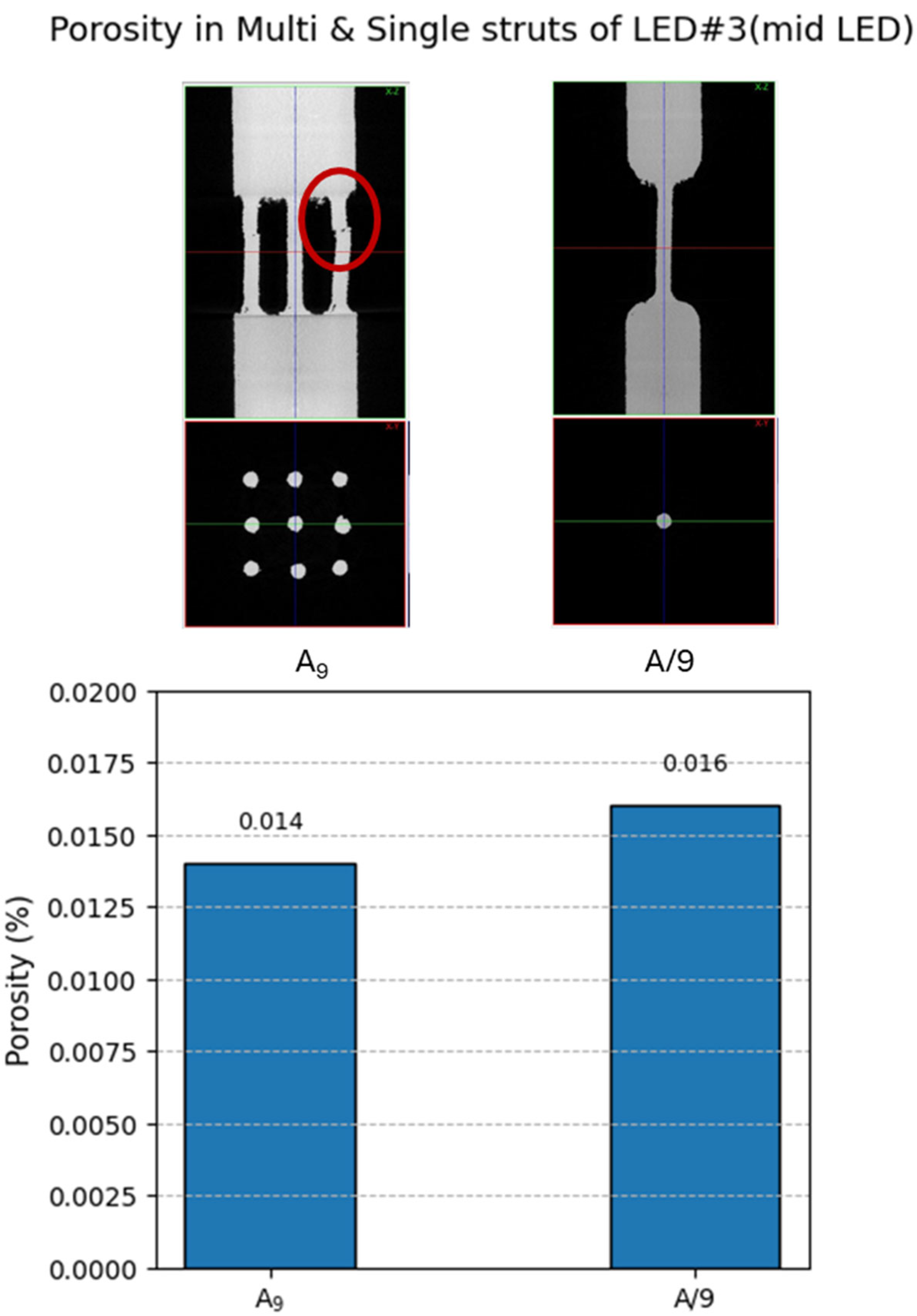
A direct comparison between multi-strut and single-strut specimens is shown in Figure 8. (See Table 2 and Table 3 for visual reference.) Notably, in all cases (e.g., A2 vs. A/2, A4 vs. A/4, and A9 vs. A/9), the single-strut specimens demonstrate consistently higher Sut and E values than their multi-strut counterparts. This finding reveals that having multiple small struts together does not maintain similar mechanical performance. For instance, the nine-strut specimen (A9) shows a 30–60% reduction in tensile strength compared to A/9. This discrepancy is attributed to the increased number of potential failure sites introduced by multi-strut configurations. For example, the strut marked as red in Figure 9 has a fabrication defect and failed first under tensile load. Such early failing struts contribute negligibly to load-bearing but are still included in the nominal cross-sectional area used for strength calculations. Therefore, the mechanical inefficiency of multi-strut geometries stems from their susceptibility to local defects and uneven load distribution, ultimately leading to reduced effective performance despite increased material volume.
It is well established that the microstructure strongly influences the mechanical properties of L-PBF parts due to, e.g., the difference in α′/α lath thickness [30]. However, a prior study has shown that within the 0.5–1.5 mm size range, the variation in α′/α lath thickness is minimal, typically within ~0.1 µm [31]. Similarly, Zhao et al. [32] and Promoppatum et al. [33] reported that strut size has little influence on the microstructure of L-PBF Ti-6Al-4V, with lath thicknesses remaining in a narrow range. Therefore, within the present strut size range (0.6–1.8 mm), microstructural variations are not expected to significantly influence the mechanical properties.
To further establish the effect of strut configuration, Figure 9 compares the porosity of A9 and A/9 specimens, both of which share identical strut diameters and were fabricated under the same process parameters (LED#3). The results reveal no significant difference in porosity between the two configurations (0.014% for A9 vs. 0.016% for A/9), indicating that porosity is independent of strut count when strut size and processing parameters are kept constant. Despite this similarity in porosity content, the A/9 specimen exhibits substantially higher tensile strength and stiffness, as shown in Figure 8. This confirms that the inferior performance of the multi-strut configuration arises from geometric and structural inefficiencies, such as the fabrication defects marked in red in Figure 9, and early failure of individual struts rather than from differences in porosity.

3.1.2. Strut Size Effect

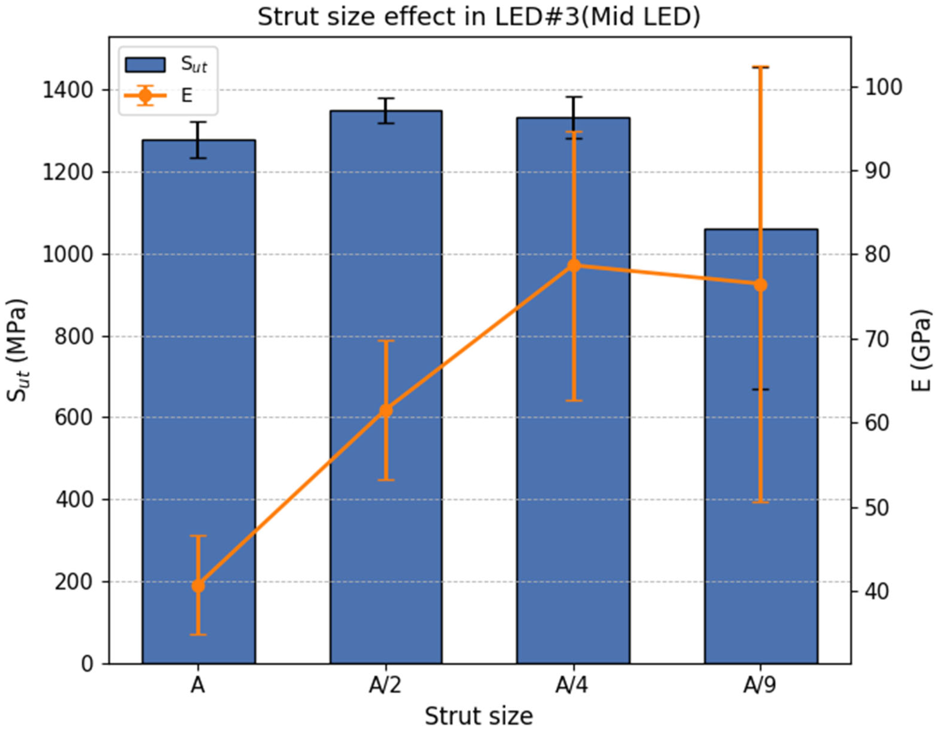
The single-strut specimens illustrated in Table 3 were designed to isolate the effect of strut size on tensile properties. However, to reduce the number of tensile tests, these specimens were only built at LED#3, which is close to the machine recommended EOS 270 parameters. The results are presented in Figure 10, showing the Sut and E values for each specimen. As illustrated, the tensile strength remains relatively stable across most sizes, indicating minimal dependence on strut size. In contrast, the smallest specimen (A/9) exhibits a noticeable drop in average strength, along with high variability in both strength and modulus, suggesting increased process sensitivity or defect influence at this scale. Bültmann et al. [19] in a similar scenario hypothesized that inhomogeneities on smaller struts have a greater chance of leading to earlier necking compared to larger struts.
Multi-strut specimens were used to study the effect of strut size on porosity. Figure 11 shows cross-sectional CT scans and quantitative porosity measurements for specimens A and A4 fabricated under extreme LED conditions (LED#1 and LED#5). At LED#1 (lowest LED), both specimens displayed significant porosity (~5%), with A4 slightly exceeding A (5.16% vs. 4.96%). The irregular pore shapes are indicative of lack-of-fusion defects caused by insufficient energy input and poor interlayer bonding. The tight spacing in A4 may have further disrupted powder melting, contributing to incomplete fusion at the strut intersections.
At the opposite end, LED#5 resulted in drastically lower porosity for both specimens, with A4 being nearly pore-free (0.002%) and A maintaining a low value of 0.229%. This reduction in porosity from LED#1 suggests that higher energy input enabled more complete melting. Notably, despite the higher LED, moving from A to A4 resulted in a significant reduction in overall porosity (from 0.229% to just 0.002%, as shown in Figure 11). This suggests that the smaller cross-sectional area of individual struts in the A4 design may hinder efficient heat dissipation during fabrication. This likely helped reduce gas entrapment and keyhole porosity formation by slowing the melt pool’s cooling.
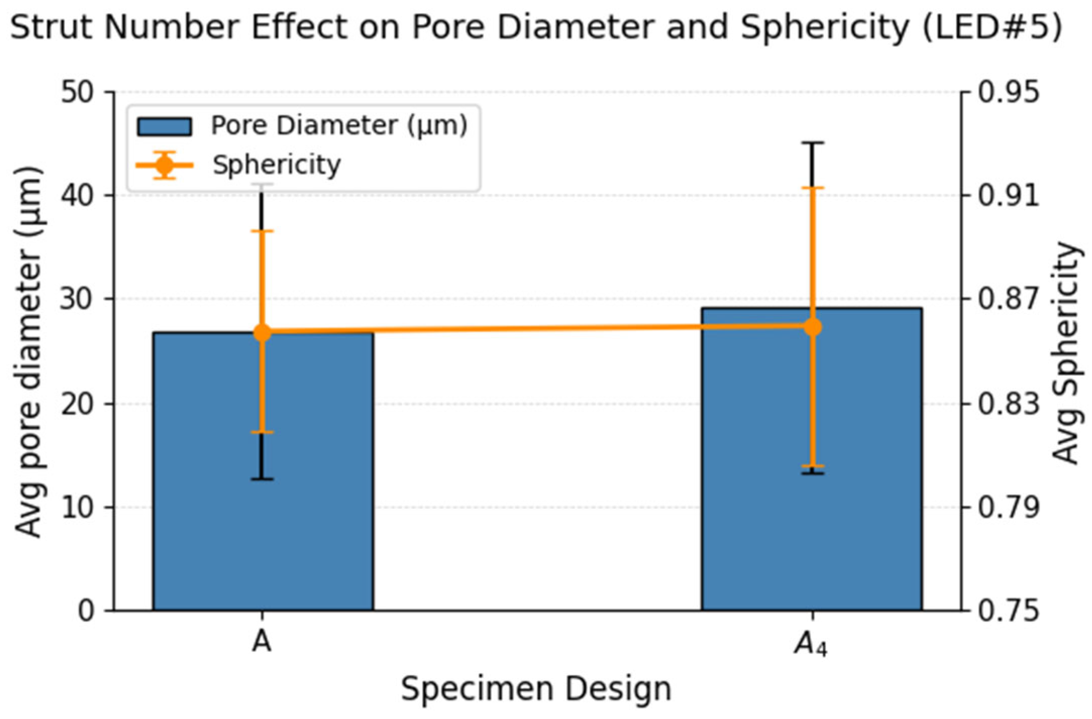
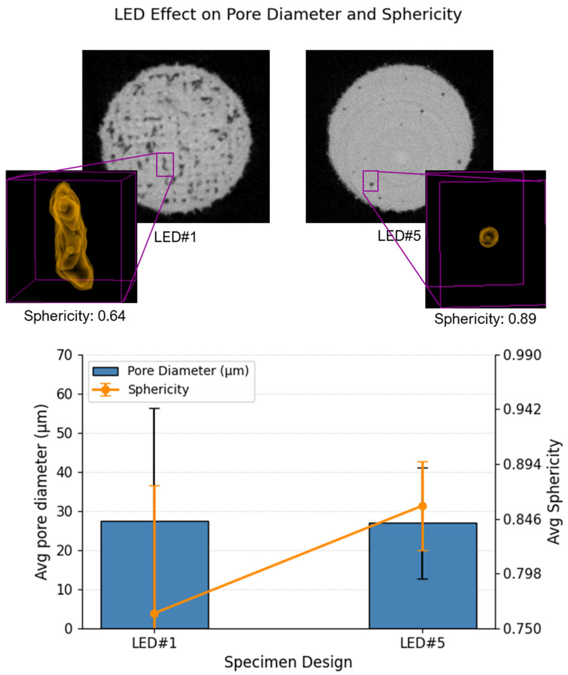
Furthermore, pore characteristics other than the amount of porosity were investigated. Figure 12 shows that both A and A4 specimens exhibit comparable average pore diameters and sphericity under LED#5, indicating that pore characteristics are primarily governed by LED rather than strut number or cross-sectional area.

3.1.3. Strut Shape Effect

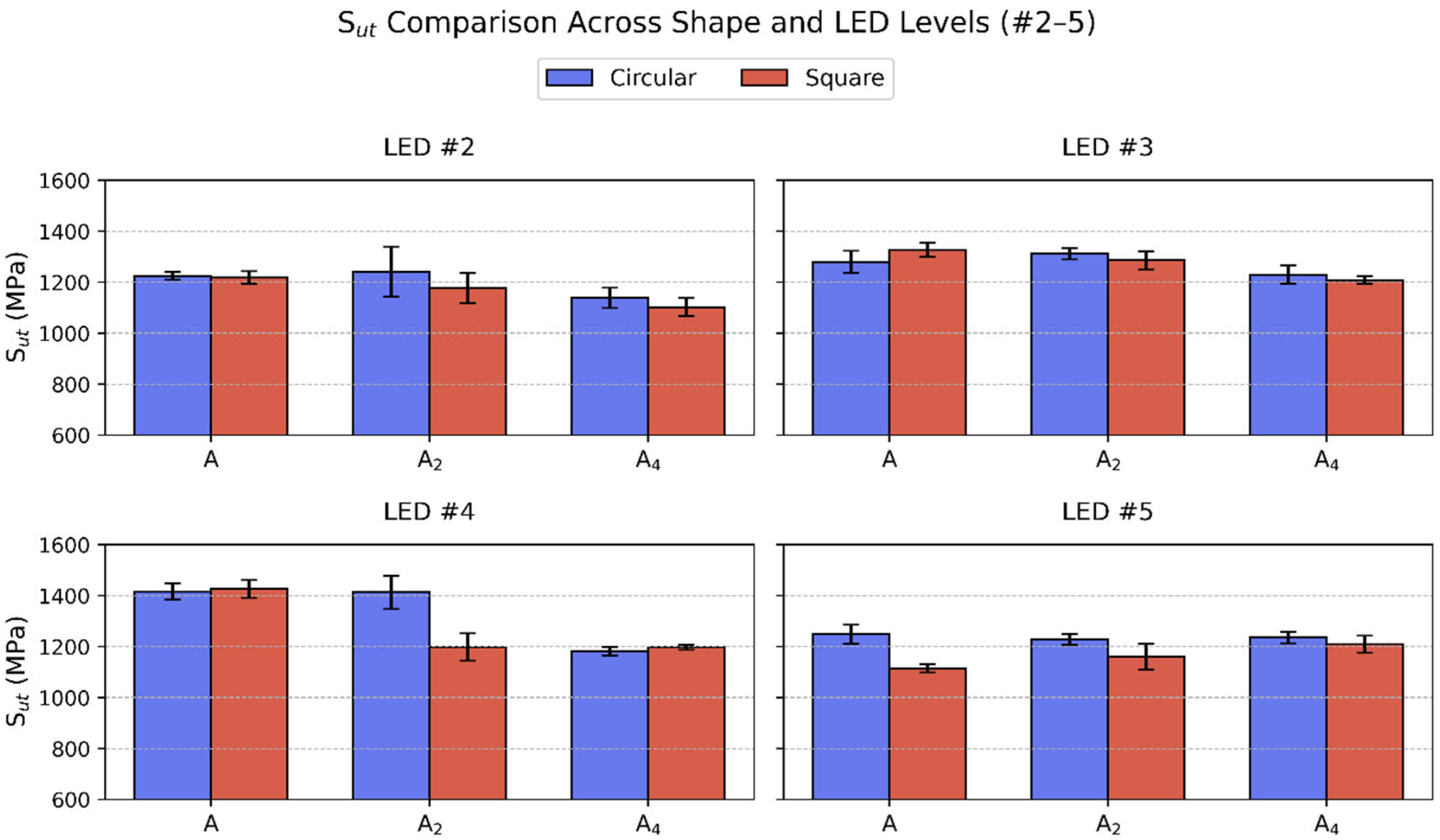
The effect of strut cross-sectional shape on tensile strength was evaluated across LED levels #2 to #5 for both circular and square geometries, as shown in Figure 13. Across all combinations of LED and geometry, the differences in Sut between circular and square shapes were minor and largely within error margins, indicating that shape has minimal effect on tensile strength under typical processing conditions.
However, under the extremely low-energy input condition (LED#1), square-shaped specimens exhibited noticeably lower Sut compared to their circular counterparts, particularly in the A and A4 configurations, as shown in Figure 14. This reduction may be attributed to stress concentrations at sharp corners, which promote early failure under tensile load.
These findings indicate that while strut shape does not significantly influence tensile performance under middle-range LEDs (LED#2–4), it may become critical in extreme conditions involving very low energy input where defect sensitivity is high.
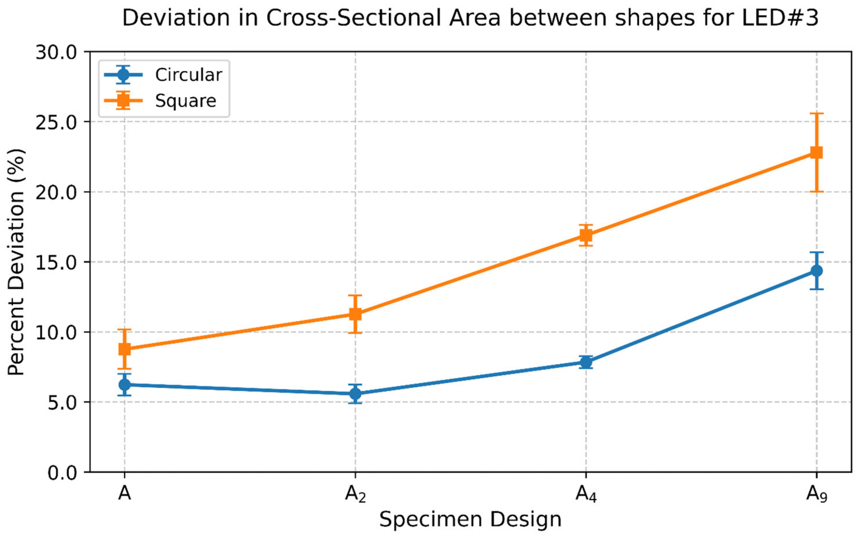
Before mechanical testing, the actual cross-sectional areas of the printed struts were measured using calipers to obtain accurate tensile properties. However, trends in fabricated dimensions emerge when compared against the nominal design values across different specimen configurations. Figure 15 shows the mean percentage deviation in different specimen design configurations for both shapes under LED#3. The square specimens consistently showed larger deviations from their intended geometry compared to circular ones. This is possibly due to square specimens with a larger circumference at the same specimen size adding more powder particles at the melt pool boundary. Moreover, the deviation increased with strut count, especially for square designs. This is likely because each additional strut introduces a compounding effect for geometric inaccuracy, leading to greater overall deviation.

3.2. Process Parameter Effect

In L-PBF, LED serves as a critical process parameter that governs melt pool dynamics, fusion quality, and ultimately mechanical performance. Prior studies have shown that optimal part quality is achieved within a narrow LED process window that balances complete melting with thermal stability [34,35]. Deviating from this optimal range—whether toward insufficient energy input or excessive overheating—can result in detrimental porosity, dimensional deviations, and degraded mechanical behavior.
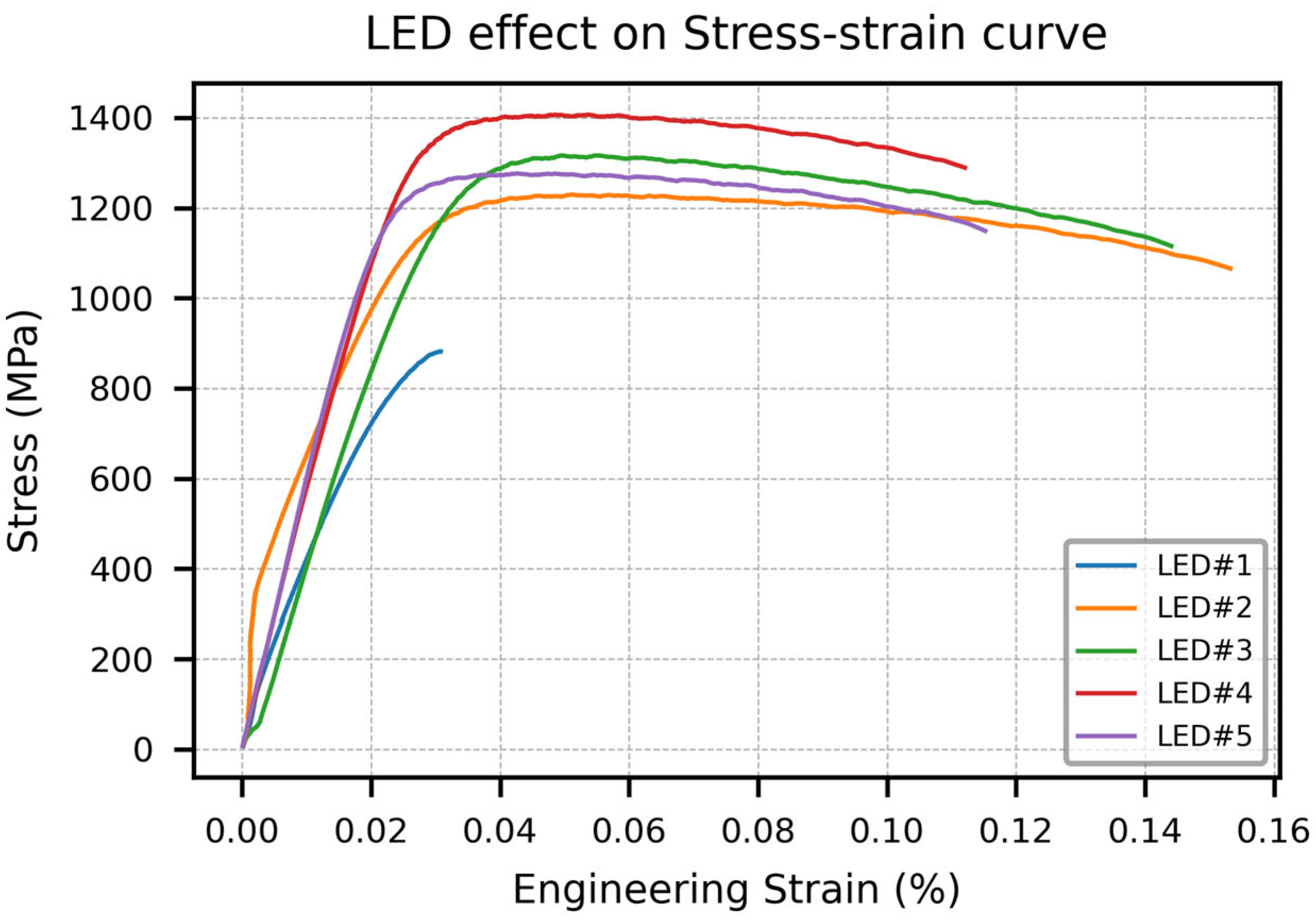
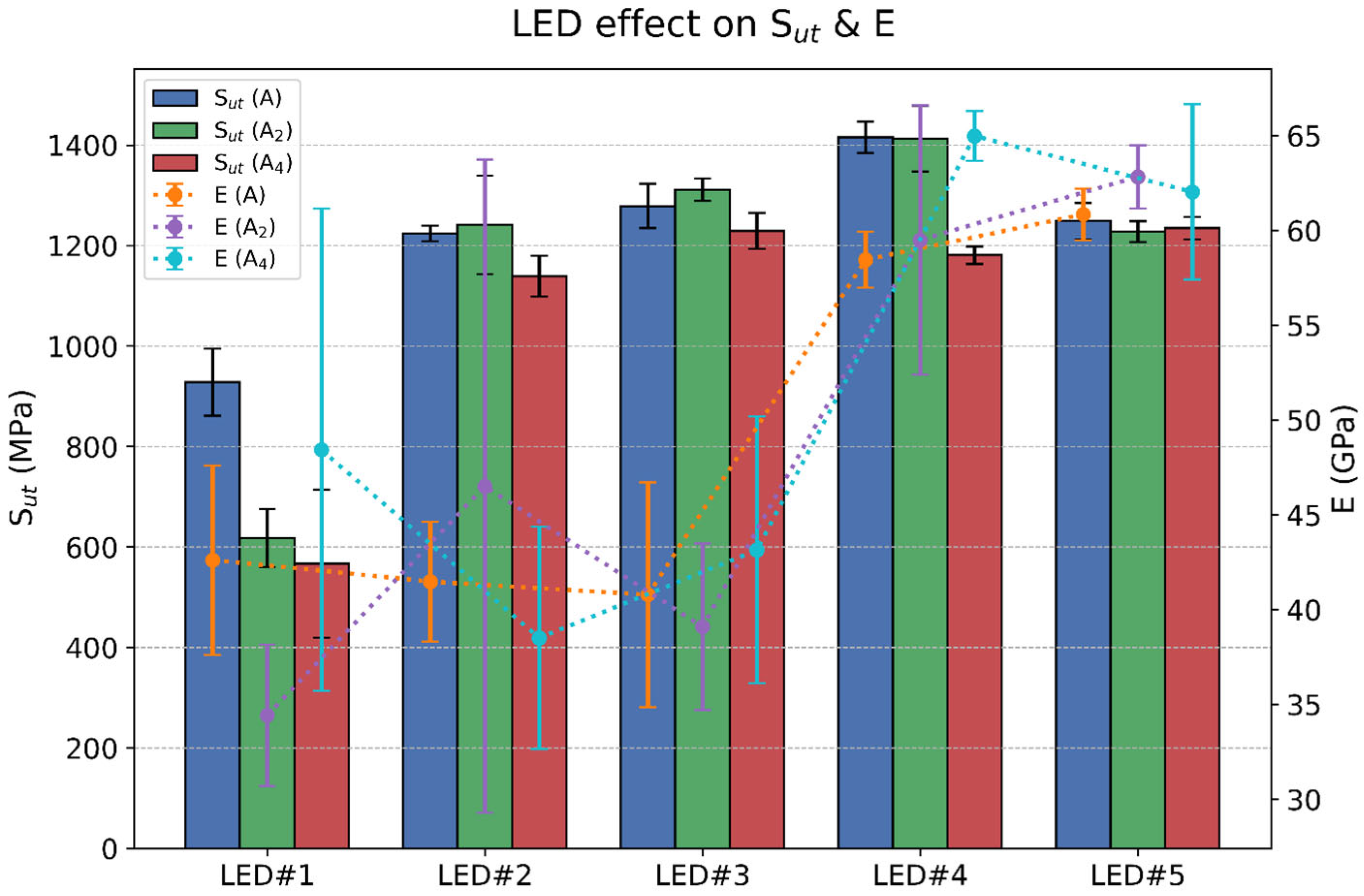
Figure 16 and Figure 17 shows the influence of LED on mechanical behavior in this study. As LED increases, mechanical properties improve up to an optimal point, beyond which further increases result in diminished tensile performance. Figure 16 presents representative stress–strain curves for the single-strut specimen (A) fabricated under varying LED levels. LED#1, the lowest energy input condition (0.075 J/mm), results in significantly lower mechanical strength compared to other LEDs. This is consistent with the Sut and E trends shown in Figure 17, where LED#1 consistently yields the weakest mechanical properties across all strut configurations. A substantial increase in Sut (35–100%) is observed going from LED#1 to LED #2. The low energy input of LED#1 leads to incomplete melting and LoF porosity, which is particularly harmful to tensile properties—a phenomenon widely documented in prior studies [24,36,37].
As the LED increases from LED#1 to LED#4, both Sut and E show a consistent upward trend, indicating better fusion and stronger bonding between layers, similar to results found by Joshi et al. [26]. Particularly, E increases by approximately 50% from LED#3 to LED#4, and this elevated stiffness is sustained through LED#5. However, the highest overall mechanical performance is observed at LED#4, suggesting that this mid-to-high energy input provides an optimal balance between full melting and melt pool stability. At LED#5, a slight reduction in Sut is observed across most designs despite there being a high E. This suggests that excessive energy input, while beneficial for stiffness, may also introduce keyhole porosity or thermal-induced microstructural defects that weaken ultimate strength, a behavior also reported by Kaschel et al. [38] when the laser power exceeds optimal thresholds.
This hypothesis is further substantiated by the porosity measurements shown in Figure 18. Micro-CT scans reveal specimens fabricated under LED#1 exhibit the highest porosity (~5%), confirming the presence of LoF pores due to insufficient melting. In contrast, LED#3 and LED#4 specimens are nearly pore-free, aligning with the observed peak in mechanical performance. However, LED#5 shows a measurable increase in porosity (0.229%), which may stem from keyhole-induced gas entrapment caused by excessive energy density. This type of porosity has been linked to instability in melt pool dynamics and has been shown to reduce fatigue and tensile performance despite appearing small in volume [24].
The morphological differences between LoF pores found in LED#1 and keyhole pores in LED#5 are highlighted in Figure 19. Although the average pore size is similar between keyhole and LoF pores, LoF pores show much more variation because they include both small round pores and large irregular ones. This irregularity is further reflected in their sphericity values. The large irregular pores have very low sphericity, as shown in Figure 7. However, many small round pores raise the average sphericity and increase the spread in values. In contrast, keyhole-induced pores resulting from very high energy input at LED#5 show lower variation in pore diameter and sphericity. These differences highlight the distinct formation mechanisms and morphological characteristics of porosity associated with low and high energy density conditions.
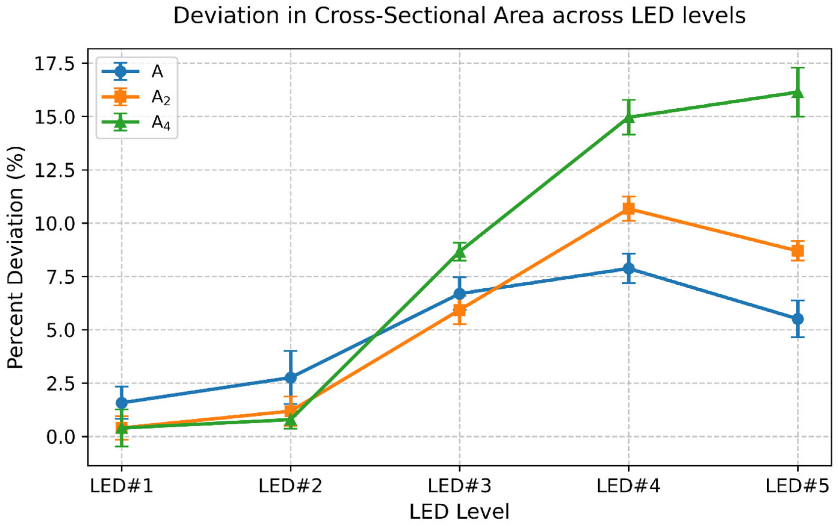
In addition to mechanical properties and porosity, deviations in fabricated cross-sectional areas were analyzed across LED levels using caliper measurements. As shown in Figure 20, dimensional deviation tends to increase with LED, especially for A2 and A4 specimens. This suggests that higher energy input may lead to over-melting or heat accumulation, causing struts to fuse beyond their designed boundaries. The trend is most pronounced in multi-strut configurations, likely due to thermal interaction between adjacent struts. While not directly tied to tensile failure in this study, such deviations are critical for applications requiring high geometric precision.
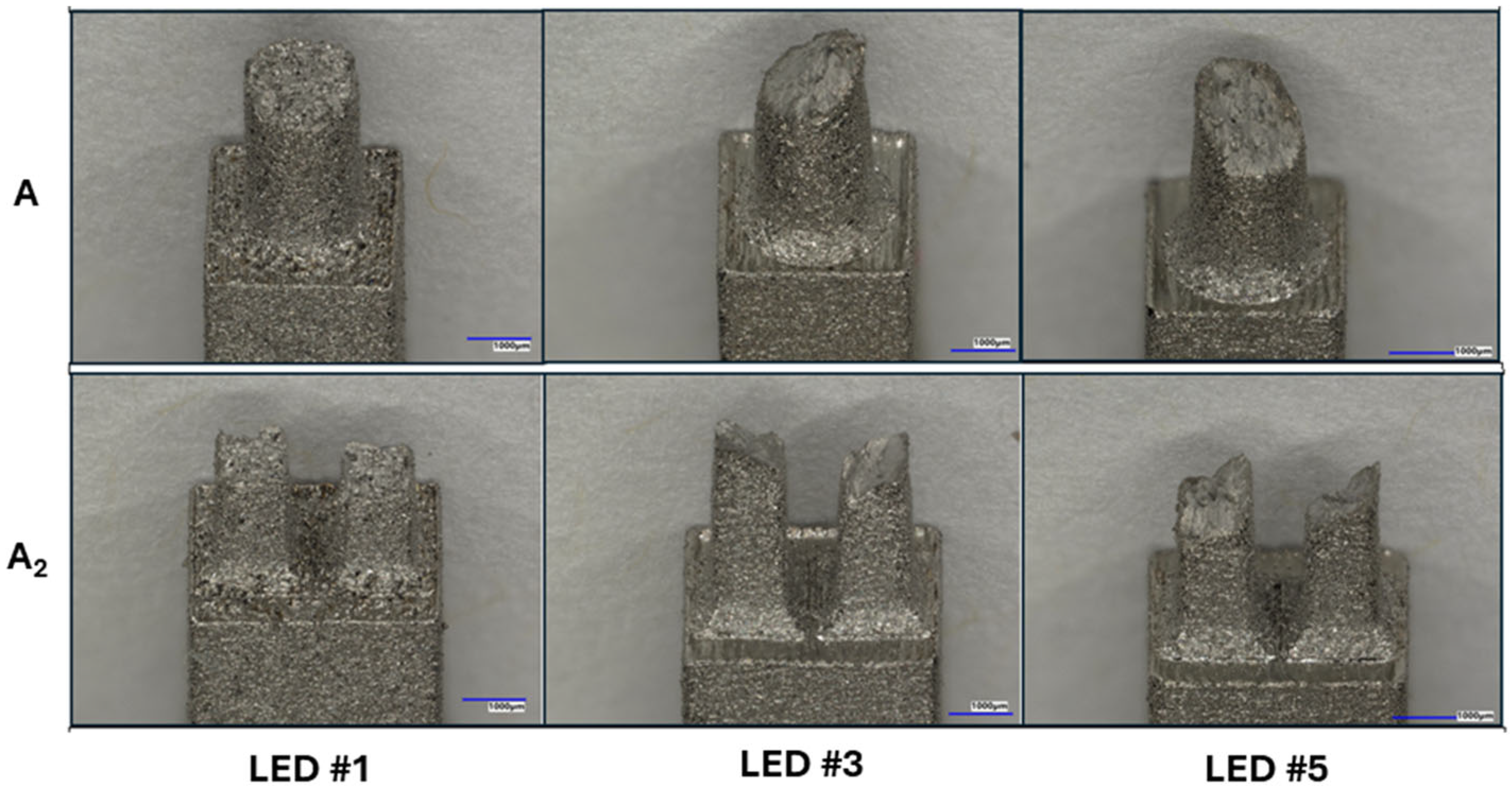
Fracture surface observations, shown in Figure 21, reveal a clear influence of LED on failure mode. At LED#1, specimens fractured along flat planes parallel to the build plate, indicating brittle failure due to poor interlayer bonding from insufficient fusion. In contrast, mid and high LED specimens exhibited angled fracture surfaces (~45°), typical of ductile failure where plastic deformation precedes fracture. These results suggest improved fusion quality and energy absorption capacity at higher LEDs.

3.3. Fracture Location Along Strut Length

Furthermore, the broken specimens were visually inspected, with representative images shown in Figure 22. For specimens with the same geometry and number of struts, the breaking regions were consistently located across different parameters (Figure 22a). Notably, in the nine-strut specimens, fractures were observed in the upper section along the build direction, indicating a weaker region than the rest (Figure 22b). In contrast, no significant differences were observed between the different geometries (Figure 22c).

4. Conclusions

This study addresses a research gap by systematically investigating how strut geometry, configuration, and processing parameters collectively influence the mechanical properties of thin Ti-6Al-4V struts fabricated by laser powder bed fusion (L-PBF). While prior research has often focused on lattice structures at the macro scale or on individual factors such as porosity or build orientation in isolation, this work explores the combined effects of strut number, size, shape, and linear energy density (LED). Tensile specimens were designed with both single and multi-strut configurations, incorporating circular and square cross-sections. They were fabricated across five LED conditions, namely, LED#1 to LED#5: 0.075 J/mm, 0.100 J/mm, 0.150 J/mm, 0.200 J/mm, and 0.238 J/mm, respectively. Additionally, single-strut specimens of varying sizes were produced under the machine-recommended LED setting. Mechanical behavior was evaluated through tensile testing, along with micro-CT for porosity characterization. The experimental approach provides new insights into how geometric and processing interactions govern mechanical response, informing more reliable lattice structure design in L-PBF applications. The key findings are summarized below:
  • Increasing the number of struts while maintaining a constant total cross-sectional area led to a reduction in tensile strength. Notably, the ultimate tensile strength (Sut) dropped sharply in nine-strut configurations (A9), with ~70% reduction in LED#2 specimens and ~35% reduction in LED#3 and LED#4 specimens. The combination of low energy input and high strut number produced a compounding negative effect on tensile strength.
  • Multi-strut configurations consistently performed 5–10% lower than equivalent single-strut arrangements. However, in the case of the nine-strut configuration (A9) versus its single-strut counterpart (A/9), the multi-strut specimen exhibited a 25–50% lower Sut.
  • Sut remained relatively consistent across most strut sizes, with only minor deviations. However, at the smallest scale (A/9), ~20% reduction in strength was observed. This reduction is likely due to increased susceptibility to surface defects at smaller scales.
  • Circular and square cross-sections demonstrated comparable tensile properties under high energy inputs, with only 1–5% variance in Sut. However, at low energy input (LED#1), square specimens performed noticeably worse, possibly due to stress concentrations at sharp corners that were exacerbated by lack-of-fusion defects and promoted early failure.
  • Among all variables, LED exhibited the strongest influence on tensile behavior. As LED increased from 0.075 J/mm to approximately 0.2 J/mm, both strength and stiffness improved significantly, corresponding with reduced porosity and improved fusion. Beyond this optimal LED range (i.e., at LED#5), a slight decline in Sut was observed despite a sustained high E. This correlated with keyhole-induced porosity and thermal instability in the melt pool at excessive energy densities, consistent with prior literature on keyhole-induced defects.
  • Dimensional deviations increased with LED level, reaching 15–20% at LED#5. Square cross-sections showed 5–15% higher deviation than circular ones. Furthermore, deviations were 5–10% more for multi-strut configurations compared to single struts.

Author Contributions

Conceptualization, B.A. and K.C.; methodology, R.I. and B.A.; software, R.I. and B.A.; validation, R.I. and B.A.; formal analysis, R.I.; investigation, R.I.; resources, K.C.; data curation, R.I.; writing—original draft preparation, R.I. and B.A.; writing—review and editing, K.C.; visualization, R.I.; supervision, K.C.; project administration, K.C.; funding acquisition, K.C. All authors have read and agreed to the published version of the manuscript.

Funding

This research was funded by the National Science Foundation, grant number CMMI-1921263.

Data Availability Statement

The original contributions presented in this study are included in the article. Further inquiries can be directed to the corresponding author.

Acknowledgments

The authors would like to thank Hamilton Bryan and Danny Tran for their valuable contributions to this project. Their insights and assistance were instrumental in the development and completion of this research.

Conflicts of Interest

The authors declare no conflicts of interest. The funders had no role in the design of the study; in the collection, analyses, or interpretation of data; in the writing of the manuscript; or in the decision to publish the results.

Abbreviations

The following abbreviations are used in this manuscript:
AMAdditive manufacturing
L-PBFLaser powder bed fusion
DICDigital image correlation
XCTX-ray computed tomography
LoFLack of fusion
ASTMAmerican Society for Testing and Materials
VEDVolumetric energy density
LEDLinear energy density
EDMElectrical discharge machine

References

  1. Gibson, I.; Rosen, D.W.; Stucker, B. Additive Manufacturing Technologies: Rapid Prototyping to Direct Digital Manufacturing; Springer: Boston, MA, USA, 2010. [Google Scholar] [CrossRef]
  2. Orquéra, M.; Campocasso, S.; Millet, D. Design for Additive Manufacturing Method for a Mechanical System Downsizing. Procedia CIRP 2017, 60, 223–228. [Google Scholar] [CrossRef]
  3. Mahmoud, D.; Elbestawi, M.A. Lattice Structures and Functionally Graded Materials Applications in Additive Manufacturing of Orthopedic Implants: A Review. J. Manuf. Mater. Process. 2017, 1, 13. [Google Scholar] [CrossRef]
  4. Alabort, E.; Barba, D.; Reed, R.C. Design of metallic bone by additive manufacturing. Scr. Mater. 2019, 164, 110–114. [Google Scholar] [CrossRef]
  5. Korkmaz, M.E.; Gupta, M.K.; Robak, G.; Moj, K.; Krolczyk, G.M.; Kuntoğlu, M. Development of lattice structure with selective laser melting process: A state of the art on properties, future trends and challenges. J. Manuf. Process. 2022, 81, 1040–1063. [Google Scholar] [CrossRef]
  6. Mullen, L.; Stamp, R.C.; Brooks, W.K.; Jones, E.; Sutcliffe, C.J. Selective Laser Melting: A regular unit cell approach for the manufacture of porous, titanium, bone in-growth constructs, suitable for orthopedic applications. J. Biomed. Mater. Res. B Appl. Biomater. 2009, 89B, 325–334. [Google Scholar] [CrossRef] [PubMed]
  7. Nguyen, H.D.; Pramanik, A.; Basak, A.K.; Dong, Y.; Prakash, C.; Debnath, S.; Shankar, S.; Jawahir, I.S.; Dixit, S.; Buddhi, D. A critical review on additive manufacturing of Ti-6Al-4V alloy: Microstructure and mechanical properties. J. Mater. Res. Technol. 2022, 18, 4641–4661. [Google Scholar] [CrossRef]
  8. Liu, S.; Shin, Y.C. Additive manufacturing of Ti6Al4V alloy: A review. Mater. Des. 2019, 164, 107552. [Google Scholar] [CrossRef]
  9. Veiga, C.; Davim, J.P.; Loureiro, A.J.R. Properties and Applications of Titanium Alloys: A Brief Review. J. Rev. Adv. Mater. Sci. 2012, 32, 14–34. [Google Scholar]
  10. Sing, S.L.; Wiria, F.E.; Yeong, W.Y. Selective laser melting of lattice structures: A statistical approach to manufacturability and mechanical behavior. Robot. Comput.-Integr. Manuf. 2018, 49, 170–180. [Google Scholar] [CrossRef]
  11. Alsalla, H.; Hao, L.; Smith, C. Fracture toughness and tensile strength of 316L stainless steel cellular lattice structures manufactured using the selective laser melting technique. Mater. Sci. Eng. A 2016, 669, 1–6. [Google Scholar] [CrossRef]
  12. Yang, K.; Wang, J.; Jia, L.; Yang, G.; Tang, H.; Li, Y. Additive manufacturing of Ti-6Al-4V lattice structures with high structural integrity under large compressive deformation. J. Mater. Sci. Technol. 2019, 35, 303–308. [Google Scholar] [CrossRef]
  13. Köhnen, P.; Haase, C.; Bültmann, J.; Ziegler, S.; Schleifenbaum, J.H.; Bleck, W. Mechanical properties and deformation behavior of additively manufactured lattice structures of stainless steel. Mater. Des. 2018, 145, 205–217. [Google Scholar] [CrossRef]
  14. Leary, M.; Mazur, M.; Elambasseril, J.; McMillan, M.; Chirent, T.; Sun, Y.; Qian, M.; Easton, M.; Brandt, M. Selective laser melting (SLM) of AlSi12Mg lattice structures. Mater. Des. 2016, 98, 344–357. [Google Scholar] [CrossRef]
  15. Dressler, A.D.; Jost, E.W.; Miers, J.C.; Moore, D.G.; Seepersad, C.C.; Boyce, B.L. Heterogeneities dominate mechanical performance of additively manufactured metal lattice struts. Addit. Manuf. 2019, 28, 692–703. [Google Scholar] [CrossRef]
  16. Aiza, I.; Baldi, C.; de la Vega, F.M.; Sebastiani, S.; Veronese, N.E.; Yousefi, M.; Mosallanejad, M.H.; Maleki, E.; Guagliano, M.; Iuliano, L.; et al. Effects of build orientation and inclined features on physical, microstructural and mechanical properties of powder bed fusion additively manufactured metallic parts. Prog. Mater. Sci. 2025, 147, 101357. [Google Scholar] [CrossRef]
  17. Murchio, S.; Dallago, M.; Zanini, F.; Carmignato, S.; Zappini, G.; Berto, F.; Maniglio, D.; Benedetti, M. Additively manufactured Ti-6Al-4V thin struts via laser powder bed fusion: Effect of building orientation on geometrical accuracy and mechanical properties. J. Mech. Behav. Biomed. Mater. 2021, 119, 104495. [Google Scholar] [CrossRef] [PubMed]
  18. Hossain, U.; Ghouse, S.; Nai, K.; Jeffers, J.R.T. Mechanical and morphological properties of additively manufactured SS316L and Ti6Al4V micro-struts as a function of build angle. Addit. Manuf. 2021, 46, 102050. [Google Scholar] [CrossRef]
  19. Bültmann, J.; Merkt, S.; Hammer, C.; Hinke, C.; Prahl, U. Scalability of the mechanical properties of selective laser melting produced micro-struts. J. Laser Appl. 2015, 27, S29206. [Google Scholar] [CrossRef]
  20. Maskery, I.; Aboulkhair, N.T.; Corfield, M.R.; Tuck, C.; Clare, A.T.; Leach, R.K.; Wildman, R.D.; Ashcroft, I.A.; Hague, R.J.M. Quantification and characterisation of porosity in selectively laser melted Al–Si10–Mg using X-ray computed tomography. Mater. Charact. 2016, 111, 193–204. [Google Scholar] [CrossRef]
  21. Zhou, X.; Wang, D.; Liu, X.; Zhang, D.; Qu, S.; Ma, J.; London, G.; Shen, Z.; Liu, W. 3D-imaging of selective laser melting defects in a Co–Cr–Mo alloy by synchrotron radiation micro-CT. Acta Mater. 2015, 98, 1–16. [Google Scholar] [CrossRef]
  22. Romano, S.; Abel, A.; Gumpinger, J.; Brandão, A.D.; Beretta, S. Quality control of AlSi10Mg produced by SLM: Metallography versus CT scans for critical defect size assessment. Addit. Manuf. 2019, 28, 394–405. [Google Scholar] [CrossRef]
  23. Voisin, T.; Calta, N.P.; Khairallah, S.A.; Forien, J.-B.; Balogh, L.; Cunningham, R.W.; Rollett, A.D.; Wang, Y.M. Defects-dictated tensile properties of selective laser melted Ti-6Al-4V. Mater. Des. 2018, 158, 113–126. [Google Scholar] [CrossRef]
  24. Kan, W.H.; Gao, M.; Zhang, X.; Liang, E.; Chiu, N.S.L.; Lim, C.V.S.; Huang, A. The influence of porosity on Ti-6Al-4V parts fabricated by laser powder bed fusion in the pursuit of process efficiency. Int. J. Adv. Manuf. Technol. 2022, 119, 5417–5438. [Google Scholar] [CrossRef]
  25. Joshi, K.; Promoppatum, P.; Quek, S.S.; Raghavan, S.; Johan, N.S.; Shukla, S.; Samudrala, S.; Van Der Veen, S.; Jhon, M.H. Effect of porosity distribution on the strength and strain-to-failure of Laser-Powder Bed Fusion printed Ti-6Al-4V. Addit. Manuf. 2023, 75, 103738. [Google Scholar] [CrossRef]
  26. Shrestha, S.; Chou, K. Formation of keyhole and lack of fusion pores during the laser powder bed fusion process. Manuf. Lett. 2022, 32, 19–23. [Google Scholar] [CrossRef]
  27. Shrestha, S.; Starr, T.; Chou, K. A Study of Keyhole Porosity in Selective Laser Melting: Single-Track Scanning With Micro-CT Analysis. J. Manuf. Sci. Eng. 2019, 141, 071004. [Google Scholar] [CrossRef]
  28. Maskery, I.; Aremu, A.O.; Simonelli, M.; Tuck, C.; Wildman, R.D.; Ashcroft, I.A.; Hague, R.J.M. Mechanical Properties of Ti-6Al-4V Selectively Laser Melted Parts with Body-Centred-Cubic Lattices of Varying cell size. Exp. Mech. 2015, 55, 1261–1272. [Google Scholar] [CrossRef]
  29. Peyre, P.; Da Silva, J.R.; Hamouche, Z.; Helbert, A.-L.; Daligault, J.; Dal, M.; Coste, F.; Baudin, T. Size and build strategy effects for the L-PBF process applied to Inconel 625 vertical struts: A combined numerical and experimental approach. Int. J. Adv. Manuf. Technol. 2024, 132, 5063–5086. [Google Scholar] [CrossRef]
  30. Galindo-Fernández, M.A.; Mumtaz, K.; Rivera-Díaz-del-Castillo, P.E.J.; Galindo-Nava, E.I.; Ghadbeigi, H. A microstructure sensitive model for deformation of Ti-6Al-4V describing Cast-and-Wrought and Additive Manufacturing morphologies. Mater. Des. 2018, 160, 350–362. [Google Scholar] [CrossRef]
  31. Barba, D.; Alabort, C.; Tang, Y.T.; Viscasillas, M.J.; Reed, R.C.; Alabort, E. On the size and orientation effect in additive manufactured Ti-6Al-4V. Mater. Des. 2020, 186, 108235. [Google Scholar] [CrossRef]
  32. Zhao, X.; Li, S.; Zhang, M.; Liu, Y.; Sercombe, T.B.; Wang, S.; Hao, Y.; Yang, R.; Murr, L.E. Comparison of the microstructures and mechanical properties of Ti-6Al-4V fabricated by selective laser melting and electron beam melting. Mater. Des. 2016, 95, 21–31. [Google Scholar] [CrossRef]
  33. Promoppatum, P.; Taprachareon, K.; Chayasombat, B.; Tanprayoon, D. Understanding size-dependent thermal, microstructural, mechanical behaviors of additively manufactured Ti-6Al-4V from experiments and thermo-metallurgical simulation. J. Manuf. Process. 2022, 75, 1162–1174. [Google Scholar] [CrossRef]
  34. Narra, S.P.; Rollett, A.D.; Ngo, A.; Scannapieco, D.; Shahabi, M.; Reddy, T.; Pauza, J.; Taylor, H.; Gobert, C.; Diewald, E.; et al. Process qualification of laser powder bed fusion based on processing-defect structure-fatigue properties in Ti-6Al-4V. J. Mater. Process. Technol. 2023, 311, 117775. [Google Scholar] [CrossRef]
  35. Gordon, J.V.; Narra, S.P.; Cunningham, R.W.; Liu, H.; Chen, H.; Suter, R.M.; Beuth, J.L.; Rollett, A.D. Defect structure process maps for laser powder bed fusion additive manufacturing. Addit. Manuf. 2020, 36, 101552. [Google Scholar] [CrossRef]
  36. Liu, W.; Chen, C.; Shuai, S.; Zhao, R.; Liu, L.; Wang, X.; Hu, T.; Xuan, W.; Li, C.; Yu, J.; et al. Study of pore defect and mechanical properties in selective laser melted Ti6Al4V alloy based on X-ray computed tomography. Mater. Sci. Eng. A 2020, 797, 139981. [Google Scholar] [CrossRef]
  37. Montalbano, T.; Briggs, B.N.; Waterman, J.L.; Nimer, S.; Peitsch, C.; Sopcisak, J.; Trigg, D.; Storck, S. Uncovering the coupled impact of defect morphology and microstructure on the tensile behavior of Ti-6Al-4V fabricated via laser powder bed fusion. J. Mater. Process. Technol. 2021, 294, 117113. [Google Scholar] [CrossRef]
  38. Kaschel, F.R.; Celikin, M.; Dowling, D.P. Effects of laser power on geometry, microstructure and mechanical properties of printed Ti-6Al-4V parts. J. Mater. Process. Technol. 2020, 278, 116539. [Google Scholar] [CrossRef]
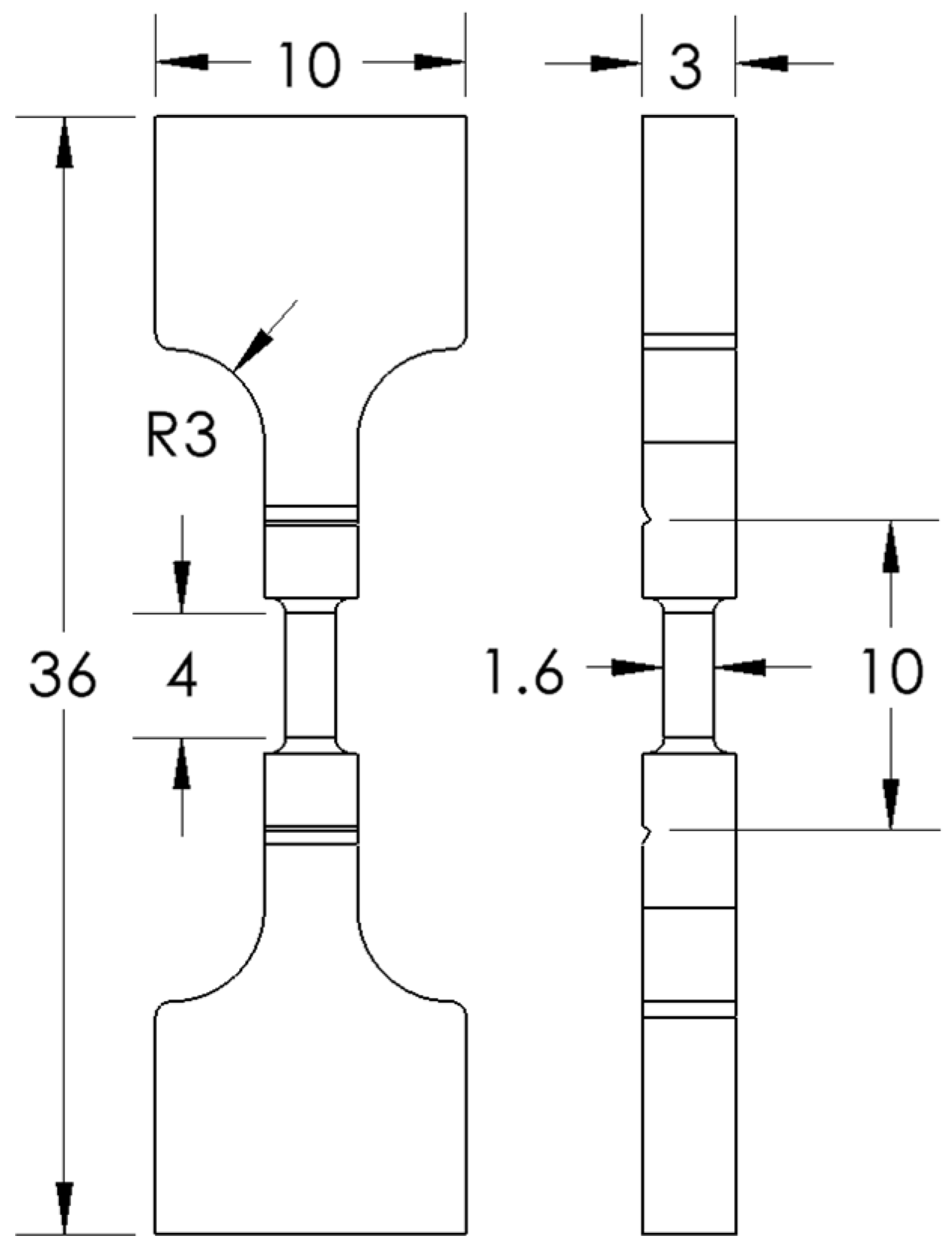
Figure 1. Specimen design following ASTM E8 flat specimen (all dimensions are in mm).
Metals 15 01009 g001
Figure 2. Fabricated specimens with 45-degree rotation on a titanium base plate.
Metals 15 01009 g002
Figure 3. Specimens after EDM and the support removal process. (a) Circular specimen with four struts; (b) circular specimen with two struts.
Metals 15 01009 g003
Figure 4. Fabrication failure in LED#1 and LED#5 9-strut specimens. (a) LED#5; (b) LED#1.
Metals 15 01009 g004
Figure 5. General tensile testing setup.
Metals 15 01009 g005
Figure 6. σ-ε curves of LED#3 specimens of different strut numbers with the same total cross-sectional area, A.
Metals 15 01009 g006
Figure 7. Mean Sut and E values of LED#2–4 specimens of different strut numbers with the same total cross-sectional area, A.
Metals 15 01009 g007
Figure 8. Mean Sut and E values of single vs. multi-strut configurations in LED#3 (mid LED).
Metals 15 01009 g008
Figure 9. Comparison of porosity in multi-strut (A9) and single-strut (A/9) specimens fabricated with identical strut size under LED#3.
Metals 15 01009 g009
Figure 10. Mean Sut and E values of LED#3 single struts with different cross-sectional areas.
Metals 15 01009 g010
Figure 11. Porosity levels in LED#5 (highest) and LED#1 (lowest) with A (one-strut) and A4 (four-strut) specimens.
Metals 15 01009 g011
Figure 12. Average pore diameter and sphericity in A (one-strut) and A4 (four-strut) specimens of LED#5.
Metals 15 01009 g012
Figure 13. Paired comparison of Sut and E between circular and square struts under LED (#2–5).
Metals 15 01009 g013
Figure 14. Paired comparison of Sut and E between circular and square struts under LED#1.
Metals 15 01009 g014
Figure 15. Mean percent deviation from nominal cross-sectional area in different specimen designs for both shapes in LED#3.
Metals 15 01009 g015
Figure 16. Representative stress–strain curves of the single-strut specimen (A) from different LED levels.
Metals 15 01009 g016
Figure 17. Effect of LED on Sut and E for different strut configurations.
Metals 15 01009 g017
Figure 18. Porosity levels and CT scans of specimen design A across LEDs #1–5.
Metals 15 01009 g018
Figure 19. Comparison of pore characteristics of extreme LEDs with micro-CT scans for visualization.
Metals 15 01009 g019
Figure 20. Percent deviation of measured cross-sectional area from nominal values across LEDs for different specimen designs.
Metals 15 01009 g020
Figure 21. Fracture angle comparison for A and A2 specimens under LED (#1, 3, and 5). Blue scale bars represent 1000 µm.
Metals 15 01009 g021
Figure 22. Examples of broken specimens: (a) square specimens with four struts, arranged from LED#1 to LED#5 from left to right; (b) circular specimens with nine struts, with LED#2 on the left and LED#4 on the right; (c) LED#3 specimens with varying strut numbers, where the left side of a pair is square and the right side is circular.
Metals 15 01009 g022
Table 1. The diameter of individual struts in specimens.
SpecimenAA2A4A9
Circular1.8 mm1.27 mm0.9 mm0.6 mm
Square1.6 mm1.13 mm0.8 mm0.53 mm
Table 2. Specimen design: constant total cross-sectional area to study the strut number effect.
AA2A4A9
Metals 15 01009 i001Metals 15 01009 i002Metals 15 01009 i003Metals 15 01009 i004
Table 3. Specimen design: decreasing cross-sectional area to study the strut size effect.
AA/2A/4A/9
Metals 15 01009 i005Metals 15 01009 i006Metals 15 01009 i007Metals 15 01009 i008
Table 4. Processing parameters and their respective linear energy density.
ParameterP
(W)
V
(mm/s)
LED
(J/mm)
Abv.Level
1608000.075LED#1Lowest
212012000.100LED#2Low
31208000.150LED#3Mid
41206000.200LED#4High
51908000.238LED#5Highest
Disclaimer/Publisher’s Note: The statements, opinions and data contained in all publications are solely those of the individual author(s) and contributor(s) and not of MDPI and/or the editor(s). MDPI and/or the editor(s) disclaim responsibility for any injury to people or property resulting from any ideas, methods, instructions or products referred to in the content.