Article

Numerical and Experimental Investigations on the Compressive Properties of the Graded BCC Lattice Cylindrical Shells Made of 316L Stainless Steel

1
Key Laboratory of Theory and Application of Advanced Materials Mechanics, Department of Engineering Mechanics, School of Physics and Mechanics, Wuhan University of Technology, Wuhan 430070, China
2
Research Center of Fluid Machinery Engineering and Technology, Jiangsu University, Zhenjiang 212013, China
*
Authors to whom correspondence should be addressed.
Metals 2025, 15(8), 895; https://doi.org/10.3390/met15080895
Submission received: 5 July 2025 / Revised: 4 August 2025 / Accepted: 8 August 2025 / Published: 10 August 2025
(This article belongs to the Special Issue Additive Manufactured Metal Structural Materials)

Abstract

Uniform and graded BCC lattice cylindrical shells were proposed, and the corresponding structural specimens were fabricated with 316L stainless steel material. Experimental testing and numerical simulations were both utilized to investigate the quasi-static and dynamic compression behavior of the uniform and graded BCC lattice cylindrical shells. Finite element results were compared with the experimental results. Parametric studies were conducted to study the effects of relative density, gradient distribution, and loading velocity on the mechanical properties and deformation features. When the relative density increased from 9% to 25%, a 175% increase in SEA could be seen. Graded BCC lattice cylindrical shells almost exhibited the same mechanical performance. When compared with the SEA value under low-speed loading conditions, a 26.95% maximum increase could be witnessed in the graded-5 specimen under high-speed loading. Testing results indicated that the proposed uniform and graded BCC lattice cylindrical shells exhibited fascinating quasi-static and dynamic mechanical behavior, which provided guidance for the design and application of next-generation lightweight materials with excellent protective properties.

1. Introduction

As next-generation architecture materials, cellular materials have huge application prospects in the fields of aerospace, shipping, and rail transit due to their superior mechanical performance, energy absorption, and multifunctional characteristics [1,2,3,4]. Among cellular materials, lattice materials have attracted the most attention for their designability in microstructures and their controllability in performance [5,6,7]. Generally, lattice materials include two-dimensional honeycombs and three-dimensional lattice structures [8,9,10,11], of which the latter ones possess a larger design space in microstructure patterns. Typical configurations of 3D lattices usually include simple cubic (SC) [12], body-centered cubic (BCC) [13], face-centered cubic (FCC) [14], diamond [15], octet truss [16], and BCC with Z strut [17]. Based on their deformation characteristics, lattice structures are typically classified into bending-dominated or stretching-dominated types [18,19,20]. Bending-dominated lattice structures generally have relatively smooth performance curves and excellent overall energy absorption characteristics [21]. Stretching-dominated lattice structures often experience a noticeable drop in stress after their initial peak stress, which reduces the overall energy absorption characteristics [22]. Therefore, bending-dominated lattice structures have been widely studied due to their excellent energy absorption characteristics. Among them, the body-centered cubic (BCC) lattice [23], as a representative of bending-dominated structures, has received extensive attention from scholars.
Configuration designs of the three-dimensional lattice structures are affected and restricted by manufacturing technology to a great extent. Thanks to the advent of additive manufacturing (AM) technology, complex topology configurations with customized patterns can be fabricated conveniently. Among all AM technologies, metal additive manufacturing, especially selective laser melting (SLM) technology [24], has greater vitality and application prospects thanks to its stable mechanical properties in fabricated samples. The SLM process can directly melt various metal powders, such as titanium, steel, cobalt–chromium, and aluminum alloys, and construct net-shape parts using a layer-by-layer method. For each layer, a scanning laser beam provides energy to locally melt a layer of deposited metal powder and fuse it to the previously melted layer [25,26]. The 316L stainless steel [24,27], as a typical material used in SLM technology, has also been widely studied by researchers. Smith et al. [28] investigated the mechanical behavior of the BCC structure composed of 316L stainless steel. Guo et al. [29] developed a model based on the beam cell for the 316L stainless steel BCC lattice structure. Based on this, 316L stainless steel was chosen as the matrix material in this paper. Moreover, the overall performance characteristics of the SLM-fabricated samples have greater advantages in actual engineering applications when compared with the competing technologies. Thus, these are of great significance in investigating the mechanical properties and deformation features of the additively manufactured metallic lattice structures. In the past few decades, many researchers have utilized theoretical analysis [30,31,32,33], experimental testing [34,35,36,37,38], and numerical simulations [39,40,41,42] to study the mechanical behavior of additively manufactured metallic lattice structures. Research results have indicated that the performance curves as well as the deformation processes are dependent on many factors, such as cell topology, geometric parameters, material characteristics, boundary conditions, and even the manufacturing process [43]. However, most existing studies have concentrated on investigating the mechanical properties of the cubic lattice structures [44], while limited research has been conducted on the cylindrical lattice structures [45,46,47].
As a design strategy, cylindrical lattice structures have advantages in some respects, especially in the medical field (e.g., vascular stents). Their internal hollow characteristic could play a role in transportation while ensuring high specific stiffness and high specific strength simultaneously. Some research has been conducted to gain insight into the mechanical behaviors of cylindrical lattice structures [48,49,50]. Zhang et al. [46] used selective laser melting (SLM) to prepare cylindrical biomimetic lattice artificial vertebrae with a dual-level gradient structure. The implant stability and biomechanical performance were enhanced, and the stress shielding was reduced. Shahriyari et al. [48] manufactured hollow AlSi10Mg cylindrical lattice structures through an indirect additive manufacturing approach and assessed their mechanical properties via quasi-static compression tests. However, to the best of our knowledge, limited systematic studies on SLM-fabricated bending-dominated BCC lattice cylindrical shells have been conducted, which deserve more attention.
Furthermore, as another design method, gradient design has shown great advantages in mechanical performance, deformation modes, and energy absorption characteristics [51,52,53]. By introducing the gradients globally or locally, performance curves as well as the deformation features can even be customized [54,55,56]. Wang et al. [55] designed a double-gradient energy absorption structure based on biomimetic gradient forms that can resist high-speed impacts. Wei et al. [57] introduced a gradient structure into a hybrid multicellular thin-walled structure inspired by the veins of the royal water lily leaf to study the effect of gradient on the structural mechanical properties. However, the existing studies mainly focused on the gradient design of the cubic lattice structures [44], while limited gradient designs were performed for the cylindrical ones. The effects of the gradient on the cylindrical lattice structures were also unclear, which deserves further study.
Thus, in this paper, to resolve the issues mentioned above, systematic static and dynamic studies on the SLM-fabricated bending-dominant BCC cylindrical lattice structures were conducted. Both the uniform and graded structural patterns were designed and compared. The rest of this study is arranged as follows. Section 2 describes the materials, experiments and methodology. Section 3 presents results and discussions. Some conclusions are drawn in Section 4.

2. Materials, Experiments, and Methodology

2.1. Design of Structure

The topological configuration had a significant effect on the mechanical responses and deformation behavior of the target structures. The BCC lattice cubic cell was a typical topology that exhibited bending-dominated properties when they were loaded. By employing the mapping method proposed in [45], the corresponding BCC lattice cylindrical shell (LCS) was derived, as shown in Figure 1a. This specimen had 12 cells in circumferential directions and 3 layers in axial directions (i.e., Layer 1 to Layer 3 shown in Figure 1b). Other detailed dimensions are also shown in Figure 1b, with strut diameter D , inner diameter L 1 , outer diameter L 2 and height H . All the considered dimensions are listed in Table 1. In the following analysis, the inner diameter, outer diameter, and height are kept constant. The uniform and graded BCC LCS lattice structures were designed by selecting and combining different strut diameters in different layers. Five different relative densities of the uniform BCC LCS patterns were considered, and six different graded BCC LCS patterns were designed while ensuring constant relative density ( ρ ¯ ) of 0.17. These graded structures were created by arranging three uniform BCC structures with relative densities of 0.09, 0.17, and 0.25 in different ways.

2.2. Specimen Preparation

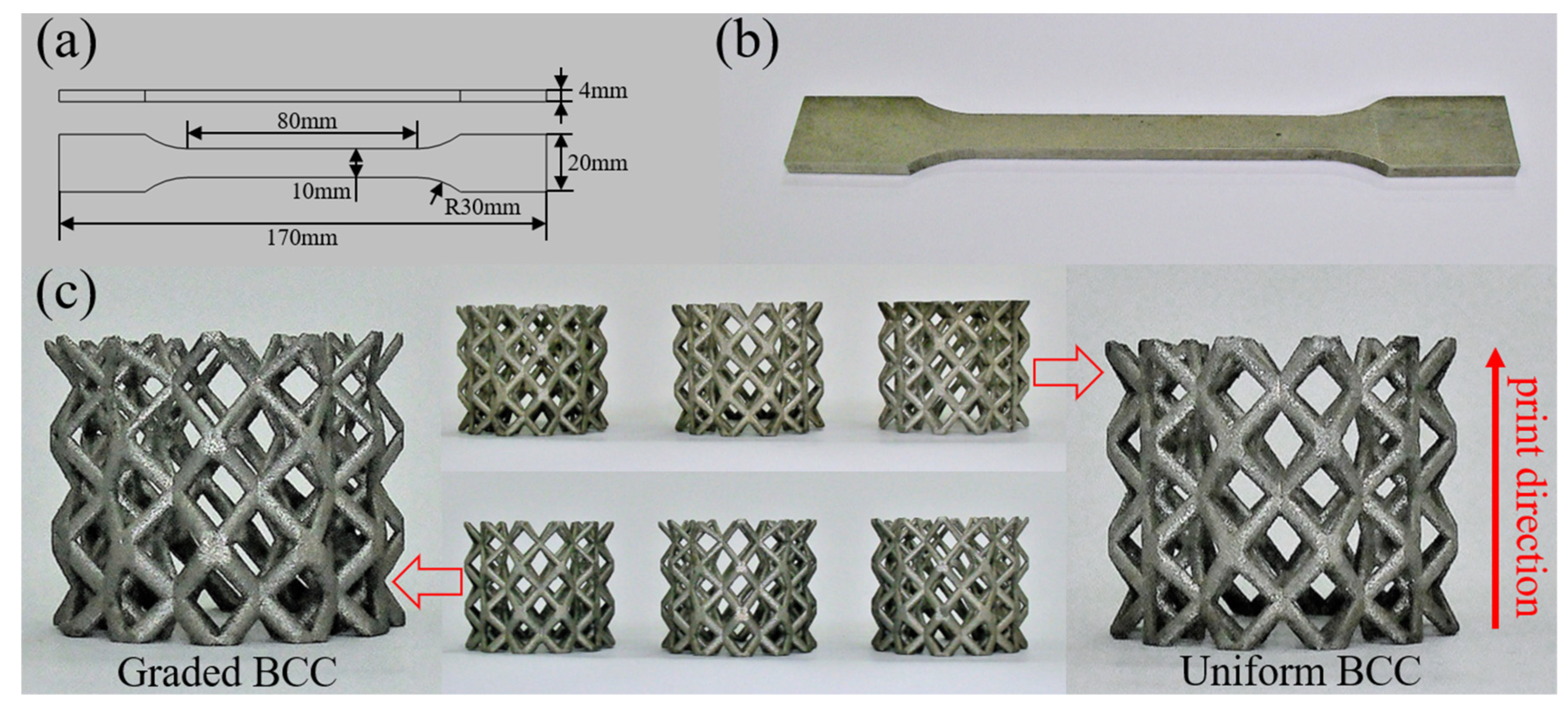
In this section, the uniform and graded BCC LCS specimens (i.e., the graded-1 pattern) with a relative density of 17% were fabricated via selective laser melting (SLM) using the Lim-X260A 3D printer (Lim, Jintian, China) with the 316L stainless steel powder material. The laser power was 350 W, and the scanning speed was 950 mm/s. Meanwhile, the layer thickness was 0.06 m m during the whole fabrication process. To reduce the residual stress, the samples were polished and annealed in the air furnace at 1150 °C for 2 h. In order to characterize the mechanical properties of the 316L stainless steel material, uniaxial tensile tests were also performed on the dog-bone specimens. As-designed geometric dimensions of the dog-bone specimens are shown in Figure 2a, and the 3D-printed dog-bone specimens are plotted in Figure 2b. As shown in Figure 2c, three identical specimens were fabricated to ensure the repeatability of the experiment, where good molding quality could be observed. Masses of all the specimens are listed in Table 2. The maximum error in mass between the as-fabricated and as-designed specimens was only 4.80%, which further proved the accuracy of the fabrication process.

2.3. Microstructure Characterization

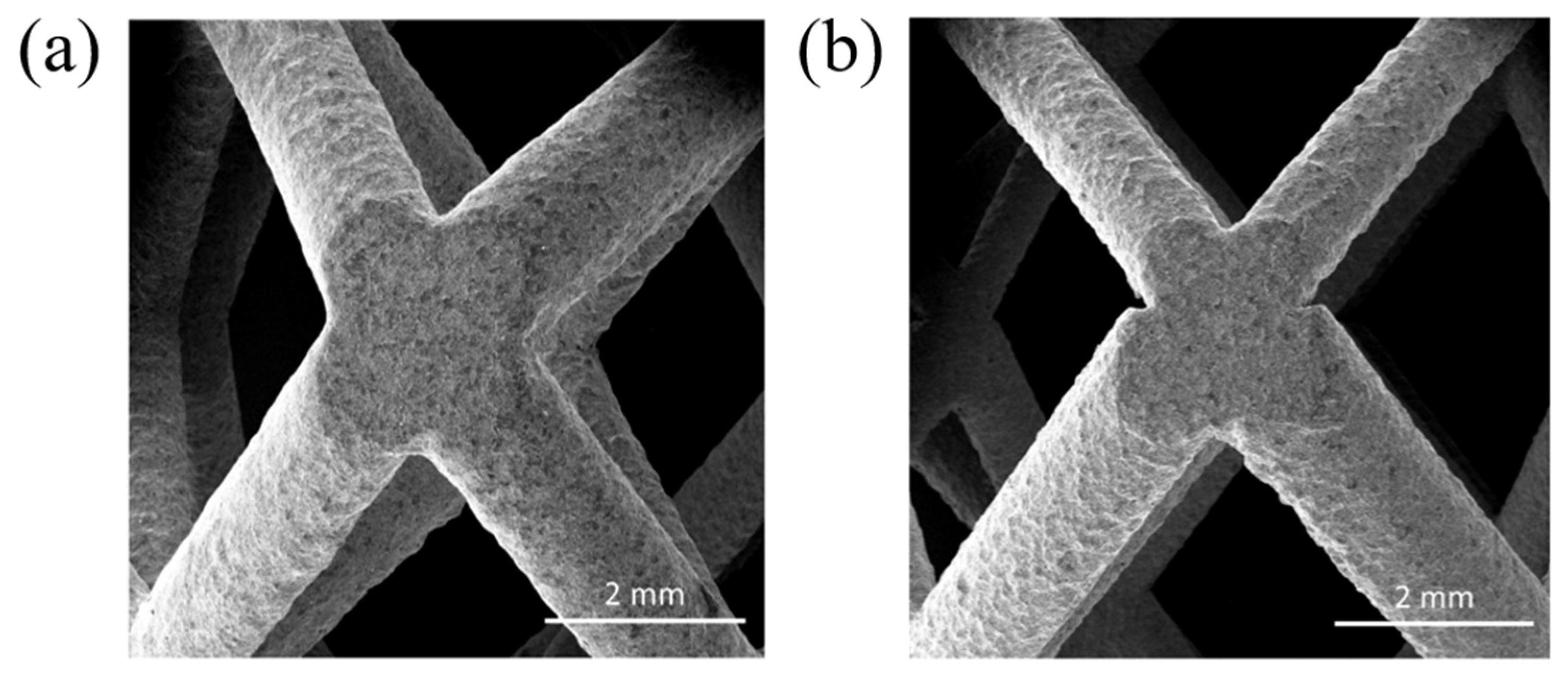
Herein, to gain insight into the microstructure of the as-fabricated uniform and graded BCC LCS specimens, scanning electron microscopy (SEM) was performed on a Quanta FEG250 microscope (FEI, Hillsborough, OR, USA). The working distance and accelerating voltage were 35.6 mm and 20 KV, respectively. SEM images of the uniform and graded BCC LCS specimens are shown in Figure 3. It was observed that no obvious defects or imperfections existed in either of the fabricated specimens. The specimens exhibited overall good molding quality. When compared with the uniform BCC LCS specimen (see Figure 3a), the variations in the strut diameters of the gradient specimen were clearly observed in different layers (see Figure 3b). The transition position of the strut diameter was also of good connectivity.

2.4. Quasi-Static Experimental Test

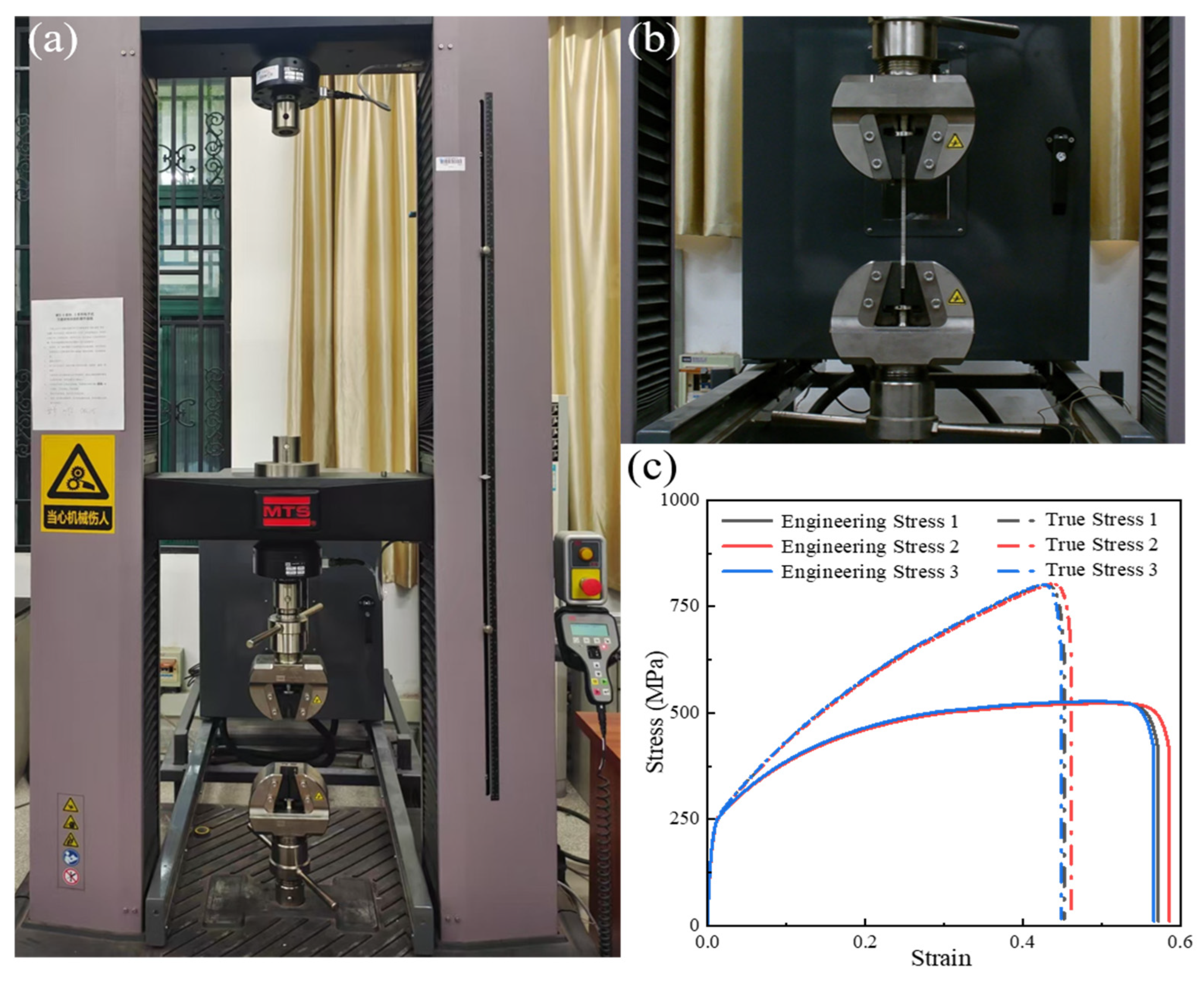
Quasi-static compression test was performed on the 300 KN MTS E45.305 (MTS Systems, Guangdong, China) universal testing machine (see Figure 4a) at a loading speed of 1.5 mm/min (i.e., strain rate of 0.001/s). Considering the property heterogeneity of the lattice materials brought by SLM, all the specimens were compressed along the layer direction. The compressive load and displacement data were obtained from the sensor and the indenter, respectively. Meanwhile, a normal digital camera, “SONY FDR-AX45” (SONY, Tokyo, Japan), was also employed to capture the macroscopic deformation processes of all the samples. The sampling frequency was 30 fps. Three repeated experiments were conducted to ensure the reliability of the experimental results.
To characterize the mechanical properties of the 316L stainless steel material, uniaxial tensile tests were carried out on the dog-bone specimens using a universal testing machine (MTS, Minnesota, MN, USA) equipped with a computer-controlled and data-acquisition system to automatically record force–displacement (see Figure 4b). Three repeated experiments were conducted. Typical tensile stress–strain curves are shown in Figure 4c, which were subsequently used as material model inputs to characterize the properties of the structural specimens. The curve showed the typical tensile characteristics of 316L stainless steel material: the linear elastic stage, plastic strengthening stage, and failure stage. According to the test results, Young’s modulus was 38 GPa, and the initial yield strength was 243 MPa. Ultimate strength was 800 MPa, and the corresponding ultimate strain was 0.43. All the parameters are listed in Table 3.

2.5. Computational Model

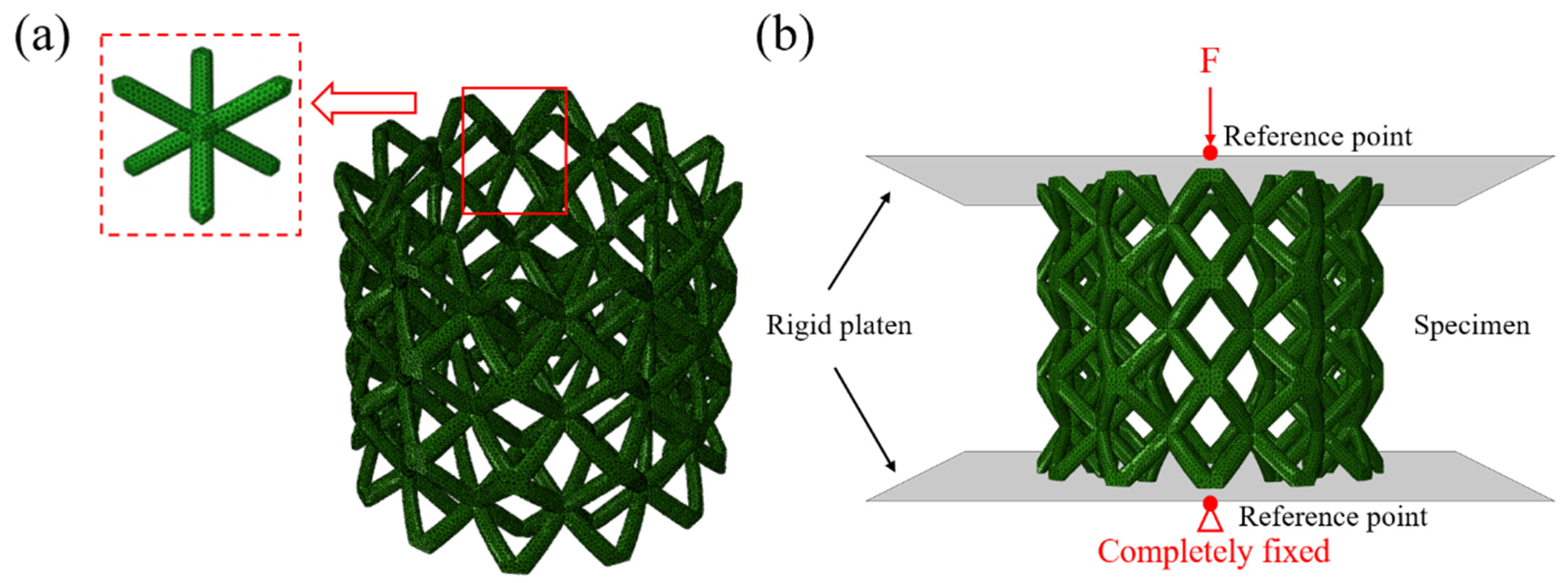
Figure 5 illustrates the finite element model and boundary conditions settings of the BCC LCS specimens. Using the Hypermesh software (V2023), a uniform mesh size was applied. The BCC LCS specimens were discretized with the modified quadratic tetrahedral element (C3D10M), which could effectively avoid volume self-locking and maintain high computational accuracy. To simulate the quasi-static compression process, two rigid plates with two reference points were created and attached to the opposite positions of the target structure. The bottom plate was fixed, and the top one was loaded in the form of displacement. Rigid elements of R3D4 were adopted to discretize the plates. To avoid penetration, a general contact with a penalty friction coefficient of 0.1 was applied between the plates and the specimens during the whole compression process. Self-contact was also defined between the struts of the specimens. The input material parameters were based on the experimental results of the dog-bone specimens (i.e., Table 3). Mesh sensitivity analysis was also conducted to ensure the accuracy of simulation results. All the simulation processes were conducted using the commercial finite element software ABAQUS/Explicit (V6.14).
For the simulation of the dynamic compression process, a constant velocity loading was applied to impose strain rates of different magnitudes. Other settings were the same as those under the quasi-static conditions.

3. Results and Discussion

3.1. Quasi-Static Compression Mechanical Behavior

3.1.1. Experimental Results

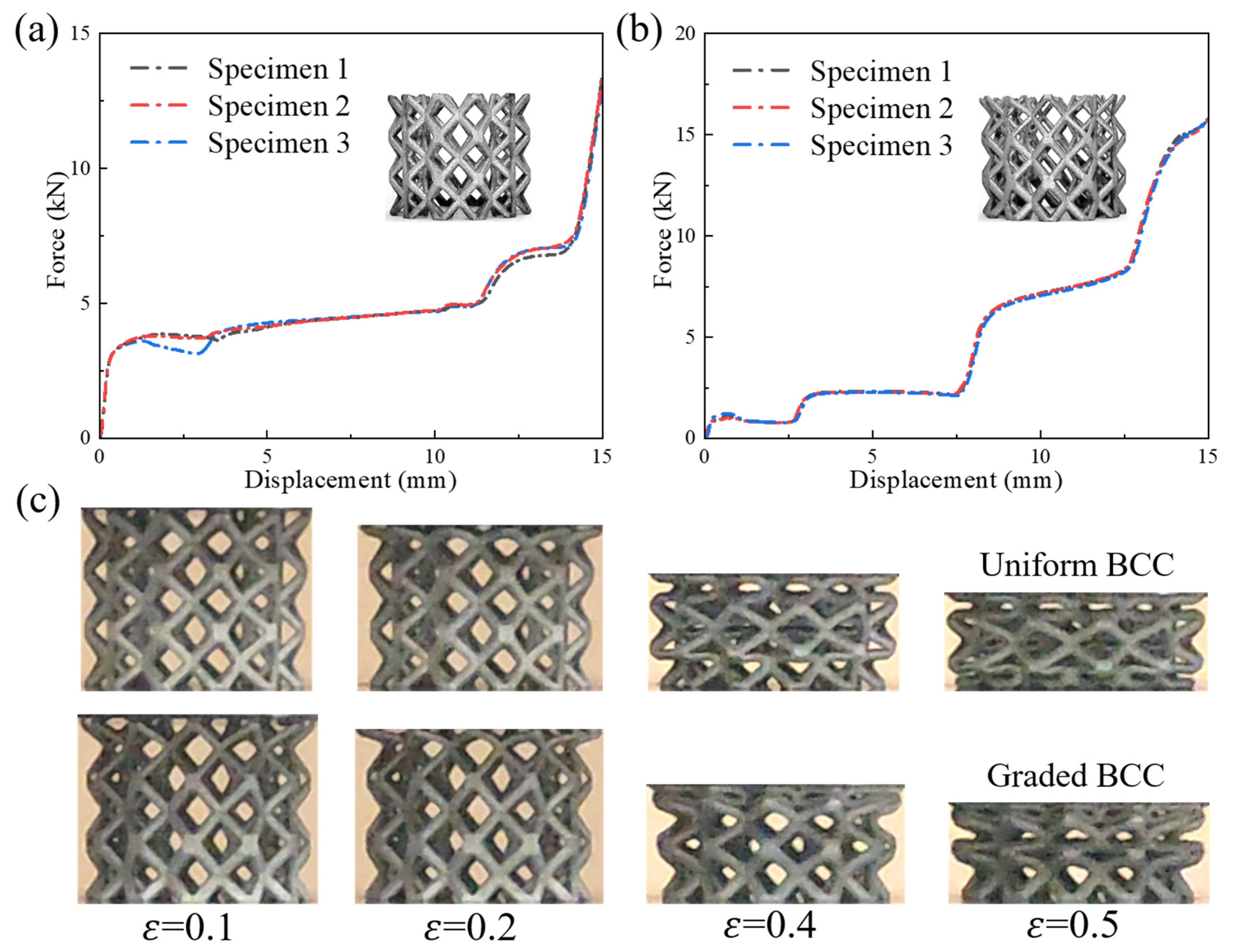
Figure 6a,b plot the experimental quasi-static compression force–displacement curves of the uniform and graded BCC LCS specimens, respectively. In both figures, three repeated experiments are shown, and the curves show good consistency. All the curves exhibit the typical characteristics of cellular materials under quasi-static compression: (i) the elastic deformation stage, (ii) the plastic yielding stage, (iii) the plateau stress stage, and (iv) the final densification stage. However, due to the effects of the gradient, the curve of the platform stress stage of the graded BCC LCS specimen was different from that of the uniform one. For the uniform BCC LCS specimen, a nearly constant plateau stress is observed in Figure 6a, while three obvious plateau stress stages are shown in Figure 6b. This phenomenon is closely related to the deformation processes shown in Figure 6c.
When compression strain was 0.1 or 0.2, uniform deformation could be observed in the original BCC LCS pattern. As the compression proceeded until a strain of 0.4, apparent localized deformation was seen in the intermediate regions of the original pattern. As the specimen was further compressed, the localized deformation propagated to both ends until densification. As for the graded pattern, different deformation processes could be witnessed, presenting a layer-by-layer deformation characteristic as a whole. When the compression strain was 0.2, the first upper layer deformed. When the structural pattern was compressed until a strain of 0.4, the first upper layer was completely compressed, and the intermediate layer started to deform. When the compression strain was 0.5, deformation further propagated, and the third bottom layer also started to deform. These deformation characteristics are consistent with the experimental curves in Figure 6b.

3.1.2. Validation of Simulation Results

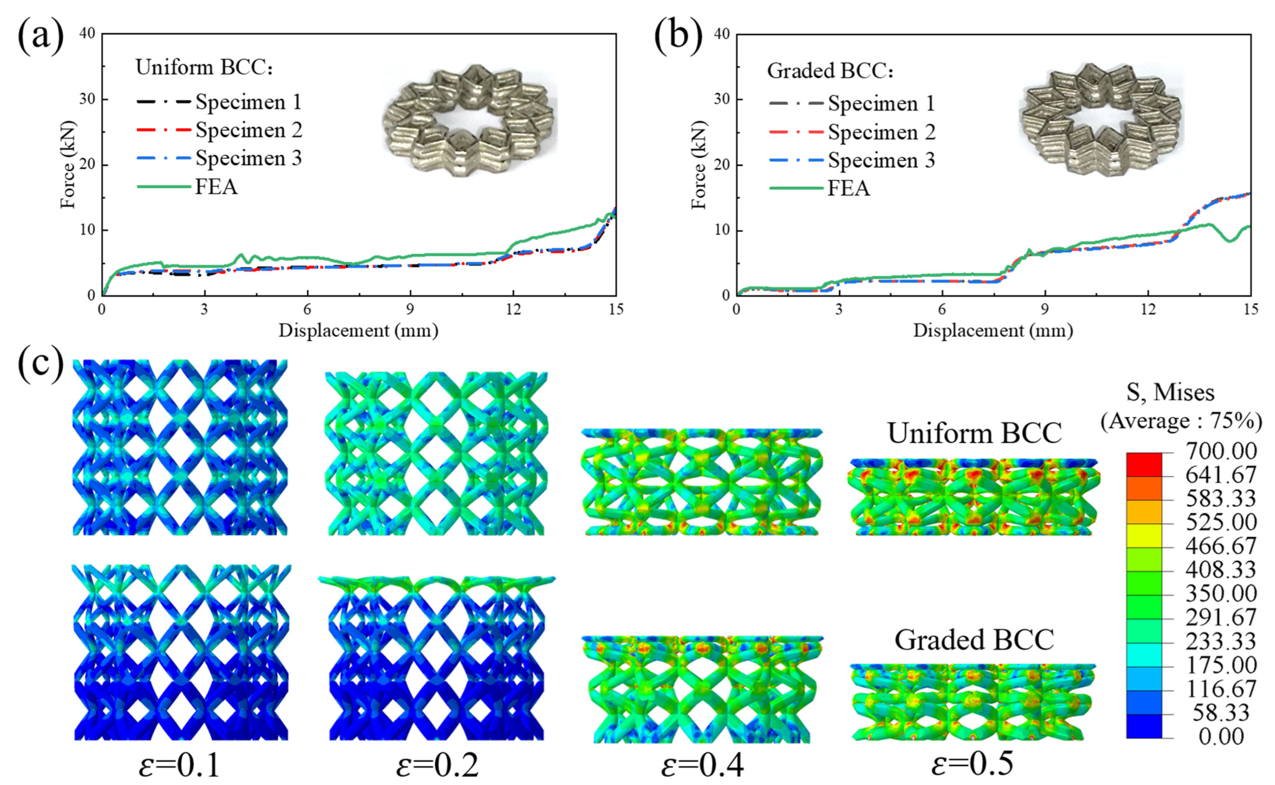
In this section, the quasi-static compression force–displacement results obtained from numerical simulation are compared with the experimental results in Figure 7. Herein, the simulated and experimental performance curves of the uniform and graded BCC LCS specimens are both compared. In addition, for a more intuitive comparison with the experimental deformation processes, simulated deformation processes of the BCC LCS specimens are also plotted in Figure 7c. It was observed that, for both the uniform and graded BCC LCS specimens, the simulated force–displacement curves as well as the deformation features were all consistent with the experimental results. In the following sections, a parametric analysis is described, as conducted through finite element analysis, and the detailed results are discussed below.

3.1.3. Effect of Relative Density

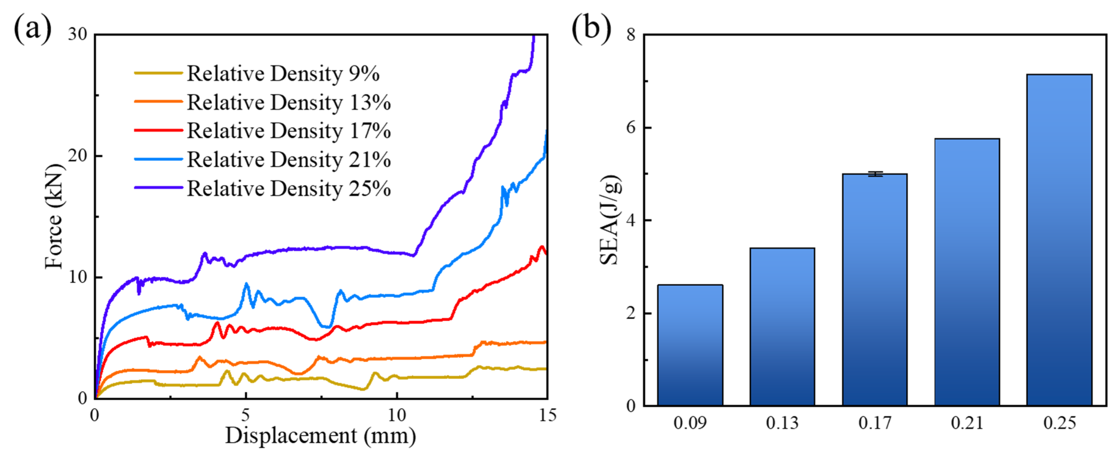
Effective relative density is one of the most important structural characteristics of cellular materials. It is important for cellular materials to reveal the relationships between relative density and specific energy absorption (SEA) characteristics. Simulated quasi-static compression force–displacement curves of the uniform BCC LCS specimens under five different relative densities (i.e., 9%, 13%, 17%, 21%, and 25%) are summarized in Figure 8a. Different relative densities were achieved by adjusting the diameters of the struts, and the relevant dimensions are listed in Table 1. The curve characteristics were almost the same under different effective relative densities, where elastic deformation stage, plastic yielding stage, plateau stress stage, and densification stage could be observed. The curves exhibited typical behavioral characteristics of cellular materials. As the effective relative density increased, the elastic modulus and the platform stress rose. However, the densification strain decreased as the relative density increased. Quasi-static SEA values of all the uniform configurations are illustrated in Figure 8b. The SEA values were 2.60 J/g, 3.39 J/g, 5.00 J/g, 5.76 J/g, and 7.15 J/g for the 9%, 13%, 17%, 21%, and 25% relative densities, respectively. The SEA almost showed a linear growth trend. When relative density increased from 9% to 25%, a 175% increase in SEA could be realized.

3.1.4. Effect of Gradient Distribution

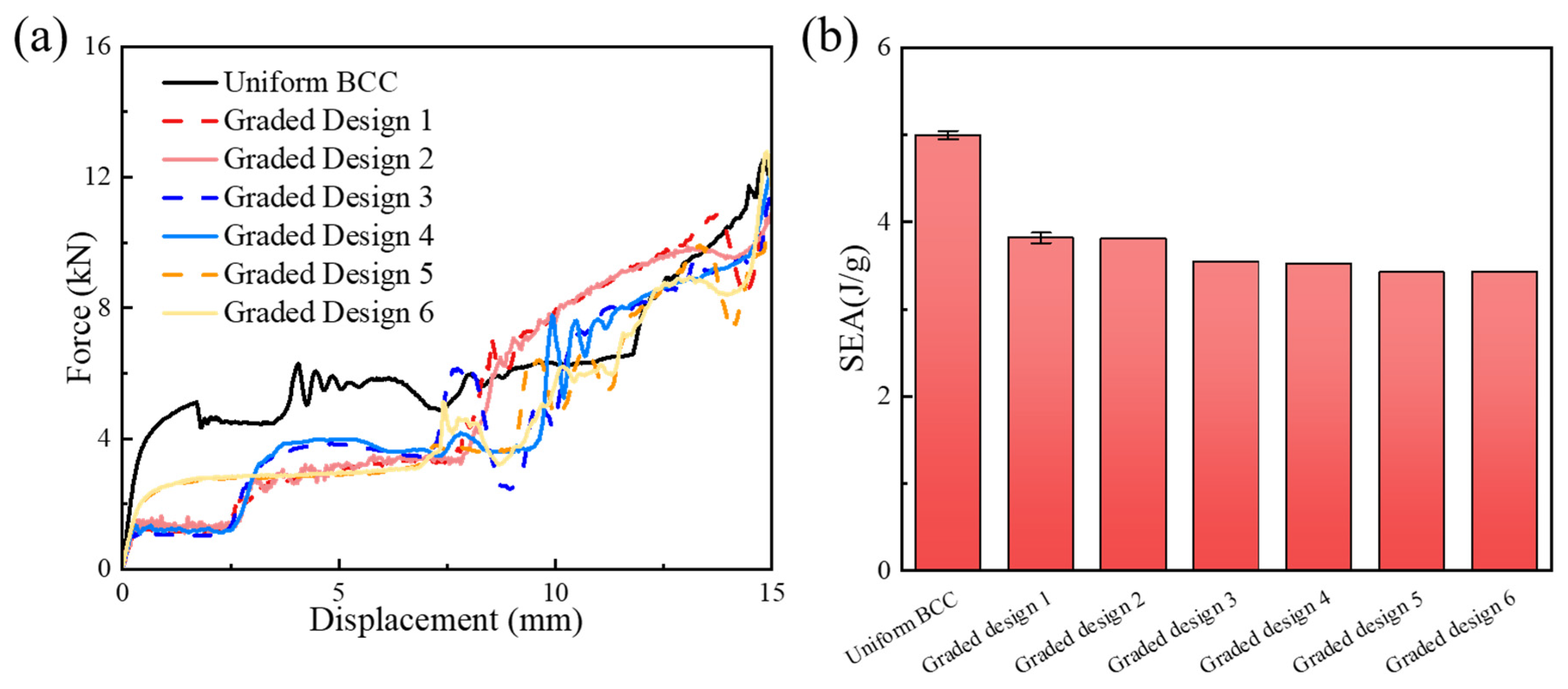
In order to further explore the influence of gradient distribution on the overall mechanical properties of the structure, quasi-static compression force–displacement curves of the as-designed six different gradient configurations are given in Figure 9a. It could be seen that different graded structural patterns exhibited similar mechanical performance. Three obvious plateau stress stages could be observed. The curves exhibited typical behavioral characteristics of graded cellular materials. In addition, graded design configurations (i.e., 1 and 2, or 3 and 4, or 5 and 6) almost exhibited the same mechanical performance. The reason was that, for example, the difference between the graded-1 and graded-2 configurations was only the loading direction. There was no strain rate effect or localized effect in quasi-static loading conditions, and thus, the mechanical properties of the graded-1 and graded-2 configurations were the same. In this section, only the quasi-static loading condition was considered. Thus, the same performance property was used. SEA values of all the graded configurations are summarized in Figure 9b. The quasi-static compression SEA values were 5.00 J/g, 3.82 J/g, 3.82 J/g, 3.54 J/g, 3.54 J/g, 3.42 J/g, and 3.42 J/g for the uniform, graded-1, graded-2, graded-3, graded-4, graded-5, and graded-6 configurations, respectively. The SEA values of the graded-1 and graded-2 configurations were the same. The same pattern was also observed among other configurations. Similar SEA values could be found in the graded configurations, which were consistent with the characteristics of performance curve patterns.

3.1.5. Deformation Mode

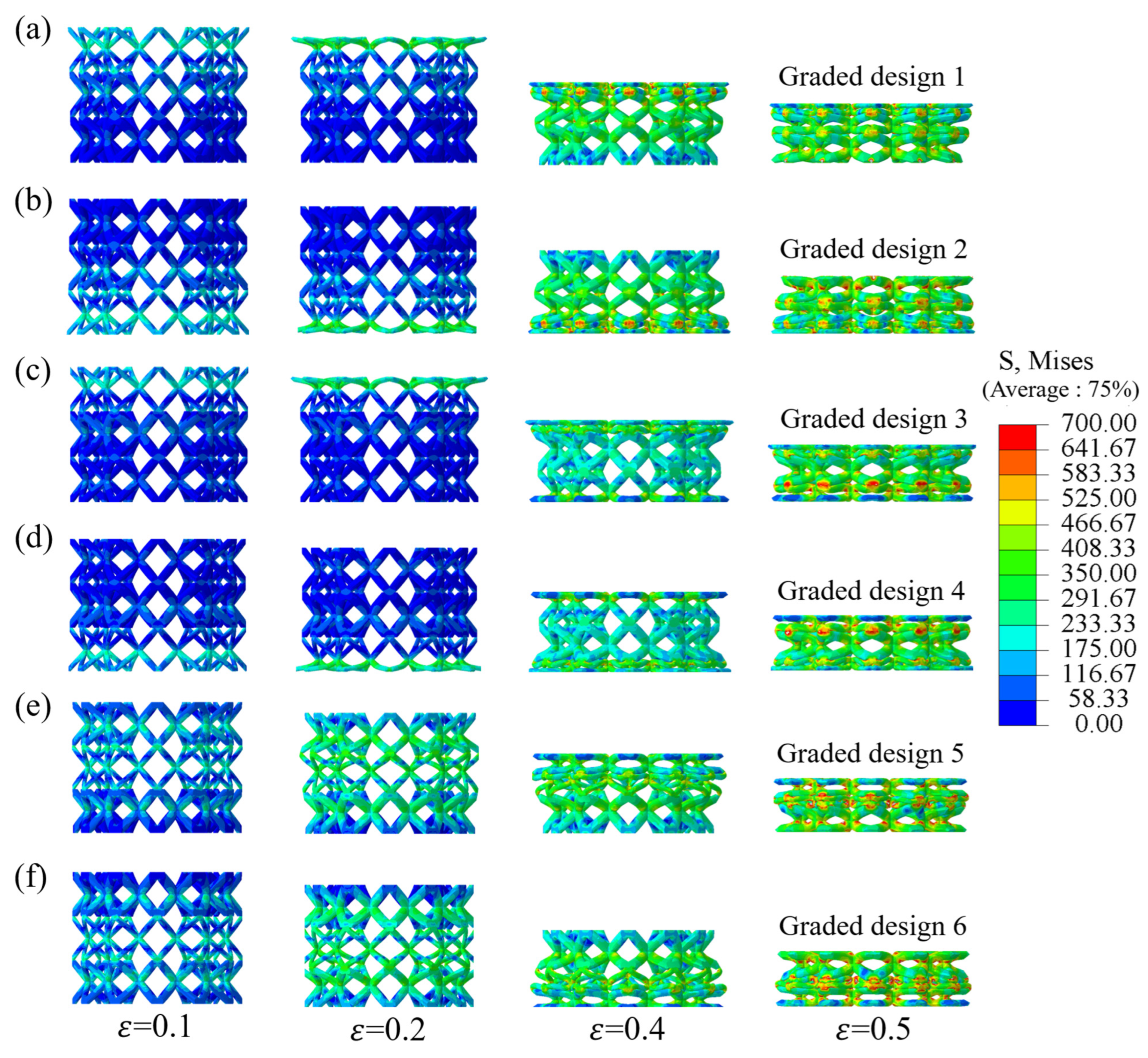
Quasi-static compression deformation processes of all the graded BCC LCS specimens are plotted in Figure 10. Herein, the deformation states at strains of 0.1, 0.2, 0.4, and 0.5 are all listed. Under quasi-static loading conditions, the deformation processes were closely related to the relative density distribution characteristics in different layers (0.17 relative density for the whole structure). The graded-1 BCC LCS specimen exhibited a typical deformation behavior of layer collapse from top to bottom. This was because the relative density of the top layer was the lowest, and the relative density of the bottom layer was the highest. As for the graded-2 specimen, due to the symmetry of the density distribution with the graded-1 configuration, the specimen exhibited a layer-by-layer collapse process from bottom to top. When the compression strain was 0.2, the first upper layer of the graded-3 specimen deformed. As the structure was compressed further, evident deformation was observed in the third bottom layer and finally propagated to the intermediate layer. Similarly, a predictable deformation process could also be observed in the graded-4 pattern, owing to the symmetry of the density distribution. As for the graded-5 specimen, the intermediate layer deformed first, and the top and bottom layers subsequently deformed in sequence. For the graded-6 specimen, the intermediate layer deformed first, and the bottom and top layers subsequently deformed in sequence. However, it should be noted that the localized deformations in the graded-5 and graded-6 specimens were not so obvious when compared with those of other structures. This was due to the boundary constraint effect. The intermediate layer density of graded-5 and graded-6 specimens was the lowest. Thus, the top and bottom layers would have strong constraints on them, limiting the localized deformation. To sum up, relative density distribution characteristics in different layers would significantly affect the quasi-static compression deformation processes. Specific deformation processes could be customized by adjusting the relative density distribution characteristics.

3.2. Dynamic Compression Mechanical Behavior

3.2.1. Low-Speed Compression Behavior (100/s)

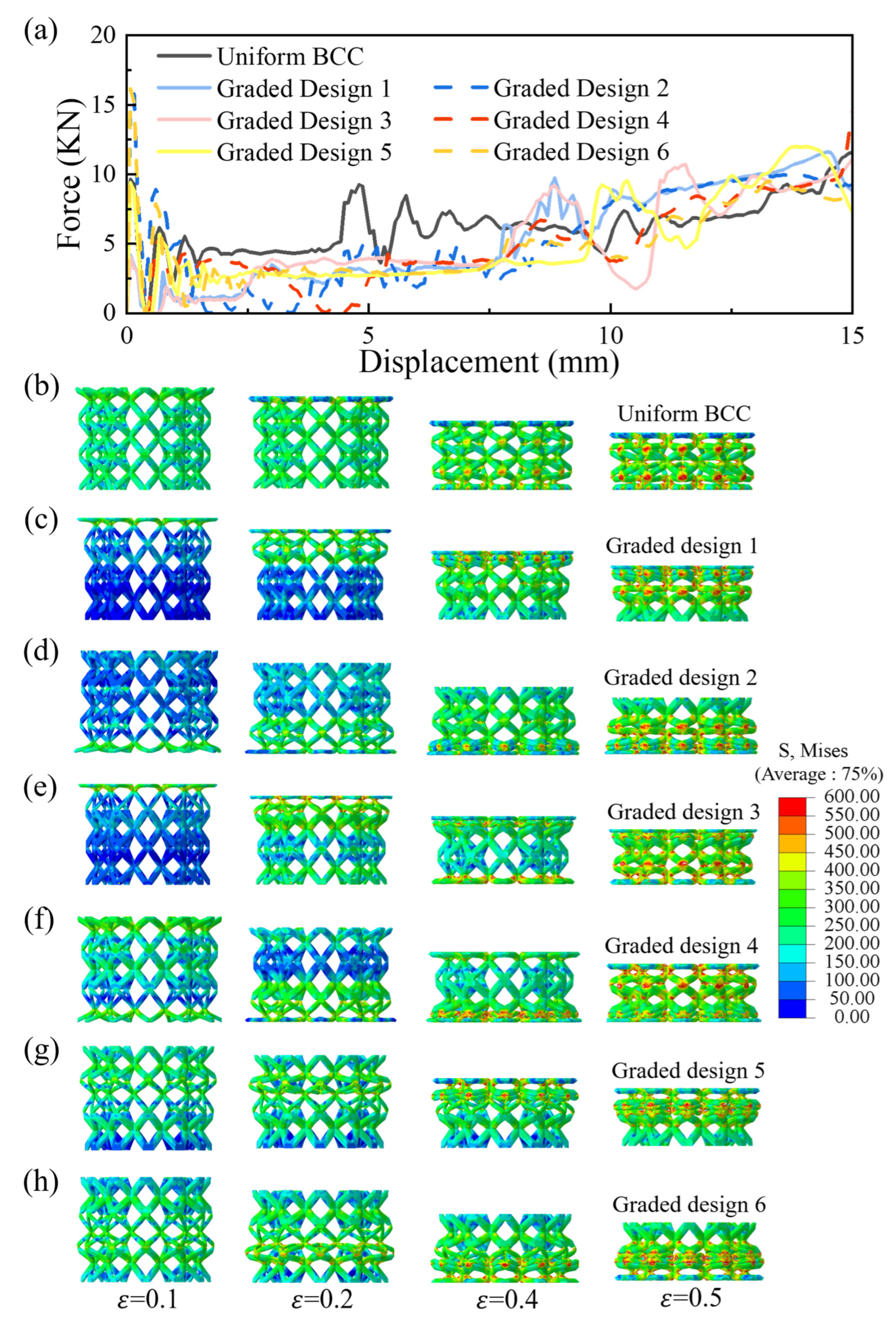
Herein, low-speed compression force–displacement curves and deformation processes of the uniform and graded BCC LCS specimens are illustrated in Figure 11a and Figure 11b–h, respectively. The differences in the low-speed compression force–displacement curves were small when compared with those under the quasi-static loading condition. In addition, the initial peak stress was not evident in the structural patterns. Graded structures still exhibited typical performance characteristics, where three obvious plateau stress stages were observed. As for the deformation process, under low-speed loading conditions, the top layer of the uniform BCC LCS specimen deformed first at a strain of 0.2. When the compression strain was 0.4, the bottom layer also deformed. Finally, evident localized deformation was observed in the intermediate layer at a strain of 0.5. For the graded-1 and graded-2 structures, they exhibited deformation characteristics from top to bottom and from bottom to top, respectively. As for the graded-3 structure, deformation propagated from the top layer to the bottom layer and finally to the intermediate layer. For the graded-4 structure, deformation propagated from the bottom layer to the top layer and finally to the intermediate layer. As for the graded-5 pattern, due to the greater effect of gradient distribution than low-speed impact effects, the specimen first deformed in the intermediate layer. Afterwards, the top and bottom layers deformed consecutively. For the graded-6 specimen, deformation propagated from the intermediate layer to the bottom layer and finally to the top layer. Deformation processes were closely related to the performance curves of the BCC LCS specimens. However, it should be noted that the mechanical behavior of the structural patterns under low-speed compression was not significantly different from that under quasi-static loading conditions.

3.2.2. Medium-Speed Compression Behavior (500/s)

Figure 12 plots the medium-speed compression force–displacement curves and deformation processes of the uniform and graded BCC LCS specimens. Initial peak stress, plateau stress, and densification can all be observed in Figure 12a. When compared with the quasi-static compression curves, the performance curves under low-speed loading showed a slight increase overall. In addition, the oscillation of the curves was also more pronounced. Deformation features were similar to those observed under the quasi-static or low-speed loading conditions. The top layer of the uniform BCC LCS specimen deformed first, and then the bottom layer also deformed. Finally, localized deformation propagated to the intermediate layer, and the densification stage began. The graded-1 structure showed a deformation mode of layer collapse from top to bottom, while the graded-2 structure presented a failure mode from bottom to top. As for the other structural patterns, the deformation processes were also similar to those under the low-speed loading conditions.

3.2.3. High-Speed Compression Behavior (1000/s)

Figure 13a and Figure 13b–h illustrate the high-speed compression force–displacement curves and deformation processes of the uniform and graded BCC LCS specimens, respectively. An apparent initial peak stress could be observed. The oscillation of the curves was also more pronounced when compared with that under the quasi-static, low-speed, or medium-speed loading conditions. A slight increase in the performance curves could also be realized. Figure 13b shows the high-speed compression deformation features of the uniform BCC LCS specimen. When the compression strain was 0.2, the top layer deformed. As the specimen was compressed further, the bottom layer also deformed. When the compression strain was 0.5, the whole structure entered the densification stage. High-speed compression deformation features of other graded structural patterns are plotted in Figure 13c–h. Differences could be observed when compared with other loading conditions. There existed a complicated competitive relationship between the deformation law induced by the gradient distribution and the localized deformation induced by high-speed loading. As for the gradient issue, deformation tended to follow the same gradient distribution. As for the high-speed loading, deformation tended to exhibit the characteristic of layer-by-layer collapse from top to bottom.

3.2.4. Key Property Parameter

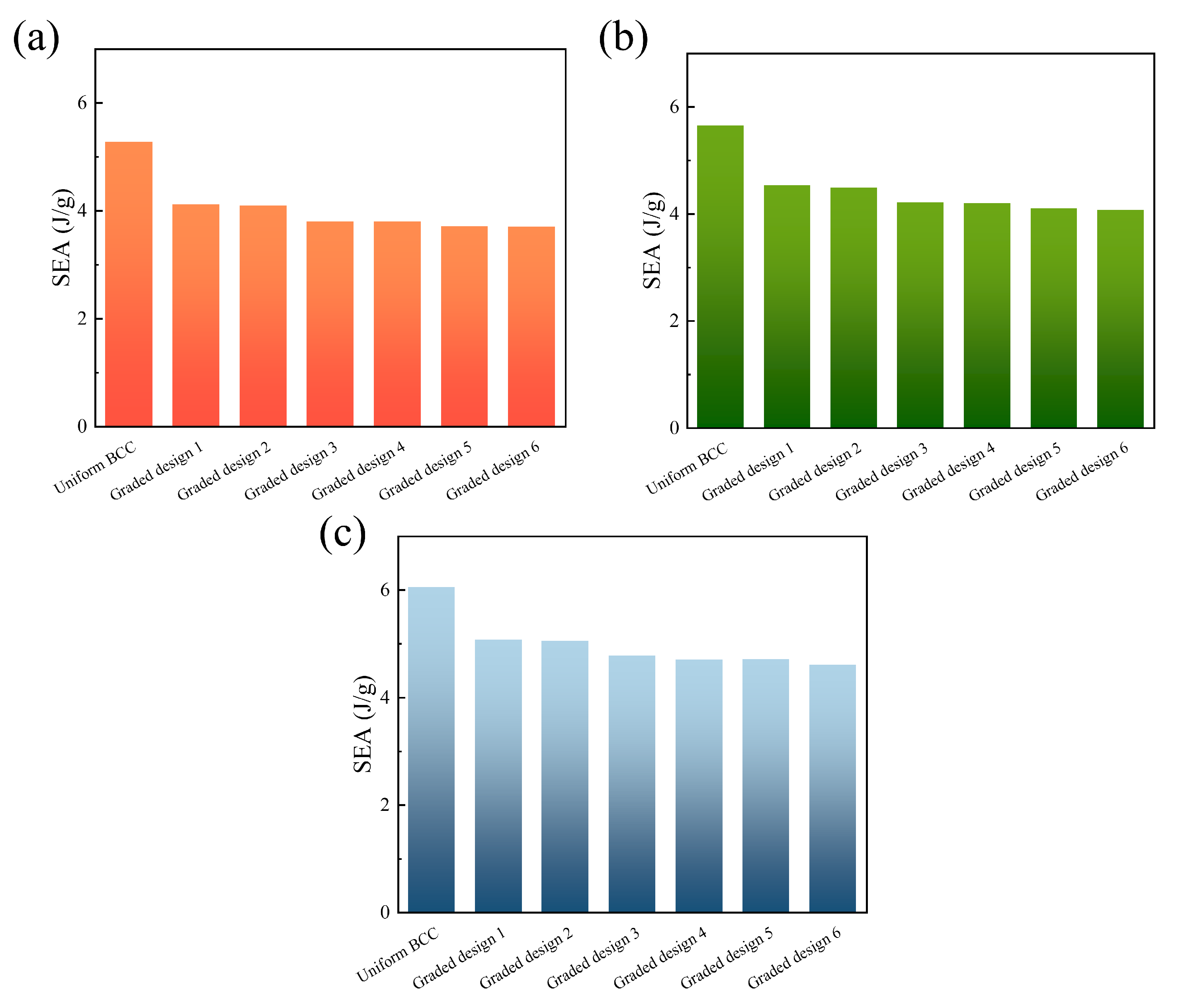
To quantitatively characterize the energy absorption characteristics of all the target structures under different loading conditions, the specific energy absorption (SEA) of all the BCC LCS specimens is plotted in Figure 14. Herein, the specific values under low-speed loading, medium-speed loading, and high-speed loading are all listed. Under low-speed loading conditions, SEA of the uniform, graded-1, graded-2, graded-3, graded-4, graded-5, and graded-6 specimens was 5.28 J/g, 4.12 J/g, 4.10 J/g, 3.80 J/g, 3.80 J/g, 3.71 J/g, and 3.71 J/g, respectively. Under medium-speed loading conditions, SEA of the uniform, graded-1, graded-2, graded-3, graded-4, graded-5, and graded-6 specimens was 5.65 J/g, 4.54 J/g, 4.49 J/g, 4.22 J/g, 4.20 J/g, 4.11 J/g, and 4.08 J/g, respectively. Under high-speed loading condition, SEA of the uniform, graded-1, graded-2, graded-3, graded-4, graded-5, and graded-6 specimens was 6.06 J/g, 5.08 J/g, 5.05 J/g, 4.77 J/g, 4.70 J/g, 4.71 J/g, and 4.61 J/g, respectively. As shown in Figure 14, the uniform specimen exhibited higher SEA values than graded structures across all loading speeds. Among the gradient designs, graded-1 and graded-2 demonstrated the highest SEA values. Generally, a higher SEA value could be obtained under a higher loading velocity. When compared with the SEA value under low-speed loading conditions, a 26.95% maximum increase could be seen in the graded-5 specimen under high-speed loading.

4. Conclusions

Uniform and graded BCC lattice cylindrical shells were proposed and fabricated with 316L stainless steel material. Experimental testing and numerical simulations were both utilized to investigate the quasi-static and dynamic compression behavior of the target structures. Finite element results were compared with the experimental results. Parametric studies were conducted to study the effects of relative density, gradient distribution, and loading velocity on the mechanical properties and deformation features. The insights gained from this study can be summarized as follows.
(1)
Under quasi-static compression loading, when the relative density of the uniform specimen increased from 9% to 25%, a 175% increase in SEA could be witnessed. Three distinct stress plateau stages were observed in the graded specimens, and the quasi-static compression deformation process was closely related to the relative density distribution characteristics of the different layers.
(2)
Under dynamic compression loading, a higher performance curve could be seen at a higher loading velocity. There existed a complicated competitive relationship between the deformation law induced by the gradient distribution and the localized deformation induced by high-speed loading.
(3)
As for the SEA value, the uniform specimen exhibited higher values than the graded structures across all loading speeds. Among the gradient designs, graded-1 and graded-2 ones demonstrated the highest SEA values. Additionally, a higher SEA value could be obtained under a higher loading velocity. When compared with the SEA value under low-speed loading conditions, a 26.95% maximum increase could be seen in the graded-5 specimen under high-speed loading.
In summary, uniform BCC LCS specimens exhibited optimal mechanical properties, while gradient structural patterns enabled controllable deformation features by regulating the spatial arrangement of the density layers. Future research will focus on establishing quantitative relationships between gradient distributions and failure modes, developing new hybrid design methods, and combining machine learning to optimize configurations, thereby advancing the application of functionally graded lattice structures in impact resistance and personalized customization fields. In addition, it is worth noting that additive manufacturing process parameters significantly affect the microstructure and mechanical properties of the lattice structure, which provides a new way for the precise regulation of the gradient structure. For example, the performance enhancement can be achieved by optimizing the printing strategy, which provides a new design for the aerospace field of the lightweight protective structure and the biomedical field of personalized implants and other application possibilities.

Author Contributions

Conceptualization, Y.G., M.C., W.L., W.C., Y.Q. and X.C.; methodology, Y.G., W.M. and W.C.; software, M.C., H.X., W.C. and S.W.; validation, Y.G., H.X., W.L., Y.Q., X.Z. and X.C.; investigation, Y.G., W.M., M.C. and S.W.; writing—original draft preparation, W.M., H.X. and S.W.; writing—review and editing, H.X., W.L., S.W. and X.Z.; visualization, W.M., M.C., W.L., Y.Q., X.Z. and X.C.; supervision, W.C., Y.Q., X.Z. and X.C. All authors have read and agreed to the published version of the manuscript.

Funding

The authors would like to thank the support from the National Natural Science Foundation of China (No. 12302482), the support from National Training Program of Innovation and Entrepreneurship for Undergraduates (No. 202510497085), the support from Wuhan Natural Science Foundation Exploration Program (Morning Light Program), and the support from General Program of Hubei Provincial Natural Science Foundation.

Data Availability Statement

The original contributions presented in the study are included in the article, further inquiries can be directed to the corresponding author.

Conflicts of Interest

The authors declare no conflicts of interest.

References

  1. Changdar, A.; Chakraborty, S.S.; Li, Y.; Wen, C. Laser additive manufacturing of aluminum-based stochastic and nonstochastic cellular materials. J. Mater. Sci. Technol. 2024, 183, 89–119. [Google Scholar] [CrossRef]
  2. Al-Jamal, A.A.; Barsoum, I.; Abu Al-Rub, R.K. Defect-sensitivity of stochastic and periodic minimal surface titanium cellular materials. Int. J. Mech. Sci. 2025, 289, 110063. [Google Scholar] [CrossRef]
  3. Hong, Y.; Li, X.; Yan, Z.; Liu, Z.; Zhuang, Z. Designing spongy-bone-like cellular materials: Matched topology and anisotropy. Int. J. Mech. Sci. 2025, 285, 109788. [Google Scholar] [CrossRef]
  4. Ramirez-Chavez, I.E.; Varma, R.; Anderson, D.; Lazar, P.J.L.; Shinde, M.; Goode, Z.; Bhate, D. Strain redistribution in stochastically perturbed single and dual-phase cellular materials under quasistatic compression. Manuf. Lett. 2024, 41, 1034–1045. [Google Scholar] [CrossRef]
  5. Cao, X.; Jiang, Y.; Zhao, T.; Wang, P.; Wang, Y.; Chen, Z.; Li, Y.; Xiao, D.; Fang, D. Compression experiment and numerical evaluation on mechanical responses of the lattice structures with stochastic geometric defects originated from additive-manufacturing. Compos. B Part Eng. 2020, 194, 108030. [Google Scholar] [CrossRef]
  6. Ha, N.S.; Lu, G. A review of recent research on bio-inspired structures and materials for energy absorption applications. Compos. Part B Eng. 2020, 181, 107496. [Google Scholar] [CrossRef]
  7. Bieler, S.; Weinberg, K. Energy absorption in lattice-structured materials under impact loading. Eur. J. Mech. A Solids 2025, 114, 105734. [Google Scholar] [CrossRef]
  8. Cao, X.; Duan, S.; Liang, J.; Wen, W.; Fang, D. Mechanical properties of an improved 3D-printed rhombic dodecahedron stainless steel lattice structure of variable cross section. Int. J. Mech. Sci. 2018, 145, 53–63. [Google Scholar] [CrossRef]
  9. Dong, Y.; Yan, F.; Zhang, Z. Three-dimensional annular negative stiffness honeycomb structure design and performance study. Compos. Struct. 2025, 367, 119229. [Google Scholar] [CrossRef]
  10. Zhang, Q.; Sun, Y. Energy absorption characteristic of auxetic metamaterials honeycombs and lattices with negative thermal expansion. Thin-Walled Struct. 2025, 208, 112824. [Google Scholar] [CrossRef]
  11. Cao, X.; Zhang, D.; Liao, B.; Fang, S.; Liu, L.; Gao, R.; Li, Y. Numerical analysis of the mechanical behavior and energy absorption of a novel P-lattice. Thin-Walled Struct. 2020, 157, 107147. [Google Scholar] [CrossRef]
  12. Viswanath, A.; Khalil, M.; Khan, M.K.A.; Cantwell, W.J.; Khan, K.A. Hierarchical cubic lattice structures with bending- and stretching-dominated cellular designs for enhanced buckling resistance. Int. J. Lightweight Mater. Manuf. 2025, 8, 310–320. [Google Scholar] [CrossRef]
  13. Huang, Z.; Cao, X.; Niu, H.; Ma, B.; Du, X.; Zhou, Z.; Yang, H.; Du, M.K. Numerical and experimental evaluations on the defect sensitivity of the performance of BCC truss-lattice structures. Mech. Mater. 2024, 191, 104937. [Google Scholar] [CrossRef]
  14. Rahimi, S.; Asghari, M. Design and evaluation of two proposed hybrid FCC-BCC lattice structures for enhanced mechanical performance. Heliyon 2025, 11, e40911. [Google Scholar] [CrossRef]
  15. Liang, Z.; Chen, X.; Sun, Z.; Guo, Y.; Li, Y.; Chang, H.; Zhou, L. A study on the compressive mechanical properties of 316L diamond lattice structures manufactured by laser powder bed fusion based on actual relative density. J. Manuf. Process. 2022, 84, 414–423. [Google Scholar] [CrossRef]
  16. Chen, Z.; Mordehai, D. Homogenization of the yield surface of body-centered cubic and octet lattice structures under multiaxial loadings. Int. J. Solids Struct. 2025, 320, 113486. [Google Scholar] [CrossRef]
  17. Lei, H.; Li, C.; Meng, J.; Zhou, H.; Liu, Y.; Zhang, X.; Wang, P.; Fang, D. Evaluation of compressive properties of SLM-fabricated multi-layer lattice structures by experimental test and μ-CT-based finite element analysis. Mater. Des. 2019, 169, 107685. [Google Scholar] [CrossRef]
  18. Zhang, P.; Yu, P.; Zhang, R.; Chen, X.; Tan, H. Grid octet truss lattice materials for energy absorption. Int. J. Mech. Sci. 2023, 259, 108616. [Google Scholar] [CrossRef]
  19. Deshpande, V.S.; Ashby, M.F.; Fleck, N.A. Foam topology: Bending versus stretching dominated architectures. Acta Mater. 2001, 49, 1035–1040. [Google Scholar] [CrossRef]
  20. Latture, R.M.; Rodriguez, R.X.; Holmes, L.R.; Zok, F.W. Effects of nodal fillets and external boundaries on compressive response of an octet truss. Acta Mater. 2018, 149, 78–87. [Google Scholar] [CrossRef]
  21. Deshpande, V.S.; Fleck, N.A. Collapse of truss core sandwich beams in 3-point bending. Int. J. Solids Struct. 2001, 38, 6275–6305. [Google Scholar] [CrossRef]
  22. Maiti, S.K.; Gibson, L.J.; Ashby, M.F. Deformation and energy absorption diagrams for cellular solids. Acta Metall. 1984, 32, 1963–1975. [Google Scholar] [CrossRef]
  23. Wang, Z.; Jiang, X.; Yang, G.; Song, B.; Sha, H. Design and mechanical performance analysis of T-BCC lattice structures. J. Mater. Res. Technol. 2024, 32, 1538–1551. [Google Scholar] [CrossRef]
  24. Zhao, L.; Zhang, J.; Yang, J.; Hou, J.; Li, J.; Lin, J. Microstructure and mechanical properties of 316L stainless steel manufactured by multi-laser selective laser melting (SLM). Mater. Sci. Eng. A 2024, 913, 147053. [Google Scholar] [CrossRef]
  25. Siddiqui, N.A.; Muzamil, M.; Jamil, T.; Hussain, G. Heat sources in wire arc additive manufacturing and their impact on macro-microstructural characteristics and mechanical properties—An overview. Smart Mater. Manuf. 2025, 3, 100059. [Google Scholar] [CrossRef]
  26. Strano, G.; Hao, L.; Everson, R.M.; Evans, K.E. Surface roughness analysis, modelling and prediction in selective laser melting. J. Mater. Process. Technol. 2013, 213, 589–597. [Google Scholar] [CrossRef]
  27. Zhong, T.; He, K.; Li, H.; Yang, L. Mechanical properties of lightweight 316L stainless steel lattice structures fabricated by selective laser melting. Mater. Des. 2019, 181, 108076. [Google Scholar] [CrossRef]
  28. McKown, S.; Shen, Y.; Brookes, W.K.; Sutcliffe, C.J.; Cantwell, W.J.; Langdon, G.S.; Nurick, G.N.; Theobald, M.D. The quasi-static and blast loading response of lattice structures. Int. J. Impact Eng. 2008, 35, 795–810. [Google Scholar] [CrossRef]
  29. Guo, H.; Takezawa, A.; Honda, M.; Kawamura, C.; Kitamura, M. Finite element simulation of the compressive response of additively manufactured lattice structures with large diameters. Comput. Mater. Sci. 2020, 175, 109610. [Google Scholar] [CrossRef]
  30. Ptochos, E. Elastic modulus and Poisson’s ratio determination of micro-lattice cellular structures by analytical, numerical and homogenisation methods. J. Sandw. Struct. Mater. 2012, 14, 597–626. [Google Scholar] [CrossRef]
  31. Ushijima, K.; Cantwell, W.; Mines, R.; Tsopanos, S.; Smith, M. An investigation into the compressive properties of stainless steel micro-lattice structures. J. Sandw. Struct. Mater. 2010, 13, 303–329. [Google Scholar] [CrossRef]
  32. Babaee, S.; Jahromi, B.H.; Ajdari, A.; Nayeb-Hashemi, H.; Vaziri, A. Mechanical properties of open-cell rhombic dodecahedron cellular structures. Acta Mater. 2012, 60, 2873–2885. [Google Scholar] [CrossRef]
  33. Cao, X.; Ren, X.; Zhao, T.; Li, Y.; Xiao, D.; Fang, D. Numerical and theoretical analysis of the dynamic mechanical behaviour of a modified rhombic dodecahedron lattice structure. Int. J. Mech. Mater. Des. 2021, 17, 271–283. [Google Scholar] [CrossRef]
  34. Scalzo, F.; Totis, G.; Vaglio, E.; Sortino, M. Experimental study on the high-damping properties of metallic lattice structures obtained from SLM. Precis. Eng. 2021, 71, 63–77. [Google Scholar] [CrossRef]
  35. Zhang, H.; Hu, D.; Peng, H.; Yuan, W.; Zhang, Z.; Yang, Z.; Zhang, Z. In-plane crashworthiness study of bio-inspired metallic lattice structure based on deep-sea glass sponge. Thin-Walled Struct. 2024, 205, 112505. [Google Scholar] [CrossRef]
  36. Collini, F.; Meneghetti, G. Towards a fracture mechanics-based fatigue assessment of lattice structures obtained from additive manufacturing of metallic powders. Mater. Des. 2024, 244, 113077. [Google Scholar] [CrossRef]
  37. Waqar, S.; Hussain, S.; Ren, C.; Wang, M.; Nazir, A.; Dan, X.; Wang, C.; Chen, Z. Superior strength and energy absorption capability of LPBF metallic functionally graded lattice structures. Thin-Walled Struct. 2024, 205, 112471. [Google Scholar] [CrossRef]
  38. Eren, O.; Yüksel, N.; Börklü, H.R.; Sezer, H.K.; Canyurt, O.E. Deep learning-enabled design for tailored mechanical properties of SLM-manufactured metallic lattice structures. Eng. Appl. Artif. Intell. 2024, 130, 107685. [Google Scholar] [CrossRef]
  39. Arslan Bin Riaz, M.; Güden, M. A review of the experimental and numerical studies on the compression behavior of the additively produced metallic lattice structures at high and low strain rates. Def. Technol. 2025, 49, 1–49. [Google Scholar] [CrossRef]
  40. Wu, F.; Lin, C.; Ge, S.; Xue, X. Energy absorption performance of woven metallic lattices with orthogonal spiral wires under quasi-static compression. Thin-Walled Struct. 2024, 202, 112121. [Google Scholar] [CrossRef]
  41. Zeng, R.; Xu, M.; Wang, Y.; Guo, J.; Zhang, R.; Yan, B.; Zhao, Z.; Wang, P.; Duan, S.; Lei, H. Three-dimensional bi-metallic lattice with multi-directional zero thermal expansion. Compos. Struct. 2023, 323, 117499. [Google Scholar] [CrossRef]
  42. Song, W.; Feng, G.; Yu, G.; Shi, G.; Xiao, L. Dynamic mechanical behavior of additively manufactured bio-inspired metallic lattice structure subjected to high strain rate impact loading. Int. J. Impact Eng. 2023, 181, 104752. [Google Scholar] [CrossRef]
  43. Mazur, M.; Leary, M.; McMillan, M.; Sun, S.; Shidid, D.; Brandt, M. Mechanical properties of Ti6Al4V and AlSi12Mg lattice structures manufactured by Selective Laser Melting (SLM). In Laser Additive Manufacturing: Materials, Design, Technologies, and Applications; Taylor & Francis Inc.: Philadelphia, PA, USA, 2017; pp. 119–161. [Google Scholar]
  44. Song, X.; Zeng, C.; Hu, J.; Zhao, W.; Liu, L.; Liu, Y.; Leng, J. Compressive behavior and energy absorption of novel body-centered cubic lattice metamaterials incorporating simple cubic truss units. Compos. Struct. 2025, 367, 119230. [Google Scholar] [CrossRef]
  45. Wang, Y.; Ren, X.; Chen, Z.; Jiang, Y.; Cao, X.; Fang, S.; Zhao, T.; Li, Y.; Fang, D. Numerical and experimental studies on compressive behavior of Gyroid lattice cylindrical shells. Mater. Des. 2020, 186, 108340. [Google Scholar] [CrossRef]
  46. Zhang, T.; Liu, F.; Chen, J.; Tang, Y.; Zhang, K.; Xie, H.; Xu, T. Dual-graded lattice with mechanical bionics to enhance fatigue performance. Int. J. Mech. Sci. 2024, 279, 109474. [Google Scholar] [CrossRef]
  47. Laskowska, D.; Szatkiewicz, T.; Bałasz, B.; Mitura, K. Mechanical Properties and Energy Absorption Abilities of Diamond TPMS Cylindrical Structures Fabricated by Selective Laser Melting with 316L Stainless Steel. Materials 2023, 16, 3196. [Google Scholar] [CrossRef]
  48. Shahriyari, E.; Khiavi, S.G.; Divandari, M.; Ali Boutorabi, S.M. Effect of unit cell topologies on mechanical properties of cylindrical lattice structures fabricated by indirect additive manufacturing. J. Mater. Res. Technol. 2025, 36, 2785–2798. [Google Scholar] [CrossRef]
  49. Xue, X.; Gao, J.; Zheng, C.; Li, Z.; Liao, J.; Zhang, M. Energy absorption and vibration characteristics of metal/polymer composited pyramidal lattice cylinder structure. Structures 2025, 76, 108878. [Google Scholar] [CrossRef]
  50. Zhao, W.; Liu, T.; Chen, L.; Guo, Y.; Pan, X.; Zhu, S.; Li, W. Influence of density gradient and hybrid effect on quasi-static axial crushing behavior of lattice cylindrical structures. Thin-Walled Struct. 2023, 186, 110720. [Google Scholar] [CrossRef]
  51. Kathiresan, M.; Rajamohan, V.; Immanuel R, J.; Gnanasekar, S. Crashworthiness of pomelo-inspired PLA structures with gradient cellular design. Int. J. Mech. Sci. 2025, 299, 110402. [Google Scholar] [CrossRef]
  52. Huang, J.; Zhou, H.; Huang, W.; Zhang, Y.; Du, G.; Lu, W.; Xiang, X.; Gou, J. Design and crashworthiness analysis of novel gradient hashtag-shaped fractal thin-walled structure. Mater. Des. 2025, 254, 114076. [Google Scholar] [CrossRef]
  53. Sun, Z.; Gong, Y.; Tian, Y.; Lang, J.; Zhang, J.; Zhao, L.; Hu, N. Design and Mechanical Properties of Layered Gradient Lattice Structures Based on Additive Manufacturing. Addit. Manuf. Front. 2025, 4, 200188. [Google Scholar] [CrossRef]
  54. Yin, S.; Guo, W.; Wang, H.; Huang, Y.; Yang, R.; Hu, Z.; Chen, D.; Xu, J.; Ritchie, O.R. Strong and Tough Bioinspired Additive-Manufactured Dual-Phase Mechanical Metamaterial Composites. J. Mech. Phys. Solids 2021, 149, 104341. [Google Scholar] [CrossRef]
  55. Wang, Z.; Liu, Z.; Tao, C.; Liang, X. Crashworthiness and optimization design of additive manufacturing double gradient lattice enhanced thin-walled tubes under dynamic impact loading. Eng. Fail. Anal. 2024, 166, 108865. [Google Scholar] [CrossRef]
  56. Lin, H.-B.; Liu, H.-T. Load carrying capacity analysis and gradient design of new 3D zero Poisson’s ratio structures. Mater. Today Commun. 2023, 36, 106915. [Google Scholar] [CrossRef]
  57. Wei, Z.; Wang, H.; Bi, Y.; Li, Y.; Li, B.; Wang, B. Crashworthiness and gradient optimization of multi-cell thin-walled structures inspired by leaf venation in royal water lily. In Mechanics of Advanced Materials and Structures; Taylor & Francis Inc.: Philadelphia, PA, USA, 2024; pp. 1–17. [Google Scholar]
Figure 1. Illustration of the (a) original and (b) graded BCC lattice cylindrical shells. The detailed geometric dimensions are also marked.
Metals 15 00895 g001
Figure 2. (a) Design dimensions of the dog-bone shaped specimen for tensile testing; 3D-printed (b) dog-bone tensile specimen and (c) uniform and graded BCC LCS specimens.
Metals 15 00895 g002
Figure 3. SEM images of the fabricated (a) uniform and (b) graded BCC LCS samples.
Metals 15 00895 g003
Figure 4. (a) Universal testing machine for quasi-static tensile and compression tests. (b) Uniaxial tensile of dog-bone specimens. (c) Tensile stress–strain curves of the dog-bone specimens.
Metals 15 00895 g004
Figure 5. (a) Finite element model of BCC LCS specimen. (b) Boundary conditions settings.
Metals 15 00895 g005
Figure 6. Experimental quasi-static compression force–displacement curves of the (a) uniform and (b) graded BCC LCS specimens. (c) Deformation processes of the BCC LCS specimens.
Metals 15 00895 g006
Figure 7. Comparison of the force–displacement curves of (a) uniform and (b) graded BCC LCS specimens under compression obtained from experimental testing and numerical simulations. (c) Simulated deformation processes of the BCC LCS specimens.
Metals 15 00895 g007
Figure 8. Quasi-static compression (a) force–displacement curves and (b) SEA of the uniform BCC LCS specimens with different relative densities.
Metals 15 00895 g008
Figure 9. Quasi-static compression (a) force–displacement curves and (b) SEA of the graded BCC LCS specimens with different relative densities.
Metals 15 00895 g009
Figure 10. Quasi-static compression deformation processes of six different graded BCC LCS specimens: (a) gradient design 1; (b) gradient design 2; (c) gradient design 3; (d) gradient design 4; (e) gradient design 5; (f) gradient design 6.
Metals 15 00895 g010
Figure 11. Low-speed compression (a) force–displacement curves and (bh) deformation processes of the uniform and graded BCC LCS specimens. Herein, low-speed compression deformation processes of all the BCC LCS specimens were plotted.
Metals 15 00895 g011
Figure 12. Medium-speed compression (a) force–displacement curves and (bh) deformation processes of the uniform and graded BCC LCS specimens. Herein, medium-speed compression deformation processes of all the BCC LCS specimens are plotted.
Metals 15 00895 g012
Figure 13. High-speed compression (a) force–displacement curves and (bh) deformation processes of the uniform and graded BCC LCS specimens. Herein, high-speed compression deformation processes of all the BCC LCS specimens are plotted.
Metals 15 00895 g013
Figure 14. SEA of all the BCC LCS specimens under dynamic compression conditions: (a) low-speed loading; (b) medium-speed loading; (c) high-speed loading.
Metals 15 00895 g014
Table 1. Geometric dimensions of the as-designed BCC LCS lattice structures.
Sample ρ ¯ Scaffold   Density   ( g / c m 3 ) L 1 (mm) L 2 (mm) H (mm) Strut   Diameter   D  (mm)
Layer 1Layer 2Layer 3
Uniform BCC0.090.7182030250.6860.6860.686
0.131.0370.8400.8400.840
0.171.3570.9740.9740.974
0.211.6761.0961.0961.096
0.251.9951.2121.2121.212
Graded BCCGraded-10.171.3572030250.6860.9741.212
Graded-21.2120.9740.686
Graded-30.6861.2120.974
Graded-40.9741.2120.686
Graded-50.9740.6861.212
Graded-61.2120.6860.974
Table 2. Comparison of as-designed and measured masses of the BCC LCS samples.
Sample ρ ¯ Scaffold   Density   ( g / c m 3 ) Designed Mass (g)Measured Mass (g)Average (g)Error
Uniform BCC0.171.35713.30912.409
12.887
12.714
12.6704.80%
Graded BCC13.23812.621
13.045
12.736
12.8013.30%
Table 3. Material properties of the 316L stainless steel material.
Density (g/cm3)Young’s Modulus (GPa)Poisson’s RatioInitial Yield Strength (MP)Ultimate Strength (MPa)Ultimate Strain
7.89380.32438000.43
Disclaimer/Publisher’s Note: The statements, opinions and data contained in all publications are solely those of the individual author(s) and contributor(s) and not of MDPI and/or the editor(s). MDPI and/or the editor(s) disclaim responsibility for any injury to people or property resulting from any ideas, methods, instructions or products referred to in the content.